1995年Ultrasonic Elliptical Vibration Cutting
超声波震动仪的作用原理

超声波震动仪的作用原理
超声波震动仪(Ultrasonic vibrator)是一种利用超声波技术产生震动的装置。
它的作用原理基于以下几个方面:
1. 压电效应:超声波震动仪通常采用压电陶瓷材料,例如压电陶瓷晶片。
这些陶瓷材料可以在电场的作用下发生压电效应,即在电场的激励下,会引起晶片的尺寸发生微小的变化,从而产生机械振动。
2. 谐振结构:超声波震动仪通常采用谐振结构,使得压电陶瓷晶片能够在特定的频率范围内发生共振。
当施加电场激励时,压电陶瓷晶片会以谐振频率振动,从而产生更强的机械振动效果。
3. 超声波传播:超声波震动仪在谐振状态下,会产生高频的机械振动,这些振动以超声波的形式传播。
超声波具有高频率和短波长的特点,能够传播到较远的距离,并且能够在介质中传递能量。
综合以上原理,超声波震动仪通过施加电场激励使压电陶瓷晶片共振,产生高频的机械振动,并将这种振动以超声波的形式传播出去。
超声波震动仪在实际应用中具有多种用途,例如清洁、切割、焊接、检测、测量等领域。
超声钻削研究综述
内燃机与配件———————————————————————作者简介:柏广才(1971-),男,江苏淮安人,大专,普斐特油气工程(江苏)股份有限公司副总经理,主要从事石油机械产品加工工艺和工程技术的研发。
0引言传统钻削过程受钻削空间的限制,导致排屑和冷却困难,是钻削轴向力较大,同时过大的轴向力在钻头钻穿工件时使工件变形增大,造成钻削过程的飞边和毛刺;而切屑在顺着排屑槽排出时会与已加工表面划擦,造成钻削温度较高和孔表面质量变差[1]。
同时普通钻削过程,特别是小孔钻削过程,钻头的刚度较差,若工件表面不平经常出现钻头偏置,导致孔的位置精度较低。
针对传统钻削中存在的上述问题,学者通过研究提出了超声辅助钻削技术,即在传统钻削的过程中施加一个高频的振动,辅助钻削过程。
超声振动的引入是原有的钻削运动过程中引入另一个运动,形成新的刀具运动轨迹和形成新的切削动力学过程,通过合理的匹配振动的频率和振幅,优化传统的钻削过程。
高频振动的引入使钻削过程中刀具不断的与工件接触和分离,使原来的连续钻削过程转变为断续切削过程,促使切屑断裂和冷却液进入,降低切削刃的温度,减小磨损;同时高频振动不断的摩擦孔壁,降低孔的表面粗糙度,提升孔的加工质量。
1超声钻削技术分类与特点超声辅助钻削技术按不同振动的来源、形式和作用位置的不同可以划分成不同的类别。
①超声辅助钻削中依据振动来源的不同可分为自激振动和受迫振动辅助钻削。
自激振动中的振动来源于系统自身,如机床收到敲击后引起的自身的振动,通过将振动传递到工件,迫使工件振动,自激振动受系统阻尼的影响无法持续,同时振动的频率受系统结构的限制,无法调节,致使整个振动过程无法控制,因此一般不在实际钻削过程中使用。
强迫振动通过外部的驱动电路和结构产生有规律的振动并将振动传递到工件或者钻头,实现振动辅助加工,强迫振动的频率和振幅均有电路控制,可调节性强,因此被广泛使用。
目前采用的超声辅助钻削技术多为强迫辅助钻削。
超洁净PTFE车削加工切削参数对表面形貌及粗糙度变化影响

Vol. 46 No. 5
May. 2022
第46卷第
5期
2022年5月
液压与毛动Chinese Hydraulics & Pneumatics
doi: 10.11832/j.
issn. 1000-485&
2022.05.003
超洁净PTFE车削加工切削参数对表面形貌及 粗糙度变化影响
颖惠民付嬪媛▽,刘 范▽,苏 芮1,阮晓东1
(1.浙江大学流体动力与机电系统国家重点实验室,浙江杭州
310027
;
2.浙江启尔机电技术有限公司,浙江杭州
311305)
摘要:聚四氟乙烯(PTEE)是超洁净流控元件的主要材料之一。针对聚四氟乙烯机械加工后的表面
粗糙度问题,从改变进给量及车刀材料选择和切削液是否使用的角度探究机械加工PTFE表面形貌的形成 机理,发现了随着车刀停留时间的增加,PTFE表面粗糙度迅速降低并最终保持在一个稳定值,而车刀材料和
是否使用切削液也对PTFE机械加工后的表面形貌有非常显著的影响;通过共聚焦激光显微镜和原子力显
微镜(AFM),在不同的尺度下观察了加工后PTFE的表面形貌,为从微观层面解释聚四氟乙烯机械加工后表 面形貌的形成提供了直观的观测结果,从而揭示了表面形貌与车削加工参数的映射关系,并为氟塑料车削工 艺的优化提供了指导性依据。关键词:PTFE
;
车削;表面形貌;粗糙度
中图分类号:TH137 文献标志码:B 文章编号:10004858 (2022) 05-0026-10
The Influence of Cutting
Parameters
on Surface
Morphology and
Roughness During the Ultra-Clean PTFE Turning Process
YING Hui-min1, FU Jing-yuan1'2, LIU Fan1'2, SU Rui1, RUAN Xiao-dong1
(1. State Key Laboratory of Fluid Power and Mechatronic Systems, Zhejiang University
USM(Ultrasonic Machining)超声加工
USM1.定义USM(Ultrasonic Machining)超声加工是利用超声振动工具在有磨料的液体介质中或干磨料中产生磨料的冲击、抛磨、液压冲击及由此产生的气蚀作用来去除材料,或给工具或工件沿一定方向施加超声频振动进行振动加工,或利用超声振动使工件相互结合的加工方法。
几十年来,超声加工技术发展迅速,在超声振动系统、深小孔加工、拉丝模及型腔模具研磨抛光、超声复合加工领域均有较广泛的研究和应用,尤其是在难加工材料领域解决了许多关键性的工艺问题,取得了良好的效果。
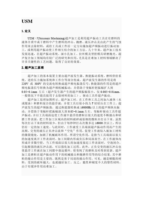
2.超声加工原理超声加工的基本装置主要由超声波发生器、换能振动系统、磨料供给系统、进给压力施加系统和工作台等部分组成。
超声波发生器的作用是将220V 或380V 的交流电转换成超声频电振荡信号;换能器的作用是将超声频电振荡信号转换为超声频机械振动;并借助于变幅杆把振幅扩大到0.05~0.1mm 左右(超声发生器产生的超声频振幅很小,仅0.005~0.01mm,一般情况下不能直接用于去除材料的加工),驱动工具作超声振动。
超声加工原理如图所示。
超声加工时,在工件和工具之间加入液体(水或煤油)和磨料混合的悬浮液,并使工具以很小的力F轻轻压在工件上。
超声波发生的超声频振荡,通过换能器转换成16000Hz以上的超声频纵向振动,并借助于变幅杆把振幅放大到0.05~0.1mm左右。
变幅杆驱动工具作超声振动,并以工具端面迫使工作液中悬浮的磨粒以很大的速度不断撞击和研磨工件表面,把工件加工区域内的材料破碎成很细的微粒并打击下来。
虽然每次打击下来的材料很少,但由于每秒钟打击次数多达16000次以上,所以仍有一定的加工速度。
与此同时,工作液受工具端面超声振动作用而产生的高频、交变的液压正负冲击波和“空化”作用,促使工作液钻入被加工材料的微裂缝处,加剧了机械破坏作用。
所谓空化作用,是指当工具端面以很大的加速度离开工件表面时,加工间隙内形成负压和局部真空,在工作液体内形成许多微空腔,当工件端面以很大的加速度接近工件表面时,空泡闭合,引起极强的液压冲击波,可以强化加工过程。
微电子封装超声键合机理与技术中的科学问题

须深入理解制造装备进行的工艺过程的原理 和细节。 超声键合是复杂物理、 力学作用下 的封装过程, 使金属材料在微米和毫秒时空 中形成界面键合。2003 年以来, 中南大学课 973 ” 题组, 在国家“ 计划项目的支持下, 进行 了超声键合机理的相关研究, 获得深入的理 解和工艺优化方向的认识。 本文回顾了封装 的发展, 介绍了科学问题的产生, 以及所使用 的键合动力学研究手段。
[5 ]
。
微电子封装已成为制造大规模集成电路的关键 之一。随着芯片特征线宽减小, 芯片不断变薄, 芯片 的前道制作与后道封装不断融合, 许多先进的封装 工艺与技术应运而生, 其中可望应对 32nm 特征线宽 芯片封装要求的新技 术 主 要 有: 晶 圆 级 封 装 ( wafer level Packaging , WLP ) 、 系 统 级 封 装 ( System in a
二、现代微电子制造业中的封装互连
1. 微电子封装和电气互连 微电子封装,是集成电路( IC ) 芯片转变为功能 产品的最后一个制造过程, 封装为芯片进入工作状 态提供信号与能量传输必须的电气连接, 同时提供 散热通道和可靠的物理支撑 / 保护。 使用中的集成 电路芯片必须与外界隔离, 以防止空气中的杂质对 芯片电路的腐蚀而造成电气性能下降 。 封装后的芯 片也便于安装和运输。 封装技术的好坏还直接影响 到芯片自 身 性 能 的 发 挥 和 与 之 连 接 的 印 制 电 路 板 ( PCB ) 的设计和制造。1947 年第一只晶体管发明, 同时也开创了微电子封装的历史 。 微电子封装对 IC 产品的体积、 重量、 性能、 可靠 性、 成本等都有重要影响, 封装在整个 IC 的成本中 所占比例越来越大。 IC 制造成本的 40% 是用于封 装的, 而 IC 失 效 率 中 超 过 25% 的 失 效 因 素 源 自 封 装。封装所占成本由中小规模集成电路的 10% 增加 到大规模集成电路的 80% 。 实际上, 封装已成为研 发高性能电子系统的关键环节和制约因素, 全球微 电子制 造 业 对 高 密 度、 高可靠封装技术一直十分 关注
- 1、下载文档前请自行甄别文档内容的完整性,平台不提供额外的编辑、内容补充、找答案等附加服务。
- 2、"仅部分预览"的文档,不可在线预览部分如存在完整性等问题,可反馈申请退款(可完整预览的文档不适用该条件!)。
- 3、如文档侵犯您的权益,请联系客服反馈,我们会尽快为您处理(人工客服工作时间:9:00-18:30)。
Ultrasonic Elliptical Vibration Cutting Toshimichi Moriwaki* (l), Eiji Shamoto Dept. of Mechanical Engineering, Kobe University, Kobe, Japan Received on January 13,1995
Abstract A new cutting method named ultrasonic elliptical vibration cutting is proposed and applied to cutting of metals by utilizing a new vibrator to vibrate the cutting tool elliptically at ultrasonic frequency. It is confirmed experimentally that the cutting performance, in terms of the cutting force and the chip thickness, is improved significantly by applying the elliptical vibration to the cutting tool. The experimental results prove
that the method can be applied to practical ultraprecision cutting of metals.
Kevwords : Cutting, Ultrasonic vibration, Ultraprecision cutting
1. Introduction In order to improve the cutting performance in terms of cutting force, tool life, accuracy and so on, efforts have been devoted to reduce the frictional force between the tool rake and the chip, since the friction is considered to be a crucial obstruction to improve the cutting performance. Such efforts include development and application of new lubricant technologies m, rotary
tools [l], ultrasonic vibration cutting [2, 31, new tool
geometry [S] , free cutting materials [5] and so on. The authors [4] proposed to vibrate the cutting tool in a plane including the cutting direction and the thrust direction in elliptical vibration mode, see Fig. 1, so that the tool has a velocity component in the chip flow direction in each cutting cycle after it penetrates into the workpiece. As a consequence, the frictional force
between the tool rake and the chip is effectively reduced by reversing the frictional direction, and the reversed frictional force assists the chip to flow out. It was confirmed by observation within SEM in the previous
research that the frictional force is not only reduced but it can also be reversed, and that the chip thickness and hence the cutting force are reduced remarkably in comparison with the conventional methods. In the present research, the elliptical vibration cutting, so named, is applied at conventional cutting
speed with a commercially available ultraprecision lathe by utilizing a newly developed ultrasonic vibrator which can generate the elliptical vibration at a ultrasonic frequency. The performance of the elliptical vibration cutting is discussed here from a practical view point, by comparing with that of the ordinary cutting and the conventional vibration cutting.
2. Cuttina DrinciDle Figure 1 shows schematic illustration of the
elliptical vibration cutting. In this method, the workpiece is fed at a nominal cutting speed, while the elliptical mode vibration is applied to the cutting edge. As the
maximum vibrating speed is set to be higher than the cutting speed, the tool is separated from the chip in each cycle of the vibration. The cutting is taken place after re- entering of the cutting edge into the workpiece, and the chip is mainly pulled up and formed while the tool moves upward in the chip flow direction. The tool moves down without cutting while it is separated from the chip.
Thus, the frictional direction is mainly reversed and the reversed friction can cause the average frictional force to be less than zero virtually. The virtual lubrication effect of the elliptical vibration cutting increases the shear angle significantly and consequently reduces the cutting force.
3. DeveloDment of ultrasonic ellidical vibrator
Vertical speed of vibration
Locus of vibration
Fig. 1 Principle of elliptical vibration cutting.
Annals of the ClRP Vol. 44/1/1995
Figure 2 (a) shows schematic illustration of the 31 ultrasonic elliptical vibrator developed here. Figure 2 (b) shows the first resonant mode of bending of the vibrator in one direction. The vibrator is resonated at 20 kHz by exciting either of the two piezoelectric plates glued to the lateral surfaces of the vibrator as shown in Fig. 2 (a). When two sinusoidal voltages are applied to the PZT's with some phase shift, the vibrator is vibrated so that the tool tip attached to the end of the vibrator is vibrated in the elliptical mode. The locus of vibration depends on the amplitudes of the two voltages applied and the phase difference. The amplitude of vibration is magnified by the step horns, and maximized at the tool tip. The vibrator is supported at some nodal points of vibration as shown in Fig. 3. It is possible to obtain any loci of elliptical vibration with amplitude of less than 4 pm by the present vibration system developed. The locus of the elliptical vibration is monitored with the two optical sensors during cutting. The difficulties in design of the ultrasonic elliptical vibration tool are disagreement of two resonant Supporting points PzT's Rakeface (Nodal points of vibration) 1 \i 01 5 A / Flankface (a) Ultrasonic vibrator (b) First resonant mode of bending Fig. 2 Ultrasonic elliptical vibrator developed. Fig. 3 Driving and measuring system for ultrasonic elliptical vibration cutting. frequencies between the two PZT's, compliance of the support, friction loss at connecting surfaces, heat generation, lack of methodologies to design the optimum shape of horns. Most of such problems have been overcome through the process of development of the