MXIC Serial Flash
1主板架构讲解

18
AMD K8
PCB板
印刷電路板:Print Circuit Board
4層板包括主信號層、接地層、電源層、輔信號層 6層板比四層板多了內信號層和電源層 8層板
晶片組
晶片組(Chipset)是主機板的核心組成局部 分為北橋晶片和南橋晶片 目前主要的廠商有 Intel AMD NVIDIA SIS
DDR2 61.68mm 47%
DDR4
DDR3 53.88mm 41% DDR4 61.68mm 47%
DDR DDR2
DDR3
硬碟
硬碟由一個或多個鋁制或 玻璃制的碟片組成 它屬於外記憶體 資料存入後永久存儲 主要廠商有:
日立 三星 希捷 西部數據等
光碟機
光碟機就是光碟驅動器 光碟機可分為 CD-ROM驅動器 DVD光碟機 康寶〔COMBO〕 燒錄機 HD DVD光碟機 藍光(Blu-ray)光碟機
主機板架構講解
部門:工程部產品工程課
審核:
製作人:餘小駿
製作日期
PC總體介紹 主機板的類型 主機板上的元件 插槽及介面類別型 匯流排介紹
目錄
2021/5/18
2
PC的定義
PC (Personal Computer)個人電腦,又稱個人電腦 在機型上分為 桌上型電腦 筆記型電腦 在系統上分為 IBM整合制定的IBM PC/AT系統標准〔WINXP、 WIN7、WIN8、WIN10等〕 蘋果電腦所開發的IOS系統
SATA介面
介面 - FLOPPY 介面
FLOPPY 介面是軟盤機介面
是一種的平行傳輸介面
FLOPPY大小多為3.5英寸 FLOPPY容量1.44MB
FLOPPY
IDE
29LV160B中文资料

MX29LV160BT/BB16M-BIT [2Mx8/1Mx16] CMOS SINGLE VOLTAGE3V ONLY FLASH MEMORYerase operation completion.•- Provides a hardware method of detecting program or erase operation completion.•Sector protection- Hardware method to disable any combination of sectors from program or erase operations- Temporary sector unprotect allows code changes in previously locked sectors.•CFI (Common Flash Interface) compliant- Flash device parameters stored on the device and provide the host system to access•100,000 minimum erase/program cycles•Latch-up protected to 100mA from -1V to VCC+1V •Boot Sector Architecture - T = Top Boot Sector - B = Bottom Boot Sector•Low VCC write inhibit is equal to or less than 1.4V •Package type:- 44-pin SOP - 48-pin TSOP - 48-ball CSP•Compatibility with JEDEC standard- Pinout and software compatible with single-power supply Flash•10 years data retentionFEATURES•Extended single - supply voltage range 2.7V to 3.6V •2,097,152 x 8/1,048,576 x 16 switchable •Single power supply operation- 3.0V only operation for read, erase and program operation•Fully compatible with MX29LV160A device •Fast access time: 70/90ns •Low power consumption- 30mA maximum active current - 0.2uA typical standby current •Command register architecture- Byte/word Programming (9us/11us typical)- Sector Erase (Sector structure 16K-Bytex1,8K-Bytex2, 32K-Bytex1, and 64K-Byte x31)•Auto Erase (chip & sector) and Auto Program- Automatically erase any combination of sectors with Erase Suspend capability.- Automatically program and verify data at specified address•Erase Suspend/Erase Resume- Suspends sector erase operation to read data from,or program data to, any sector that is not being erased,then resumes the erase.•Status Reply- Data polling & Toggle bit for detection of program andGENERAL DESCRIPTIONThe MX29L V160BT/BB is a 16-mega bit Flash memory organized as 2M bytes of 8 bits or 1M words of 16 bits.MXIC's Flash memories offer the most cost-effective and reliable read/write non-volatile random access memory. The MX29L V160BT/BB is packaged in 44-pin SOP , 48-pin TSOP and 48-ball CSP . It is designed to be reprogrammed and erased in system or in standard EPROM programmers.The standard MX29LV160BT/BB offers access time as fast as 70ns, allowing operation of high-speed micropro-cessors without wait states. To eliminate bus conten-tion, the MX29LV160BT/BB has separate chip enable (CE) and output enable (OE) controls.MXIC's Flash memories augment EPROM functionality with in-circuit electrical erasure and programming. The MX29LV160BT/BB uses a command register to man-age this functionality. The command register allows for100% TTL level control inputs and fixed power supply levels during erase and programming, while maintaining maximum EPROM compatibility.MXIC Flash technology reliably stores memory contents even after 100,000 erase and program cycles. The MXIC cell is designed to optimize the erase and programming mechanisms. In addition, the combination of advanced tunnel oxide processing and low internal electric fields for erase and program operations produces reliable cy-cling. The MX29LV160BT/BB uses a 2.7V~3.6V VCC supply to perform the High Reliability Erase and auto Program/Erase algorithms.The highest degree of latch-up protection is achieved with MXIC's proprietary non-epi process. Latch-up pro-tection is proved for stresses up to 100 milliamps on address and data pin from -1V to VCC + 1V .RPIN CONFIGURATIONSPIN DESCRIPTIONSYMBOL PIN NAME A0~A19Address Input Q0~Q14Data Input/OutputQ15/A-1Q15(Word mode)/LSB addr(Byte mode)CE Chip Enable Input WE Write Enable Input BYTE Word/Byte Selection inputRESET Hardware Reset Pin/Sector Protect Unlock OE Output Enable Input RY/BY Ready/Busy OutputVCC Power Supply Pin (2.7V~3.6V)GNDGround Pin48 TSOP (Standard Type) (12mm x 20mm)44 SOP(500 mil)A B C D E F GH6A13A12A14A15A16BYTE Q15/A-1GND 5A9A8A10A11Q7Q14Q13Q64WE RESET NC A19Q5Q12VCC Q43RY/BY NC A18NC Q2Q10Q11Q32A7A17A6A5Q0Q8Q9Q11A3A4A2A1A0CEOEGND48-Ball CSP 6mm x 8mm (Ball Pitch=0.8mm) Top View, Balls Facing Down234567891011121314151617181920212244434241403938373635343332313029282726252423RESETA18A17A7A6A5A4A3A2A1A0CE GND OE Q0Q8Q1Q9Q2Q10Q3Q11WE A19A8A9A10A11A12A13A14A15A16BYTE GND Q15/A-1Q7Q14Q6Q13Q5Q12Q4VCCM X 29L V 160B T /B BA15A14A13A12A11A10A9A8A19NC WE RESETNC NC RY/BY A18A17A7A6A5A4A3A2A1123456789101112131415161718192021222324A16BYTE GND Q15/A-1Q7Q14Q6Q13Q5Q12Q4VCC Q11Q3Q10Q2Q9Q1Q8Q0OE GND CE A0484746454443424140393837363534333231302928272625MX29LV160BT/BBBLOCK STRUCTURETable 1: MX29LV160BT SECTOR ARCHITECTURESector Sector Size Address range Sector Address Byte Mode Word Mode Byte Mode(x8) Word Mode(x16)A19A18A17A16A15A14A13A12 SA064Kbytes32Kwords000000-00FFFF00000-07FFF00000X X X SA164Kbytes32Kwords010000-01FFFF08000-0FFFF00001X X X SA264Kbytes32Kwords020000-02FFFF10000-17FFF00010X X X SA364Kbytes32Kwords030000-03FFFF18000-1FFFF00011X X X SA464Kbytes32Kwords040000-04FFFF20000-27FFF00100X X X SA564Kbytes32Kwords050000-05FFFF28000-2FFFF00101X X X SA664Kbytes32Kwords060000-06FFFF30000-37FFF00110X X X SA764Kbytes32Kwords070000-07FFFF38000-3FFFF00111X X X SA864Kbytes32Kwords080000-08FFFF40000-47FFF01000X X X SA964Kbytes32Kwords090000-09FFFF48000-4FFFF01001X X X SA1064Kbytes32Kwords0A0000-0AFFFF50000-57FFF01010X X X SA1164Kbytes32Kwords0B0000-0BFFFF58000-5FFFF01011X X X SA1264Kbytes32Kwords0C0000-0CFFFF60000-67FFF01100X X X SA1364Kbytes32Kwords0D0000-0DFFFF68000-6FFFF01101X X X SA1464Kbytes32Kwords0E0000-0EFFFF70000-77FFF01110X X X SA1564Kbytes32Kwords0F0000-0FFFFF78000-7FFFF01111X X X SA1664Kbytes32Kwords100000-10FFFF80000-87FFF10000X X X SA1764Kbytes32Kwords110000-11FFFF88000-8FFFF10001X X X SA1864Kbytes32Kwords120000-12FFFF90000-97FFF10010X X X SA1964Kbytes32Kwords130000-13FFFF98000-9FFFF10011X X X SA2064Kbytes32Kwords140000-14FFFF A0000-A7FFF10100X X X SA2164Kbytes32Kwords150000-15FFFF A8000-AFFFF10101X X X SA2264Kbytes32Kwords160000-16FFFF B0000-B7FFF10110X X X SA2364Kbytes32Kwords170000-17FFFF B8000-BFFFF10111X X X SA2464Kbytes32Kwords180000-18FFFF C0000-C7FFF11000X X X SA2564Kbytes32Kwords190000-19FFFF C8000-CFFFF11001X X X SA2664Kbytes32Kwords1A0000-1AFFFF D0000-D7FFF11010X X X SA2764Kbytes32Kwords1B0000-1BFFFF D8000-DFFFF11011X X X SA2864Kbytes32Kwords1C0000-1CFFFF E0000-E7FFF11100X X X SA2964Kbytes32Kwords1D0000-1DFFFF E8000-EFFFF11101X X X SA3064Kbytes32Kwords1E0000-1EFFFF F0000-F7FFF11110X X X SA3132Kbytes16Kwords1F0000-1F7FFF F8000-FBFFF111110X X SA328Kbytes4Kwords1F8000-1F9FFF FC000-FCFFF11111100 SA338Kbytes4Kwords1FA000-1FBFFF FD000-FDFFF11111101 SA3416Kbytes8Kwords1FC000-1FFFFF FE000-FFFFF1111111XNote: Byte mode: address range A19:A-1, word mode:address range A19:A0.Table 2: MX29LV160BB SECTOR ARCHITECTURESector Sector Size Address range Sector Address Byte Mode Word Mode Byte Mode (x8)Word Mode (x16)A19A18A17A16A15A14A13A12 SA016Kbytes8Kwords000000-003FFF00000-01FFF0000000X SA18Kbytes4Kwords004000-005FFF02000-02FFF00000010 SA28Kbytes4Kwords006000-007FFF03000-03FFF00000011 SA332Kbytes16Kwords008000-00FFFF04000-07FFF000001X X SA464Kbytes32Kwords010000-01FFFF08000-0FFFF00001X X X SA564Kbytes32Kwords020000-02FFFF10000-17FFF00010X X X SA664Kbytes32Kwords030000-03FFFF18000-1FFFF00011X X X SA764Kbytes32Kwords040000-04FFFF20000-27FFF00100X X X SA864Kbytes32Kwords050000-05FFFF28000-2FFFF00101X X X SA964Kbytes32Kwords060000-06FFFF30000-37FFF00110X X X SA1064Kbytes32Kwords070000-07FFFF38000-3FFFF00111X X X SA1164Kbytes32Kwords080000-08FFFF40000-47FFF01000X X X SA1264Kbytes32Kwords090000-09FFFF48000-4FFFF01001X X X SA1364Kbytes32Kwords0A0000-0AFFFF50000-57FFF01010X X X SA1464Kbytes32Kwords0B0000-0BFFFF58000-5FFFF01011X X X SA1564Kbytes32Kwords0C0000-0CFFFF60000-67FFF01100X X X SA1664Kbytes32Kwords0D0000-0DFFFF68000-6FFFF01101X X X SA1764Kbytes32Kwords0E0000-0EFFFF70000-77FFF01110X X X SA1864Kbytes32Kwords0F0000-0FFFFF78000-7FFFF01111X X X SA1964Kbytes32Kwords100000-10FFFF80000-87FFF10000X X X SA2064Kbytes32Kwords110000-11FFFF88000-8FFFF10001X X X SA2164Kbytes32Kwords120000-12FFFF90000-97FFF10010X X X SA2264Kbytes32Kwords130000-13FFFF98000-9FFFF10011X X X SA2364Kbytes32Kwords140000-14FFFF A0000-A7FFF10100X X X SA2464Kbytes32Kwords150000-15FFFF A8000-AFFFF10101X X X SA2564Kbytes32Kwords160000-16FFFF B0000-B7FFF10110X X X SA2664Kbytes32Kwords170000-17FFFF B8000-BFFFF10111X X X SA2764Kbytes32Kwords180000-18FFFF C0000-C7FFF11000X X X SA2864Kbytes32Kwords190000-19FFFF C8000-CFFFF11001X X X SA2964Kbytes32Kwords1A0000-1AFFFF D0000-D7FFF11010X X X SA3064Kbytes32Kwords1B0000-1BFFFF D8000-DFFFF11011X X X SA3164Kbytes32Kwords1C0000-1CFFFF E0000-E7FFF11100X X X SA3264Kbytes32Kwords1D0000-1DFFFF E8000-EFFFF11101X X X SA3364Kbytes32Kwords1E0000-1EFFFF F0000-FFFFF11110X X X SA3464Kbytes32Kwords1F0000-1FFFFF F8000-FFFFF11111X X XNote: Byte mode:address range A19:A-1, word mode:address range A19:A0.AUTOMATIC PROGRAMMINGThe MX29LV160BT/BB is byte/word programmable us-ing the Automatic Programming algorithm. The Auto-matic Programming algorithm makes the external sys-tem do not need to have time out sequence nor to verify the data programmed. The typical chip programming time at room temperature of the MX29LV160BT/BB is less than 18 sec (byte)/12 sec (word). AUTOMATIC PROGRAMMING ALGORITHM MXIC's Automatic Programming algorithm requires the user to only write program set-up commands (including 2 unlock write cycle and A0H) and a program command (program data and address). The device automatically times the programming pulse width, provides the pro-gram verification, and counts the number of sequences.A status bit similar to DA TA polling and a status bit tog-gling between consecutive read cycles, provide feed-back to the user as to the status of the programming operation. Refer to write operation status, table 7, for more information on these status bits. AUTOMATIC CHIP ERASEThe entire chip is bulk erased using 10 ms erase pulses according to MXIC's Automatic Chip Erase algorithm. T ypical erasure at room temperature is accomplished in less than 25 second. The Automatic Erase algorithm automatically programs the entire array prior to electri-cal erase. The timing and verification of electrical erase are controlled internally within the device. AUTOMATIC SECTOR ERASEThe MX29LV160BT/BB is sector(s) erasable using MXIC's Auto Sector Erase algorithm. The Automatic Sector Erase algorithm automatically programs the specified sector(s) prior to electrical erase. The timing and verification of electrical erase are controlled inter-nally within the device. An erase operation can erase one sector, multiple sectors, or the entire device. AUTOMATIC ERASE ALGORITHMMXIC's Automatic Erase algorithm requires the user to write commands to the command register using stan-dard microprocessor write timings. The device will auto-matically pre-program and verify the entire array. Then the device automatically times the erase pulse width, provides the erase verification, and counts the number of sequences. A status bit toggling between consecu-tive read cycles provides feedback to the user as to the status of the erasing operation.Register contents serve as inputs to an internal state-machine which controls the erase and programming cir-cuitry. During write cycles, the command register inter-nally latches address and data needed for the program-ming and erase operations. During a system write cycle, addresses are latched on the falling edge, and data are latched on the rising edge of WE or CE, whichever hap-pens first.MXIC's Flash technology combines years of EPROM experience to produce the highest levels of quality, reli-ability, and cost effectiveness. The MX29LV160BT/BB electrically erases all bits simultaneously using Fowler-Nordheim tunneling. The bytes are programmed by us-ing the EPROM programming mechanism of hot elec-tron injection.During a program cycle, the state-machine will control the program sequences and command register will not respond to any command set. During a Sector Erase cycle, the command register will only respond to Erase Suspend command. After Erase Suspend is completed, the device stays in read mode. After the state machine has completed its task, it will allow the command regis-ter to respond to its full command set. AUTOMATIC SELECTThe automatic select mode provides manufacturer and device identification, and sector protection verification, through identifier codes output on Q7~Q0. This mode is mainly adapted for programming equipment on the de-vice to be programmed with its programming algorithm. When programming by high voltage method, automatic select mode requires VID (11.5V to 12.5V) on address pin A9. Other address pin A6, A1 and A0 as referring to T able 3. In addition, to access the automatic select codes in-system, the host can issue the automatic select com-mand through the command register without requiring VID, as shown in table 5.To verify whether or not sector being protected, the sec-tor address must appear on the appropriate highest or-der address bit (see Table 1 and Table 2). The rest ofaddress bits, as shown in T able 3, are don't care. Onceall necessary bits have been set as required, the pro-gramming equipment may read the corresponding iden-tifier code on Q7~Q0.TABLE 3. MX29LV160BT/BB AUTO SELECT MODE BUS OPERATION (A9=VID)A19A11A9A8A6A5A1A0Description Mode CE OE WE RESET | | | |Q15~Q0A12A10A7A2Read Silicon ID L L H H X X VID X L X L L C2H Manufacture CodeDevice ID Word L L H H X X VID X L X L H22C4H (Top Boot Block)Byte L L H H X X VID X L X L H XXC4H Device ID Word L L H H X X VID X L X L H2249H (Bottom Boot Block)Byte L L H H X X VID X L X L H XX49HXX01HSector Protection L L H H SA X VID X L X H L(protected) Verification XX00H(unprotected) NOTE: SA=Sector Address, X=Don't Care, L=Logic Low, H=Logic HighQUERY COMMAND AND COMMON FLASH INTERFACE (CFI) MODEMX29LV160BT/BB is capable of operating in the CFI mode. This mode all the host system to determine the manufacturer of the device such as operating param-eters and configuration. Two commands are required in CFI mode. Query command of CFI mode is placed first, then the Reset command exits CFI mode. These are described in T able 4.The single cycle Query command is valid only when the device is in the Read mode, including Erase Suspend, Standby mode, and Automatic Select mode; however, it is ignored otherwise.The Reset command exits from the CFI mode to the Read mode, or Erase Suspend mode, or Automatic Se-lect mode. The command is valid only when the device is in the CFI mode.Table 4-1. CFI mode: Identification Data Values(All values in these tables are in hexadecimal)Description Address Address Data(Byte Mode)(Word Mode) Query-unique ASCII string "QRY"201000512211005224120059 Primary vendor command set and control interface ID code2613000228140000 Address for primary algorithm extended query table2A1500402C160000 Alternate vendor command set and control interface ID code (none)2E17000030180000 Address for secondary algorithm extended query table (none)32190000341A0000 Table 4-2. CFI Mode: System Interface Data Values(All values in these tables are in hexadecimal)Description Address Address Data(Byte Mode)(Word Mode) VCC supply, minimum (2.7V)361B0027 VCC supply, maximum (3.6V)381C0036 VPP supply, minimum (none)3A1D0000 VPP supply, maximum (none)3C1E0000 Typical timeout for single word/byte write (2N us)3E1F0004 Typical timeout for Minimum size buffer write (2N us) (not supported)40200000 Typical timeout for individual sector erase (2N ms)4221000A Typical timeout for full chip erase (2N ms)44220000 Maximum timeout for single word/byte write times (2N X Typ)46230005 Maximum timeout for buffer write times (2N X Typ)48240000 Maximum timeout for individual sector erase times (2N X Typ)4A250004 Maximum timeout for full chip erase times (not supported)4C260000Table 4-3. CFI Mode: Device Geometry Data Values(All values in these tables are in hexadecimal)Description Address Address Data(Byte Mode)(Word Mode) Device size (2N bytes)4E270015 Flash device interface code (x8/x16 async.)5028000252290000 Maximum number of bytes in multi-byte write (not supported)542A0000562B0000 Number of erase sector regions582C0004 Erase sector region 1 information (refer to the CFI publication 100)5A2D00005C2E00005E2F004060300000 Erase sector region 2 information62310001643200006633002068340000 Erase sector region 3 information6A3500006C3600006E37008070380000 Erase sector region 4 information7239001E743A0000763B0000783C0001 Table 4-4. CFI Mode: Primary Vendor-Specific Extended Query Data Values(All values in these tables are in hexadecimal)Description Address Address Data(Byte Mode)(Word Mode) Query-unique ASCII string "PRI"804000508241005284420049 Major version number, ASCII86430031 Minor version number, ASCII88440030 Address sensitive unlock (0=required, 1= not required)8A450000 Erase suspend (2= to read and write)8C460002 Sector protect (N= # of sectors/group)8E470001 Temporary sector unprotect (1=supported)90480001 Sector protect/chip unprotect scheme92490004 Simultaneous R/W operation (0=not supported)944A0000 Burst mode type (0=not supported)964B0000 Page mode type (0=not supported)984C0000in the improper sequence will reset the device to the read mode. Table 5 defines the valid register command sequences. Note that the Erase Suspend (B0H) and Erase Resume (30H) commands are valid only while the Sector Erase operation is in progress.COMMAND DEFINITIONSDevice operations are selected by writing specific ad-dress and data sequences into the command register.Writing incorrect address and data values or writing themFirst Bus Second Bus Third Bus Fourth Bus Fifth Bus Sixth Bus CommandBusCycleCycleCycleCycleCycle CycleCycle AddrData Addr Data Addr Data Addr DataAddrData Addr DataReset 1XXXH F0H Read1RARDRead Silicon IDWord 4555H AAH 2AAH 55H 555H 90H ADI DDI Byte4AAAH AAH 555H 55H AAAH 90H ADI DDI Sector Protect Word4555H AAH 2AAH55H555H90H (SA)XX00H Verifyx02HXX01H Byte4AAAH AAH 555H55HAAAH90H (SA)00H x04H01H Program Word 4555H AAH 2AAH 55H 555H A0H PA PD Byte4AAAH AAH 555H 55H AAAH A0H PAPDChip Erase Word 6555H AAH 2AAH 55H 555H 80H 555H AAH 2AAH 55H 555H 10H Byte6AAAH AAH 555H 55H AAAH 80H AAAH AAH 555H 55H AAAH 10H Sector Erase Word 6555H AAH 2AAH 55H 555H 80H 555H AAH 2AAH 55H SA 30H Byte6AAAH AAH 555H 55HAAAH80H AAAH AAH555H 55HSA30HSector Erase Suspend 1XXXH B0H Sector Erase Resume 1XXXH 30H CFI QueryWord 155H 98ByteAAHTABLE 5. MX29LV160BT/BB COMMAND DEFINITIONSNote:1. ADI = Address of Device identifier; A1=0, A0 = 0 for manufacturer code,A1=0, A0 = 1 for device code. A2-A19=do not care. (Refer to table 3)DDI = Data of Device identifier : C2H for manufacture code, C4H/49H (x8) and 22C4H/2249H (x16) for device code. X = X can be VIL or VIHRA=Address of memory location to be read. RD=Data to be read at location RA.2.PA = Address of memory location to be programmed. PD = Data to be programmed at location PA. SA = Address of the sector to be erased.3.The system should generate the following address patterns: 555H or 2AAH to Address A10~A0 in word mode/AAAH or 555H to Address A10~A-1 in byte mode.Address bit A11~A19=X=Don't care for all address commands except for Program Address (P A) and Sector Address (SA). Write Sequence may be initiated with A11~A19 in either state.4. For Sector Protect Verify operation: If read out data is 01H, it means the sector has been protected. If read out data is 00H,it means the sector is still not being protected.5. Any number of CFI data read cycles are permitted.TABLE 6. MX29LV160BT/BB BUS OPERATIONADDRESS Q8~Q15 DESCRIPTION CE OE WE RESET A19A11A9A8A6A5A1A0Q0~Q7BYTE BYTEA12A10A7A2=VIH=VIL Read L L H H AIN Dout Dout Q8~Q14=High ZQ15=A-1 Write L H L H AIN DIN(3)DINReset X X X L X High Z High Z High Z Temporary sector unlock X X X VID AIN DIN DIN High Z Output Disable L H H H X High Z High Z High Z Standby Vcc±X X Vcc±X High Z High Z High Z0.3V0.3VSector Protect L H L VID SA X X X L X H L DIN X X Chip Unprotect L H L VID X X X X H X H L DIN X X Sector Protection Verify L L H H SA X VID X L X H L CODE(5)X XNOTES:1.Manufacturer and device codes may also be accessed via a command register write sequence. Refer to T able 4.2. VID is the high voltage, 11.5V to 12.5V.3.Refer to T able 5 for valid Data-In during a write operation.4.X can be VIL or VIH.5.Code=00H/XX00H means unprotected.Code=01H/XX01H means protected.6.A19~A12=Sector address for sector protect.7.The sector protect and chip unprotect functions may also be implemented via programming equipment.REQUIREMENTS FOR READING ARRAY DATAT o read array data from the outputs, the system must drive the CE and OE pins to VIL. CE is the power control and selects the device. OE is the output control and gates array data to the output pins. WE should remain at VIH.The internal state machine is set for reading array data upon device power-up, or after a hardware reset. This ensures that no spurious alteration of the memory con-tent occurs during the power transition. No command is necessary in this mode to obtain array data. Standard microprocessor read cycles that assert valid address on the device address inputs produce valid data on the device data outputs. The device remains enabled for read access until the command register contents are altered. WRITE COMMANDS/COMMAND SEQUENCESTo program data to the device or erase sectors of memory, the system must drive WE and CE to VIL, and OE to VIH.An erase operation can erase one sector, multiple sec-tors, or the entire device. T able 1 and T able 2 indicate the address space that each sector occupies. A "sector ad-dress" consists of the address bits required to uniquely select a sector. The Writing specific address and data commands or sequences into the command register ini-tiates device operations. Table 5 defines the valid regis-ter command sequences. Writing incorrect address and data values or writing them in the improper sequence resets the device to reading array data. Section has de-tails on erasing a sector or the entire chip, or suspend-ing/resuming the erase operation.After the system writes the "read silicon-ID" and "sector protect verify" command sequence, the device enters the "read silicon-ID" and "sector protect verify" mode. The system can then read "read silicon-ID" and "sector protect verify" codes from the internal register (which is separate from the memory array) on Q7-Q0. Standard read cycle timings apply in this mode. Refer to the "read silicon-ID" and "sector protect verify" Mode and "read silicon-ID" and "sector protect verify" Command Se-quence section for more information.ICC2 in the DC Characteristics table represents the ac-tive current specification for the write mode. The "AC Characteristics" section contains timing specification table and timing diagrams for write operations. STANDBY MODEWhen using both pins of CE and RESET, the device enter CMOS Standby with both pins held at Vcc ± 0.3V. If CE and RESET are held at VIH, but not within the range of VCC ± 0.3V, the device will still be in the standby mode, but the standby current will be larger. During Auto Algorithm operation, Vcc active current (ICC2) is required even CE = "H" until the operation is completed. The de-vice can be read with standard access time (tCE) from either of these standby modes, before it is ready to read data.OUTPUT DISABLEWith the OE input at a logic high level (VIH), output from the devices are disabled. This will cause the output pins to be in a high impedance state.RESET OPERATIONThe RESET pin provides a hardware method of reset-ting the device to reading array data. When the RESET pin is driven low for at least a period of tRP, the device immediately terminates any operation in progress, tristates all output pins, and ignores all read/write com-mands for the duration of the RESET pulse. The device also resets the internal state machine to reading array data. The operation that was interrupted should be re-initiated once the device is ready to accept another com-mand sequence, to ensure data integrity.Current is reduced for the duration of the RESET pulse. When RESET is held at VSS±0.3V, the device draws CMOS standby current (ICC4). If RESET is held at VIL but not within VSS±0.3V, the standby current will be greater.The RESET pin may be tied to system reset circuitry. A system reset would that also reset the Flash memory, enabling the system to read the boot-up firmware from the Flash memory.If RESET is asserted during a program or erase opera-READ/RESET COMMANDThe read or reset operation is initiated by writing the read/reset command sequence into the command reg-ister. Microprocessor read cycles retrieve array data. The device remains enabled for reads until the command register contents are altered.If program-fail or erase-fail happen, the write of F0H will reset the device to abort the operation. A valid com-mand must then be written to place the device in the desired state.SILICON-ID READ COMMANDFlash memories are intended for use in applications where the local CPU alters memory contents. As such, manu-facturer and device codes must be accessible while the device resides in the target system. PROM program-mers typically access signature codes by raising A9 to a high voltage (VID). However, multiplexing high volt-age onto address lines is not generally desired system design practice.The MX29LV160BT/BB contains a Silicon-ID-Read op-eration to supple traditional PROM programming meth-odology. The operation is initiated by writing the read silicon ID command sequence into the command regis-ter. Following the command write, a read cycle with A1=VIL, A0=VIL retrieves the manufacturer code of C2H/ 00C2H. A read cycle with A1=VIL, A0=VIH returns the device code of C4H/22C4H for MX29LV160BT, 49H/ 2249H for MX29LV160BB.The system must write the reset command to exit the "Silicon-ID Read Command" code.AUTOMATIC CHIP ERASE COMMANDSChip erase is a six-bus cycle operation. There are two "unlock" write cycles. These are followed by writing the "set-up" command 80H. Two more "unlock" write cy-cles are then followed by the chip erase command 10H. The device does not require the system to entirely pre-program prior to executing the Automatic Chip Erase. Upon executing the Automatic Chip Erase, the device will automatically program and verify the entire memory for an all-zero data pattern. When the device is auto-matically verified to contain an all-zero pattern, a self-timed chip erase and verify begin. The erase and verify operations are completed when the data on Q7 is "1" at which time the device returns to the Read mode. The system is not required to provide any control or timing during these operations.When using the Automatic Chip Erase algorithm, note that the erase automatically terminates when adequate erase margin has been achieved for the memory array (no erase verification command is required).If the Erase operation was unsuccessful, the data on Q5 is "1" (see Table 8), indicating the erase operation exceed internal timing limit.The automatic erase begins on the rising edge of the last WE or CE pulse, whichever happens first in the command sequence and terminates when either the data on Q7 is "1" at which time the device returns to the Read mode or the data on Q6 stops toggling for two consecutive read cycles at which time the device re-turns to the Read mode.tion, the RY/BY pin remains a "0" (busy) until the inter-nal reset operation is complete, which requires a time of tREADY (during Embedded Algorithms). The system can thus monitor RY/BY to determine whether the reset op-eration is complete. If RESET is asserted when a pro-gram or erase operation is completed within a time of tREADY (not during Embedded Algorithms). The sys-tem can read data tRH after the RESET pin returns to VIH.Refer to the AC Characteristics tables for RESET parameters and to Figure 22 for the timing diagram.。
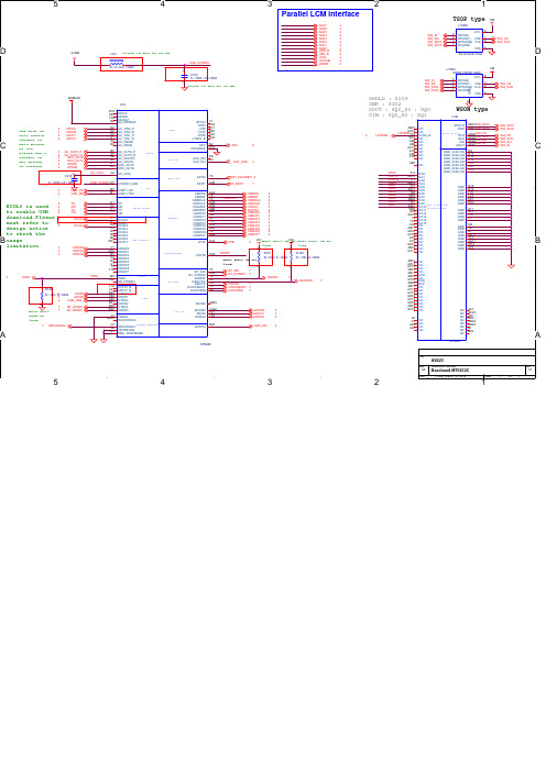
MT6252原理图资料
1
TSOP type
8 1 6 4 SQI_CE SQI_SCK VM
D
VUSB
L101
Close to pin K3 of BB
USB_AVDD33
NC & Serial Flash
D
VM
R / 0 / ohm / 0402 1 C103 C / 1000 / nF / 0402 2
U1005 MX25L12833E MXIC SQI_SI SQI_SO SQI_SIO2 SQI_SIO3 5 2 3 7 VCC DI(DQ0) DO(DQ1) CS# WP#(DQ2) CLK NC(DQ3) VSS GND 9 8 1 6 4
C
The pin1 of C218 should connect to main ground by via. Please don't connect to any ground on surface.
4 4 4 4
MICP0 MICN0 MICP1 MICN1
D2 E2 C2 C1 A3 B3 B7 A7 A6 B5 H1 H2 AU_VCM A4
Baseband MT6252C
Friday, March 16, 2012 Sheet 1 of 7
Rev V1
5
4
3
1
5
4
3
2
1
D
VBAT
TP6
TP7
TP9
TP10
D
If bead is necessary, DCR must be small
R1645 1 1 C203 C / 4700 / nF / 0603 2 1 R1646 R / 0 / ohm / 0402 2 2 R / 0 / ohm / 0402 1 VBAT_RF VBAT_DIGITAL VBAT_ANALOG VBAT_AMP B15 A13 A15 J1 J2 VBAT_RF VBAT_DIGITAL VBAT_ANALOG VBAT_SPK VBAT_SPK VBAT IN
MX25L3205D中文资料
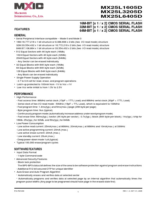
16M-BIT [x 1 / x 2] CMOS SERIAL FLASH 32M-BIT [x 1 / x 2] CMOS SERIAL FLASH 64M-BIT [x 1 / x 2] CMOS SERIAL FLASHFEATURESGENERAL• Serial Peripheral Interface compatible -- Mode 0 and Mode 3• 16M:16,777,216 x 1 bit structure or 8,388,608 x 2 bits (two I/O read mode) structure 32M:33,554,432 x 1 bit structure or 16,772,216 x 2 bits (two I/O read mode) structure 64M:67,108,864 x 1 bit structure or 33,554,432 x 2 bits (two I/O read mode) structure • 512 Equal Sectors with 4K byte each (16Mb)1024 Equal Sectors with 4K byte each (32Mb)2048 Equal Sectors with 4K byte each (64Mb)- Any Sector can be erased individually•32 Equal Blocks with 64K byte each (16Mb)64 Equal Blocks with 64K byte each (32Mb)128 Equal Blocks with 64K byte each (64Mb)- Any Block can be erased individually • Single Power Supply Operation- 2.7 to 3.6 volt for read, erase, and program operations • Latch-up protected to 100mA from -1V to Vcc +1V • Low Vcc write inhibit is from 1.5V to 2.5VPERFORMANCE • High Performance- Fast access time: 86MHz serial clock (15pF + 1TTL Load) and 66MHz serial clock (30pF + 1TTL Load)- Serial clock of two I/O read mode : 50MHz (15pF + TTL Load), which is equivalent to 100MHz - Fast program time: 1.4ms(typ.) and 5ms(max.)/page (256-byte per page)- Byte program time: 9us (typical)- Continuously program mode (automatically increase address under word program mode)- Fast erase time: 60ms(typ.) /sector (4K-byte per sector) ; 0.7s(typ.) /block (64K-byte per block); 14s(typ.) /chip for 16Mb, 25s(typ.) for 32Mb, and 50s(typ.) for 64Mb • Low Power Consumption- Low active read current: 25mA(max.) at 86MHz, 20mA(max.) at 66MHz and 10mA(max.) at 33MHz - Low active programming current: 20mA (max.)- Low active erase current: 20mA (max.)- Low standby current: 20uA (max.)- Deep power-down mode 1uA (typical)• Typical 100,000 erase/program cyclesSOFTWARE FEATURES • Input Data Format- 1-byte Command code •Advanced Security Features - Block lock protectionThe BP0-BP3 status bit defines the size of the area to be software protection against program and erase instructions - Additional 512-bit secured OTP for unique identifier • Auto Erase and Auto Program Algorithm- Automatically erases and verifies data at selected sector- Automatically programs and verifies data at selected page by an internal algorithm that automatically times the program pulse widths (Any page to be programed should have page in the erased state first)MX25L1605D MX25L3205D MX25L6405D元器件交易网•Status Register Feature•Electronic Identification- JEDEC 1-byte manufacturer ID and 2-byte device ID- RES command for 1-byte Device ID- Both REMS and REMS2 commands for 1-byte manufacturer ID and 1-byte device IDHARDWARE FEATURES• SCLK Input- Serial clock input• SI Input- Serial Data Input• SO Output- Serial Data Output• WP#/ACC pin- Hardware write protection and program/erase acceleration• HOLD# pin- pause the chip without diselecting the chip• PACKAGE- 16-pin SOP (300mil)- 8-land WSON (8x6mm or 6x5mm)- 8-pin SOP (200mil, 150mil)- 8-pin PDIP (300mil)- 8-land USON (4x4mm)- All Pb-free devices are RoHS CompliantALTERNATIVE• Security Serial Flash (MX25L1615D/MX25L3215D/MX25L6415D) may provides additional protection features for op-tion. The datasheet is provided under NDA.GENERAL DESCRIPTIONThe MX25L1605D are 16,777,216 bit serial Flash memory, which is configured as 2,097,152 x 8 internally. When it is in two I/O read mode, the structure becomes 8,388,608 bits x 2. The MX25L3205D are 33,554,432 bit serial Flash memory, which is configured as 4,194,304 x 8 internally. When it is in two I/O read mode, the structure becomes 16,772,216 bits x 2. The MX25L6405D are 67,108,864 bit serial Flash memory, which is configured as 8,388,608 x 8 internally. When it is in two I/O read mode, the structure becomes 33,554,432 bits x 2. (please refer to the "Two I/O Read mode" section). The MX25L1605D/3205D/6405D feature a serial peripheral interface and software protocol allowing operation on a simple 3-wire bus. The three bus signals are a clock input (SCLK), a serial data input (SI), and a serial data output (SO). Serial access to the device is enabled by CS# input.When it is in two I/O read mode, the SI pin and SO pin become SIO0 pin and SIO1 pin for address/dummy bits input and data output.The MX25L1605D/3205D/6405D provides sequential read operation on whole chip.After program/erase command is issued, auto program/ erase algorithms which program/ erase and verify the specified page or sector/block locations will be executed. Program command is executed on byte basis, or page (256 bytes) basis, or word basis for Continuously program mode, and erase command is executes on sector (4K-byte), or block (64K-byte), or whole chip basis.To provide user with ease of interface, a status register is included to indicate the status of the chip. The status read command can be issued to detect completion status of a program or erase operation via WIP bit.Advanced security features enhance the protection and security functions, please see security features section for more details.When the device is not in operation and CS# is high, it is put in standby mode and draws less than 20uA DC current. The MX25L1605D/3205D/6405D utilizes MXIC's proprietary memory cell, which reliably stores memory contents even after typical 100,000 program and erase cycles.Table 1. Additional Feature ComparisonPIN CONFIGURATIONSSYMBOL DESCRIPTION CS#Chip SelectSI/SIO0Serial Data Input (for 1 x I/O)/ Serial Data Input & Output (for 2xI/O read mode)SO/SIO1Serial Data Output (for 1 x I/O)/ Serial Data Input & Output (for 2xI/O read mode)SCLK Clock InputWP#/ACCWrite protection: connect to GND ;9.5~10.5V for program/eraseacceleration: connect to 9.5~10.5V HOLD#Hold, to pause the device without deselecting the device VCC + 3.3V Power Supply GNDGroundPIN DESCRIPTION16-PIN SOP (300mil)8-LAND WSON (8x6mm, 6x5mm), USON (4x4mm)8-PIN SOP (200mil, 150mil)PACKAGE OPTIONS16M 32M 64M150mil 8-SOP V 200mil 8-SOP V V 300mil 16-SOP V V V300mil 8-PDIP V V 6x5mm WSON V V 8x6mm WSON V4x4mm USONVV12345678HOLD#VCC NC NC NC NC CS#SO/SIO1161514131211109SCLK SI/SIO0NC NC NC NC GND WP#/ACCCS#SO/SIO1WP#/ACCGND VCC HOLD#SCLK SI/SIO0CS#SO/SIO1WP#/ACC GND VCC HOLD#SCLK SI/SIO01234CS#SO/SIO1WP#/ACC GND 8765VCC HOLD#SCLK SI/SIO08-PIN PDIP (300mil)BLOCK DIAGRAMDATA PROTECTIONThe MX25L1605D/3205D/6405D is designed to offer protection against accidental erasure or programming caused by spurious system level signals that may exist during power transition. During power up the device automatically resets the state machine in the Read mode. In addition, with its control register architecture, alteration of the memory contents only occurs after successful completion of specific command sequences. The device also incorporates several features to prevent inadvertent write cycles resulting from VCC power-up and power-down transition or system noise.•Power-on reset and tPUW: to avoid sudden power switch by system power supply transition, the power-on reset and tPUW (internal timer) may protect the Flash.• Valid command length checking: The command length will be checked whether it is at byte base and completed on byte boundary.• Write Enable (WREN) command: WREN command is required to set the Write Enable Latch bit (WEL) before other command to change data. The WEL bit will return to reset stage under following situation:- Power-up- Write Disable (WRDI) command completion- Write Status Register (WRSR) command completion- Page Program (PP) command completion- Continuously Program mode (CP) instruction completion- Sector Erase (SE) command completion- Block Erase (BE) command completion- Chip Erase (CE) command completion- Write Read-lock Bit (WRLB) instruction completion•Deep Power Down Mode: By entering deep power down mode, the flash device also is under protected from writing all commands except Release from deep power down mode command (RDP) and Read Electronic Signature command (RES).•Advanced Security Features: there are some protection and securuity features which protect content from inadvertent write and hostile access.I. Block lock protection- The Software Protected Mode (SPM) use (BP3, BP2, BP1, BP0) bits to allow part of memory to be protected as read only. The proected area definition is shown as table of "Protected Area Sizes", the protected areas are more flexible which may protect various area by setting value of BP0-BP3 bits.Please refer to table of "protected area sizes".- The Hardware Proteced Mode (HPM) use WP#/ACC to protect the (BP3, BP2, BP1, BP0) bits and SRWD bit.Table 2. Protected Area SizesII. Additional 512-bit secured OTP for unique identifier: to provide 512-bit one-time program area for setting device unique serial number - Which may be set by factory or system customer. Please refer to table 3. 512-bit secured OTP definition.- Security register bit 0 indicates whether the chip is locked by factory or not.- To program the 512-bit secured OTP by entering 512-bit secured OTP mode (with ENSO command), and going through normal program procedure, and then exiting 512-bit secured OTP mode by writing EXSO command.- Customer may lock-down the customer lockable secured OTP by writing WRSCUR(write security register) command to set customer lock-down bit1 as "1". Please refer to table of "security register definition" for security register bit definition and table of "512-bit secured OTP definition" for address range definition.- Note: Once lock-down whatever by factory or customer, it cannot be changed any more. While in 512-bit secured OTP mode, array access is not allowed.Table 3. 512-bit Secured OTP DefinitionAddress range Size Standard Customer LockFactory Lockxxxx00~xxxx0F128-bit ESN (electrical serial number)Determined by customer xxxx10~xxxx3F384-bit N/AHOLD FEATURESHOLD# pin signal goes low to hold any serial communications with the device. The HOLD feature will not stop the operation of write status register, programming, or erasing in progress.The operation of HOLD requires Chip Select(CS#) keeping low and starts on falling edge of HOLD# pin signal while Serial Clock (SCLK) signal is being low (if Serial Clock signal is not being low, HOLD operation will not start until Serial Clock signal being low). The HOLD condition ends on the rising edge of HOLD# pin signal while Serial Clock(SCLK) signal is being low( if Serial Clock signal is not being low, HOLD operation will not end until Serial Clock being low), see Figure 1. Figure 1. Hold Condition OperationThe Serial Data Output (SO) is high impedance, both Serial Data Input (SI) and Serial Clock (SCLK) are don't care during the HOLD operation. If Chip Select (CS#) drives high during HOLD operation, it will reset the internal logic of the device. To re-start communication with chip, the HOLD# must be at high and CS# must be at low.PROGRAM/ERASE ACCELERATIONTo activate the program/erase acceleration function requires ACC pin connecting to 9.5~10.5V voltage (see Figure 2), and then to be followed by the normal program/erase process. By utilizing the program/erase acceleration operation, the performances are improved as shown on table of "ERASE AND PROGRAM PERFORMACE".After power-up ready, it should wait 10ms at least to apply VHH(9.5~10.5V) on the WP#/ACC pin.Figure 2. ACCELERATED PROGRAM TIMING DIAGRAMNote: tVHH (VHH Rise and Fall Time) min. 250nsTable 4. COMMAND DEFINITIONCOMMAND (byte)WREN (writeenable)WRDI (write disable)RDID (read identification )RDSR (read statusregister)WRSR(write status register)READ (read data)FAST READ(fast read data)2READ (2x I/O read command)note1SE (sector erase)1st byte 06 (hex)04 (hex)9F (hex)05 (hex)01 (hex)03 (hex)0B (hex)BB (hex)20 (hex)2nd byte AD1AD1ADD(2)AD13rd byte AD2AD2ADD(2) &Dummy(2)AD24th byte AD3AD3AD35th byte Actionsets the (WEL)write enable latch bit resets the (WEL)write enable latch bitoutputs JEDEC ID:1-byte manufactur er ID & 2-byte device IDto read out the values of the status register to writenew values to the statusregister n bytes read out until CS#goes high n bytes read out until CS#goes high n bytes read out by 2 x I/O until CS#goes high to erase the selectedsector Note 1: The count base is 4-bit for ADD(2) and Dummy(2) because of 2 x I/O. And the MSB is on SI/SIO0 which is different from 1 x I/O conditionCOMMAND (byte)BE (block erase)CE (chip erase)PP (Page program)CP (Continuo-usly program mode)DP (Deep powerdown)RDP (Release from deep power down)RES (read electronic ID)REMS(read electronic manufactu-rer &device ID)REMS2(read ID for 2x I/O mode)1st byte D8 (hex)60 or C7(hex)02 (hex)AD (hex)B9 (hex)AB (hex)AB (hex)90 (hex)EF (hex)2nd byte AD1AD1AD1x x x 3rd byte AD2AD2AD2x x x 4th byte AD3AD3AD3x ADD(note 2)ADD(note2)5th byteAction to erase theselected block to erase whole chip to program the selected page continously program wholechip, theaddress is automatica lly increaseentersdeep power down moderelease from deep power down mode to read out 1-byte device ID outout the manufactu-rer ID &device ID output the manufactu-rer ID &device ID Note 2: ADD=00H will output the manufacturer ID first and ADD=01H will output device ID first Note 3: It is not recommoded to adopt any other code not in the command definition table, which will potentially enter the hidden mode.COMMAND (byte)ENSO (enter secured OTP)EXSO (exit secured OTP)RDSCUR (read security register)WRSCUR (write security register)ESRY (enable SO to output RY/BY#)DSRY (disable SO to output RY/BY#)1st byte B1 (hex)C1 (hex)2B (hex)2F (hex)70 (hex)80 (hex)2nd byte 3rd byte 4th byte 5th byte Actionto enter the 512-bit secured OTP mode to exit the 512-bit secured OTP mode to read value of security registerto set the lock-down bit as "1"(once lock-down,cannot be updated)to enable SO to output RY/BY#during CP mode to disable SO to output RY/BY#during CP modeDummyTable 5-1. Memory Organization (16Mb)Table 5-2. Memory Organization (32Mb)Table 5-3. Memory Organization (64Mb)DEVICE OPERATION1.Before a command is issued, status register should be checked to ensure device is ready for the intended operation.2.When incorrect command is inputted to this LSI, this LSI becomes standby mode and keeps the standby mode until next CS# falling edge. In standby mode, SO pin of this LSI should be High-Z.3.When correct command is inputted to this LSI, this LSI becomes active mode and keeps the active mode until next CS# rising edge.4.Input data is latched on the rising edge of Serial Clock(SCLK) and data shifts out on the falling edge of SCLK. The difference of Serial mode 0 and mode 3 is shown as Figure 3.Figure 3. Serial Modes Supported5.For the following instructions: RDID, RDSR, RDSCUR, READ, FAST_READ, 2READ, RES, REMS and REMS2 the shifted-in instruction sequence is followed by a data-out sequence. After any bit of data being shifted out, the CS# can be high. For the following instructions: WREN, WRDI, WRSR, SE, BE, CE, PP, CP, RDP, DP, ENSO, EXSO,and WRSCUR, the CS# must go high exactly at the byte boundary; otherwise, the instruction will be rejected and not executed.6.During the progress of Write Status Register, Program, Erase operation, to access the memory array is neglected and not affect the current operation of Write Status Register, Program, Erase.Note:CPOL indicates clock polarity of Serial master, CPOL=1 for SCLK high while idle, CPOL=0 for SCLK low while not transmitting. CPHA indicates clock phase. The combination of CPOL bit and CPHA bit decides which Serial mode is supported.SCLKMSBCPHASI 01CPOL 0(Serial mode 0)(Serial mode 3)1SO SCLKMSBCOMMAND DESCRIPTION(1) Write Enable (WREN)The Write Enable (WREN) instruction is for setting Write Enable Latch (WEL) bit. For those instructions like PP, CP, SE, BE, CE, and WRSR, which are intended to change the device content, should be set every time after the WREN instruction setting the WEL bit.The sequence of issuing WREN instruction is: CS# goes low-> sending WREN instruction code-> CS# goes high. (see Figure 12)(2) Write Disable (WRDI)The Write Disable (WRDI) instruction is for resetting Write Enable Latch (WEL) bit.The sequence of issuing WRDI instruction is: CS# goes low-> sending WRDI instruction code-> CS# goes high. (see Figure 13)The WEL bit is reset by following situations:- Power-up- Write Disable (WRDI) instruction completion- Write Status Register (WRSR) instruction completion- Page Program (PP) instruction completion- Sector Erase (SE) instruction completion- Block Erase (BE) instruction completion- Chip Erase (CE) instruction completion- Continuously program mode (CP) instruction completion(3) Read Identification (RDID)The RDID instruction is for reading the manufacturer ID of 1-byte and followed by Device ID of 2-byte. The MXIC Manufacturer ID is C2(hex), the memory type ID is 20(hex) as the first-byte device ID, and the individual device ID of second-byte ID are listed as table of "ID Definitions".The sequence of issuing RDID instruction is: CS# goes low-> sending RDID instruction code -> 24-bits ID data out on SO -> to end RDID operation can use CS# to high at any time during data out. (see Figure. 14)While Program/Erase operation is in progress, it will not decode the RDID instruction, so there's no effect on the cycle of program/erase operation which is currently in progress. When CS# goes high, the device is at standby stage.(4) Read Status Register (RDSR)The RDSR instruction is for reading Status Register Bits. The Read Status Register can be read at any time (even in program/erase/write status register condition) and continuously. It is recommended to check the Write in Progress (WIP) bit before sending a new instruction when a program, erase, or write status register operation is in progress.The sequence of issuing RDSR instruction is: CS# goes low-> sending RDSR instruction code-> Status Register data out on SO (see Figure. 15)The definition of the status register bits is as below:WIP bit. The Write in Progress (WIP) bit, a volatile bit, indicates whether the device is busy in program/erase/write status register progress. When WIP bit sets to 1, which means the device is busy in program/erase/write status register progress. When WIP bit sets to 0, which means the device is not in progress of program/erase/write status register cycle.WEL bit. The Write Enable Latch (WEL) bit, a volatile bit, indicates whether the device is set to internal write enable latch. When WEL bit sets to 1, which means the internal write enable latch is set, the device can accept program/erase/write status register instruction. When WEL bit sets to 0, which means no internal write enable latch; the device will not accept program/erase/write status register instruction. The program/erase command will be ignored and not affect value of WEL bit if it is applied to a protected memory area.BP3, BP2, BP1, BP0 bits. The Block Protect (BP3, BP2, BP1, BP0) bits, non-volatile bits, indicate the protected area(as defined in table 1) of the device to against the program/erase instruction without hardware protection mode being set. To write the Block Protect (BP3, BP2, BP1, BP0) bits requires the Write Status Register (WRSR) instruction to be executed. Those bits define the protected area of the memory to against Page Program (PP), Sector Erase (SE), Block Erase (BE) and Chip Erase(CE) instructions (only if all Block Protect bits set to 0, the CE instruction can be executed).Continuously Program Mode( CP mode) bit. The Continuously Program Mode bit indicates the status of CP mode, "0" indicates not in CP mode; "1" indicates in CP mode.SRWD bit. The Status Register Write Disable (SRWD) bit, non-volatile bit, is operated together with Write Protection (WP#/ ACC) pin for providing hardware protection mode. The hardware protection mode requires SRWD sets to 1 and WP#/ACC pin signal is low stage. In the hardware protection mode, the Write Status Register (WRSR) instruction is no longer accepted for execution and the SRWD bit and Block Protect bits (BP3, BP2, BP1, BP0) are read only.Status Registernote1: see the table "Protected Area Sizes"(5) Write Status Register (WRSR)The WRSR instruction is for changing the values of Status Register Bits. Before sending WRSR instruction, the Write Enable (WREN) instruction must be decoded and executed to set the Write Enable Latch (WEL) bit in advance. The WRSR instruction can change the value of Block Protect (BP3, BP2, BP1, BP0) bits to define the protected area of memory (as shown in table 1). The WRSR also can set or reset the Status Register Write Disable (SRWD) bit in accordance with Write Protection (WP#/ACC) pin signal. The WRSR instruction cannot be executed once the Hardware Protected Mode (HPM)is entered.The sequence of issuing WRSR instruction is: CS# goes low-> sending WRSR instruction code-> Status Register data on SI-> CS# goes high. (see Figure 16)The WRSR instruction has no effect on b6, b1, b0 of the status register.The CS# must go high exactly at the byte boundary; otherwise, the instruction will be rejected and not executed. The self-timed Write Status Register cycle time (tW) is initiated as soon as Chip Select (CS#) goes high. The Write in Progress (WIP) bit still can be check out during the Write Status Register cycle is in progress. The WIP sets 1 during the tW timing,and sets 0 when Write Status Register Cycle is completed, and the Write Enable Latch (WEL) bit is reset.Table 6. Protection ModesNote:1. As defined by the values in the Block Protect (BP3, BP2, BP1, BP0) bits of the Status Register, as shown in Table 1.As the above table showing, the summary of the Software Protected Mode (SPM) and Hardware Protected Mode (HPM).Software Protected Mode (SPM):-When SRWD bit=0, no matter WP#/ACC is low or high, the WREN instruction may set the WEL bit and can changethe values of SRWD, BP3, BP2, BP1, BP0. The protected area, which is defined by BP3, BP2, BP1, BP0, is at software protected mode (SPM).-When SRWD bit=1 and WP#/ACC is high, the WREN instruction may set the WEL bit can change the values of SRWD,BP3, BP2, BP1, BP0. The protected area, which is defined by BP3, BP2, BP1, BP0, is at software protected mode (SPM)ModeStatus register condition Software protection mode(SPM)Status register can be written in (WEL bit is set to "1") and the SRWD, BP0-BP3bits can be changedWP# and SRWD bit status MemoryWP#=1 and SRWD bit=0, or WP#=0 and SRWD bit=0, or WP#=1 and SRWD=1The protected area cannot be program or erase.The protected area cannot be program or erase.WP#=0, SRWD bit=1The SRWD, BP0-BP3 ofstatus register bits cannot be changedHardware protection mode (HPM)Note: If SRWD bit=1 but WP#/ACC is low, it is impossible to write the Status Register even if the WEL bit has previously been set. It is rejected to write the Status Register and not be executed.Hardware Protected Mode (HPM):-When SRWD bit=1, and then WP#/ACC is low (or WP#/ACC is low before SRWD bit=1), it enters the hardware protected mode (HPM). The data of the protected area is protected by software protected mode by BP3, BP2, BP1, BP0 and hardware protected mode by the WP#/ACC to against data modification.Note: to exit the hardware protected mode requires WP#/ACC driving high once the hardware protected mode is entered. If the WP#/ACC pin is permanently connected to high, the hardware protected mode can never be entered; only can use software protected mode via BP3, BP2, BP1, BP0.(6) Read Data Bytes (READ)The read instruction is for reading data out. The address is latched on rising edge of SCLK, and data shifts out on the falling edge of SCLK at a maximum frequency fR. The first address byte can be at any location. The address is automatically increased to the next higher address after each byte data is shifted out, so the whole memory can be read out at a single READ instruction. The address counter rolls over to 0 when the highest address has been reached.The sequence of issuing READ instruction is: CS# goes low-> sending READ instruction code-> 3-byte address on SI -> data out on SO-> to end READ operation can use CS# to high at any time during data out. (see Figure. 17)(7) Read Data Bytes at Higher Speed (FAST_READ)The FAST_READ instruction is for quickly reading data out. The address is latched on rising edge of SCLK, and data of each bit shifts out on the falling edge of SCLK at a maximum frequency fC. The first address byte can be at any location. The address is automatically increased to the next higher address after each byte data is shifted out, so the whole memory can be read out at a single FAST_READ instruction. The address counter rolls over to 0 when the highest address has been reached.The sequence of issuing FAST_READ instruction is: CS# goes low-> sending FAST_READ instruction code-> 3-byte address on SI-> 1-dummy byte address on SI->data out on SO-> to end FAST_READ operation can use CS# to high at any time during data out. (see Figure. 18)While Program/Erase/Write Status Register cycle is in progress, FAST_READ instruction is rejected without any impact on the Program/Erase/Write Status Register current cycle.(8) 2 x I/O Read Mode (2READ)The 2READ instruction enable double throughput of Serial Flash in read mode. The address is latched on rising edge of SCLK, and data of every two bits(interleave on 2 I/O pins) shift out on the falling edge of SCLK at a maximum frequency fT. The first address byte can be at any location. The address is automatically increased to the next higher address after each byte data is shifted out, so the whole memory can be read out at a single 2READ instruction. The address counter rolls over to 0 when the highest address has been reached. Once writing 2READ instruction, the following address/dummy/ data out will perform as 2-bit instead of previous 1-bit.The sequence of issuing 2READ instruction is: CS# goes low→ sending 2READ instruction→ 24-bit address interleave on SIO1 & SIO0→ 8-bit dummy interleave on SIO1 & SIO0→ data out interleave on SIO1 & SIO0→ to end 2READ operation can use CS# to high at any time during data out (see Figure of 2 x I/O Read Mode Timing Waveform)While Program/Erase/Write Status Register cycle is in progress, 2READ instruction is rejected without any impact on the Program/Erase/Write Status Register current cycle.The 2 I/O only perform read operation. Program/Erase /Read ID/Read status/Read ID....operation do not support 2 I/O throughputs.(9) Sector Erase (SE)The Sector Erase (SE) instruction is for erasing the data of the chosen sector to be "1". The instruction is used for any 4K-byte sector. A Write Enable (WREN) instruction must execute to set the Write Enable Latch (WEL) bit before sending the Sector Erase (SE). Any address of the sector (see table 3) is a valid address for Sector Erase (SE) instruction. The CS# must go high exactly at the byte boundary (the latest eighth of address byte been latched-in); otherwise, the instruction will be rejected and not executed.Address bits [Am-A12] (Am is the most significant address) select the sector address.The sequence of issuing SE instruction is: CS# goes low -> sending SE instruction code-> 3-byte address on SI -> CS# goes high. (see Figure 22)The self-timed Sector Erase Cycle time (tSE) is initiated as soon as Chip Select (CS#) goes high. The Write in Progress (WIP) bit still can be check out during the Sector Erase cycle is in progress. The WIP sets 1 during the tSE timing, and sets 0 when Sector Erase Cycle is completed, and the Write Enable Latch (WEL) bit is reset. If the page is protected by BP3, BP2, BP1, BP0 bits, the Sector Erase (SE) instruction will not be executed on the page.(10) Block Erase (BE)The Block Erase (BE) instruction is for erasing the data of the chosen block to be "1". The instruction is used for 64K-byte sector erase operation. A Write Enable (WREN) instruction must execute to set the Write Enable Latch (WEL) bit before sending the Block Erase (BE). Any address of the block (see table 3) is a valid address for Block Erase (BE) instruction. The CS# must go high exactly at the byte boundary (the latest eighth of address byte been latched-in); otherwise, the instruction will be rejected and not executed.The sequence of issuing BE instruction is: CS# goes low -> sending BE instruction code-> 3-byte address on SI -> CS# goes high. (see Figure 23)The self-timed Block Erase Cycle time (tBE) is initiated as soon as Chip Select (CS#) goes high. The Write in Progress (WIP) bit still can be check out during the Sector Erase cycle is in progress. The WIP sets 1 during the tBE timing, and sets 0 when Sector Erase Cycle is completed, and the Write Enable Latch (WEL) bit is reset. If the page is protected by BP3, BP2, BP1, BP0 bits, the Block Erase (BE) instruction will not be executed on the page.(11) Chip Erase (CE)The Chip Erase (CE) instruction is for erasing the data of the whole chip to be "1". A Write Enable (WREN) instruction must execute to set the Write Enable Latch (WEL) bit before sending the Chip Erase (CE). Any address of the sector (see table 3) is a valid address for Chip Erase (CE) instruction. The CS# must go high exactly at the byte boundary( the latest eighth of address byte been latched-in); otherwise, the instruction will be rejected and not executed.The sequence of issuing CE instruction is: CS# goes low-> sending CE instruction code-> CS# goes high. (see Figure 24)。
RTS5822_QFN+NT99141_CSP推荐线路
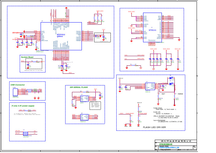
GND
1K5 1K5 4K7 R0402 R0402 R0402 SDA SCL SSOR_RESET
E2 E3 E5 E6 D8 E8 E1 E7 SSOR_VDDIO
AVDD AVDD AVDD AVDD AVDDPIX AGNDPIX AGND AGND
MCLK PCLK HREF VSYNC D0 D1 D2 D3 D4 D5 D6 D7 D8 D9 SDTAT SCLK PWRDN RESETN GPI NC NC NC NC NC
Support List: MXIC,MX25L512 EON, EN25F05 PMC, PM25LV512 ATMEL,AT25F512 AMIC, A25L512
4.7uF C0603
1 2 3 FLASH_MODE 4 FLASH_ENABLE 5
VIN C1 C2 FLASH EN SGM3140 SGM3140
close to IC
R7 C15 EC1 2.2uF C0603
0.1uF C0402
Capacitor must be 0.1u for RST#
20pF/NC 0R C0402 R0402 HCLK D2 VBUS_IN U3 A D1 VOUT PGND SGND FB RESET 10 9 8 7 6 VI_FLASH A C18 1uF C0603 K
VO_FLASH
1
R12
RSET
1
R13
RSENSE
B
connector 88460-0500
100K(1%) R0402
0.47R R0603
2
KH25L5121E SOP-8
VBUS_IN 1
If only 3.3V power supply
MX29GL256EHT2I-90Q
现货库存、技术资料、百科信息、热点资讯,精彩尽在鼎好!MX29L1611G / MX29L1611*16M-BIT [2M x 8/1M x 16] CMOSSINGLE VOLTAGE FLASH EEPROMADVANCED INFORMATION•Status Register feature for detection of program orerase cycle completion•Low VCC write inhibit is equal to or less than 1.8V•Software data protection•Page program operation- Internal address and data latches for 64 words perpage- Page programming time: 5ms typical•Low power dissipation- 50mA active current- 20uA standby current•Two independently Protected sectors•Package type- 42 pin plastic DIP* For page mode read onlyGENERAL DESCRIPTIONThe MX29L1611G is a 16-mega bit Flash memory organized as either 1M wordx16 or 2M bytex8. The MX29L1611G includes 32 sectors of 64KB(65,536 Bytes or 32,768 words). MXIC's Flash memories offer the most cost-effective and reliable read/write non-volatile random access memory. The MX29L1611G is packaged in 42 pin PDIP.The standard MX29L1611G offers access times as fast as 100ns,allowing operation of high-speed microprocessors without wait. To eliminate bus contention, the MX29L1611G has separate chip enable CE and, output enable (OE).MXIC's Flash memories augment EPROM functionality with electrical erasure and programming. The MX29L1611G uses a command register to manage this functionality.MX29L1611G does require high input voltages for programming. Commands require 11V input to determine the operation of the device. Reading data out of the device is similar to reading from an EPROM.MXIC Flash technology reliably stores memory contents even after 100 cycles. The MXIC's cell is designed to optimize the erase and programming mechanisms. In addition, the combination of advanced tunnel oxide processing and low internal electric fields for erase and programming operations produces reliable cycling. The MX29L1611G uses a 11V Vpp supply to perform the Auto Erase and Auto Program algorithms.The highest degree of latch-up protection is achieved with MXIC's proprietary non-epi process. Latch-up protection is proved for stresses up to 100 milliamps on address and data pin from -1V to VCC +1V.FEATURES•3.3V ± 10% for write and read operation•11V Vpp erase/programming operation •Endurance: 100 cycles•Fast random access time: 90ns/100ns/120ns •Fast page access time: 30ns (Only for 29L1611PC-90/ 10/12)•Sector erase architecture- 32 equal sectors of 64k bytes each- Sector erase time: 200ms typical•Auto Erase and Auto Program Algorithms- Automatically erases any one of the sectors or the whole chip- Automatically programs and verifies data at specified addressesPIN CONFIGURATIONS 42 PDIP PIN DESCRIPTIONSYMBOL PIN NAMEA0 - A19Address InputQ0 - Q14Data Input/OutputQ15/A-1Q15(Word mode)/LSB addr.(Bytemode, for read mode only)CE Chip Enable InputOE Output Enable InputBYTE/VPP Word/Byte Selection Input, Erase/Program supply voltageVCC Power SupplyGND Ground Pin1 2 3 4 5 6 7 8 9 10 11 12 13 14 15 16 17 18 19 20 2142 41 40 39 38 37 36 35 34 33 32 31 30 29 28 27 26 25 24 23 22A18 A17 A7 A6 A5 A4 A3 A2 A1 A0 CE GND OE Q0 Q8 Q1 Q9 Q2 Q10 Q3 Q11A19A8A9A10A11A12A13A14A15A16BYTE/VPPGNDQ15/A-1Q7Q14Q6Q13Q5Q12Q4VCCMX29L1611GTable1. PIN DESCRIPTIONSSYMBOL TYPE NAME AND FUNCTIONA0 - A19INPUT ADDRESS INPUTS: for memory addresses. Addresses are internally latchedduring a write cycle.Q0 - Q7INPUT/OUTPUT LOW-BYTE DATA BUS: Input data and commands during Command InterfaceRegister(CIR) write cycles. Outputs array,status and identifier data in theappropriate read mode. Floated when the chip is de-selected or the outputs aredisabled.Q8 - Q14INPUT/OUTPUT HIGH-BYTE DATA BUS: Inputs data during x 16 Data-Write operations.Outputs array, identifier data in the appropriate read mode; not used for statusregister reads. Floated when the chip is de-selected or the outputs are disabled Q15/A -1INPUT/OUTPUT Selects between high-byte data INPUT/OUTPUT(BYTE = HIGH) and LSBADDRESS(BYTE = LOW) for raed operation.CE INPUT CHIP ENABLE INPUTS: Activate the device's control logic, Input buffers,decoders and sense amplifiers. With CE high, the device is deselected andpower consumption reduces to Standby level upon completion of any currentprogram or erase operations. CE must be low to select the device.OE INPUT OUTPUT ENABLES: Gates the device's data through the output buffers duringa read cycle OE is active low.BYTE/VPP INPUT BYTE ENABLE: While operating read mode, BYTE Low places device in x8mode. All data is then input or output on Q0-7 and Q8-14 float. AddressQ15/A-1 selects between the high and low byte. While operating read mode, BYTEhigh places the device in x16 mode, and turns off the Q15/A-1 input buffer.Address A0, then becomes the lowest order address.ERASE/PROGRAM ENABLE:When BYTE/VPP=11V would place this deviceinto ERASE/PROGRAM mode.VCC DEVICE POWER SUPPLY(3.3V ± 10%)GND GROUNDBUS OPERATIONFlash memory reads, erases and writes in-system via the local CPU . All bus cycles to or from the flash memory conform to standard microprocessor bus cycles.Table 2.1 Bus Operations for Word-Wide Mode (BYTE/VPP = VIH)Mode Notes CE OE BYTE/VPP A0A1A9Q0-Q7Q8-Q14Q15/A-1 Read1VIL VIL VIH X X X DOUT DOUT DOUT Output Disable1VIL VIH VIH X X X High Z High Z HighZ Standby1VIH X H/L X X X High Z HIgh Z HighZ Manufacturer ID2,4VIL VIL VIH VIL VIL VID C2H00H0B Device ID2,4VIL VIL VIH VIH VIL VID F6H00H0B Write1,3,5VIL VIH VPP X X X DIN DIN DINTable2.2 Bus Operations for Byte-Wide Mode (BYTE = VIL)Mode Notes CE OE BYTE/VPP A0A1A9Q0-Q7Q8-Q14Q15/A-1 Read1VIL VIL VIL X X X DOUT HighZ VIL/VIH Output Disable1VIL VIH VIL X X X High Z High Z XStandby1VIH X H/L X X X High Z HIgh Z XManufacturer ID2,4VIL VIL VIL VIL VIL VID C2H High Z VIL Device ID2,4VIL VIL VIL VIH VIL VID F6H High Z VIL Write1,3,5VIL VIH VPP X X X DIN DIN DINNOTES :1.X can be VIH or VIL for address or control pins.2.A0 and A1 at VIL provide manufacturer ID codes. A0 at VIH and A1 at VIL provide device ID codes. A0 at VIL,A1 at VIH and with appropriate sector addresses provide Sector Protect Code.(Refer to Table 4),A2~A19=Do not care.3. Commands for different Erase operations, Data program operations or Sector Protect operations can only besuccessfully completed through proper command sequence.4.VID = 11.5V- 12.5V5.Word mode only for write operation VPP=10.5V~11.5VTABLE 3. COMMAND DEFINITIONS(BYTE/VPP=VHH)Command Read/Silicon Page Chip Sector Read Clear Sequence Reset ID Read Program Erase Erase Status Reg.Status Reg.Bus Write 4446643Cycles Req'd First Bus Addr 5555H 5555H 5555H 5555H 5555H 5555H 5555H Write Cycle Data AAH AAH AAH AAH AAH AAH AAH Second Bus Addr 2AAAH 2AAAH 2AAAH 2AAAH 2AAAH 2AAAH 2AAAH Write Cycle Data 55H 55H 55H 55H 55H 55H 55H Third Bus Addr 5555H 5555H 5555H 5555H 5555H 5555H 5555H Write Cycle Data F0H 90H A0H 80H 80H 70H 50HFourth Bus Addr RA 00H/01H PA 5555H 5555H X Read/Write Cycle Data RDC2H/F6HPDAAH AAH SRDFifth Bus Addr 2AAAH 2AAAH Write Cycle Data 55H 55H Sixth Bus Addr 5555H SA Write CycleData10H30HWRITE OPERATIONSCommands are written to the COMMAND INTERFACE REGISTER (CIR) using standard microprocessor write timings. The CIR serves as the interface between the microprocessor and the internal chip operation. The CIR can decipher Read Array, Read Silicon ID, Erase and Program command. In the event of a read command, the CIR simply points the read path at either the array or the silicon ID, depending on the specific read command given. For a program or erase cycle, the CIR informs the write state machine that a program or erase has been requested. During a program cycle, the write state machine will control the program sequences and the CIRwill only respond to status reads. During a sector/chip erase cycle, the CIR will respond to status reads. After the write state machine has completed its task, it will allow the CIR to respond to its full command set. The CIR stays at read status register mode until the microprocessor issues another valid command sequence.Device operations are selected by writing commands into the CIR. Table 3 below defines 16 Mbit flash family command.TABLE 3. COMMAND DEFINITIONSCommand Sector Sector Verify Sector AbortSequence Protection Unprotect ProtectBus Write6643Cycles Req'dFirst Bus Addr5555H5555H5555H5555HWrite Cycle Data AAH AAH AAH AAHSecond Bus Addr2AAAH2AAAH2AAAH2AAAHWrite Cycle Data55H55H55H55HThird Bus Addr5555H5555H5555H5555HWrite Cycle Data60H60H90H E0HFourth Bus Addr5555H5555H SA**Read/Write Cycle Data AAH AAH C2H*Fifth Bus Addr2AAAH2AAAHWrite Cycle Data55H55HSixth Bus Addr SA**SA**Write Cycle Data20H40HNotes:1. Address bit A15 -- A19 = X = Don't care for all address commands except for Program Address(PA) and Sector Address(SA). 5555H and 2AAAH address command codes stand for Hex number starting from A0 to A14.2. Bus operations are defined in Table 2.3. RA = Address of the memory location to be read.PA = Address of the memory location to be programmed. Addresses are latched on the falling edge of the CE pulse.SA = Address of the sector to be erased. The combination of A15 -- A19 will uniquely select any sector.4. RD = Data read from location RA during read operation.PD = Data to be programmed at location PA. Data is latched on the rising edge of CE.SRD = Data read from status register.5. Only Q0-Q7 command data is taken, Q8-Q15 = Don't care.* Refer to Table 4, Figure 11.** Only the top and the bottom sectors have protect- bit feature. SA = (A19,A18,A17,A16,A15) = 00000B or 11111B is valid.READ/RESET COMMANDThe read or reset operation is initiated by writing the read/ reset command sequence into the command register. Microprocessor read cycles retrieve array data from the memory. The device remains enabled for reads until the CIR contents are altered by a valid command sequence. The device will automatically power-up in the read/reset state. In this case, a command sequence is not required for "read operation". Standard microprocessor read cycles will retrieve array data. This default value ensures that no spurious alteration of the memory content occurs during the power transition. Refer to the AC Read Characteristics and Waveforms for the specific timing parameters.The MX29L1611G is accessed like an EPROM. When CE and OE are low the data stored at the memory location determined by the address pins is asserted on the outputs. The outputs are put in the high impedance state whenever CE or OE is high. This dual line control gives designers flexibility in preventing bus contention.Note that the read/reset command is not valid when program or erase is in progress.PAGE READThe MX29L1611G offers "fast page mode read" function. The users can take the access time advantage if keeping CE, OE at low and the same page address (A3~A19 unchanged). Please refer to Figure 5-2 for detailed timing waveform. The system performance could be enhanced by initiating 1 normal read and 7 fast page reads(for word mode A0~A2) or 15 fast page reads(for byte mode altering A-1~A2).PAGE PROGRAMThe device is set up in the programming mode when VPP=11V is applied OE=VIH.To initiate Page program mode, a three-cycle command sequence is required. There are two "unlock" write cycles. These are followed by writing the page program command-A0H.Any attempt to write to the device without the three-cycle command sequence will not start the internal Write State Machine(WSM), no data will be written to the device. After three-cycle command sequence is given, a byte(word) load is performed by applying a low pulse on the CE input with CE low and OE high. The address is latched on the falling edge of CE. The data is latched by the first rising edge of CE. Maximum of 64 words of data may be loaded into each page by the same procedure as outlined in the page program section below.PROGRAMAny page to be programmed should have the page in the erased state first, i.e. performing sector erase is suggested before page programming can be performed.The device is programmed on a page basis. If a word of data within a page is to be changed, data for the entire page can be loaded into the device. Any word that is not loaded during the programming of its page will be still in the erased state (i.e. FFH). Once the words of a page are loaded into the device, they are simultaneously programmed during the internal programming period. After the first data word has been loaded into the device, successive words are entered in the same manner. Each new word to be programmed must have its high to low transition on CE within 30us of the low to high transition of CE of the preceding word. A6 to A19 specify the page address, i.e., the device is page-aligned on 64 words boundary. The page address must be valid during each high to low transition of CE. A0 to A5 specify the word address withih the page. The word may be loaded in any order; sequential loading is not required. If a high to low transition of CE is not detected whithin 100us of the last low to high transition, the load period will end and the internal programming period will start. The Auto page program terminates when status on Q7 is '1' at which time the device stays at read status register mode until the CIR contents are altered by a valid command sequence.(Refer to table 3,6 and Figure 1,7,8)CHIP ERASEThe device is set up in the erase mode when VPP=11V is applied OE=VIH.Chip erase is a six-bus cycle operation. There are two "unlock" write cycles. These are followed by writing theSECTOR ERASESector erase is a six-bus cycle operation. There are two "unlock" write cycles. These are followed by writing the set-up command-80H. Two more "unlock" write cycles are then followed by the sector erase command-30H.The sector address is latched on the falling edge of CE,while the command (data) is latched on the rising edge of CE.Sector erase does not require the user to program the device prior to erase. The system is not required to provide any controls or timings during these operations.The automatic sector erase begins on the rising edge of the last CE pulse in the command sequence and terminates when the status on Q7 is "1" at which time the device stays at read status register mode. The device remains enabled for read status register mode until the CIR contents are altered by a valid command sequence.(Refer to table 3,6 and Figure 3,4,6,8)A19A18A17A16A15Address Range[A19, -1]SA000000000000H--00FFFFH SA100001010000H--01FFFFH SA200010020000H--02FFFFH SA300011030000H--03FFFFH SA400100040000H--04FFFFH ............... ................................SA31111111F0000H--1FFFFFHTable 5. MX29L1611G Sector Address Table(Byte-Wide Mode)READ STATUS REGISTERThe MXIC's 16 Mbit flash family contains a status register which may be read to determine when a program or erase operation is complete, and whether that operation completed successfully. The status register may be read at any time by writing the Read Status command to the CIR. After writing this command, all subsequent read operations output data from the status register until another valid command sequence is written to the CIR.A Read Array command must be written to the CIR to return to the Read Array mode.The status register bits are output on Q3 - Q7(table 6)whether the device is in the byte-wide (x8) or word-wide (x16) mode for the MX29L1611G. In the word-wide mode the upper byte, Q(8:15) is set to 00H during a Read Status command. In the byte-wide mode, Q(8:14) are tri-stated and Q15/A-1 retains the low order address function.It should be noted that the contents of the status register are latched on the falling edge of OE or CE whichever occurs last in the read cycle. This prevents possible bus errors which might occur if the contents of the status register change while reading the status register. CE or OE must be toggled with each subsequent status read,or the completion of a program or erase operation will not be evident.The Status Register is the interface between the microprocessor and the Write State Machine (WSM).When the WSM is active, this register will indicate the status of the WSM, and will also hold the bits indicating whether or not the WSM was successful in performing the desired operation. The WSM sets status bits four through seven and clears bits six and seven, but cannot clear status bits four and five. If Erase fail or Program fail status bit is detected, the Status Register is not cleared until the Clear Status Register command is written. The MX29L1611G automatically outputs Status Register data when read after Chip Erase, Sector Erase, Page Program or Read Status Command write cycle. The default state of the Status Register after powerup and return from deep power-down mode is (Q7, Q6, Q5, Q4) = 1000B. Q3 = 0or 1 depends on sector-protect status, can not be changed by Clear Status Register Command or Write State Machine."set-up" command-80H. Two more "unlock" write cycles are then followed by the chip erase command-10H.Chip erase does not require the user to program the device prior to erase.The automatic erase begins on the rising edge of the last CE pulse in the command sequence and terminates when the status on Q7 is "1" at which time the device stays at read status register mode. The device remains enabled for read status register mode until the CIR contents are altered by a valid command sequence.(Refer to table 3,6 and Figure 2,6,8)CLEAR STATUS REGISTERThe Eraes fail status bit (Q5) and Program fail status bit (Q4) are set by the write state machine, and can only be reset by the system software. These bits can indicate various failure conditions(see Table 6). By allowing the system software to control the resetting of these bits, several operations may be performed (such as cumulatively programming several pages or erasing multiple blocks in squence). The status register may then be read to determine if an error occurred during that programming or erasure series. This adds flexibility to the way the device may be programmed or erased. Additionally, once the program(erase) fail bit happens, the program (erase) operation can not be performed further. The program(erase) fail bit must be reset by system software before further page program or sector (chip) erase are attempted. To clear the status register, the Clear Status Register command is written to the CIR. Then, any other command may be issued to the CIR. Note again that before a read cycle can be initiated, a Read command must be written to the CIR to specify whether the read data is to come from the Array, Status Register or Silicon ID.TABLE 6. MX29L1611G STATUS REGISTERSTATUS NOTES Q7Q6Q5Q4Q3 IN PROGRESS PROGRAM1,2,500000/1 ERASE1,3,500000/1 COMPLETE PROGRAM1,2,510000/1 ERASE1,3,510000/1 FAIL PROGRAM1,4,510010/1 ERASE1,4,510100/1 AFTER CLEARING STATUS REGISTER510000/1NOTES:1. Q7 : WRITE STATE MACHINE STATUS1 = READY, 0 = BUSYQ5 : ERASE FAIL STATUS1 = FAIL IN ERASE, 0 = SUCCESSFUL ERASEQ4 : PROGRAM FAIL STATUS1 = FAIL IN PROGRAM, 0 = SUCCESSFUL PROGRAMQ3 : SECTOR-PROTECT STATUS1 = SECTOR 0 OR/AND 15 PROTECTED0 = NONE OF SECTOR PROTECTEDQ6,Q2 - 0 = RESERVED FOR FUTURE ENHANCEMENTS.These bits are reserved for future use ; mask them out when polling the Status Register.2. PROGRAM STATUS is for the status during Page Programming or Sector Unprotect mode.3. ERASE STATUS is for the status during Sector/Chip Erase or Sector Protection mode.4. FAIL STATUS bit(Q4 or Q5) is provided during Page Program or Sector/Chip Erase modes respectively.5. Q3 = 0 or1 depends on Sector-Protect Status.The device remains enabled for read status register mode until the CIR contents are altered by a valid command sequence.ABORT MODETo activate Abort mode, a three-bus cycle operation is required. The E0H command (Refer to table 3) only stops Page program or Sector /Chip erase operation currently in progress and puts the device in Abort mode. So the program or erase operation will not be completed. Since the data in some page/sectors is no longer valid due to an incomplete program or erase operation, the program fail (Q4) or erase fail (Q5)bit will be set.A read array command MUST be written to bring the device out of the abort state without incurring any wake up latency. Note that once device is brought out, Clear status register mode is required before a program or erase operation can be executed.SECTOR PROTECTIONTo activate this mode, a six-bus cycle operation and VPP=11V are required. There are two 'unlock' write cycles. These are followed by writing the 'set-up'command. Two more 'unlock' write cycles are then followed by the Lock Sector command - 20H. Sector address is latched on the falling edge of CE of the sixth cycle of the command sequence. The automatic Lock operation begins on the rising edge of the last CE pulse in the command sequence and terminates when the Status on Q7 is '1' at which time the device stays at the read status register mode.The device remains enabled for read status register mode until the CIR contents are altered by a valid command sequence (Refer to table 3,6 and Figure 9,11).VERIFY SECTOR PROTECTTo verify the Protect status of the Top and the Bottom sector, operation is initiated by writing Silicon ID read command into the command register. Following the command write, a read cycle from address XX00H retrieves the Manufacturer code of C2H. A read cycle from XX01H returns the Device code F8H. A read cycle from appropriate address returns information as to which sectors are protected. To terminate the operation, it is necessary to write the read/reset command sequence into the CIR.(Refer to table 3,4 and Figure 11)A few retries are required if Protect status can not be verified successfully after each operation.SECTOR UNPROTECTIt is also possible to unprotect the sector , same as the first five write command cycles in activating sector protection mode followed by the Unprotect Sector command -40H, the automatic Unprotect operation begins on the rising edge of the last CE pulse in the command sequence and terminates when the Status on DQ7 is '1'at which time the device stays at the read status register mode.(Refer to table 3,6 and Figure 10,11)DATA PROTECTIONThe MX29L1611G is designed to offer protection against accidental erasure or programming caused by spurious system level signals that may exist during power transitions. During power up the device automatically resets the internal state machine in the Read Array mode.Also, with its control register architecture, alteration of the memory contents only occurs after successful completion of specific multi-bus cycle command sequences.The device also incorporates several features to prevent inadvertent write cycles resulting from VCC power-up and power-down transitions or system noise.LOW VCC WRITE INHIBITTo avoid initiation of a write cycle during VCC power-up and power-down, a write cycle is locked out for VCC less than VLKO(typically 1.8V). If VCC < VLKO, the command register is disabled and all internal program/erase circuits are disabled. Under this condition the device will reset to the read mode. Subsequent writes will be ignored until the VCC level is greater than VLKO. It is the user's responsibility to ensure that the control pins are logically correct to prevent unintentional write when VCC is above VLKO.WRITE PULSE "GLITCH" PROTECTION Noise pulses of less than 10ns (typical) on CE will not initiate a write cycle.LOGICAL INHIBITWriting is inhibited by holding any one of OE = VIL,CE = VIH. To initiate a write cycle, CE must be a logical zero while OE is a logical one, and VPP=11V should be applied.DC CHARACTERISTICS VCC = 3.3V±10%SYMBOL PARAMETER NOTES MIN.TYP.MAX.UNITS TEST CONDITIONS IIL Input Load1±1uA VCC=VCC Max Current VIN=VCC or GND ILO Output Leakage1±10uA VCC=VCC Max Current VIN=VCC or GND ISB1VCC Standby12050uA VCC=VCC Max Current(CMOS)CE=VCC ± 0.2V ISB2VCC Standby12mA VCC=VCC Max Current(TTL)CE=VIH ICC1VCC Read15080mA VCC=VCC Max Current f=10MHz, IOUT = 0 mA ICC2VCC Program11530mA Program in Progress CurrentICC3VCC Erase Current11530mA Erase in Progress VIL Input Low Voltage2-0.30.6VVIH Input High Voltage30.7xVCC VCC+0.3VVOL Output Low Voltage0.45V IOL=2.1mA, Vcc =Vcc Min VOH Output High Voltage 2.4V IOH=-100uA, Vcc=Vcc MinNOTES:1. All currents are in RMS unless otherwise noted. Typical values at VCC = 3.3V, T = 25°C. These currents are validfor all product versions (package and speeds).2. VIL min. = -1.0V for pulse width is equal to or less than 50ns.VIL min. = -2.0V for pulse width is equal to or less than 20ns.3. VIH max. = VCC + 1.5V for pulse width is equal to oe less than 20ns. If VIH is over the specified maximum value,read operation cannot be guaranteed.AC CHARACTERISTICS -- READ OPERATIONS29L1611G-9029L1611(G)-1029L1611G-12SYMBOL DESCRIPTIONS MIN.MAX.MIN.MAX.MIN.MAX.UNIT CONDITIONS tACC Address to Output Delay90100120ns CE=OE=VIL tCE CE to Output Delay90100120ns OE=VILtOE OE to Output Delay303030ns CE=VILtDF OE High to Output Delay020020020ns CE=VILtOH Address to Output hold000ns CE=OE=VIL tBACC BYTE to Output Delay100100120ns CE= OE=VIL tBHZ BYTE Low to Output in High Z202020ns CE=VILTEST CONDITIONS:•Input pulse levels: 0.45V/2.4V•Input rise and fall times: 5ns•Output load: 1TTL gate + 35pF(Including scope and jig)•Reference levels for measuring timing: 1.5V NOTE:1. tDF is defined as the time at which the output achieves the open circuit condition and data is no longer driven.AC CHARACTERISTICS -- WRITE/ERASE/PROGRAM OPERATIONS29L1611G-9029L1611(G)-1029L1611G-12 SYMBOL DESCRIPTION MIN.MAX.MIN.MAX.MIN.MAX.UNIT tWC Write Cycle Time90100120ns tAS Address Setup Time000ns tAH Address Hold Time606060ns tDS Data Setup Time505050ns tDH Data Hold Time101010ns tCES CE Setup Time000ns tGHWL Read Recover TimeBefore Write000tWP Write Pulse Width606060ns tWPH Write Pulse Width High404040ns tBALC Byte(Word) Address Load Cycle0.3300.3300.330us tBAL Byte(Word) Address Load Time100100100us tSRA Status Register Access Time120120120ns tCESR CE Setup before S.R. Read100100100ns tVCS VCC Setup Time222us tRAW Read Operation Set Up Time After Write202020ns tVPS VPP Setup Time222us tVPH VPP Hold Time222usERASE AND PROGRAMMING PERFORMANCE(1)LIMITSPARAMETER MIN.TYP.(2)MAX.UNITSChip/Sector Erase Time2001600msPage Programming Time5150msChip Programming Time80240secErase/Program Cycles100CyclesNote:(1).Sampled, not 100% tested. Excludes external system level over head.(2).Typing values are measured at 25°C, noninal voltageLATCHUP CHARACTERISTICSMIN.MAX.Input Voltage with respect to GND on all pins except I/O pins-1.0V 6.6V Input Voltage with respect to GND on all I/O pins-1.0V Vcc + 1.0V Current-100mA+100mA Includes all pins except Vcc. Test conditions: Vcc = 3.3V, one pin at a time.ORDER INFORMATIONPLASTIC PACKAGEPART NO.Access Time Operating Current Standby Current PACKAGE(ns)MAX.(mA)MAX.(uA) MX29L1611GPC-9090802042 PDIP MX29L1611GPC-10100802042 PDIP MX29L1611GPC-12120802042 PDIP MX29L1611PC-9090802042 PDIP MX29L1611PC-10100802042 PDIP MX29L1611PC-12120802042 PDIP。
29F4000资料
MX29F400T/B4M-BIT [512Kx8/256Kx16] CMOS FLASH MEMORYerase cycle completion.•Ready/Busy pin (RY/BY)- Provides a hardware method of detecting program or erase cycle completion.- Sector protect/unprotect for 5V only system or 5V/12V system.•Sector protection- Hardware method to disable any combination of sectors from program or erase operations •100,000 minimum erase/program cycles•Latch-up protected to 100mA from -1V to VCC+1V •Boot Code Sector Architecture - T = Top Boot Sector - B = Bottom Boot Sector•Low VCC write inhibit is equal to or less than 3.2V •Package type:- 44-pin SOP - 48-pin TSOP•Compatibility with JEDEC standard- Pinout and software compatible with single-power supply Flash•20 years data retentionFEATURES•524,288 x 8/262,144 x 16 switchable •Single power supply operation- 5.0V only operation for read, erase and program operation•Fast access time: 55/70/90/120ns •Low power consumption- 40mA maximum active current(5MHz)- 1uA typical standby current •Command register architecture- Byte/word Programming (7us/12us typical)- Sector Erase (Sector structure 16K-Bytex1, 8K-Bytex2, 32K-Bytex1, and 64K-Byte x7)•Auto Erase (chip & sector) and Auto Program- Automatically erase any combination of sectors with Erase Suspend capability.- Automatically program and verify data at specified address•Erase suspend/Erase Resume- Suspends an erase operation to read data from, or program data to, another sector that is not being erased, then resumes the erase.•Status Reply- Data polling & Toggle bit for detection of program andGENERAL DESCRIPTIONThe MX29F400T/B is a 4-mega bit Flash memory orga-nized as 512K bytes of 8 bits or 256K words of 16 bits.MXIC's Flash memories offer the most cost-effective and reliable read/write non-volatile random access memory. The MX29F400T/B is packaged in 44-pin SOP ,48-pin TSOP . It is designed to be reprogrammed and erased in system or in standard EPROM programmers.The standard MX29F400T/B offers access time as fast as 55ns, allowing operation of high-speed microproces-sors without wait states. To eliminate bus contention,the MX29F400T/B has separate chip enable (CE) and MXIC's Flash memories augment EPROM functionality with in-circuit electrical erasure and programming. The MX29F400T/B uses a command register to manage this functionality. The command register allows for 100%TTL level control inputs and fixed power supply levels during erase and programming, while maintaining maxi-mum EPROM compatibility.MXIC Flash technology reliably stores memory contents even after 100,000 erase and program cycles. The MXIC cell is designed to optimize the erase and programming mechanisms. In addition, the combination of advanced tunnel oxide processing and low internal electric fields for erase and program operations produces reliable cy-cling. The MX29F400T/B uses a 5.0V ±10% VCC sup-ply to perform the High Reliability Erase and auto Pro-gram/Erase algorithms.The highest degree of latch-up protection is achieved with MXIC's proprietary non-epi process. Latch-up pro-tection is proved for stresses up to 100 milliamps on address and data pin from -1V to VCC + 1V.PIN CONFIGURATIONS44 SOP(500 mil)PIN DESCRIPTIONSYMBOL PIN NAME A0~A17Address Input Q0~Q14Data Input/OutputQ15/A-1Q15(Word mode)/LSB addr(Byte mode)CE Chip Enable Input WE Write Enable Input BYTE Word/Byte Selction inputRESET Hardware Reset Pin/Sector Protect Unlock OE Output Enable Input RY/BY Ready/Busy Output VCC Power Supply Pin (+5V)GNDGround Pin48 TSOP (Standard Type) (12mm x 20mm)234567891011121314151617181920212244434241403938373635343332313029282726252423NC RY/BY A17A7A6A5A4A3A2A1A0CE GND OE Q0Q8Q1Q9Q2Q10Q3Q11RESET WE A8A9A10A11A12A13A14A15A16BYTE GND Q15/A-1Q7Q14Q6Q13Q5Q12Q4VCCM X 29F 400T /BA15A14A13A12A11A10A9A8NC NC WE RESETNC NC RY/BY NC A17A7A6A5A4A3A2A1123456789101112131415161718192021222324A16BYTE GND Q15/A-1Q7Q14Q6Q13Q5Q12Q4VCC Q11Q3Q10Q2Q9Q1Q8Q0OE GND CE A0484746454443424140393837363534333231302928272625MX29F400T/BSECTOR STRUCTUREMX29F400T TOP BOOT SECTOR ADDRESS TABLESector Size Address Range (in hexadecimal)(Kbytes/(x8)(x16) Sector A17A16A15A14A13A12Kwords)Address Range Address Range SA0000X X X64/3200000h-0FFFFh00000h-07FFFh SA1001X X X64/3210000h-1FFFFh08000h-0FFFFh SA2010X X X64/3220000h-2FFFFh10000h-17FFFh SA3011X X X64/3230000h-3FFFFh18000h-1FFFFh SA4100X X X64/3240000h-4FFFFh20000h-27FFFh SA5101X X X64/3250000h-5FFFFh28000h-2FFFFh SA6110X X X64/3260000h-6FFFFh30000h-37FFFh SA71110X X32/1670000h-77FFFh38000h-3BFFFh SA81111008/478000h-79FFFh3C000h-3CFFFh SA91111018/47A000h-7BFFFh3D000h-3DFFFh SA1011111X16/87C000h-7FFFFh3E000h-3FFFFh MX29F400B BOTTOM BOOT SECTOR ADDRESS TABLESector Size Address Range (in hexadecimal)(Kbytes/(x8)(x16) Sector A17A16A15A14A13A12Kwords)Address Range Address Range SA000000X16/800000h-03FFFh00000h-01FFFh SA10000108/404000h-05FFFh02000h-02FFFh SA20000118/406000h-07FFFh03000h-03FFFh SA30001X X32/1608000h-0FFFFh04000h-07FFFh SA4001X X X64/3210000h-1FFFFh08000h-0FFFFh SA5010X X X64/3220000h-2FFFFh10000h-17FFFh SA6011X X X64/3230000h-3FFFFh18000h-1FFFFh SA7100X X X64/3240000h-4FFFFh20000h-27FFFh SA8101X X X64/3250000h-5FFFFh28000h-2FFFFh SA9110X X X64/3260000h-6FFFFh30000h-37FFFh SA10111X X X64/3270000h-7FFFFh38000h-3FFFFh Note: Address range is A17~A-1 in byte mode and A17~A0 in word mode.AUTOMATIC PROGRAMMINGThe MX29F400T/B is byte programmable using the Au-tomatic Programming algorithm. The Automatic Pro-gramming algorithm makes the external system do not need to have time out sequence nor to verify the data programmed. The typical chip programming time at room temperature of the MX29F400T/B is less than 4 sec-onds.AUTOMATIC CHIP ERASEThe entire chip is bulk erased using 10 ms erase pulses according to MXIC's Automatic Chip Erase algorithm. T ypical erasure at room temperature is accomplished in less than 4 second. The Automatic Erase algorithm au-tomatically programs the entire array prior to electrical erase. The timing and verification of electrical erase are controlled internally within the device. AUTOMATIC SECTOR ERASEThe MX29F400T/B is sector(s) erasable using MXIC's Auto Sector Erase algorithm. Sector erase modes allow sectors of the array to be erased in one erase cycle. The Automatic Sector Erase algorithm automatically pro-grams the specified sector(s) prior to electrical erase. The timing and verification of electrical erase are con-trolled internally within the device.AUTOMATIC PROGRAMMING ALGORITHMMXIC's Automatic Programming algorithm requires the user to only write program set-up commands (including 2 unlock write cycle and A0H) and a program command (program data and address). The device automatically times the programming pulse width, provides the pro-gram verification, and counts the number of sequences.A status bit similar to DAT A polling and a status bit tog-gling between consecutive read cycles, provide feed-back to the user as to the status of the programming operation.AUTOMATIC ERASE ALGORITHMMXIC's Automatic Erase algorithm requires the user to write commands to the command register using stan-dard microprocessor write timings. The device will auto-matically pre-program and verify the entire array. Then the device automatically times the erase pulse width, provides the erase verification, and counts the number of sequences. A status bit toggling between consecu-tive read cycles provides feedback to the user as to the status of the programming operation.Register contents serve as inputs to an internal state-machine which controls the erase and programming cir-cuitry. During write cycles, the command register inter-nally latches address and data needed for the program-ming and erase operations. During a system write cycle, addresses are latched on the falling edge, and data are latched on the rising edge of WE or CE, whichever hap-pens first .MXIC's Flash technology combines years of EPROM experience to produce the highest levels of quality, reli-ability, and cost effectiveness. The MX29F400T/B elec-trically erases all bits simultaneously using Fowler-Nordheim tunneling. The bytes are programmed by us-ing the EPROM programming mechanism of hot elec-tron injection.During a program cycle, the state-machine will control the program sequences and command register will not respond to any command set. During a Sector Erase cycle, the command register will only respond to Erase Suspend command. After Erase Suspend is completed, the device stays in read mode. After the state machine has completed its task, it will allow the command regis-ter to respond to its full command set.TABLE1. SOFTWARE COMMAND DEFINITIONSFirst Bus Second Bus Third Bus Fourth Bus Fifth Bus Sixth Bus Command Bus Cycle Cycle Cycle Cycle Cycle CycleCycle Addr Data Addr Data Addr Data Addr Data Addr Data Addr Data Reset 1XXXH F0HRead1RA RDRead Silicon ID Word4555H AAH2AAH55H555H90H ADI DDIByte4AAAH AAH555H55H AAAH90H ADI DDISector Protect Word4555H AAH2AAH55H555H90H(SA)XX00HVerify x02H XX01HByte4AAAH AAH555H55H AAAH90H(SA)00Hx04H01HPorgram Word4555H AAH2AAH55H555H A0H PA PDByte4AAAH AAH555H55H AAAH A0H PA PDChip Erase Word6555H AAH2AAH55H555H80H555H AAH2AAH55H555H10H Byte6AAAH AAH555H55H AAAH80H AAAH AAH555H55H AAAH10H Sector Erase Word6555H AAH2AAH55H555H80H555H AAH2AAH55H SA30H Byte6AAAH AAH555H55H AAAH80H AAAH AAH555H55H SA30H Sector Erase Suspend1XXXH B0HSector Erase Resume1XXXH30HUnlock for sector6555H AAH2AAH55H555H80H555H AAH2AAH55H555H20H protect/unprotectNote:1. ADI = Address of Device identifier; A1=0, A0 = 0 for manufacture code,A1=0, A0 = 1 for device code, A2~A17=do not care. (Refer to table 3)DDI = Data of Device identifier : C2H for manufacture code, 23H/ABH (x8) and 2223H/22ABH (x16) for device code.X = X can be VIL or VIHRA=Address of memory location to be read.RD=Data to be read at location RA.2.P A = Address of memory location to be programmed.PD = Data to be programmed at location P A.SA = Address to the sector to be erased.3.The system should generate the following address patterns: 555H or 2AAH to Address A10~A0 in word mode/AAAH or 555H to Address A10~A-1 in byte mode.Address bit A11~A17=X=Don't care for all address commands except for Program Address (P A) and SectorAddress (SA). Write Sequence may be initiated with A11~A17 in either state.4. For Sector Protect Verify operation:If read out data is 01H, it means the sector has been protected. If read out data is 00H, it means the sector is still not being protected.PinsCEOEWEA0A1A6A9Q0 ~ Q15ModeRead Silicon ID LLHLLXV ID (2)C2H (Byte mode)Manfacturer Code(1)00C2H (Word mode)Read Silicon ID LLHHLXV ID (2)23H/ABH (Byte mode)Device Code(1)2223H/22ABH (Word mode)Read L L H A0A1A6A9D OUT Standby H X X X X X X HIGH Z Output Disable L H H X X X X HIGH Z WriteL HLA0A1A6A9D IN (3)Sector Protect with 12V LV ID (2)LXXLV ID (2)Xsystem(6)Chip Unprotect with 12V LV ID (2)LXXHV ID (2)Xsystem(6)Verify Sector Protect LLHXHXV ID (2)Code(5)with 12V systemSector Protect without 12V LHLXXLHXsystem (6)Chip Unprotect without 12V LHLXXHHXsystem (6)Verify Sector Protect/Unprotect LLHXHXHCode(5)without 12V system (7)ResetXXXXXXXHIGH ZTABLE 2. MX29F400T/B BUS OPERATIONNOTES:1. Manufacturer and device codes may also be accessed via a command register write sequence. Refer to Table 1.2. VID is the Silicon-ID-Read high voltage, 11.5V to 12.5V .3. Refer to Table 1 for valid Data-In during a write operation.4. X can be VIL or VIH.5. Code=00H/XX00H means unprotected.Code=01H/XX01H means protected.A17~A12=Sector address for sector protect.6. Refer to sector protect/unprotect algorithm and waveform.Must issue "unlock for sector protect/unprotect" command before "sector protect/unprotect without 12V system" command.7. The "verify sector protect/unprotect without 12V sysytem" is only following "Sector protect/unprotect without 12V system"command.Note that the Erase Suspend (B0H) and Erase Resume (30H) commands are valid only while the Sector Erase operation is in progress. Either of the two reset com-mand sequences will reset the device(when applicable).COMMAND DEFINITIONSDevice operations are selected by writing specific address and data sequences into the command register. Writing incorrect address and data values or writing them in the improper sequence will reset the device to the read mode.T able 1 defines the valid register command sequences.READ/RESET COMMANDThe read or reset operation is initiated by writing the read/reset command sequence into the command reg-ister. Microprocessor read cycles retrieve array data.The device remains enabled for reads until the command register contents are altered.If program-fail or erase-fail happen, the write of F0H will reset the device to abort the operation. A valid com-mand must then be written to place the device in the desired state.SILICON-ID-READ COMMANDFlash memories are intended for use in applications where the local CPU alters memory contents. As such, manu-facturer and device codes must be accessible while the device resides in the target system. PROM program-mers typically access signature codes by raising A9 to a high voltage. However, multiplexing high voltage onto address lines is not generally desired system design practice.The MX29F400T/B contains a Silicon-ID-Read opera-tion to supplement traditional PROM programming meth-odology. The operation is initiated by writing the read silicon ID command sequence into the command regis-ter. Following the command write, a read cycle with A1=VIL,A0=VIL retrieves the manufacturer code of C2H/00C2H. A read cycle with A1=VIL, A0=VIH returns the device code of 23H/2223H for MX29F400T , ABH/22ABH for MX29F400B.SET-UP AUTOMATIC CHIP/SECTOR ERASE PinsA0A1Q15~Q8Q7Q6Q5Q4Q3Q2Q1Q0Code(Hex)Manufacture code Word VIL VIL 00H 1100001000C2H Byte VIL VIL X 11000010C2H Device code Word VIH VIL 22H 001000112223H for MX29F400T Byte VIH VIL X 0010001123H Device code Word VIH VIL 22H 1010101122ABH for MX29F400B ByteVIH VIL X 10101011ABHSector Protection X VIH X 0000000101H (Protected)VerificationXVIHX00H (Unprotected)TABLE 3. EXPANDED SILICON ID CODECOMMANDSChip erase is a six-bus cycle operation. There are two "unlock" write cycles. These are followed by writing the "set-up" command 80H. Two more "unlock" write cy-cles are then followed by the chip erase command 10H.The Automatic Chip Erase does not require the device to be entirely pre-programmed prior to executing the Au-tomatic Chip Erase. Upon executing the Automatic Chip Erase, the device will automatically program and verify the entire memory for an all-zero data pattern. When the device is automatically verified to contain an all-zero pattern, a self-timed chip erase and verify begin. The erase and verify operations are completed when the data on Q7 is "1" at which time the device returns to the Read mode. The system is not required to provide any control or timing during these operations.When using the Automatic Chip Erase algorithm, note that the erase automatically terminates when adequate erase margin has been achieved for the memory array(no erase verification command is required).If the Erase operation was unsuccessful, the data on Q5 is "1"(see T able 4), indicating the erase operation exceed internal timing limit.The automatic erase begins on the rising edge of the last WE or CE, whichever happens later, pulse in the command sequence and terminates when the data on Q7 is "1" and the data on Q6 stops toggling for two con-secutive read cycles, at which time the device returns to the Read mode.StatusQ7Q6Q5Q3Q2RY/BY Note1Note2Byte Program in Auto Program Algorithm Q7Toggle 0N/A No 0Toggle Auto Erase Algorithm0Toggle 01Toggle0Erase Suspend Read1No 0N/A Toggle1(Erase Suspended Sector)Toggle In ProgressErase Suspended ModeErase Suspend Read Data Data Data Data Data 1(Non-Erase Suspended Sector)Erase Suspend ProgramQ7Toggle 0N/A N/A 0Byte Program in Auto Program AlgorithmQ7Toggle 1N/A No 0Toggle ExceededTime Limits Auto Erase Algorithm0Toggle 11Toggle 0Erase Suspend ProgramQ7Toggle1N/AN/Aerase margin has been achieved for the memory array (no erase verification command is required). Sector erase is a six-bus cycle operation. There are two "un-lock" write cycles. These are followed by writing the set-up command 80H. T wo more "unlock" write cycles are then followed by the sector erase command 30H. The sector address is latched on the falling edge of WEor CE, whichever happens later, while the command(data)is latched on the rising edge of WE or CE, whichever happens first. Sector addresses selected are loaded into internal register on the sixth falling edge of WE or CE, whichever happens later. Each successive sector load cycle started by the falling edge of WE or CE, which-ever happens later, must begin within 30us from the rising edge of the preceding WE or CE, whichever hap-pens First, otherwise, the loading period ends and inter-nal auto sector erase cycle starts. (Monitor Q3 to deter-mine if the sector erase timer window is still open, see section Q3, Sector Erase Timer.) Any command other than Sector Erase(30H) or Erase Suspend(B0H) during the time-out period resets the device to read mode.SECTOR ERASE COMMANDSThe Automatic Sector Erase does not require the de-vice to be entirely pre-programmed prior to executing the Automatic Set-up Sector Erase command and Auto-matic Sector Erase command. Upon executing the Au-tomatic Sector Erase command, the device will auto-matically program and verify the sector(s) memory for an all-zero data pattern. The system is not required to provide any control or timing during these operations.When the sector(s) is automatically verified to contain an all-zero pattern, a self-timed sector erase and verify begin. The erase and verify operations are complete when the data on Q7 is "1" and the data on Q6 stops toggling for two consecutive read cycles, at which time the device returns to the Read mode. The system is not required to provide any control or timing during these operations.When using the Automatic Sector Erase algorithm, note that the erase automatically terminates when adequate Table 4. Write Operation StatusNote:1.Q7 and Q2 require a valid address when reading status information. Refer to the appropriate subsection for further details.2.Q5 switches to '1' when an Auto Program or Auto Erase operation has exceeded the maximum timing limits.See "Q5:Exceeded Timing Limits " for more information.ERASE SUSPENDThis command only has meaning while the state ma-chine is executing Automatic Sector Erase operation, and therefore will only be responded during Automatic Sector Erase operation. When the Erase Suspend com-mand is written during a sector erase operation, the de-vice requires a maximum of 100us to suspend the erase operations. However, When the Erase Suspend command is written during the sector erase time-out, the device immediately terminates the time-out period and suspends the erase operation. After this command has been ex-ecuted, the command register will initiate erase suspend mode. The state machine will return to read mode auto-matically after suspend is ready. At this time, state ma-chine only allows the command register to respond to the Read Memory Array, Erase Resume and program commands.The system can determine the status of the program operation using the Q7 or Q6 status bits, just as in the standard program operation. After an erase-suspend pro-gram operation is complete, the system can once again read array data within non-suspended sectors. ERASE RESUMEThis command will cause the command register to clear the suspend state and return back to Sector Erase mode but only if an Erase Suspend command was previously issued. Erase Resume will not have any effect in all other conditions.Another Erase Suspend command can be written after the chip has resumed erasing.SET-UP AUTOMATIC PROGRAMCOMMANDSTo initiate Automatic Program mode, A three-cycle com-mand sequence is required. There are two "unlock" write cycles. These are followed by writing the Automatic Pro-gram command A0H.Once the Automatic Program command is initiated, the next WEor CE, pulse causes a transition to an active programming operation. Addresses are latched on the falling edge, and data are internally latched on the rising edge of the WE or CE, whichever happens first, pulse. The rising edge of WE or CE, whichever happens first, also begins the programming operation. The sys-tem is not required to provide further controls or timings. The device will automatically provide an adequate inter-nally generated program pulse and verify margin.If the program opetation was unsuccessful, the data on Q5 is "1"(see T able 4), indicating the program operation exceed internal timing limit. The automatic programming operation is completed when the data read on Q6 stops toggling for two consecutive read cycles and the data on Q7 and Q6 are equivalent to data written to these two bits, at which time the device returns to the Read mode(no program verify command is required).DATA POLLING-Q7The MX29F400T/B also features Data Polling as a method to indicate to the host system that the Auto-matic Program or Erase algorithms are either in progress or completed.While the Automatic Programming algorithm is in opera-tion, an attempt to read the device will produce the complement data of the data last written to Q7. Upon completion of the Automatic Program Algorithm an at-tempt to read the device will produce the true data last written to Q7. The Data Polling feature is valid after the rising edge of the fourth WEor CE, whichever happens first, pulse of the four write pulse sequences for auto-matic program.While the Automatic Erase algorithm is in operation, Q7 will read "0" until the erase operation is competed. Upon completion of the erase operation, the data on Q7 will read "1". The Data Polling feature is valid after the rising edge of the sixth WE or CE, whichever happens first pulse of six write pulse sequences for automatic chip/ sector erase.The Data Polling feature is active during Automatic Pro-gram/Erase algorithm or sector erase time-out.(see sec-tion Q3 Sector Erase Timer)RY/BY:Ready/BusyThe RY/BY is a dedicated, open-drain output pin that indicates whether an Automatic Erase/Program algorithm is in progress or complete. The RY/BY status is valid after the rising edge of the final WE or CE, whichever happens first, pulse in the command sequence. Since RY/BY is an open-drain output, several RY/BY pins can be tied together in parallel with a pull-up resistor to Vcc.Q2:Toggle Bit IIThe "Toggle Bit II" on Q2, when used with Q6, indicates whether a particular sector is actively eraseing (that is,the Automatic Erase alorithm is in process), or whether that sector is erase-suspended. Toggle Bit I is valid af-ter the rising edge of the final WE or CE, whichever hap-pens first, pulse in the command sequence.Q2 toggles when the system reads at addresses within those sectors that have been selected for erasure. (The system may use either OE or CE to control the read cycles.) But Q2 cannot distinguish whether the sector is actively erasing or is erase-suspended. Q6, by com-parison, indicates whether the device is actively eras-ing, or is in Erase Suspend, but cannot distinguish which sectors are selected for erasure. Thus, both status bits are required for sectors and mode information. Refer to T able 4 to compare outputs for Q2 and Q6.Reading Toggle Bits Q6/ Q2Whenever the system initially begins reading toggle bit status, it must read Q7-Q0 at least twice in a row to determine whether a toggle bit is toggling. Typically, the system would note and store the value of the toggle bit after the first read. After the second read, the system would compare the new value of the toggle bit with the first. If the toggle bit is not toggling, the device has completed the program or erase operation. The system can read array data on Q7-Q0 on the following read cycle.However, if after the initial two read cycles, the system determines that the toggle bit is still toggling, the sys-tem also should note whether the value of Q5 is high (see the section on Q5). If it is, the system should then determine again whether the toggle bit is toggling, since the toggle bit may have stopped toggling just as Q5 went high. If the toggle bit is no longer toggling, the device has successfuly completed the program or erase opera-tion. If it is still toggling, the device did not complete the operation successfully, and the system must write the reset command to return to reading array data.The remaining scenario is that system initially determines that the toggle bit is toggling and Q5 has not gone high.The system may continue to monitor the toggle bit and Q5 through successive read cycles, determining the sta-tus as described in the previous paragraph. Alterna-tively, it may choose to perform other system tasks. In this case, the system must start at the beginning of the algorithm when it returns to determine the status of the operation.Q6:Toggle BIT IT oggle Bit I on Q6 indicates whether an Automatic Pro-gram or Erase algorithm is in progress or complete, or whether the device has entered the Erase Suspend mode.T oggle Bit I may be read at any address, and is valid after the rising edge of the final WE or CE, whichever happens first, pulse in the command sequence(prior to the program or erase operation), and during the sector time-out.During an Automatic Program or Erase algorithm opera-tion, successive read cycles to any address cause Q6to toggle. The system may use either OE or CE to con-trol the read cycles. When the operation is complete, Q6stops toggling.After an erase command sequence is written, if all sec-tors selected for erasing are protected, Q6 toggles and returns to reading array data. If not all selected sectors are protected, the Automatic Erase algorithm erases the unprotected sectors, and ignores the selected sectors that are protected.The system can use Q6 and Q2 together to determine whether a sector is actively erasing or is erase sus-pended. When the device is actively erasing (that is, the Automatic Erase algorithm is in progress), Q6 toggling.When the device enters the Erase Suspend mode, Q6stops toggling. However, the system must also use Q2to determine which sectors are erasing or erase-sus-pended. Alternatively, the system can use Q7.If a program address falls within a protected sector, Q6toggles for approximately 2 us after the program com-mand sequence is written, then returns to reading array data.Q6 also toggles during the erase-suspend-program mode,and stops toggling once the Automatic Program algo-rithm is complete.T able 4 shows the outputs for Toggle Bit I on Q6.If the output is low (Busy), the device is actively erasing or programming. (This includes programming in the Erase Suspend mode.)If the output is high (Ready), the device is ready to read array data (including during the Erase Suspend mode), or is in the standby mode.T able 4 shows the outputs for RY/BY .。
FlashProgrammingUtilityversion8
Flash Programming Utility Note修改記錄: 1998年8月1日建立.01.1998/08/13 –更新版本至8.01.問題–Load CMOS defaults function 無法確實的從BIOS檔案裏, 取得CMOS的資料. 所以儲存到CMOS裏的資料, 都是從BIOS Shadow中得來的, 是以執行Flash Utility後, CMOS 的資料並不是BIOS的正確定義值.原因–把BIOS Segment的指標依附在BIOS Flash Function裡, 所以如果BIOS Flash Function 沒有被BIOS支援的話, 指標將被導引到BIOS Shadow. 致使抓取CMOS資料錯誤.02.1998/08/14 –更新版本至8.02.使選擇完Chipset的種類之後, 隨即偵測Flash Part的種類.1. 系統需求:A. 80386或以上的PC systemB. 至少128Kb 的傳統記憶體及4 Mb 的延伸記憶體.C. 至少512Kb 的磁碟空間.D. VGA onlyE. DOS 5.0或以上的PC作業系統2. 主要功能介紹1 - 使用者操作介面:File 此項目可以讓使用者輸入檔案名稱去Update BIOS或是將Flash ROM的Data 讀出來, 存入指定的檔名.Switch 此項目可用以調整Update BIOS時的Flags並可存入Utility內.A.Boot Block programming小方塊填滿- Boot Block將會被Update反之, Boot Block將被忽略.B.NVRAM programming小方塊填滿- NVRAM將會被Update反之, NVRAM將被忽略.C.BIOS Functions are called by ROM File小方塊填滿- Utility將試著從BIOS ROM File去找出BIOSFunction, 並使用這些Function來做BIOS Update.反之, Utility將試著從SYSTEM BIOS 去找出BIOSFunction, 並使用這些Function來做BIOS Update.P.S 若此項致能後, 但使用在非AMI BIOS的系統上, 且輸入的檔案也不是AMI BIOS的ROM File的話. 這個項目將自動被禁能.D. Load CMOS defaults小方塊填滿- 這個項目將在Update BIOS之後, 將利用BIOS的CMOS定義值, 重新設定一次CMOS的值. 反之,此項目將被忽略.P.S 若此項致能後, 但使用在非AMI BIOS的系統上, 且輸入的檔案也不是AMI BIOS的ROM File的話. 這個項目將自動被禁能.E. Clear Password during loading CMOS defaults小方塊填滿- 這個項目將在重設CMOS的預設值時, 將Supervisor/User Password 清除. 反之, 此項目將被忽略.Q.S 若此項致能後, 但使用在非AMI BIOS的系統上, 且輸入的檔案也不是AMI BIOS的ROM File的話. 這個項目將自動被禁能.F.Re-Boot after programming done小方塊填滿- 這個項目將在Update BIOS之後, 重新開機.反之, 此項目將被忽略.G.BIOS File checksum verify小方塊填滿- 這個項目將在Update BIOS之前, 檢查BIOS的ROM File是否正確. 反之, 此項目將被忽略.P.S 若此項致能後, 但使用在非AMI BIOS的系統上, 且輸入的檔案也不是AMI BIOS的ROM File的話. 這個項目將自動被禁能.H.BIOS File compatibility check小方塊填滿- 這個項目將在Update BIOS之前, 檢查BIOS的ROM File是否符合目前的System BIOS. 反之, 此項目將被忽略.P.S 若此項致能後, 但使用在非AMI BIOS的系統上, 且輸入的檔案也不是AMI BIOS的ROM File的話. 這個項目將自動被禁能.Part List 此項目可列出目前所支援的Flash Part, 並且可以使用[Enter] 鍵, 自行選擇合適的Flash Part.Chipset List 此項目可列出目前所支援的Chipset, 並且可使用[Enter] 鍵, 自行選擇Chipset的種類. 在選擇了Chipset種類之後, Flash Part的種類將自動偵測. 若無法偵測出Flash Part的種類, 亦可至Part List項目, 自行選擇合適的Flash Part.Module 此項目可以讓使用者加入, 刪除或讀出一個Module的資料. Auto Detect 此項目用以自動偵測目前的Chipset以及Flash Part.Security 此項目可讓使用者調整可用的選單, 並以密碼限制他人不得使用該隱藏的項目.A. Password setting用以設定密碼.B. To Clear password用以清除密碼.C. Main Menu setup用以選擇那些個項目是需要隱藏或允許使用.D. Customer message setting用以設定廠商所需的訊息.Dos Shell 此項目可暫時切換至DOS並以“Exit” 回到Flash Utility.Exit 此項目將會離開Flash Utility.3. 主要功能介紹2 - 命令列:/? Or /H 顯示Flash Utility的命令列說明/A 自動偵測Chipset及Flash Part的種類, 並讀取BIOS ROM File, 而後以目前的Flags為輔, 做Update BIOS的動作. 此動作將不會進入使用者介面./B 致能Boot Block programming.(其功能請參考使用者操作介面的說明)/C 致能Load CMOS defaults.(其功能請參考使用者操作介面的說明)/D 致能Clear password during loading CMOS defaults.(其功能請參考使用者操作介面的說明)/I 致能BIOS File compatibility check.(其功能請參考使用者操作介面的說明)/N 致能NVRAM programming.(其功能請參考使用者操作介面的說明)/O 致能BIOS Functions are called by ROM File.(其功能請參考使用者操作介面的說明)/P 當Flash Utility使用者介面的“Password” 也被隱藏起來的時候, 可以用這個參數去使它致能./R 致能Re-Boot after programming done.(其功能請參考使用者操作介面的說明)/S[File_Name] 儲存Flash ROM的Data到指定的檔案裏.Sample: AMIFLASH /SAMIBIOS.ROM/U[File_Name] 更新Flash Utility的Modules Data.這個參數主要用在當Flash Utility的Kernel File更換的時候, 可以用它將舊的Flash Utility內的Modules Data讀到新的Utility File內.Sample: NEWFLASH /UOLDFLASH.EXE/V 致能BIOS File checksum verify.(其功能請參考使用者操作介面的說明)/X 主要使用在若只是要加入Module的時候, 為避免因為在保護模式下的作業系統, 會造成Flash Utility自動偵測的功能失效, 而導致無法進入Utility. 所以下了此參數之後, Utility將取消自動偵測的功能, 直到下次沒有加入這個參數的時候, 才會做自動偵測的動作./-<Options> 此“-“ 符號僅只對“/B”,”/C”,”D”,”/I”,”/N”,”/O”,”/R”,”/V”有影響.它可以對這幾個參數做反相的動作.4. 目前支援的Chipset :Ali M1621/1543M1541/1543M1531/1543Intel 430-HX430-VX430-TX440-LX440-EX440-BX443-BXSiS 557155985591/55955600/5595VIA 82C595/58682C597/58682C691/58682C691/5965. 目前支援的Flash Part:AMD 29F002NTATMEL 29C01029C02049F002TBRIGHT BM29F020CATALYST 28F001PFUJITSU MBM29F002TIMT 29F002TINTEL 28F001BX-TMOSELV29C51002TVITELICMXIC 28F001PPC28F2000PPC28F2000TPCSGS -M29F002TTHOMSONSST 29EE01029EE020WINBOND 29EE01129C0206. 目前支援的Bios Flash Function: Function 0 Make Vpp highFunction 1 Make Vpp low目前在BIOS Flash Function方面, 僅只留下上述的兩個Function. 支援新Flash Utility的BIOS Flash Function必須放在DMI Module內, 並用32 bit的宣告來做組譯. 其範例如下:; Danny Thu 07-02-1998; BiosFlashFunctionStart;[Start]----------------------------->>>;ifdef RT32; BIOS flash function signature "$BFF"...db '$BFF'; Function 0 - Make flash ROM Vpp high...dd offset MakeVppHigh; Function 1 - Make flash ROM Vpp low...dd offset MakeVppLow;---------------------------------------;; MakeVppHigh ;;---------------------------------------;------------------------------------;; This routine will be called before flash part detect/program.; So you can raise flash ROM Vpp to high here if needed.; It is used for flash utility v8.00 or higher.; Input: CPU into protected mode; stack available; Output: NONE; Register destory: NONE;----------------------------------------------------------------------------; MakeVppHigh proc nearpushadmov ax, 1212hout 80h, axpopadretMakeVppHigh endp;----------------------------------------------------------------------------;;---------------------------------------;; MakeVppLow ;;---------------------------------------;------------------------------------;; This routine will be called after flash part detect/program.; So you can make flash ROM Vpp to low here if needed.; It is used for flash utility v8.00 or higher.。
主动电子件介绍
Optoelectronics
半导体光电器件是根据半导体材料的光敏特性,把光和电 这两种物理量联系起来,使光和电互相转化的新型半导体 器件。即利用半导体的光电效应制成的器件。
光敏特性:当半导体材料受到一定波长光线的照射时,其 电阻率明显减小,或说电导率增大的特性。
半导体材料的电导率是由载流子浓度决定的。载流子就是 由半导体原子逸出来的电子及其留下的空穴。电子从原子 中逃逸出来,必须克服服原子的束缚而做功,而光照正是 向电子提供能量,使它有能力逃逸出来的一种形式。因此, 光照可以改变载流子的浓度,从而必变半导体的电导率
处理再形成数据,然后存储到储存器里,最后等着交给应用程序使用.
5
CPU主要廠商
Intel是生产CPU的老大哥,个人电脑市场,它占有75%多的市场份额,下一 代酷睿i5、酷睿i3、酷睿i7在性能上大幅领先其他厂商的产品。
最有力挑戰INTEL的公司﹐最新的AMD 速龙II X2和羿龙II具有很好性价比, 尤其采用了3DNOW+技术并支持SSE4.0指令集,使其在3D上有很好的表现。
9
I/O
I/O是 input/output的缩写,即输入输出端口。每个设备 都会有一个专用的I/O地址,用来处理自己的输入输出 信息。CPU与外部设备、存储器的连接和数据交换都需 要通过接口设备来实现, I/O接口的功能是负责实现 CPU通过系统总线把I/O电路和外围设备联系在一起, 按照电路和设备的复杂程度分为I/O接口芯片和I/O接口 控制卡 I/O接口芯片 :通过CPU输入不同的命令和参数,并控 制相关的I/O电路和简单的外设作相应的操作,常见的 接口芯片如定时/计数器、中断控制器、DMA控制器、 并行接口等。 I/O接口控制卡 :有若干个集成电路按一定的逻辑组成 为一个部件,或者直接与CPU同在主板上,或是一个插 件插在系统总线插槽上。 按照接口的连接对象可以将 他们分为串行接口、并行接口、键盘接口和磁盘接口等
最新各品牌Spi Flash代换表
各品牌Spi Flash代换表64M S25FL064POXMF1001GD25Q64BFIP KH25L6406DM2I-12G MX25L6406EM2I-12G128M MX25L12845EMI-10G西师版数学五年级下册教案第一单元分数分数的意义(一)【教学内容】教科书第1~2页的例1以及相关的练习。
【教学目标】1理解分数的意义和单位“1”的含义,知道分母、分子的含义和分数各部分的名称,知道生活中分数的广泛用途,会用分数解决生活中的简单问题。
2培养学生的分析能力和归纳概括能力。
【教学过程】一、复习引入师:中秋节到了,小华家买了很多月饼,分月饼的任务当然就落到小华的身上了。
你看,小华一会儿就把这几块月饼分好了。
你能用分数分别表示这些月饼的阴影部分占一个月饼的几分之几吗?二、教学新课1教学例1,理解单位“1”师:第二天,小华的爸爸又买回一盒月饼共8个,并且提出了一个新的分月饼的要求。
黑板画图演示:爸爸对小华说:小华,你把这8个月饼平均分给4个人吧。
师:同学们,你们能用小圆代替月饼,帮小华分一分吗?等学生分好后,抽一个学生分的小圆展示。
师:这时,小华的爸爸又提出了问题。
演示:爸爸对小华说:每个人得的月饼是这8个月饼的几分之几呢?引导学生理解把8个月饼平均分成了4份,每份是这8个月饼的14。
师:老师也有个问题,刚才小华分出了1个月饼的1/4,这儿又分出了8个月饼的1/4,同学们看一看,这两个1/4表示的月饼数量一样吗?引导学生理解两个1/4代表的数量不一样。
师:为什么会出现这种现象呢?引导学生说出前一个1/4是1个月饼的1/4,而后一个1/4是8个月饼的1/4。
师:前一个1/4是以1个月饼为一个整体来平均分的,而后一个1/4是以8个月饼为一个整体来平均分的。
平均分的整体不一样,对分出来的每份数量有影响吗?让学生意识到,整体“1”的变化对每份的数量是有影响的。
以1个月饼为整体“1”,每份就是1/4个月饼;以8个月饼为整体“1”,每份就是2个月饼。