三电平逆变器SVPWM过调制控制策略综述_李阳
三电平逆变器SVPWM控制策略的研究
三电平逆变器SVPWM控制策略的研究一、本文概述随着电力电子技术的快速发展,逆变器作为高效、可靠的电力转换装置,在新能源发电、电机驱动、无功补偿等领域得到了广泛应用。
其中,三电平逆变器因其输出电压波形质量好、开关损耗小、动态响应快等优点,受到了研究者的广泛关注。
空间矢量脉宽调制(Space Vector Pulse Width Modulation, SVPWM)作为一种先进的调制策略,通过合理分配三相桥臂的开关状态,可以实现对输出电压波形的精确控制,进一步提高逆变器的性能。
本文旨在深入研究三电平逆变器的SVPWM控制策略,通过理论分析和实验验证,探索其在实际应用中的优化方法和潜在问题。
文章首先介绍了三电平逆变器的基本结构和工作原理,为后续的控制策略分析奠定基础。
随后,详细阐述了SVPWM的基本原理和实现方法,包括空间矢量的定义、合成和分配等关键步骤。
在此基础上,本文重点分析了三电平逆变器SVPWM控制策略的优化方法,包括减小开关损耗、提高直流电压利用率、改善输出电压波形质量等方面。
本文还通过实验验证了三电平逆变器SVPWM控制策略的有效性。
通过搭建实验平台,测试了不同控制策略下的逆变器性能,包括输出电压波形、开关损耗、动态响应等指标。
实验结果表明,采用SVPWM控制策略的三电平逆变器在各方面性能上均表现出明显的优势,验证了本文研究的有效性和实用性。
本文总结了三电平逆变器SVPWM控制策略的研究现状和未来发展趋势,为相关领域的进一步研究提供了有益的参考。
二、三电平逆变器的基本原理三电平逆变器是一种在电力电子领域中广泛应用的电能转换装置,其基本原理在于利用开关管的导通与关断,实现直流电源到交流电源的高效转换。
与传统的两电平逆变器相比,三电平逆变器在输出电压波形上拥有更高的精度和更低的谐波含量,因此在大规模电力系统和电机驱动等领域具有显著优势。
三电平逆变器的基本结构通常包括三个直流电源、六个开关管以及相应的控制电路。
三电平逆变器SVPWM过调制控制策略综述
各 自的 优 缺 点 , 指 出 了 现 有 过 调 制 控 制 策 略 中存 在 的 问题 。 并
关 键 词 : 电 平 逆 变 器 ; 调 制 ; 间 电压 矢 量 脉 宽 调制 三 过 空 中 图 分 类 号 : M4 4 T 6 文献标识码 : A
O v r iw ft e S PW M v r o l to r t g e f Thr e lv lI v re e v e o h V O e m du a i n Sta e iso e —e e n e t r LIYa g, n DAIPe g, n YU es n, Yu —e CA0 n JANG e g y u Xig,I Zh n — o
量 分类 技 术 过 调 制[ 7 、 于 叠 加 原 理 S wM 5]基  ̄ VP 过 调制 l 等 。在 不 增 加任 何 硬 件 的情 况 下 , 效 _ 8 有 的 S WM 过 调 制 策 略 可 以 用 非 线 性 过 调 制 区 VP 将 线性 调制 区和系统 最 大可 能输 出 ( 6阶梯 波 ) 进 行 平滑 衔接 , 统 的 调 制 范 围能 够 由线性 调 制 区 系
满 足多 数高 转矩 输 出或 低 电压 场合 的需 求 , 是 但
过 调制 策 略不可 避免 地 引起 了逆变 器输 出电流 畸
变 , 别 是 6次 谐 波 L n 。 特 1 ] 钆 本 文 分 析 了 过 调 制 产 生 的 原 因 , 结 了 几 种 总
四桥臂三电平逆变器3D-SVPWM调制策略

四桥臂三电平逆变器3D-SVPWM调制策略任思远; 肖柱; 胡博【期刊名称】《《电力系统及其自动化学报》》【年(卷),期】2019(031)010【总页数】8页(P125-132)【关键词】四桥臂三电平逆变器; 三维空间矢量脉宽调制; 坐标平移; 中点电位平衡; 电荷守恒【作者】任思远; 肖柱; 胡博【作者单位】中国矿业大学电气与动力工程学院徐州 221116; 国网湖南省电力有限公司张家界供电分公司张家界 427000【正文语种】中文【中图分类】TM464在三相四线制电力系统中,四桥臂逆变器与三桥臂逆变器相比较,具有桥臂输出电流能力强、流经直流侧电流小等优点[1],因此被广泛应用于有源电力滤波器和三相不平衡调节装置[2]。
由于三桥臂三电平逆变器电压矢量状态只有27个。
矢量状态的选取以及作用时间的计算较简单,故常采用3DSVPWM(three-dimensional space vector pulse width modulation)算法[3]。
但四桥臂三电平逆变器额外增加了一相桥臂,倘若还采用传统的3D-SVPWM算法,它的电压矢量将是三桥臂三电平的电压矢量的3倍,其计算过程将成几何倍增长,而且四桥臂NPC(neutral point clamped)拓扑结构存在的中点电位不平衡问题更是加大了控制难度。
正是由于这些问题的存在,导致国内外学者对其研究甚少[4-6]。
本文提出一种基于分解思想的四桥臂三电平3D-SVPWM调制策略,通过界定平面的选取,将三电平基矢量空间结构分解为独立的两电平结构,经过坐标平移并利用两电平的调制策略最终实现对参考电压的调制,该调制策略相比于传统算法大大简化了计算过程。
针对所提调制策略在四桥臂NPC拓扑结构中出现的中点电位不平衡问题,提出一种基于电荷守恒的中点电位平衡算法,通过修改基矢量作用时间,实现了直流侧上下电容电压平衡。
1 四桥臂两电平逆变器的3D-SVPWM调制策略四桥臂两电平拓扑结构如图1所示,其16种开关状态对应的基矢量在αβγ坐标系中的位置如图2(a)所示,16个基矢量在空间上构成了一个六棱柱,该六棱柱又由6个三棱柱(三棱柱1~6)构成,其中每一个三棱柱可分为4个四面体(四面体Ⅰ~Ⅳ),参考电压矢量可由其所在四面体的3个非零矢量和2个零矢量合成。
一种改进的三电平逆变器SVPWM控制算法

一种改进的三电平逆变器SVPWM控制算法黄晓峰;王小鹏;孙春霞【摘要】传统三电平空间矢量脉宽调制(SVPWM)算法中扇区分割多为三角形和六边形,扇区判断计算复杂,且采用七段式开关序列,开关频率较大.为此,提出了一种新的三电平逆变器SVPWM控制算法,利用新的空间矢量类六边形进行扇区分割减少扇区判断的复杂性,采用新的四段式开关序列降低开关频率.仿真结果表明,在开关频率降低的情况下总谐波失真(THD)降低,且该算法的系统运行计算时间较短.%In the traditional three-level space vector pulse width modulation (SVPWM) algorithm,the sector judgment is computationally complex since the sector is divided into triangles and hexagons.In addition,the switching frequency is high because the seven-segment switching sequence is adopted.For this reason,a new SVPWM control algorithm for three-level inverter is proposed,in which the sector judgment is simplified by dividing the sector into quasi hexagons,and the new four-segment switching sequence is adopted to reduce the switching frequency.Simulation results show that the total harmonic distortion grows down with the switching frequency decreasing,moreover,the algorithm runtime is also decreased.【期刊名称】《测试科学与仪器》【年(卷),期】2017(008)003【总页数】6页(P277-282)【关键词】三电平逆变;空间矢量脉宽调制(SVPWM);扇区分割;开关序列【作者】黄晓峰;王小鹏;孙春霞【作者单位】兰州交通大学电子与信息工程学院,甘肃兰州730070;兰州交通大学电子与信息工程学院,甘肃兰州730070;兰州交通大学电子与信息工程学院,甘肃兰州730070【正文语种】中文【中图分类】TM464Abstract: In the traditional three-level space vector pulse width modulation (SVPWM) algorithm, the sector judgment is computationally complex since the sector is divided into triangles and hexagons. In addition, the switching frequency is high because the seven-segment switching sequence is adopted. For this reason, a new SVPWM control algorithm for three-level inverter is proposed, in which the sector judgment is simplified by dividing the sector into quasi hexagons, and the new four-segment switching sequence is adopted to reduce the switching frequency. Simulation results show that the total harmonic distortion grows down with the switching frequency decreasing, moreover, the algorithm runtime is also decreased.Key words: three-level inverter; space vector pulse width modulation (SVPWM); sector determination; switching sequenceCLD number: TM464 Document code: AThree-level inverter is widely used in high voltage and high power field. A three-level structure with a small stress to the switch transistor can providehigh safety voltage with less harmonic components compared to a two-level structure[1-3]. At present, the modulation algorithm commonly used in three-level inverter[4,5] includes sinusoidal carrier pulse width modulation (SPWM), selective harmonic elimination PWM (SHEPWM) and space vector modulation (SVPWM). Owing to prominent advantages[6,7] such as more utilization of input voltage, flexibility in switching the legs of three-phase inverters, easy method for improving spectral performance and easy digital implantation, SVPWM has become the most popular control algorithm for the three-level inverter. There are a number of trigonometric functions and root operations in the traditional SVPWM algorithm[8,9], therefore software programming is relatively complex and implementation efficiency is low. To solve these problems end, many scholars have proposed a variety of improvement methods. In the SVPWM algorithm[10-12] based on 60° coordinate system, the sector is divided into hexagons by coordinate transformation, which reduces the calculation of trigonometric functions. But there is a repetition area on the sector segmentation, and the complexity of the sector judgment is increased. In addition, the above algorithms use symmetrical seven-segment switching sequence, with high switching frequency, which will lead to the total harmonic distortion.A new SVPWM control algorithm for Three-level inverter by dividing the sector into quasi hexagons is proposed to reduce the complexity for the sector judgment of the traditional SVPWM algorithm. The specific sector in which reference voltage vector is located can be determined, only relyingon three-phase voltage instantaneous value after vector synthesis and coordinate transformation, which reduces the operation of the trigonometric function. And then, this paper builds asymmetric four-segment switching sequence in the new sector structure to lower the switching frequency and reduce total harmonic distortion.1.1 Three-level inverterFig.1 shows a schematic diagram of a three-level neutral clamped inverter. In three-level inverter, each phase has three switching states P, O and N, and its corresponding AC side output voltage is -Vdc/2, 0 and Vdc/2. Hence, three-level inverter has 27 kinds of switching states. Each switching state corresponds to a voltage space vector, therefore, three-level inverter contains 27 voltage space vectors, as shown in Fig.2.The SVPWM algorithm flowchart is shown in Fig.3. Firstly, dividing the spatial vector map into six quasi-hexagonal sectors according to the location of the reference voltage vector for the sector judgments. And then, calculating the dwelling time of basic vector by vector synthesis and coordinate transformation of the reference voltage in the quasi hexagonal sector. Finally, generating PWM control signal according to the four-segment switching sequence to control the three-level inverter voltage output.1.2 Sector determinationThe segmentation of the quasi hexagon sector proposed in this paper is shown in Fig.4, each of which contains six regions.A new space vector is got by the space vector Vref minus the small vectorVt, which can be seen form Fig.3. Eq.(1) is the relation of space vectors. The expression of the three-phase voltage isIn the first sector, the expression of the three-phase voltage can be rewritten asCombining Eqs.(1) with (3), a new three-phase voltage expression is obtained asBy using the Clark transform [12], the three-phase rotating coordinate system changes to a plane Cartesian coordinate system, that is Substituting Eq.(4) into Eq.The space vector transformation that remainsing five sectors is similar to that of the first sector.The changes are shown in Table 1.According to the logical comparison of and , the location of reference voltage vector in the new α-β coordinate system can be determined, namely, and are determined by the positive or negative values of three-phase instantaneous voltage. The relationship between the sector and the positive or negative values of the three-phase instantaneous voltage is shown in Table 2.During the sampling period, the three adjacent basic vectors could synthesize reference vector Vref. When the end-point of reference vector Vref is located in the first region of the first sector, as shown in Fig.4, the following formula can be obtained based on the volt-second balance theorem[13], namelywhere Ts is sampling period, Vz is small vector, V1 is long vector, and V2 is middle vector. The dwelling time of V1 and V2 can be denoted as T1 andT2, respectively. Tz is the dwelling time of zero vector. Considering the relationship of coordinates transformation, the dwelling time of voltage vector isSimilarly, the dwelling time of voltage vector in other regions can be deduced.1.3 Switching sequenceFor adapting to the new sector structure and reducing the switching frequency, an asymmetric four-segment switching sequence is put forward. Switching sequence of the first sector is listed in Table 3.The switching sequences of the two regions in sector Ⅰ are as follows. Region 1: PON-POO-PON-PNN; Region 2: PON-POO-PON-OON. The transformation from sequence PNN to sequence PON only changes the B phase, which satisfies the requirement of the smallest change of vector in the process of vector transformation among different regions. The four-segment switching sequence is an asymmetrical switching sequence, and its overall switching number reduces by 1/3 compared to the traditional switching sequence, then the switching frequency shows a downward trend as a whole. The distortion of total harmonic will be decreased with the switching frequency reducing. In the aspect of the vector dwelling time, it is no longer decomposed in the traditional way of 1/2 decomposition, but partially distributed by using the new four-segment switching sequence. Taking the second region of the first sector as an example, only the middle vector PON and the small vector POO, OON function.In this section, simulation model of three-level inverter is built byMatlab/Simulink to verify the correctness of the control algorithm, as shown in Fig.5.The parameters of simulation include: DC-bus voltage, 380 V; three-phase output line vol tage, 220 V; frequency, 50 Hz; DC capacitance, 4 230 μF; AC load, 15 kW. In the judge sector module, the specific sector in which reference voltage vector is located can be determined, according to the three-phase voltage instantaneous value. In the vector conversion module, the three-phase voltage is converted to new and space vectors. Finally, the PWM control signal is used to control the inverter based on the four-segment switching sequence.Three-level inverter AB output phase voltage and A-phase line voltage are shown in Figs.6 and 7, respectively.The three-level inverter voltage has a stable output waveform.Fig.8 is the sector judgment waveform for three-level inventor.Under the force of the three-phase voltage, the three-phase synthetic vector Vref is rotated in the counterclockwise direction, which reduces the calculation time of the judgment mode.The toltal harmonic distortion (THD) of A-phase output is 0.69%, as shown in Fig.9.It is proved that the THD decreases as the switching frequency reduces.A new control algorithm is put forward to improve the traditional SVPWM algorithm. In order to solve the problem of complex calculation of the sector judgment in the traditional three-level SVPWM algorithm, a new quasi hexagonal segmentation method is proposed to reduce thecomputational complexity of the sector judgment in the case of independent segmentation sector. A new asymmetric four-segment switching sequence is proposed to decrease the total harmonic distortion. Compared to the traditional seven-segment switching sequence, four-segment switching sequence reduces the switching frequency, thereby reducing the total harmonic distortion. The simulation results show that the algorithm can not only reach the voltage output requirement of the three-level inverter, but also reduce the calculation time and the total harmonic distortion.[1] Nabae A, Takahashi I, Akagi H. A new neutral-point-clamped PWM inverter. IEEE Transactions on Industry Applications, 1981, 17(5): 518-523.[2] Bernet S. A comparison of three-level converters versus two-level converters for low-voltage drives, traction, and utility applications. IEEE Transactions on Industry Applications, 2005, 41(3): 855-865.[3] Newton C, Summer M. Multi-level convertors a real solution to medium/high-voltage drives. Power Engineering Journal, 1998, 12(1): 21-26.[4] Liu H L, Cho G H. Three-level space vector PWM in low index modulation region avoiding narrow pulse problem. IEEE Transactions on Power Electronics, 1994, 9(5): 257-262.[5] Pou J, Boroyevich D, Pindado R. New feedforward space-vector PWM method to obtain balanced AC output voltages in a three-level neutral-point-clamped converter. IEEE Transactions on Industrial Electronics, 2002, 49(5): 1026-1034.[6] Seo J H, Chang H C, Dong S H. A new simplified space-vector PWM method for three-level inverters. IEEE Transactions on Power Electronics, 2001, 16(4): 545-550.[7] Celanovic N, Boroyevich D. A comprehensive study of neutral-point voltage balancing problem in three-level neutral-point-clamped voltage source PWM inverters. IEEE Transactions on Power Electronics, 2000, 15(2):242.[8] ZHAO Hui, LI Run, WANG Hong-jun, et al. Study on SVPWM method based on 60° coordinate system for three-level inverter. In: Proceedingsof the Chinese Society of Electrical Engineering, 2008, 28(24): 39-45. [9] Meshram P M, Hanote D, Renge M M. A simplified space-vector PWM for three level inverters applied to passive and motor load. In:Proceedings of IEEE Conference on Industrial Electronics and Applications, 2009: 3388-3393.[10] Srinivasan R, Sundararaman K. Digital control of multi level inverters using simplified space vector modulation. In: Proceedings of IEEE International Conference on Control, Automation, Communication and Energy Conservation, 2009: 1-8.[11] Fan B, Zhao W G, Yang W, et al. A simplified SVPWM algorithm research based on the neutral-point voltage balance for NPC three-level inverter. In: Proceedings of IEEE International Conference on Automation and Logistics, 2012: 150-154.[12] Beig A R, Narayanan G, Ranganathan V T. Modified SVPWM algorithm for three level VSI with synchronized and symmetrical waveforms. IEEETransactions on Industrial Electronics, 2007, 54(1): 486-494.[13] Busquets-Monge S, Bordonau J, Boroyevich D, et al. The nearest three virtual space vector PW―a modulation for the comprehensive neutral-point balancing in the three-level NPC inverter. IEEE Power Electronics Letters, 2004, 2(1): 11-15.。
基于svpwm的三电平逆变器控制策略研究

基于svpwm的三电平逆变器控制策略研究
基于svpwm(Space Vector Pulse Width Modulation)的三电平
逆变器控制策略研究是一个有趣又有兴趣的话题,尤其是在有需要开
发出新一代控制策略以满足市场不断提高要求时,受到越来越多的关注。
SVPWM是一种多相双向逆变器控制的有效方式,它能够在负载测动
或静态状态时提供有效的响应,以调节输出电压并减少电磁悬浮。
然而,当输出功率较大时,可能会出现火花现象,增加了损耗,影响了
系统效率。
因此,采用三电平逆变器技术减少了火花现象,可以改善
输出功率对分部多脉冲控制的响应。
SVPWM技术与三电平逆变器的结合构成了一种适用于三电平逆变器
的新一代控制策略,可以有效改善该系统的性能。
在研究中,已经实
现了针对三电平逆变器的改进的SVPWM策略,调节了单相的输出电压,将负载拖动电流降低至最低,并且可以对输入电压的变化作出及时响应,从而提高系统效率。
此外,由于信号电平与控制精度之间的关系,本文还介绍了如何
可以使用基于三电平逆变器的SVPWM策略来提高信号电平和控制精度
之间的性能。
该方案利用不同的控制方法来控制三相的逆变器的输出,通过理论和仿真结果,得出了显著的改善效果。
总而言之,基于svpwm的三相逆变器控制策略研究可能会取得长
足的进展,以满足市场的新一代控制需求。
在相关的研究工作中已经
取得了良好的成果,并且有望在未来继续发展,使得三电平逆变器能
够发挥更好的控制性能。
三电平逆变器SVPWM过调制控制策略综述

三电平逆变器SVPWM过调制控制策略综述
李阳;戴鹏;于月森;曹兴;蒋正友
【期刊名称】《电气传动》
【年(卷),期】2010(040)007
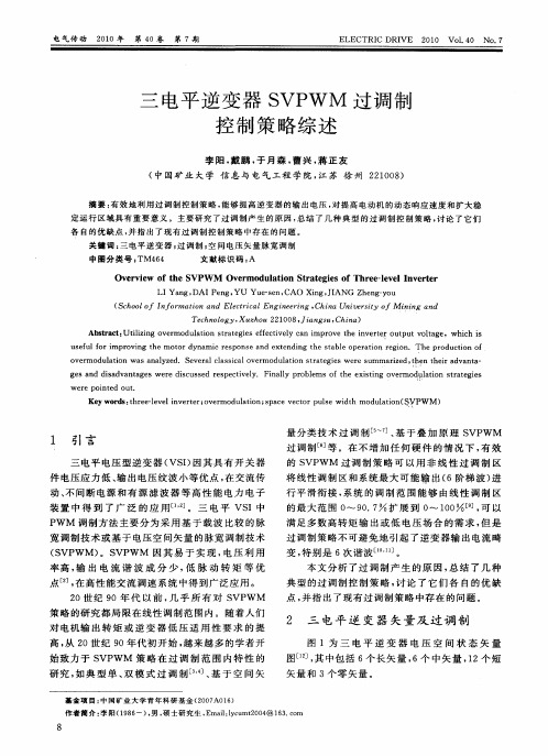
【摘要】有效地利用过调制控制策略,能够提高逆变器的输出电压,对提高电动机的动态响应速度和扩大稳定运行区域具有重要意义.主要研究了过调制产生的原因,总结了几种典型的过调制控制策略,讨论了它们各自的优缺点,并指出了现有过调制控制策略中存在的问题.
【总页数】5页(P8-11,17)
【作者】李阳;戴鹏;于月森;曹兴;蒋正友
【作者单位】中国矿业大学,信息与电气工程学院,江苏,徐州,221008;中国矿业大学,信息与电气工程学院,江苏,徐州,221008;中国矿业大学,信息与电气工程学院,江苏,徐州,221008;中国矿业大学,信息与电气工程学院,江苏,徐州,221008;中国矿业大学,信息与电气工程学院,江苏,徐州,221008
【正文语种】中文
【中图分类】TM464
【相关文献】
1.一种基于SVPWM的三电平逆变器中点电压平衡控制策略 [J], 周翔宇;张国荣;
2.60°坐标系下三电平逆变器SVPWM控制策略研究 [J], 陈晓鸥;许春雨;王枫明
3.三电平逆变器SVPWM过调制控制策略研究 [J], 谢奕尘
4.一种SVPWM过调制控制策略的分析与仿真 [J], 徐鲁辉;崔传辉
5.新颖的SVPWM过调制策略及其在三电平逆变器中的应用 [J], 金舜;钟彦儒;程为彬
因版权原因,仅展示原文概要,查看原文内容请购买。
三电平变换器SVPWM算法综述
三电平变换器SVPWM算法综述
于月森;姜小艳;符晓;夏帅;伍小杰
【期刊名称】《变频器世界》
【年(卷),期】2009(000)009
【摘要】本文介绍了三电平空间矢量脉宽调制(SVPWM)的基本原理,根据空间矢量调制的规律,重点介绍了五种三电平SVPWM算法,并对它们各自的特点进行了分析,包括古典算法;参考电压分解SVPWM算法;基于线电压坐标系的SVPWM算法;基于60°坐标系的SVPWM算法:基于120°坐标系的SVPWM算法。
最后针对上述五种算法,对三电平变换器中点电压的平衡控制进行了研究。
【总页数】6页(P35-40)
【作者】于月森;姜小艳;符晓;夏帅;伍小杰
【作者单位】中国矿业大学信电学院
【正文语种】中文
【中图分类】TM464
【相关文献】
1.三电平变换器SVPWM控制算法的研究 [J], 赵莉华;何雄;黄念慈
2.三电平变换器SVPWM控制算法的改进研究 [J], 何凤有;邓园;张贞飞;马志勋
3.基于简化SVPWM算法双三电平变换器研究 [J], 张晓;谭国俊;韩耀飞;王冬冬
4.基于FPGA的三电平变换器SVPWM调制方法的实现 [J], 刘海舰;丁佩剑;许恩泽;胡亮
5.三电平变换器SVPWM控制算法的优化 [J], 黄文美;张时明;孙英;李小鹏
因版权原因,仅展示原文概要,查看原文内容请购买。
基于三电平典型拓扑结构的SVPWM调制策略研究
基于三电平典型拓扑结构的SVPWM调制策略研究作者:王超然刘宇蝶来源:《无线互联科技》2024年第12期摘要:當前,我国的新能源技术面临发电量受外界因素影响较大、电能不能稳定输出等问题,大功率变换器的使用是解决此问题的关键,多电平逆变器能够满足大功率变换器的高压大功率化需求。
文章以T型三电平逆变器为研究对象,分析了其调制算法和中点电位平衡问题,并进行了仿真验证。
根据空间矢量脉宽调制(Space Vector Pulse Width Modulation,SVPWM)算法的原理,文章分析了中点电位不平衡对空间电压矢量作用的不良影响。
基于MATLAB/Simulink平台,文章搭建了仿真模型,仿真结果证明了三电平SVPWM算法对中点平衡控制策略的有效性。
所提方法能够弥补原有算法操作复杂的不足,对三电平乃至多电平逆变器的工程应用具有促进作用。
关键词:T型三电平逆变器;中点电位不平衡;SVPWM算法中图分类号:TM464;TP273文献标志码:A0 引言随着现代电力电子技术的迅速发展,适用于不同场合的多电平逆变器所具有的拓扑结构层出不穷,所对应的调制算法也千差万别。
T型三电平逆变器利用2个反向串联的功率开关管将直流母线侧的中点与输出端相连,实现中点箝位功能和零电流切换。
当中点电位发生变化时,T型三电平逆变器拓扑能够解决上、下桥臂的开关管功率损耗分布不均的问题,但存在中点电位动态不平衡的问题[1]。
空间矢量脉宽调制(Space Vector Pulse Width Modulation,SVPWM)的算法原理是将逆变器的输出状态转化为空间电压矢量,通过空间矢量的切换控制三电平变流器的开关管工作。
SVPWM算法所形成的系统模型简单,输出波形在大范围调制比内具有良好的性能、较小的输出谐波含量以及较高的电压利用率,易于实现抑制中点电位波动、减小谐波含量、减少开关频率等控制目标[2]。
因此,本文以三电平T型逆变器为研究对象,深入研究其SVPWM策略,弥补原有算法复杂、实际操作困难的缺陷;利用简易算法实现T型三电平逆变器的SVPWM;建立MATLAB/Simulink模型,分析了SVPWM算法对中点电位不平衡问题的抑制作用。
三电平逆变器的SVPWM控制与MATLAB仿真研究
三电平逆变器的SVPWM控制与MATLAB仿真研究三电平逆变器是一种常用的电力电子设备,具有输出波形质量高、效率高、功率密度大等优点。
SVPWM是一种常用于三电平逆变器的控制算法,可以实现对输出电压的精确调节。
本文将对SVPWM控制算法进行研究,并使用MATLAB进行仿真验证。
首先,介绍三电平逆变器的基本原理。
三电平逆变器由两个半桥逆变器和一个中间电压平衡电路组成。
其工作原理是通过控制两个半桥逆变器的开关状态,将输入直流电压转换为输出交流电压。
为了实现高质量的输出波形,需要对逆变器的开关状态进行精确控制。
SVPWM是一种常用的控制算法,通过控制逆变器的开关状态来实现对输出电压的精确控制。
SVPWM控制算法的基本原理是将三相交流信号转换为空间电压矢量,然后通过控制逆变器的开关状态来实现对输出电压的调节。
该算法采用三角波进行调制,根据三角波和参考信号之间的相位差确定逆变器的开关状态。
具体来说,根据参考信号和三角波的相位关系,可以将逆变器的开关状态分为六个不同的区间。
在每个区间中,逆变器的开关状态发生变化,从而实现对输出电压的调节。
为了验证SVPWM控制算法的性能,我们使用MATLAB进行仿真。
首先,我们需要建立逆变器的数学模型。
逆变器的数学模型可以通过电路方程和开关动态方程来建立。
然后,我们可以编写MATLAB代码来实现SVPWM控制算法。
在代码中,需要定义参考信号和三角波的频率和幅值,并根据相位差确定逆变器的开关状态。
最后,我们可以通过MATLAB的仿真工具来模拟逆变器的工作过程,并观察输出电压的波形和频谱。
通过对SVPWM控制算法的研究和MATLAB的仿真验证,可以得出以下结论。
首先,SVPWM控制算法可以实现对三电平逆变器输出电压的精确控制。
其次,通过调整参考信号和三角波的频率和幅值,可以实现不同频率和幅值的输出电压。
最后,MATLAB的仿真工具可以有效地验证SVPWM控制算法的性能,并对三电平逆变器的工作过程进行可视化分析。
二电平和三电平逆变器svpwm调制方法-概述说明以及解释
二电平和三电平逆变器svpwm调制方法-概述说明以及解释1.引言1.1 概述概述部分应该对二电平和三电平逆变器svpwm调制方法进行简要介绍,说明其在逆变器领域中的重要性和应用。
可以按照以下方式编写该部分的内容:概述逆变器是一种将直流电能转换为交流电能的装置,广泛应用于电力电子领域。
在逆变器的调制方法中,svpwm是一种常用且有效的调制技术。
根据逆变器的拓扑结构的不同,svpwm调制方法可以分为二电平和三电平两种。
二电平逆变器svpwm调制方法通过对逆变器开关管的控制,使输出波形接近正弦波,并最大化功率输出。
其调制原理是将高频三角波与标准正弦波进行比较,通过控制开关管的导通时间实现输出波形的控制。
二电平逆变器svpwm调制方法具有简单、可靠的特点,在许多应用中得到广泛使用。
相比之下,三电平逆变器svpwm调制方法引入了一个额外的中点电压,可以提供更高的输出电压质量。
其调制原理是将标准正弦波与两个输出电压等级的三角波进行比较,通过控制开关管的导通时间和电平,实现输出波形的更精确控制。
三电平逆变器svpwm调制方法适用于高功率应用和对输出电压质量要求较高的场景。
本文将重点探讨二电平和三电平逆变器svpwm调制方法的调制原理和实现方式,比较其优缺点,并对其应用前景进行展望。
二电平和三电平逆变器svpwm调制方法的研究对提高逆变器效率、降低谐波失真以及满足不同应用需求具有重要意义。
1.2 文章结构文章结构部分的内容应该包括对整篇文章的结构进行概括和简要说明。
可以按照以下方式编写:本文主要围绕着二电平逆变器SVPWM调制方法和三电平逆变器SVPWM调制方法展开讨论。
文章结构如下:第一部分为引言,包括概述、文章结构和目的。
在概述中,将会介绍逆变器的作用和重要性,以及SVPWM调制方法在逆变器中的应用背景。
文章结构将会简要列举本文的章节和主要内容。
目的部分将明确本文旨在比较二电平和三电平逆变器SVPWM调制方法的优劣以及探讨其应用前景。
- 1、下载文档前请自行甄别文档内容的完整性,平台不提供额外的编辑、内容补充、找答案等附加服务。
- 2、"仅部分预览"的文档,不可在线预览部分如存在完整性等问题,可反馈申请退款(可完整预览的文档不适用该条件!)。
- 3、如文档侵犯您的权益,请联系客服反馈,我们会尽快为您处理(人工客服工作时间:9:00-18:30)。
图 4 最小幅值误差过调制示意图 Fig.4 The minimum amplitude error overmodulation di agram
这种方法较 3 .1 节中的方法复杂 , 计算量大 , 电压 、电流波形失真程度也比最小相角误差过调 制大 。然而 , 它可以达到最大调制度为 1 , 此时输 出电压基波幅值为 2U dc/π, 充分利用了直流母线 电压[ 2 2] 。 3 .3 典型双模式过调制策略
关键词 :三电平逆变器 ;过调制 ;空间电压矢量脉宽调 制 中图分类号 :TM 464 文献标识码 :A
Overview of the SVPWM Overmodulation Strategies of Three -level Inverter
LI Yang , DAI Peng , Y U Yue -sen , CA O Xing , JIA N G Zheng -y ou (School of In f ormation and E lectrical Engineering , China University of Mining and
基金项目 :中国矿业大学青年科研基金(2007A 016) 作者简介 :李阳(1986 -), 男 , 硕士研究生 , Emai l :lycu mt 2004 @163 .com
8
李阳 , 等 :三电平逆变器 SV PWM 过调制控制策略综述
电气传动 2010 年 第 40 卷 第 7 期
图 1 三电平逆变器电压空间状态矢量图 Fig .1 Space vect or s tat e of t hree-lever inverter
只要参考电压矢量 Vref 的端点轨迹位于六边 形的内切圆内 , 根据伏秒平衡原则 , 就可以利用逆 变器的开关状态合成 Vref , 且 Vref 端点轨迹为六边 形内 切 圆 时 达 到 线 性 最 大 调 制 度 , 调 制 度 为 90.7 %(定义调制度 m = Vref /(2U dc/π)), 见图 2 。
图 5 典型双模式过调制 Fig .5 T he t ypi cal du al -m ode overmodulat ion
这种方法有较低的谐波畸变率(T H D), 但是 有相对复杂的控制算法 , 并且查表需要较大的内 存空间[ 21] , 因 此适合 于对谐 波指标 要求较 高的 应用 。 3 .4 典型单模式过调制策略
这种方法借鉴了 Joachim Holtz 的思想[ 3] , 将 9
电气传动 2010 年 第 40 卷 第 7 期
李阳 , 等 :三电平逆变器 S VP WM 过 调制控制策略综述
过调制区分为 2 部分 :0 .907 ≤m ≤0 .952(mode 1) 和 0 .952 ≤m ≤1 .0(mode 2)。在 mode 1 中 , 不修 改参考电压矢量角 θr , 而仅根据离线得到的 θr 与 调制度 m 的非线性关系对参考电压矢量的幅值 进行修改 ;在 mo de 2 中 , 根据离线计算得到的保 持角 θh 与调制度 m 的非线性关系 , 同时修改参考 电压矢量的幅值和相位 。 修正后的电压矢量端点 轨迹如图 5 中黑粗线所示 。Mode 2 中 , 当 θh =π/ 6 时 , 达到最大可能输出 , 此时调制度 m 为 1 , 修正 后的参考电压矢量仅为 6 个大矢量之一 , 输出相 电压为 6 阶梯波 。
这种方法 借鉴了 S .Bolog nani 的思想[ 4] , 通 过离线计算得到修改后的参考电压矢量的幅值与 m 的非线性关系 , 同时修改参考电压矢量的幅值 和相位 , 用一种控制模式即可实现从线性区到最 大调制的平滑过渡 。 修正后的电压矢量运行轨迹 如图 6 中黑粗线所示 。
图 6 典型单模式过调制 Fig .6 The t ypical singl e-mode overmodulati on
图 2 最大线性调制 Fig .2 T he maximu m li near modulati on
随着 Vref 幅值的进一步增大 , 其端点轨迹将 超出六边形 , SVPWM 出现过调制。在过调制 区 , 没有任何电压矢量 可在 Ts 时间 内准确合成 它 , 若仍按传统的调制方法计算 , 有些电压矢量作 用时间可能为负数 。 如不对参考电压矢量的幅值 进行限制 , 就会导致系统实际输出衰减 , 无法跟踪 指令电压 , 输出的电压 、电流波形发生畸变 , 对整 个系统的控制产生极为不利的影响 。
图 3 最小相角误差过调制示意图 Fig .3 The mini mum phase angle error overmodulation diagram
这种方法比较简单 , 易于实现 , 但其最大调制 度只能达到 95 .2 %, 即 V′的端点轨迹为 电压矢 量组 成 的 六 边 形 时 , 不 能 充 分 利 用 直 流 母 线 电压 。 3 .2 最小幅值误差过调制策略
电气传动 2010 年 第 40 卷 第 7 期
EL EC T RIC DRIV E 2010 Vo l.40 No .7
三电平逆变器 SVPW M 过调制 控制策略综述
李阳 , 戴鹏 , 于月森 , 曹兴 , 蒋正友 (中国矿业大学 信息与电气工程学院 , 江苏 徐州 221008)
摘要 :有效地利用过调制控制策略 , 能够提高逆变器的输出电压 , 对提高电动机的动态响应速度和扩大稳 定运行区域具有重要意义 。 主要研究了过调制产生的原因 , 总结了 几种典型 的过调制控 制策略 , 讨论了它 们 各自的优缺点 , 并指出了现有过调制控制策略中 存在的问题 。
在 3 .1 节的方 法中 , 当 Vref 的端 点位于六边 形之外时 , 将其投影到六边形的 ab 边上 , 形成以 点 c 为端点的新参考电压矢量 V′, 如图 4 所示 。 可以看出 , 在端点位于六边形边上的矢量中 , V′与 Vref 之间误差矢量的幅值最小 , 故称为最小幅值误 差过调制 。当 Vref > 2U dc/ π 时 , 如果 Vref 比较 靠近顶点 a , 则 Vref 的投影点将落在 ab 边之外 , 可 令 θ′=0 , 用 u7 代替 Vref ;同样 , 如果 Vref 比较靠近 顶点 b , 则 Vref 的投影点也将落在 ab 边之外 , 可令 θ′=π/ 3 , 用 u9 代替 Vref 。如果 Vref 足够大 , 随着 Vref 的旋转 , Vref 的端点在六边形的一个顶点停留 一段时间以后 , 直接跳到另一个端点 , 轨迹就是六 边形的 6 个顶点 。
量分类技术过调制[ 5 ~ 7] 、基于叠加原理 SV PWM 过调制[ 8] 等 。在不增加任何硬件的情况下 , 有效 的 SVPWM 过调制策略可以用非线性过调制区 将线性调制区和系统最大可能输出(6 阶梯波)进 行平滑衔接 , 系统的调制范围能够由线性调制区 的最大范围 0 ~ 90 .7 %扩展到 0 ~ 100 %[ 9] , 可以 满足多数高转矩输出或低电压场合的需求 , 但是 过调制策略不可避免地引起了逆变器输出电流畸 变 , 特别是 6 次谐波[ 10 , 11] 。
1 引言
三电平 电压 型逆 变 器(V S I)因其 具 有 开关 器 件电压应力低 、输出电压纹波小等优点 , 在交流传 动 、不间断电源和有源滤波器等高性能电力电子 装置中得 到了 广泛 的应 用[ 1 , 2] 。 三 电平 V SI 中 PWM 调制方法主要分为采用基于载波比较的脉 宽调制技术或基于电压空间矢量的脉宽调制技术 (SVPWM)。 SV PWM 因其易于实现 , 电压利用 率高 , 输 出 电 流谐 波 成 分 少 , 低 脉 动 转 矩等 优 点[ 2] , 在高性能交流调速系统中得到广泛应用 。
3 过调制控制策略
针对过调制运行时出现的问题 , 国内外很多 学者进行了研究 , 至今已取得了多项成果[ 13 ~ 35] , 下面介绍几种典型的过调制策略 。 3 .1 最小相角误差过调制策略
其基本原理是 :对 Vref 的端点轨 迹超出六边 形的部分 , 保持 Vref 的 相位角不变 , 将 Vref 的端点 强制固定在六边形上形成新的矢量 V′, 同时未超 出六边形的部分仍保留 为圆形 。 因此 , 最后 Vref 的端点轨迹为 ab 段圆弧 、bc 段直线 、cd 段圆弧 , 如图 3 所示 。 因为 V′与 Vref 有相同的相角 , 故这 种方法具有最小相角误差的优点 。