New Possibilities for Controlling the Morphology of Core-Shell Latex Particles During Emulsion
PreparationofASA(acrylonitrile-styrene-acrylate)structurallatexes
Preparation of ASA (acrylonitrile-styrene-acrylate)structural latexes via seeded emulsion polymerizationShima Tolue a ,Mohammad Reza Moghbeli a,*,Seyed Mehdi Ghafelebashi ba School of Chemical Engineering,Iran University of Science and Technology (IUST),Maleklo St.,Khavar St.Farjam St.Narmak,P.O.Box 16844-13114,Tehran,Iran bPetrochemical Research &Technology Company (NPC-RT),P.O.Box 14358,Tehran,Irana r t i c l e i n f o Article history:Received 26August 2008Received in revised form 3December 2008Accepted 5December 2008Available online 24December 2008Keywords:Acrylonitrile-styrene-acrylate core–shell latexNon-ionic surfactantMonomer addition modeSeeded emulsion polymerizationa b s t r a c tAcrylonitrile-styrene-acrylate (ASA)structural latexes were synthesized in a two-stage seeded emulsion polymerization.In the first-stage,partially cross-linked poly (n -butyl acrylate)(P n BA)and poly (n -butyl acrylate-stat-2-ethyl hexyl acrylate)P (n BA-stat-2EHA)(75/25by wt)rubber cores were synthesized,and then in the second-stage,a hard poly (styrene-stat-acrylonitrile)(SAN)(70/30by wt)shell was grafted on to the rubber seeds.The effects of surfactant type and second-stage monomer addition mode have been investigated on the final morphology of two-stage emulsion particles.The results indicated that an application of anionic surfactant,that is,sodium dodecyl sulfonate (SDS),along with sodium persulfate (KPS)initiator for both stages,and with first-stage tert -butyl hydro-peroxide (t -BHP)and second-stage KPS initiators led to a hemisphere particle morphology.On the other hand,raspberry and core–shell structures were observed for the structural latexes,which were prepared using a non-ionic surfactant,that is,nonylphenol ethoxylat-ed polyethylene glycol (Igepal CO-850),accompanying KPS initiator for both stages.It is clear,however,that the relative surface hydrophilicity of the core phase,altered by the sur-factant type considerably affected the type of morphology formed.For obtained structural latexes,the gradual addition of the second-stage monomers to the core latexes resulted in a fairly real core–shell structure with a higher shell thickness.On the contrary,a raspberry structure in which the rubber phase was enlarged by the second-stage polymer microdo-mains was observed for the second-stage monomer addition batch.In fact,the shell semi-batch polymerization conditions lower the shell plasticizing effect,and increase the kinetic barrier to prevent from further second-stage monomer diffusion and microdomain forma-tion within the rubbery phase.Ó2008Elsevier Ltd.All rights reserved.1.IntroductionPreparation of structured latex particles with predeter-mined complex morphologies and a variety of functions has attracted the interest of scientists for many years [1,2].These polymer materials are widely used in indus-trial applications,for example,coating,adhesives,paints,and rubber modification of some brittle thermoplastic polymers and thermoset resins to improve their inherentphysical and mechanical properties [3–8].Core–shell im-pact modifiers as typical structured latex particles have been prepared via a two-stage emulsion polymerization process [9–15].The rubber cores with low glass-transition temperatures (T g )are synthesized in the first-stage emul-sion polymerization.In the second-stage,that is,seeded emulsion polymerization,a glass thermoplastic polymer is grafted onto the rubber seeds by addition across the residual double bonds or hydrogen abstraction from the rubber chains,to give radicals which add monomer units to form a grafted branch.In most cases,the resulting particle morphology in the seeded emulation polymerization cannot result in a core–0014-3057/$-see front matter Ó2008Elsevier Ltd.All rights reserved.doi:10.1016/j.eurpolymj.2008.12.014*Corresponding author.Fax:+912177240495.E-mail address:mr_moghbeli@iust.ac.ir (M.R.Moghbeli).European Polymer Journal 45(2009)714–720Contents lists available at ScienceDirectEuropean Polymer Journaljournal homepage:www.elsevie r.c o m /l o c a t e /e u r o p o l jshell structure with completely separated core and shell phases[16,17].Varying some polymerization parameters, such as emulsifier and initiator types,the amount of cross-linker,core-to-shell phase ratio,monomer composi-tion,and monomer addition mode at different polymeriza-tion stages provide various composite particle morphologies[17–25].In many cases,the observed particle morphology that deviates from the ideal core–shell struc-ture including morphologies are described simply as hemi-spherical,raspberry,mushroom,and confetti in the literatures[16,17].In fact,the diversity in composite parti-cle morphologies can be attributed to the phenomenologi-cal thermodynamic/kinetic behaviors which control the phase distribution within particles in the seeded emulsion polymerization[17,26].Commercialized core–shell structured latex particles as impact modifiers are composed of traditional grafted rub-ber–thermoplastic materials,such as methacrylte-butadi-ene-styrene(MBS),all-acrylics impact modifier(AIM), and acrylonitrile-butadiene-styrene(ABS).Commercial acrylonitrile-styrene-acrylate(ASA)core–shell latexes, with obvious similarities to ABS latexes,have also been developed for the toughening of rigid SAN copolymers by a few industrial manufacturers[27].Although the graft shell in both ABS and ASA modifiers is similar,the hydro-phobic poly(butadiene)(PB)rubber core within the ABS particles is substituted by the less hydrophobic P n BA rub-ber core in the ASA particles.Thus,the difference in the interfacial tension of various rubber cores against water, and in their compatibilities to the shell polymer units may lead to some significant complexities in their manu-facturing process.Although more research investigations have been car-ried out in the preparation of ABS latexes,less attention has been paid to the preparation of ASA latexes[27].In the present research work,the effects of surfactant type and second-stage monomer addition mode on thefinal morphology of the ASA emulsion particles have been investigated.2.Experiments2.1.MaterialsAll reagents were prepared from Merck Co.,unless otherwise stated.Styrene(St),n-Butyl acrylate(n BA), and acrylonitrile(AN)were distillated under vacuum to remove their inhibitors.Allyl methacrylate(ALMA)from Aldrich and tertiary dodecyl mercaptan(TDM)from Fluka were purchased as cross-linking agent and chain-transfer agent,respectively.Sodium dodecyl sulfonate(SDS)as an-ionic surfactant and nonylphenol ethoxylated polyethyl-ene glycol(Igepal CO-850)as non-ionic surfactant from Rhodia,potassium persulfate(KPS)and water soluble tert-butyl hydroperoxide(t-BHP)both as initiators were used directly without any further purification.Tetrahy-drofuran(THF)and toluene,both analytical grades,were purchased for solvent extraction experiments.Distillated deionized water(DDI)was prepared in the laboratory of the author.2.2.Core and core–shell synthesisThe ASA core–shell latexes were synthesized via a two-stage seeded emulsion polymerization.Acrylate rubber core and core–shell polymers were prepared in a150-ml three-neck glass reactor equipped with a reflux,inlet nitrogen, and a magnetic stirrer.The reactor was held in a bath with thermostatic control.Firstly,P n BA and P(n BA-stat-2EHA) core latexes were synthesized at80°C and250rpm for 3.5h according to the emulsion recipes listed in Table1.Var-ious types of aforementioned initiators and emulsifiers were utilized to make the rubber cores with different surface polarities.In the second-stage polymerization,the St/AN (70/30)monomer mixture was added to form the shell layer over the rubber cores at80°C and250rpm for3.5h in batch and semi-batch seeded emulsion polymerization processes (Table2).Synthesized ASA emulsion particles were desig-nated with a common name CS,a recipe number correspond-ing to a core recipe listed in Table1,and an abbreviation B or SB which is a representative of the shell batch(B)or semi-batch(SB)emulsion polymerization process.2.3.Characterization2.3.1.Gel content of the seed latexThe gel content of rubber seed particles was measured via solvent extraction method.Three samples of dried P n BA and P(n BA-stat-2EHA)film,0.25g each were added to25ml THF,and stirred at300rpm and room tempera-ture for48h.Then samples were centrifuged at5000rpm for1h.The sediment gel phase was separated from the sol phase and dried in a vacuum oven at50°C.The gel frac-tion was determined gravimetrically,based on the total weight of the sample.2.3.2.Grafting degreeIn order to determine the grafting degree,the compos-ite latexes were freeze-dried to afine powder,and placed in a vacuum oven at40°C for3h to remove the trace amount of water.Then,three samples of powder,1g each, were dispersed in25ml toluene and were stirred at room temperature and300rpm for8h.The dispersions were centrifuged at5000rpm for2h at4°C.The gel phase at the bottom of the cell was separated from supernatant phase,and both fractions were dried to remove solvents under vacuum at40°C for24h.The grafting degree,the weight ratio of grafted SAN to rubber seed particles,G d, was measured gravimetrically.Table1Recipes for the preparation of acrylate seed latexes.Ingredients a C1C2C3C4BA24242418 2EHA0006 DDI72727272 KPS0.06–0.060.06 t-BHP–0.06––ALMA0.090.090.090.09 SDS0.120.12––Igepal CO-850––0.330.33a Quantities are in weight parts.S.Tolue et al./European Polymer Journal45(2009)714–7207152.3.3.Particle size and size distributionThe size and size distribution of the latex particles were measured via dynamic laser light scattering(DLLS)with a wavelength of632.8nm and laser-source light He and Ne gas.Light-scattering measurements were performed using a Sematech SEM-633stepper-motor-driven goniometer.The particle size and polydispersity index(PDI),the ratio of the weight-to-number average diameter,D w/D n, which is a representative of latex particle size distribution, were also determined by transmission electron micros-copy,TEM,technique based on300particles for each sample[28].2.3.4.Glass-transition temperature(T g)The T g values of the graft copolymers were determined with a differential scanning calorimeter,Mettler Toledo DSC822system.The temperature scanning range was À150to150°C at a heating rate ofÀ10°C/min under a nitrogen atmosphere.2.3.5.Contact-angle measurementContact angle of a water drop on a dried latexfilm was used to estimate the hydrophilicity of the core and shell latex polymers prepared by using various surfactants.The dried PBA latexfilm and the compression-molded SAN latex powder were annealed at40°C and120°C under vacuum for2h,respectively,before measurement.2.3.6.Morphology of latex particlesTransmission Electron Microscopy,TEM,Zeiss CEM 902A,was used to observe the morphology of structural la-tex particles.The latexes were further diluted with distillat-ed water,and then diluted droplets was transferred onto the copper grids,mesh200,and dried in open air.Then the sam-ples were stained by osmium tetroxide vapor(OsO4)and phosphotungstic acid(PTA)solution1%before microscopy, in order to distinguish the core and shell regions.3.Results and discussion3.1.ASA latex synthesisThe ASA latex particles with a soft P n BA and P(n BA-stat-2EHA)cores,and a hard SAN shell were synthesized via a two-stage emulsion polymerization.Two different anionic and non-ionic surfactants,and anionic and non-ionicfirst-stage initiators were used to synthesis the ASA latexes (Table2).In all cases,the second-stage initiator was the anionic type,and the relative amount of the shell phase to rubber core was selected to50/50(wt/wt).For the ASA latexes prepared using the non-ionic surfactant,the sec-ond-stage monomer mixture was added at the beginning of polymerization in a preswelling batch process condition or during the polymerization reaction in a semi-batch pro-cess with a constant feeding rate(Table2).3.2.ASA particle propertiesThe characteristics of the prepared rubber cores and ASA latex particles are indicated in Table3.As shown,changing the emulsifier type from anionic to non-ionic one in the first-stage polymerization caused the rubber particle size to increase considerably,while the gel content was approx-imately constant,except for the rubber particles synthe-sized using t-BHPfirst-stage initiator(Table3).Thus,the initiator type seems to play an important role in determin-ing the gel content of the acrylate cores for a given cross-linking agent level.In fact,the success of the various initia-tors in the preparation of gel particles and graft copolymers depends critically on the kinetics and mechanism of radical production,initiator efficiency,and the relative stability of the various radical generating functions[29].On the other hand,applying a special kind of cross-link-ing/compatibilizing agent in thefirst-stage emulsion poly-merization,that is,allyl methacrylate(ALMA),resulted in preparing structural core–shell particles with a rather high grafting degree,even for the high gel-containing acrylate rubber particles.Nevertheless,the grafting degree of the composite particles prepared using the non-ionic surfac-tant was higher than that of the particles synthesized using the anionic surfactant(Table3).This is due to the higher grafting density of the SAN copolymer chains tethered to the rubber chains and more interfacial area exists between two incompatible phases.Unexpectedly,the grafting de-gree of the ASA composite particles prepared in the shell semi-batch polymerization process was found to be lower than that of the particles synthesized in the shell batch polymerization process.This behavior can be attributed to the resulting composite particle morphology formed in the batch polymerization process,compared to the mor-phology resulted in the shell semi-batch polymerization.Two glass-transition temperatures were observed for all the ASA structured latex particles.The lower glass-transi-tion temperature corresponds with the T g of the rubbery core and the upper temperature belongs to the SAN shell polymer.The glass-transition temperatures of the compos-ite particles are summarized in Table3.As one can expect, the ASA composite particles based on P(n BA-stat-2EHA) rubber core showed a lower T g in comparison with those that were based on the P n BA rubber core.3.3.ASA particle morphology3.3.1.Effect of surfactant typeAs well-known,the morphology of composite latex par-ticles is crucial for achieving the desired properties of theseTable2Recipes for the preparation of ASA latexes.Ingredients a CS1-B b CS2-B CS3-B/CS3-SB c CS4-B/CS4-SBSeed latex50505050St8.608.608.608.60AN 3.72 3.72 3.72 3.72KPS0.030.030.030.03SDS0.0050.005––Igepal CO-850––0.010.01NaHCO30.10.10.10.1TDM0.0120.0120.0120.012a Quantities are in weight parts.b The second-stage monomer mixture was added at the beginning ofthe polymerization,batch operation(B).c The monomer mixture feeding rate in the semi-batch(SB)second-stage polymerization was0.2ml/min.716S.Tolue et al./European Polymer Journal45(2009)714–720structural polymer materials,which depend on many parameters in the two-stage emulsion polymerization. The particle morphology of the ASA latexes was studied by means of transmission electron microscopy(TEM).This conventional characterization method gives clearer infor-mation on the particle morphology,but contains some dif-ficulties in sample preparation method especially for the ASA and AIM core–shell emulsion particles which have chemical similarities amongst their intrinsic constituents. Fig.1shows the morphology of the ASA particles consisted of a soft P n BA or P(n BA-stat-2EHA)core which is partially or completely engulfed by a hard SAN shell.As indicated in the TEM micrographs,the dark and bright regions of the composite particles represent the soft rubber and hard shell polymer phases,respectively.For the ASA latexes, the existence of residual and entrapped double bonds of the ALMA comonomer within the rubber core microgels caused OsO4to stain the acrylic core phase preferentially allowing one to distinguish it from the SAN shell.For the ASA latexes prepared using anionic surfactant,a complete phase-separated-type particle with hemisphere and cham-pignon morphologies was observed(Fig.1a and b).On the contrary,using P n BA or P(n BA-stat-2EHA)rubber seeds prepared with the non-ionic surfactant in both shell batch and semi-batch polymerization resulted in ASA core–shell-type morphologies(Fig.1c–f).These different composite morphologies that appeared to be arising from using dif-ferent surfactant types can be ascribed to the thermody-namic/kinetic control limitations that determine thefinal morphology based on getting the minimum possible Gibbs free energy of the system.From a thermodynamic point of view,it was shown that only small differences in Gibbs free energy arise from changing the interfacial tensions are re-quired to vary composite particle morphology from core–shell to partially engulfed structure[17].In fact,one of the most direct approaches to change the composite parti-cle morphology is to use various surfactants and initiators to modify the surface character of the products offirst and subsequent stage polymerization[20].As shown in Table4,the PBA latex particles prepared using both the ionic initiator and surfactant have a higher contact angle and surface hydrophilicity than the shell polymer prepared with the same ionic initiator and surfac-tant ones.As well-known,a system with a hydrophilic core and a hydrophobic shell would be inherently difficult to achieve because of the thermodynamic constrains[30]. Nevertheless,using the non-ionic surfactant in such a com-plicated system varying the core surface character resulted in ASA composite emulsion particles with core–shell morphology.3.3.2.Effect of second-stage monomer addition modeInterestingly,the core–shell-type morphologies ob-served for the ASA latexes using non-ionic surfactant were different,dependent upon the type of monomer addition mode applied in the second-stage polymerization.Obvi-ously,a fairly real core–shell structure with a bright thick shell rings around the rubber seeds was observed for the ASA latex particles,which were synthesized under the starved monomer feed in the second-stage polymerization (Fig.1d and f).In contrast,particle morphology similar to like that is between the raspberry and core–shell struc-tures was observed for the shell batch polymerization con-ditions(Fig.1c and e).This inhomogeneous raspberry-like morphology with a non-uniform size of SAN microbeads on the rubber core surface could suggest an initiation of the second-stage polymerization by a homogenous nucle-ation mechanism as previously discussed in other seeded emulsion polymerization systems[31,32].It was shown that the primary particles collide with thefirst-stage core, adhere,and grow and then coagulate to form the shell[32]. On the other hand,swelling the partially cross-linked rub-ber cores by all the shell monomer units at the beginning of the reaction in the batch process cannot provide the de-sired condition in which the second-stage polymer was completely placed on the outside of thefinal particles.In this case,the probable formation of second-stage polymer microdomains within the core region of the core–shell par-ticles seems to enlarge intensively the rubber phase as compared with the particles prepared in the shell semi-batch polymerization process.Thus,thefinal latex parti-cles may display an internal phase-separated granular structure[33].Inversely,for the structured particles pre-pared under shell semi-batch or starved-feed polymeriza-tion condition,a core–shell structure with a smaller rubber phase and higher shell thickness was observed (Fig.1d and f).In the shell semi-batch polymerization,a gradual monomer addition prevents from further plastisiz-ing effect of the second-stage monomers in thefirst-stage polymer,the conditions which cause the particle morphol-Table3The characteristics of the synthesized core and core–shell particles.Code D a(nm)D n b(nm)D w b(nm)PDI b Gel(%)G d(%)T g c(°C)Core ShellCS1-B177.1177.0198.1 1.1276.836.7––CS2-B149.7149.0162.5 1.0941.434.2––CS3-B475.6522.0564.4 1.0872.666.4À46.5106.3 CS3-SB446.2529.0653.6 1.2372.657.3À47.6107.1 CS4-B591.0502.4516.1 1.0368.554.7À51.1103.7 CS4-SB584.7519.5526.8 1.0168.545.9À50.9104.2a The mean diameter of the ASA latex particles is measured by means of DLLS apparatus.b The weight and number-average particles diameters,Dwand D n,respectively,and PDI were determined by TEM.c The glass-transition temperatures(Tg)of the P n BA and P(n BA-stat-2EHA)rubber seeds measured by DSC experiment wereÀ49.7andÀ58.7°C, respectively.S.Tolue et al./European Polymer Journal45(2009)714–720717ogy to deviate from the ideal core–shell structure.It can be assumed that the formation and growth of an initial rigid shell layer formed around the soft rubber phase raised a ki-netic barrier to prevent forming further monomer diffusion into the rubber seeds.Fig.2shows the DSC curves of a rubber core,a SAN copolymer with 30wt%AN,and an ASA graft rubber mate-rial which was synthesized via shell semi-batch polymeri-zation for comparison purposes.An enhancement in the T g of the rubber phase from À49.7°C for the P n BA seeds to À46.6°C for the P n BA rubber phase of the ASA latex parti-cles was observed.This temperature enhancement can be attributed to the existence of second-stage polymer micro-domains within the rubber phase of the ASAcompositeFig.1.TEM micrographs of ASA structured latex particles prepared using different surfactants,first-stage initiators,and second-stage monomer addition modes:(a)CS1-B,(b)CS2-B,(c)CS3-B,(d)CS3-SB,(e)CS4-B,and (f)CS4-SB.(The structured latex particles were positively stained by OsO 4vapor and magnification is 30,000Â.)718S.Tolue et al./European Polymer Journal 45(2009)714–720particles.In fact,to some extent,the occluded rigid poly-mer units within the swollen rubbery phase seem to influ-ence slightly the mobility and T g of the soft rubber chains.Nevertheless,the DSC results indicate two T g for all the ASA latex samples prepared by both shell batch and semi-batch polymerization processes,corresponding to the acrylate core and shell polymers,respectively (Fig.3).4.ConclusionAcrylonitrile-styrene-acrylate (ASA)latexes were pre-pared via seeded emulsion polymerization to overcoat an acrylate P n BA and P(n BA-stat-2EHA)seed polymers with a glassy SAN copolymer shell.For the ASA latexes,using anionic surfactant in the two-stage emulsion polymeriza-tion resulted in a complete phase-separated-type particle with a hemisphere or champignon morphologies.Decreas-ing the surface hydrophilicity of the rubber seeds using non-ionic surfactant caused a raspberry and core–shell particle structures dependent upon the mode of monomer addition was observed.When the St/AN shell monomer mixture was added gradually to the rubber seed latex,semi-batch or starved-feed condition,a real ASA core–shell particles consisting of completely separated rubber core and shell phases was obtained (Fig.4).On the contrary,the results showed that a raspberry structure with sec-ond-stage polymer inclusion and thicker core and shell interphase layer was observed for the ASA composite la-texes which were prepared via shell batch emulation polymerization.AcknowledgmentsThe authors gratefully thank the Petrochemical Re-search and Technology Company of Iran for partial finan-cial support of this work.References[1]Paul DR,Bucknall CB.Polymer blends.Performance,vol. 2.NewYork:A Wiley-interscience Publication;1999.[2]Kim H,Keskkula H,Paul DR.Polymer 1990;31:869.[3]El-Asser MS,Hu R,Dimonie WL,Sperling LH.Colloids Surf A:Physiochem Eng Aspects 1999;153:241.[4]Huang Y-J,Wu J-H,Liang J-G,Hsu M-W,Ma J-K.J Appl Polym Sci2008;107:939.[5]Lin KF,Shieh YD.J Appl Polym Sci 1998;70:2313.[6]Wu G,Zhao J,Shi H,Zhang H.Eur Polym J 2004;40:2451.[7]Kim H,Keskkula H,Paul DR.Polymer 1991;32:1447.[8]Bagheri R,Pearson RA.J Mater Sci 1996;31:3945.[9]Dimonie V,El-Asser MS,Klein A,Vanderhoff JW.J Polym Sci:PolymChem Ed 1984;22:2197.[10]Lee J-S,Chang F-C.Polym Eng Sci 2004;44:1885.[11]Merkel MP,Dimonie VL,El-Asser MS,Vanderhoff JW.J Polym Sci:Part B:Polym Chem 1987;25:1219.Table 4Measured contact angles on various latex films.Sample Initiator type Surfactant type Contact angle (°)C1Ionic Ionic102.2C3Ionic Non-ionic 89.2SAN a Ionic Ionic97.0SAN aIonicNon-ionic93.7aThe SAN latexes were synthesized with the same recipes and poly-merization conditions which were applied to the core latexes.CS3-B SAN-2.5-2-1.5-1CS3-B CS3-SB CS4-B CS4-SBS.Tolue et al./European Polymer Journal 45(2009)714–720719[12]Hu R,Dimonie VL,El-Asser MS.J Appl Polym Sci1997;64:1123.[13]Moghbeli MR,Mohammadi N,Bagheri R.J Appl Polym Sci2007;105:1412.[14]Lin K-F,Shieh Y-D.J Appl Polym Sci1998;70:2313.[15]Sue HJ.Polym Eng Sci1991;31:270.[16]Landfester K,Spiess HW.Acta Polym1998;49:451.[17]Kirsch S,Pfau A,Stubbs J,Sundberg D.Colloids Surf A:PhysiochemEng Aspects2001;183:725.[18]Cho I,Lee KW.J Appl Polym Sci1985;30:1903.[19]Lee C-F.J Polym Sci Part A:Polym Chem2005;43:2224.[20]Rudin A.Macromol Symp1995;92:35.[21]Herrera V,Pirri R,Asua JM,Leiza JR.J Polym Sci Part A:Polym Chem2007;45:2484.[22]Min TI,Klein A,El-Aasser MS,Vanderhoff JW.J Polym Sci:PolymChem Ed1983;21:2845.[23]Jonsson JE,Karlsson OJ,Hassander H,Tornell B.Macromolecules1994;27:1932.[24]Jonsson JE,Karlsson OJ,Hassander H,Tornell B.Macromolecules2001;34:1512.[25]Stubbs JM,Sundberg DC.J Appl Polym Sci2004;91:1538.[26]Stubbs J,Karlsson O,Jonsson JE,Sundberg E.Durant Colloids Surf A:Physiochem Eng Aspects1999;153:255.[27]Scheirs J,Priddy DB.Modern styrenic polymers:polystyrene andstyrenic copolymers.John Wiley&Sons Ltd.;2003.[28]Juang MS,Krieger IM.J Polym Sci:Polym Chem Ed1976;14:2089.[29]Moad G,Solomon DH.The chemistry of free-radical polymerization.2nd ed.The Netherlands:Elsevier Ltd.;2006.[30]Lee S,Rudin A.J Polym Sci:Part A:Polym Chem1992;30:865.[31]Mrkic J,Saunders BR.J Colloid Interface Sci2000;222:75–82.[32]Sommer F,Duc TM,Pirri R,Meunier G,Quet ngmuir1995;11:440–8.[33]Zukoski CF,Saville DA.J Colloid Interface Sci1985;104:583–6.720S.Tolue et al./European Polymer Journal45(2009)714–720。
核/壳乳液聚合中影响乳胶粒形态的因素
tr oy rc e lin p ril o f u ain i i u s d e t t a y An l l t e a t o on e u h a et u e p lme / muso a t e c n g r t s d s s e mp k i / . d nO' h u h r p itd o t te lts c i o c ac]  ̄, t n s o o e—s elp lme iai n r s a c r d fc r e h l oy r t e e r h. z o
起 人 们 的兴 趣 _ 。 4
的最 大 差 异 在 于 : / 乳 液 聚合 得 到 的 乳 液 抗 粘 核 壳
不 同 的两 种 或 多 种单 体 分 子 在 一 定 条 件 下 按 阶 段 聚 合 即种 子 聚 合 或 多 阶 段 聚 合 , 乳 液 颗 粒 内 部 的 内 使
中 已经 获 得 了 广 泛 的 应 用 _3。 核 / 乳 液 聚 合 提 2 . J 壳
出 了“ 子设 计 ” 新 概 念 , 在 不 改 变 乳 液 单 体 组 粒 的 即
c : a t n me h n s , t o s tc n q e fc r t Re c o c a im meh d ,e h i u s o o e—s e muso n r p r t n a d p f mu e f i h l e l n a d p e a ai n e o mc s o l i o
K e wor y ds: e— S l p lmerz to Co e— S elsr cur muso Pa tce c n g r in Cor hel oy iai n; r h l tu t e e lin; ri l o f u at i o
多形貌纳米银粒子的制备工艺研究

多形貌纳米银粒子的制备工艺研究刘锦涛;马运柱;刘文胜;唐思危;黄宇峰【摘要】随着电子元器件向微型化、精密化和柔性化等方向发展,金属导电填料纳米化成为电子封装用导电银浆发展的必然趋势.其中,多形貌纳米银粒子的制备成为该领域的研究热点.采用液相还原法,通过多种表面活性剂的添加调控纳米银晶粒的生长过程,制备出球状、片状、立方状等多种形貌的银纳米粒子,并揭示了它们的生长机理.结果表明,随着聚乙烯吡咯烷酮(PVP)浓度的增加,纳米银颗粒的分散性得到逐步优化,当PVP浓度为2 mmol/L时,制备出平均粒径为20 nm左右且分散性良好的球状银纳米粒子;柠檬酸钠和双氧水的添加能够诱导纳米银颗粒向片状结构转变,当柠檬酸钠浓度为20 mmol/L,双氧水浓度为25 mmol/L左右时,有大量片状银纳米粒子的形成;氯化钠(NaCl)能够诱导纳米银颗粒向立方体结构转变,当NaCl浓度为20 mmol/L时能够得到形状规则的立方银纳米粒子.【期刊名称】《功能材料》【年(卷),期】2018(049)007【总页数】7页(P7197-7203)【关键词】多形貌;纳米银粒子;液相还原法;调控;生长机理【作者】刘锦涛;马运柱;刘文胜;唐思危;黄宇峰【作者单位】中南大学粉末冶金研究院,长沙 410083;中南大学粉末冶金研究院,长沙 410083;中南大学粉末冶金研究院,长沙 410083;中南大学粉末冶金研究院,长沙 410083;中南大学粉末冶金研究院,长沙 410083【正文语种】中文【中图分类】TG4920 引言随着电子工业器件朝向高功率、多功能、小尺寸和低能耗的发展趋势,能否研究出在低温条件下固化的低电阻率的导电银浆已经成为电子工业发展的关键因素之一。
然而,这种导电银浆对作为导电相的银粉的形貌、粒径等的要求非常严格,所以以纳米银粒子作导电相的纳米导电银浆受到研究者们的广泛关注[1-3]。
研究表明,纳米银颗粒固含量为5%~40%的银浆可在低温条件下形成高导电性的电子线路[4],同时,不同形貌纳米银颗粒以一定比例混合作为导电相可在一定程度上降低浆料的接触电阻,完善导电网络,提高电导率[5]。
基于分子动力学的氧化石墨烯对PVA纤维-CSH界面影响机理研究
第42卷第11期2023年11月硅㊀酸㊀盐㊀通㊀报BULLETIN OF THE CHINESE CERAMIC SOCIETY Vol.42㊀No.11November,2023基于分子动力学的氧化石墨烯对PVA 纤维-CSH界面影响机理研究臧㊀芸,王㊀攀,王慕涵,王鑫鹏,侯东帅,赵铁军(青岛理工大学土木工程学院,青岛㊀266520)摘要:纤维增强混凝土的宏观力学性能与纤维/基体的界面结合密切相关㊂本文通过分子动力学模拟,研究氧化石墨烯(GO)对聚乙烯醇纤维(PVA)/基体界面结合的影响㊂结果表明,当GO 与PVA 纤维以共价键连接时,PVA 纤维从混凝土中被拉出所需的拉力最大,GO 的存在能提升纤维与基体的界面黏结性能㊂混凝土基体与GO 主要以钙氧键和氢键连接,其中钙氧键数量多且化学键强度高㊂但GO 与PVA 纤维物理连接时,GO 与PVA 纤维仅依靠强度较弱的氢键连接,对界面的黏结性能带来负面作用㊂此外,GO 受到更多离子键和氢键的束缚,原子平移运动减少,与基体的界面黏结性能提高㊂关键词:氧化石墨烯;PVA 纤维;混凝土;界面;分子动力学中图分类号:TU528㊀㊀文献标志码:A ㊀㊀文章编号:1001-1625(2023)11-3799-08Influence Mechanism of Graphite Oxide on PVA Fiber-CSH Interface Based on Molecular DynamicsZANG Yun ,WANG Pan ,WANG Muhan ,WANG Xinpeng ,HOU Dongshuai ,ZHAO Tiejun (Department of Civil Engineering,Qingdao University of Technology,Qingdao 266520,China)Abstract :The macroscopic mechanical properties of fiber reinforced concrete are closely related to the interfacial bonding of fiber /matrix.In this paper,the effect of graphene oxide (GO)on the interfacial bonding of polyvinyl alcohol fiber (PVA)/matrix was studied by molecular dynamics simulation.The results show that when GO and PVA fiber are connected by covalent bond,the tensile force required for PVA fiber to be pulled out from concrete is the largest,and the presence of GO can improve the interfacial bonding performance between fiber and matrix.The concrete matrix and GO are mainly connected by calcium-oxygen bonds and hydrogen bonds,in which the number of calcium-oxygen bonds is large and the strength of chemical bonds is high.However,when GO and PVA fiber are physically connected,GO and PVA fiber are only connected by weak hydrogen bonds,which has a negative effect on the bonding performance of interface.In addition,GO is bound by more ionic bonds and hydrogen bonds,the atomic translational motion is reduced,and the interfacial bonding performance with matrix is improved.Key words :graphene oxide;PVA fiber;concrete;interface;molecular dynamics 收稿日期:2023-06-01;修订日期:2023-08-12基金项目:国家自然科学基金(U2006224,51978352,51908308)作者简介:臧㊀芸(1986 ),女,博士研究生㊂主要从事土木工程材料方面的研究㊂E-mail:zangyun001@通信作者:侯东帅,博士,教授㊂E-mail:dshou@ 0㊀引㊀言水泥基材料是应用最广泛的建筑材料之一,然而它存在脆性大㊁韧性差㊁易发生突然破坏和耐久性差等缺点㊂添加纤维是提高水泥基材料抗拉强度和韧性的常用方法[1],纤维的主要作用是在断裂区起到桥接作用㊂聚乙烯醇(polyvinyl alcohol,PVA)纤维因其优异的耐碱性能㊁高强度和高弹性而备受关注,已被广泛应用于应变硬化水泥基材料(strain hardening cementitious composites)的制造[2]㊂然而,PVA 纤维尚未被证明可以防止微裂纹的形成或细化孔隙结构,它不能显著提高水泥基材料的耐久性㊂随着纳米技术的兴起,将纳米3800㊀水泥混凝土硅酸盐通报㊀㊀㊀㊀㊀㊀第42卷材料(如碳纳米管(carbon nanotubes,CNTs)[3-5]㊁石墨烯和氧化石墨烯(graphene oxide,GO)[6-8])应用于水泥基材料来提高性能已成为近年来新的研究热点㊂与疏水碳纳米管和石墨烯不同,氧化石墨烯引入了含氧基团,如羟基㊁羰基和羧基,是一种优秀的亲水材料[9-10]㊂研究表明,氧化石墨烯的加入可以提高混凝土的抗压抗折强度[11]和耐久性[12-14]㊂因此,利用PVA纤维和氧化石墨烯的协同效应,有望大幅提高水泥基材料的综合性能㊂李相国等[15]研究证明GO复掺PVA纤维可以显著改善水泥基材料孔结构,降低孔隙率,提高水泥基材料抗氯离子渗透性能并降低水泥基材料收缩率㊂Jiang等[16]研究发现在水泥基材料中添加氧化石墨烯可以起到细化孔隙结构的作用,同时提高水化产物在PVA纤维上的黏附性,有利于PVA纤维与水泥基体的结合㊂氧化石墨烯与PVA纤维耦合改性的水泥基材料表现出优异的力学强度和耐久性㊂Yao等[17]利用氧化石墨烯对PVA纤维表面改性,使其化学键能提高80倍以上,混凝土试样抗拉强度提高35.6%㊂然而,GO的存在打破了原有的界面结构,纤维与基体之间的界面变成纤维与GO之间的界面和GO与基体间的界面,界面中化学键的键合也发生了改变㊂在纤维增强水泥基复合材料中,纤维和基体分担载荷,应力通过纤维和基体间的界面传递㊂因此,界面的组成和性能是决定纤维增强水泥基复合材料性能的关键㊂Wang等[18]通过分子动力学分析发现,PVA纤维中的羟基与水化产物中的钙离子可以形成稳定的离子键,因此PVA纤维与水化产物有较好的黏结力㊂GO对界面的影响尚不清晰,而这将直接影响纤维增强水泥基材料的性能㊂本文先通过拉拔模拟计算纤维从界面中拉出所需要的拉拔力,借助力学响应描述界面黏附行为㊂通过静态结构和动态结构分析,探究GO对PVA/CSH界面黏结性能的影响机理㊂本研究有助于指导GO和PVA 在水泥基复合材料中发挥最佳的协同作用㊂1㊀模拟方法1.1㊀模型建立依据Pellenq等[19]和Manzano等[20]提出的方法,基于托贝莫来石(11Å)结构构建了Ca/Si比值为1.7的水化硅酸钙(CSH)模型㊂选取无水托贝莫来石(11Å)层状结构作为建模的初始构型㊂根据硅链的Q n分布结果,随机删除桥接的SiO2和二聚体结构(Si2O4),得到复合硅链的钙硅骨架和层状结构㊂再通过巨正则蒙特卡洛法(GCMC)模拟水分子逐渐吸附在钙硅骨架孔隙上直至饱和这一过程㊂根据液态水在室温下的性质,设定化学势为0,温度为300K,成功建立CSH初始模型,如图1(a)所示㊂根据Allington等[21]提出的方法构建氧化石墨烯模型㊂将石墨烯的单位单元(x=4.62Å,y=3.69Å,z=3.40Å,α=β=γ=90ʎ)在x和y 方向分别扩大,再将环氧( O )㊁羟基( OH)和羧基( COOH)三个官能团修饰到石墨烯上㊂其中 O 和 OH基团分布在石墨烯表面, COOH基团分布在石墨烯边缘,如图1(b)所示㊂氧化石墨烯薄片的化学成分为C10O1(OH)1(COOH)0.5,符合氧化石墨烯典型官能团覆盖率,即含氧量为20%~30%[22]㊂PVA纤维模型如图1(c)所示,每个PVA纤维链具有50个碳原子㊂参照文献[23]结果,本文建立了两种GO/PVA模型:第一种PVA模型如图1(d)所示,GO物理附着在PVA表面,无共价键连接;第二种PVA模型如图1(e)所示,GO与PVA纤维通过脱水缩聚,形成酯基 COO ,使GO与PVA纤维以共价键形式连接㊂因模型中含有多种氧原子和氢原子,为了方便后面的分析将其进行区分㊂O s表示CSH中硅氧四面体中的非桥接氧原子,O hs表示CSH的羟基氧原子,O hp表示PVA纤维中的氧原子,O o表示GO片中C O C中的氧原子, O hg表示GO片中 OH中的氧原子㊂此外, COOH中有两种位置的氧原子,O 表示以双键连接碳的氧原子,O hg表示以单键连接碳的氧原子㊂H op表示PVA纤维中的羟基氢原子,H og表示GO片中含氧官能团中的氢原子㊂从所建立的CSH分子模型层间处切开,并向外平移以预留足够空间插入GO和PVA纤维,并在y方向预留足够的空间保证纤维可以拉出㊂将PVA纤维插入CSH形成的纤维界面定义为界面CP,如图1(f)所示㊂将PVA/GO(物理附着)插入CSH,纤维与GO形成的界面定义为界面CGP1,如图1(g)所示㊂将PVA-GO(形成共价键)插入CSH,纤维与GO成为一体后与CSH形成的界面定义为界面CGP2,如图1(h)所示㊂三个模拟盒子尺寸大小一致,均为x=44.10Å,y=160.70Å,z=67.47Å,α=β=γ=90ʎ㊂㊀第11期臧㊀芸等:基于分子动力学的氧化石墨烯对PVA纤维-CSH界面影响机理研究3801图1㊀氧化石墨烯㊁PVA纤维㊁CSH的结构及连接方式Fig.1㊀Structures and connection modes of graphene oxide,PVA fiber and CSH1.2㊀力㊀场力场的选择对模拟的准确性十分关键,CSH基底采用CLAYFF力场,此力场已被成功用于黏土㊁水泥水化产物㊁多组分矿物体系的模拟[24-25]㊂PVA纤维采用CVFF力场,CVFF已被广泛应用于有机物建模[26-27]㊂CLAYFF与CVFF联合力场已证明适用于模拟胶凝材料与聚合物㊁有机物之间的界面特性[28]㊂此联合力场3802㊀水泥混凝土硅酸盐通报㊀㊀㊀㊀㊀㊀第42卷采用Lorentz-Berthelot 混合规则[29]㊂1.3㊀模拟过程模拟过程分为预平衡阶段㊁平衡阶段和拉拔阶段㊂所有模拟均采用大尺度原子/分子大规模并行模拟器(LAMMPS)平台进行计算㊂所有原子在NPT 系统中弛豫1000ps,时间步长设置为1fs,温度为300K㊂平衡后再运行1000ps,此阶段保持系统与环境变量均不变,每1ps 记录一次轨迹数据,收集到1000帧原子轨迹,用于平衡状态下界面结构和动力学行为分析㊂此后,在NVT 系综下对已经平衡的模型进行拉拔模拟,每根纤维链最右侧的碳原子作为外力的位置[30],时间步长设置为1fs㊂外力和界面能每100s 记录一次㊂拉拔力计算如式(1)所示㊂F =K [(x 0+vt )-x com ](1)式中:F 为拉拔力,x 0为所选碳原子在纤维y 方向上的初始质心,K 为弹簧常数,v 为拉力的速度,t 为模拟时间,x com 为所选碳原子质心沿y 方向的动态位置㊂2㊀结果与讨论2.1㊀拉拔过程图2㊀三个界面的拉力-时间关系Fig.2㊀Pull-out force-time relations of three interfaces 通过拉拔模拟计算得到拉拔力-时间曲线,如图2所示㊂在没有GO 的情况下纤维与CSH 形成界面CP㊂加入GO 后,纤维与GO 形成了新的界面CP1㊂从图2中可以清楚地看到,PVA 纤维从CSH 中被拉出所需要的拉力明显高于PVA /GO 从CSH 中被拉出所需要的拉力,这说明PVA /CSH 的界面黏结力优于PVA /GO界面的黏结力㊂此外,三个界面的拉拔力均波动较大,呈锯齿形逐渐减小㊂在模拟初期,拉拔力逐渐增大,主要原因是化学键的伸长㊂当化学键被过度拉伸直至断裂,拉力会突然下降,在松弛阶段又形成新的化学键,导致拉力再次增大,因此拉拔力呈波动状态㊂随着纤维拉出长度增加,界面处化学键减少,拉拔力逐渐减小㊂由此得出,纤维的拔出过程伴随化学键的断裂和重组㊂图3为拉拔过程第1000ps 快照,从图3(a)中可以发现,GO 与PVA 以物理方式连接时,纤维会从GO 之间很轻易地被拉出,说明GO /PVA 界面的黏结性能很差,GO 的加入对界面的黏结性能起到消极作用㊂如图3(b)所示,在PVA 纤维和GO 以共价键形式连接时,PVA 纤维和GO 作为一个整体同时被拉出㊂PVA-GO 与CSH 形成界面CGP2,此时纤维被拉出所需要的拉力最大,说明CGP2界面的黏结性能最好,GO 的加入对界面的黏结性能起到增强作用㊂图3㊀拉拔过程第1000ps 快照Fig.3㊀Snapshots of pull-out process at 1000ps㊀第11期臧㊀芸等:基于分子动力学的氧化石墨烯对PVA纤维-CSH界面影响机理研究3803 2.2㊀界面静态结构分析径向分布函数(radial distribution function,RDF)表示周围原子出现在中心原子一定范围内的可能性,是原子局部密度与系统的平均密度比值㊂RDF曲线可定性表征配位原子之间的空间相关性,曲线出现峰值的距离越近,表明两原子之间排列更规则,形成的化学键更强,峰值越高说明两原子相关性更高㊂同时,RDF也揭示了界面的连接机制㊂图4为径向分布函数计算结果㊂在CP界面中Ca O hp和氢键的RDF曲线均存在明显的峰值,说明在CSH与PVA纤维之间既存在Ca O hp离子键连接也存在氢键连接,如图4(a)所示㊂而在CP1界面(GO与PVA纤维之间),GO中的氧与PVA纤维中的氢形成脆弱的氢键,如图4(b)所示㊂与氢键相比,离子键的键能远大于氢键㊂键能越大,化学键越牢固,含有该键的分子越稳定,这充分说明了CSH与PVA纤维之间的联系远强于GO与PVA纤维的联系㊂图4㊀CGP1界面㊁CGP2界面和CP界面的径向分布函数Fig.4㊀RDF of CGP1,CGP2and CP interfaces在PVA纤维与GO以共价键连接时,PVA纤维与GO形成一个整体,与CSH之间形成了界面CGP2㊂Ca O o㊁Ca O hg㊁Ca O RDF曲线均存在明显的峰值,如图4(c)所示,这说明GO中的含氧官能团均可以与CSH中的钙离子形成离子键,钙离子与GO中氧原子连接,充当了GO与CSH之间的桥梁㊂其中Ca O hg 和Ca O o的RDF曲线峰值更高,说明离子键中的氧位主要由 OH和 O 提供㊂与CP界面相比,CGP2界面中的Ca O的RDF曲线峰值更高,这是因为在GO中拥有更多能够与CSH中阳离子形成有效化学键的极性位点㊂除了离子键外,界面CP和CGP2中氢键的RDF曲线都有明显的峰值,但在CGP2界面中氢键RDF曲线位置更为靠左,峰值更尖锐,这充分说明在这个界面中有更强的界面成键相互作用,如图4(d)所示㊂根据以上分析可以得出结论,在水泥基质中掺入的GO片可以通过离子键和氢键连接硅酸盐骨架,从而加强了有机相和无机相之间的界面连接㊂在拉拔模拟阶段,纤维从CSH中被拉出的过程中,大量的化学键会被拉伸甚至断裂㊂键长越短,原子核之间的距离越小,键能越大,化学键越稳定,破坏这种化学键需要克服的能量就越多㊂化学键越稳定,对原子3804㊀水泥混凝土硅酸盐通报㊀㊀㊀㊀㊀㊀第42卷运动的阻碍就越大,化学键越难断裂㊂根据前面的分析,在CGP2界面中形成的Ca O离子键和氢键数量最多,稳定性高,这意味着需要克服很大的键能才能将纤维从CSH中拉出㊂而PVA纤维与GO之间只有较弱的氢键,键能很小,较小的拉力就能将纤维拉出㊂拉拔仿真结果与本节分析结果一致㊂键合结构图如图5所示㊂图5㊀界面键合示意图Fig.5㊀Interface bonding diagrams化学键的稳定性可以通过时间相关函数(temporal correlation function,TCF)来描述㊂TCF值接近1,表明化学键稳定㊂如果TCF的值降至零,则说明化学键易断开且不稳定㊂根据前面章节的分析可知,CP界面和CGP2界面是通过Ca O离子键和氢键连接,而CGP1界面仅仅通过氢键将PVA纤维与CSH连接㊂本小节计算了三种界面间的化学键的时间相关函数,计算结果如图6(a)所示㊂在CGP2界面中Ca O键的TCF 值略高于CP界面,这意味着PVA和CSH之间形成的化学键更频繁地断裂和重组㊂在CGP2界面中, Ca O 键㊁Ca O o键和Ca O hg键的TCF值分别稳定在0.80㊁0.90和0.98左右,略有波动㊂与Ca O hg键和Ca O o键的TCF曲线相比,Ca O 键的TCF曲线下降更快,这表明连接GO和CSH的离子键主要由羟基提供氧位㊂这一结果与RDF分析结果一致㊂此外,Ca O键的TCF曲线大都在最初略有下降,然后几乎保持不变㊂这表明CSH中Ca和氧形成的离子键可以长时间连接㊂图6㊀Ca O键和H O键的时间相关函数Fig.6㊀Time correlation function of Ca O and H O bond第11期臧㊀芸等:基于分子动力学的氧化石墨烯对PVA 纤维-CSH 界面影响机理研究3805㊀三个界面中的氢键的TCF 曲线如图6(b)所示㊂相比于Ca O 键,氢键的TCF 曲线明显下降得更快,这也证明了离子键在界面连接中起到主导作用㊂界面之间化学键稳定性的差异解释了纤维与基体之间相互作用的差异㊂PVA 纤维和GO 之间没有稳定的离子键连接,导致PVA 纤维更容易被拉出㊂界面动态分析表明,三种界面结合强度依次为:CGP2>CP >CGP1,这说明如果GO 与PVA 纤维之间没有形成共价键,而只是以物理形式附着在PVA 纤维表面,不利于提升界面黏结性能,当PVA 纤维与GO 以共价键形式连接时,GO 才能发挥拥有更多极性氧位的优势,对界面的黏结性能才能起到增强作用㊂这与试验中的结果保持一致[23]㊂图7㊀不同界面的黏附能Fig.7㊀Adhesion energy of different interfaces 作用在PVA 纤维上的恢复力来自界面的相互作用,由黏附能提供[31]㊂在分子水平上,黏附能也可以用作表征界面黏结性能的参数㊂在CSH /PVA 模型中,只有存在CP (CSH /PVA)界面㊂而在CSH /GO /PVA 模型中虽然存在两个界面CSH /GO 和GO /PVA,但根据2.1节的分析,当纤维被拔出时,对纤维拉出行为产生影响的是GO /PVA 界面,所以仅计了CGP1(GO /PVA)界面的黏附能㊂在CSH /GO-PVA 模型中,GO 与PVA 纤维以共价键连接,只有界面CGP2(GO /CSH)影响到纤维被拉出行为㊂界面黏附能计算结果如图7所示,CGP1界面的黏附能仅为1979.3kcal /mol(1kJ =4.184kcal),而CP 界面的黏附能为3780.7kcal /mol,明显比界面CGP1要高出很多,这说明CSH /PVA 界面有更强的相互作用㊂CGP2界面的黏附能绝对值最大,为5515.9kcal /mol,这意味着当GO 与PVA 纤维形成共价键连接时,GO 对界面黏结性能起到增强作用㊂3㊀结㊀论1)PVA /CSH 界面主要是以钙氧离子键和氢键连接,而PVA /GO 界面仅依靠氢键连接㊂2)CGP2界面的黏结性能优于CP 界面和CGP1界面,其中CGP1界面的黏结性能最差㊂3)当PVA 纤维与GO 以共价键方式连接时,GO 发挥多极性氧位的优势,与CSH 之间形成更强的键合作用,从而加强了有机相和无机相之间的界面连接㊂当GO 以物理形式附着在PVA 纤维表面时,对界面的黏结性能起负面作用㊂参考文献[1]㊀杨宇林.纤维混凝土复合材料耐久性能研究综述[J].混凝土,2012(2):78-80+85.YANG Y L.Review on durability of complex fiber concrete[J].Concrete,2012(2):78-80+85(in Chinese).[2]㊀KANDA T,LI V C.Practical design criteria for saturated pseudo strain hardening behavior in ECC [J].Journal of Advanced ConcreteTechnology,2006,4(1):59-72.[3]㊀KONSTA-GDOUTOS M S,METAXA Z S,SHAH S P.Multi-scale mechanical and fracture characteristics and early-age strain capacity of highperformance carbon nanotube /cement nanocomposites[J].Cement and Concrete Composites,2010,32(2):110-115.[4]㊀KONSTA-GDOUTOS M S,METAXA Z S,SHAH S P.Highly dispersed carbon nanotube reinforced cement based materials[J].Cement andConcrete Research,2010,40(7):1052-1059.[5]㊀SUN G X,LIANG R,LU Z Y,et al.Mechanism of cement /carbon nanotube composites with enhanced mechanical properties achieved byinterfacial strengthening[J].Construction and Building Materials,2016,115:87-92.[6]㊀PAN Z,HE L,QIU L,et al.Mechanical properties and microstructure of a graphene oxide-cement composite [J].Cement and ConcreteComposites,2015,58:140-147.[7]㊀LV S H,MA Y J,QIU C C,et al.Effect of graphene oxide nanosheets of microstructure and mechanical properties of cement composites[J].Construction and Building Materials,2013,49:121-127.[8]㊀LU Z Y,HOU D S,MA H Y,et al.Effects of graphene oxide on the properties and microstructures of the magnesium potassium phosphate3806㊀水泥混凝土硅酸盐通报㊀㊀㊀㊀㊀㊀第42卷cement paste[J].Construction and Building Materials,2016,119:107-112.[9]㊀GEIM A K,NOVOSELOV K S.The rise of graphene[J].Nature Materials,2007,6(3):183-191.[10]㊀LU Z Y,CHEN G C,HAO W B,et al.Mechanism of UV-assisted TiO2/reduced graphene oxide composites with variable photodegradation ofmethyl orange[J].RSC Advances,2015,5(89):72916-72922.[11]㊀LONG W J,WEI J J,MA H Y,et al.Dynamic mechanical properties and microstructure of graphene oxide nanosheets reinforced cementcomposites[J].Nanomaterials,2017,7(12):407.[12]㊀何㊀威,许吉航.少层石墨烯对普通混凝土性能的影响[J].硅酸盐通报,2021,40(5):1477-1488.HE W,XU J H.Effect of few-layer graphene on properties of ordinary concrete[J].Bulletin of the Chinese Ceramic Society,2021,40(5): 1477-1488(in Chinese).[13]㊀陈㊀旭,汉光昭,裴玉胜,等.不同含量石墨烯对混凝土抗冻性能的影响[J].建筑施工,2021,43(8):1659-1663.CHEN X,HAN G Z,PEI Y S,et al.Influence of different content of graphene on frost resistance of concrete[J].Building Construction,2021, 43(8):1659-1663(in Chinese).[14]㊀徐义洪,范颖芳.氧化石墨烯分散液对混凝土抗盐冻性能的影响[J].混凝土,2022(2):1-5.XU Y H,FAN Y F.Effects of graphene oxide dispersion on the salt-frost resistance of concrete[J].Concrete,2022(2):1-5(in Chinese).[15]㊀李相国,任钊锋,徐朋辉,等.氧化石墨烯复合PVA纤维增强水泥基材料的力学性能及耐久性研究[J].硅酸盐通报,2018,37(1):245-250.LI X G,REN Z F,XU P H,et al.Research on mechanical properties and durability of graphene oxide composite PVA fiber reinforced cement-based material[J].Bulletin of the Chinese Ceramic Society,2018,37(1):245-250(in Chinese).[16]㊀JIANG W G,LI X G,LV Y,et al.Cement-based materials containing graphene oxide and polyvinyl alcohol fiber:mechanical properties,durability,and microstructure[J].Nanomaterials,2018,8(9):638.[17]㊀YAO X P,SHAMSAEI E,CHEN S J,et al.Graphene oxide-coated poly(vinyl alcohol)fibers for enhanced fiber-reinforced cementitiouscomposites[J].Composites Part B:Engineering,2019,174:107010.[18]㊀WANG P,QIAO G,ZHANG Y,et al.Molecular dynamics simulation study on interfacial shear strength between calcium-silicate-hydrate andpolymer fibers[J].Construction and Building Materials,2020,257:119557.[19]㊀PELLENQ R J M,KUSHIMA A,SHAHSAVARI R,et al.A realistic molecular model of cement hydrates[J].Proceedings of the NationalAcademy of Sciences of the United States of America,2009,106(38):16102-16107.[20]㊀MANZANO H,MOEINI S,MARINELLI F,et al.Confined water dissociation in microporous defective silicates:mechanism,dipole distribution,and impact on substrate properties[J].Journal of the American Chemical Society,2012,134(4):2208-2215.[21]㊀ALLINGTON R D,ATTWOOD D,HAMERTON I,et al.A model of the surface of oxidatively treated carbon fibre based on calculations ofadsorption interactions with small molecules[J].Composites Part A:Applied Science and Manufacturing,1998,29(9/10):1283-1290. [22]㊀JIAO S P,XU Z P.Selective gas diffusion in graphene oxides membranes:a molecular dynamics simulations study[J].ACS Applied Materials&Interfaces,2015,7(17):9052-9059.[23]㊀LU C,LU Z Y,LI Z J,et al.Effect of graphene oxide on the mechanical behavior of strain hardening cementitious composites[J].Constructionand Building Materials,2016,120:457-464.[24]㊀WANG P,QIAO G,HOU D S,et al.Functionalization enhancement interfacial bonding strength between graphene sheets and calcium silicatehydrate:insights from molecular dynamics simulation[J].Construction and Building Materials,2020,261:120500.[25]㊀SHAHRIYARI R,KHOSRAVI A,AHMADZADEH A.Nanoscale simulation of Na-Montmorillonite hydrate under basin conditions,application ofCLAYFF force field in parallel GCMC[J].Molecular Physics,2013,111(20):3156-3167.[26]㊀KUNDALWAL S,KUMAR S.Multiscale modeling of stress transfer in continuous microscale fiber reinforced composites with nano-engineeredinterphase[J].Mechanics of Materials,2016,102:117-131.[27]㊀KUNDALWAL S,MEGUID S.Multiscale modeling of regularly staggered carbon fibers embedded in nano-reinforced composites[J].EuropeanJournal of Mechanics-A Solids,2017,64:69-84.[28]㊀HOU D S,YANG Q R,JIN Z Q,et al.Enhancing interfacial bonding between epoxy and CSH using graphene oxide:an atomistic investigation[J].Applied Surface Science,2021,568:150896.[29]㊀ALLEN M P,TILDESLEY D puter simulation of liquids[M].New York:Oxford University Press,2017.[30]㊀LU Z,YU J,YAO J,et al.Experimental and molecular modeling of polyethylene fiber/cement interface strengthened by graphene oxide[J].Cement and Concrete Composites,2020(112):103676.[31]㊀LI X Y,LU Z Y,CHUAH S,et al.Effects of graphene oxide aggregates on hydration degree,sorptivity,and tensile splitting strength of cementpaste[J].Composites Part A:Applied Science and Manufacturing,2017,100:1-8.。
高分子论文参考文献
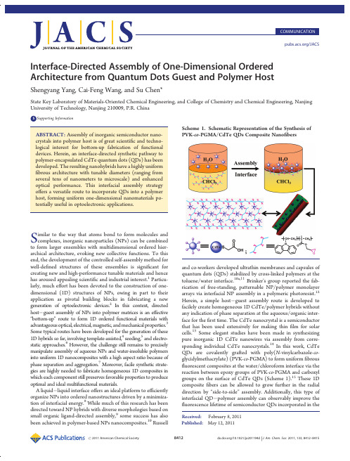
Published:May 12,2011COMMUNICATION /JACSInterface-Directed Assembly of One-Dimensional Ordered Architecture from Quantum Dots Guest and Polymer HostShengyang Yang,Cai-Feng Wang,and Su Chen*State Key Laboratory of Materials-Oriented Chemical Engineering,and College of Chemistry and Chemical Engineering,Nanjing University of Technology,Nanjing 210009,P.R.ChinabSupporting Information ABSTRACT:Assembly of inorganic semiconductor nano-crystals into polymer host is of great scienti fic and techno-logical interest for bottom-up fabrication of functional devices.Herein,an interface-directed synthetic pathway to polymer-encapsulated CdTe quantum dots (QDs)has been developed.The resulting nanohybrids have a highly uniform fibrous architecture with tunable diameters (ranging from several tens of nanometers to microscale)and enhanced optical performance.This interfacial assembly strategy o ffers a versatile route to incorporate QDs into a polymer host,forming uniform one-dimensional nanomaterials po-tentially useful in optoelectronic applications.Similar to the way that atoms bond to form molecules and complexes,inorganic nanoparticles (NPs)can be combined to form larger ensembles with multidimensional ordered hier-archical architecture,evoking new collective functions.To this end,the development of the controlled self-assembly method for well-de fined structures of these ensembles is signi ficant for creating new and high-performance tunable materials and hence has aroused appealing scienti fic and industrial interest.1Particu-larly,much e ffort has been devoted to the construction of one-dimensional (1D)structures of NPs,owing in part to their application as pivotal building blocks in fabricating a new generation of optoelectronic devices.2In this context,directed host Àguest assembly of NPs into polymer matrices is an e ffective “bottom-up ”route to form 1D ordered functional materials with advantageous optical,electrical,magnetic,and mechanical properties.3Some typical routes have been developed for the generation of these 1D hybrids so far,involving template-assisted,4seeding,5and electro-static approaches.6However,the challenge still remains to precisely manipulate assembly of aqueous NPs and water-insoluble polymers into uniform 1D nanocomposites with a high aspect ratio because of phase separation and aggregation.7Moreover,facile synthetic strate-gies are highly needed to fabricate homogeneous 1D composites in which each component still preserves favorable properties to produce optimal and ideal multifunctional materials.A liquid Àliquid interface o ffers an ideal platform to e fficiently organize NPs into ordered nanostructures driven by a minimiza-tion of interfacial energy.8While much of this research has been directed toward NP hybrids with diverse morphologies based on small organic ligand-directed assembly,9some success has also been achieved in polymer-based NPs nanocomposites.10Russelland co-workers developed ultrathin membranes and capsules of quantum dots (QDs)stabilized by cross-linked polymers at the toluene/water interface.10a,11Brinker ’s group reported the fab-rication of free-standing,patternable NP/polymer monolayer arrays via interfacial NP assembly in a polymeric photoresist.12Herein,a simple host Àguest assembly route is developed to facilely create homogeneous 1D CdTe/polymer hybrids without any indication of phase separation at the aqueous/organic inter-face for the first time.The CdTe nanocrystal is a semiconductor that has been used extensively for making thin film for solar cells.13Some elegant studies have been made in synthesizing pure inorganic 1D CdTe nanowires via assembly from corre-sponding individual CdTe nanocrystals.14In this work,CdTe QDs are covalently grafted with poly(N -vinylcarbazole-co -glycidylmethacrylate)(PVK-co -PGMA)to form uniform fibrous fluorescent composites at the water/chloroform interface via the reaction between epoxy groups of PVK-co -PGMA and carboxyl groups on the surface of CdTe QDs (Scheme 1).15These 1D composite fibers can be allowed to grow further in the radial direction by “side-to-side ”assembly.Additionally,this type of interfacial QD Àpolymer assembly can observably improve the fluorescence lifetime of semiconductor QDs incorporated in theScheme 1.Schematic Representation of the Synthesis of PVK-co -PGMA/CdTe QDs Composite Nano fibersReceived:February 8,2011polymeric matrix.It can be expected that this example of both linear axial organization and radial assembly methodology can be applied to fabricate spatial multiscale organic Àinorganic com-posites with desired properties of NPs and polymers.Figure 1a shows a typical scanning electron microscope (SEM)image of PVK-co -PGMA/CdTe QDs composite nano fi-bers obtained at the water/chloroform interface after dialysis.The as-prepared fibers have uniform diameters of about 250nm and typical lengths in the range of several tens to several hundreds of micrometers (Figures 1a and S4Supporting In-formation [SI]).Interestingly,PVK-co -PGMA/CdTe composite fibers can randomly assemble into nestlike ring-shaped patterns (Figures 1b and S5[SI]).Given the interaction among epoxy groups,the formation of nestlike microstructures could be attributed to incidental “head-to-tail ”assembly of composite fibers.Moreover,in order to establish the relationship between the role of epoxy groups and the formation of composite nano fibers,control experiments were performed,in which pure PGMA or PVK was used to couple CdTe QDs.The PGMA/CdTe composites could be obtained with fibrous patterns (Figure S6[SI]),but no fibrous composites were achieved at the biphase interface with the use of PVK under the same conditions.The microstructures and fluorescence properties of PVK-co -PGMA/CdTe composite fibers were further character-ized using laser confocal fluorescence microscopy (LCFM).Confocal fluorescence micrographs of composite fibers show that the di fferently sized QDs have no obvious in fluence on the morphology of composites (Figure 1c Àe).Clearly,uniform and strong fluorescence emission is seen throughout all the samples,and the size-dependent fluorescence trait of CdTe QDs in PVK-co -PGMA matrix remains well.In order to verify the existence and distribution of CdTe QDs in the fibers,transmission electron microscopy (TEM)was employed to examine the assembled structures.Figure 2a shows a TEM image of PVK-co -PGMA/CdTe QDs composite nano fi-bers,indicating each composite fiber shown in Figure 1a was assembled from tens of fine nano fibers.An individual fine nano fiber with the diameter of about 30nm is displayed in Figure 2b,from which we can see that CdTe QDs have been well anchored into the fiber with polymeric protection layer,revealing this graft-form process at the interface e ffectively avoidednon-uniform aggregation in view of well-dispersed CdTe QDs within the composite fiber,consistent with the LCFM observa-tion.Unlike previous works where the nanoparticles were ad-sorbed onto the polymer fibers,16CdTe QDs were expelled from the surface of fibers (∼2.5nm)in our system (Figure 2c),albeit the high percentage of QDs in the polymer host (23wt %)was achieved (Figure S7[SI]).This peculiarity undoubtedly confers CdTe QDs with improved stability.The clear di ffuse rings in the selected area electron di ffraction (SAED)pattern further indicate excellent monodispersion and finely preserved crystalline struc-ture of QDs in the nano fibers (Figure 2d).The SAED data correspond to the cubic zinc blende structure of CdTe QDs.A possible mechanism for the assembly of 1D nanostructure was proposed,as illustrated in Figure S8[SI].The hydrophilic epoxy groups of the PVK-co -PGMA chain in the oil phase orient toward the biphase interface and then react with carboxyl groups on the surface of CdTe QDs in the aqueous phase to a fford premier PVK-co -PGMA/CdTe QDs composites.Such nanocomposites will reverse repeatedly,resulting from iterative reaccumulation of epoxy groups at the interface and the reaction between the active pieces (i.e.,epoxy or carboxyl groups)in the composites with intact CdTe QDs or PVK-co -PGMA,forming well-de fined nano-fibers.The control experiments showing that the diameter of composite fibers increases with the increase in the concentration of PVK-co -PGMA are in agreement with the proposed mechan-ism (Figure S9[SI]).In addition,it is expected that the pure polymeric layer on the surface of the fibers (red rectangular zone in Figure 2c)will allow further assembly of fine fibers into thick fibers,and these fibers also could randomly evolve into rings,forming nestlike microstructures when the “head ”and “tail ”of fibers accidentally meet (Figure 1b).To further examine the assembly behavior of composite fibers,the sample of PVK-co -PGMA/CdTe QDs composite nano fibers were kept at the water/chloroform interface for an additional month in a close spawn bottle at room temperature (Figure S10[SI]).With longer time for assembly,thicker composite fibers with tens of micrometers in diameter were obtained (Figure 3a).These micro-fibers have a propensityto form twisted morphology (Figure 3a,b),Figure 1.(a,b)SEM images of PVK-co -PGMA/CdTe QDs composite nano fibers.(c Àe)Fluorescence confocal microscopy images of PVK-co -PGMA/CdTe QDs composite nano fibers in the presence of di fferently sized QDs:(c)2.5nm,(d)3.3nm,and (e)3.6nm.The excitation wavelengths are 488(c),514(d),and 543nm (e),respectively.Figure 2.(a,b)TEM images of PVK-co -PGMA/CdTe QDs composite nano fibers,revealing composite nano fiber assemblies.(c)HRTEM image and (d)SAED pattern of corresponding PVK-co -PGMA/CdTe QDs composite nano fibers.while their re fined nanostructures still reveal relatively parallel character and con firm the micro fibers are assembled from countless corresponding nano fibers (Figure 3c).The corresponding LCFM image of an individual micro fiber is shown in Figure 3d (λex =488nm),indicating strong and homogeneous green fluorescence.Another indication is the fluorescent performance of PVK-co -PGMA/CdTe QDs composite micro fibers (Figure 4a).The fluorescent spectrum of composite fibers takes on emission of both PVK-co -PGMA and CdTe QDs,which suggests that this interfacial assembly route is e ffective in integrating the properties of organic polymer and inorganic nanoparticles.It is worth noting that there is a blue-shift (from 550to 525nm)and broadening of the emission peak for CdTe QDs upon their incorporation into polymeric hosts,which might be ascribed to the smaller QD size and less homogeneous QD size distribution resulting from the photooxidation of QD surfaces.17Since the emission spectra of PVK-co -PGMA spectrally overlap with the CdTe QD absorption (Figure S11[SI]),energy transfer from the copolymer to the CdTe QDs should exist.18However,the photoluminescence of PVK-co -PGMA does not vanish greatly in the tested sample in comparison with that of polymer alone,revealing inferior energy transfer between the polymer host and the QDs.Although e fficient energy transfer could lead to hybrid materials that bring together the properties of all ingredients,18it is a great hurdle to combine and keep the intrinsic features of all constituents.19In addition,by changing the polymeric compo-nent and tailoring the element and size of QDs,it should be possible to expect the integration of organic and inorganic materials with optimum coupling in this route for optoelectronic applications.Finally,to assess the stability of CdTe QDs in the composite micro fibers,time-resolved photoluminescence was performed using time-correlated single-photon counting (TCSPC)parative TCSPC studies for hybrid PVK-co -PGMA/CdTe QDs fibers and isolated CdTe QDs in the solid state are presented in Figure 4b.We can see that the presence of PVK-co -PGMA remarkably prolongs the fluorescence lifetime (τ)of CdTe QDs.Decay traces for the samples were well fittedwith biexponential function Y (t )based on nonlinear least-squares,using the following expression.20Y ðt Þ¼R 1exp ðÀt =τ1ÞþR 2exp ðÀt =τ2Þð1Þwhere R 1,R 2are fractional contributions of time-resolved decaylifetimes τ1,τ2and the average lifetime τhcould be concluded from the eq 2:τ¼R 1τ21þR 2τ22R 1τ1þR 2τ2ð2ÞFor PVK-co -PGMA/CdTe QDs system,τh is 10.03ns,which is approximately 2.7times that of isolated CdTe QDs (3.73ns).Photooxidation of CdTe QDs during the assembly process can increase the surface states of QDs,causing a delayed emission upon the carrier recombination.21Also,the polymer host in this system could prevent the aggregation of QDs,avoid self-quench-ing,and delay the fluorescence decay process.22The increased fluorescence lifetime could be also ascribed to energy transfer from PVK-co -PGMA to CdTe QDs.18c The result suggests that this host Àguest assembly at the interface could find signi ficant use in the fabrication of QDs/polymer hybrid optoelectronic devices.In summary,we have described the first example of liquid/liquid interfacial assembly of 1D ordered architecture with the incorporation of the QDs guest into the polymer host.The resulting nanohybrids show a highly uniform fibrous architecture with tunable diameter ranging from nanoscale to microscale.The procedure not only realizes the coexistence of favorable properties of both components but also enables the fluorescence lifetime of QDs to be enhanced.This interesting development might find potential application for optoelectronic and sensor devices due to high uniformity of the 1D structure.Further e fforts paid on optimal regulation of QDs and polymer composition into 1D hybrid nanostructure could hold promise for the integration of desirable properties of organic and inorganic compositions for versatile dimension-dependent applications.In addition,this facile approach can be easily applied to various semiconductor QDs and even metal NPs to develop highly functional 1D nanocomposites.’ASSOCIATED CONTENTbSupporting Information.Experimental details,FT-IR,GPC,UV Àvis,PL,SEM,TGA analysis,and complete ref 9c.This material is available free ofcharge via the Internet at .Figure 3.(a,b)SEM and (c)FESEM images of PVK-co -PGMA/CdTe QDs composite micro fibers.(d)Fluorescence confocal microscopy images of PVK-co -PGMA/CdTe QDs composite micro fibers inthe presence of green-emitting QDs (2.5nm).Figure 4.(a)Fluorescence spectra of PVK-co -PGMA,CdTe QD aqueous solution,and PVK-co -PGMA/CdTe QDs composite micro-fibers.(b)Time-resolved fluorescence decay curves of CdTe QDs (2.5nm diameter)powders (black curve)and the corresponding PVK-co -PGMA/CdTe QDs composite micro fibers (green curve)mea-sured at an emission peak maxima of 550nm.The samples were excited at 410nm.Biexponential decay function was used for satisfactory fitting in two cases (χ2<1.1).’AUTHOR INFORMATIONCorresponding Authorchensu@’ACKNOWLEDGMENTThis work was supported by the National Natural Science Foundation of China(21076103and21006046),National Natural Science Foundation of China-NSAF(10976012),the Natural Science Foundations for Jiangsu Higher Education Institutions of China(07KJA53009,09KJB530005and10KJB5 30006),and the Priority Academic Program Development of Jiangsu Higher Education Institutions(PAPD).’REFERENCES(1)(a)Kashiwagi,T.;Du,F.;Douglas,J.F.;Winey,K.I.;Harris, R.H.;Shields,J.R.Nat.Mater.2005,4,928.(b)Shenhar,R.;Norsten, T.B.;Rotello,V.M.Adv.Mater.2005,17,657.(c)Akcora,P.;Liu,H.; Kumar,S.K.;Moll,J.;Li,Y.;Benicewicz,B.C.;Schadler,L.S.;Acehan, D.;Panagiotopoulos,A.Z.;Pryamitsyn,V.;Ganesan,V.;Ilavsky,J.; Thiyagarajan,P.;Colby,R.H.;Douglas,J.F.Nat.Mater.2009,8,354.(d)Dayal,S.;Kopidakis,N.;Olson,D.C.;Ginley,D.S.;Rumbles,G. J.Am.Chem.Soc.2009,131,17726.(e)Lin,Y.;B€o ker,A.;He,J.;Sill,K.; Xiang,H.;Abetz,C.;Li,X.;Wang,J.;Emrick,T.;Long,S.;Wang,Q.; Balazs,A.;Russell,T.P.Nature2005,434,55.(f)Park,S.;Lim,J.ÀH.; Chung,S.W.;Mirkin,C.A.Science2004,303,348.(g)Mai,Y.; Eisenberg,A.J.Am.Chem.Soc.2010,132,10078.(h)Mallavajula, R.K.;Archer,L.A.Angew.Chem.,Int.Ed.2011,50,578.(i)Kim,J.;Piao, Y.;Hyeon,T.Chem.Soc.Rev.2009,38,372.(2)(a)Xia,Y.;Yang,P.;Sun,Y.;Wu,Y.;Mayers,B.;Gates,B.;Yin, Y.;Kim,F.;Yan,H.Adv.Mater.2003,15,353.(b)Lu,X.;Wang,C.;Wei, Y.Small2009,5,2349.(c)Nie,Z.;Fava,D.;Kumacheva,E.;Zou,S.; Walker,G.C.;Rubinstein,M.Nat.Mater.2007,6,609.(3)(a)Huynh,W.U.;Dittmer,J.J.;Alivisatos,A.P.Science2002, 295,2425.(b)Balazs,A.C.;Emrick,T.;Russell,T.P.Science2006, 314,1107.(c)Ramanathan,T.;Abdala,A.A.;Stankovich,S.;Dikin, D.A.;Herrera-Alonso,M.;Piner,R.D.;Adamson,D.H.;Schniepp, H.C.;Chen,X.;Ruoff,R.S.;Nguyen,S.T.;Aksay,I.A.;Prud’homme, R.K.;Brinson,L.C.Nat.Nanotechnol.2008,3,327.(d)Tomczak,N.; Janczewski,D.;Han,M.;Vancso,G.J.Prog.Polym.Sci.2009,34,393.(e)Zhao,Y.;Thorkelsson,K.;Mastroianni,A.J.;Schilling,T.;Luther, J.M.;Rancatore,B.J.;Matsunaga,K.;Jinnai,H.;Wu,Y.;Poulsen,D.; Frechet,J.M.J.;Alivisatos,A.P.;Xu,T.Nat.Mater.2009,8,979.(f) Colfen,H.;Mann,S.Angew.Chem.,Int.Ed.2003,42,2350.(g)Sone,E.D.;Stupp,S.I.J.Am.Chem.Soc.2004,126,12756.(4)Chan,C.S.;De Stasio,G.;Welch,S.A.;Girasole,M.;Frazer,B.H.;Nesterova,M.V.;Fakra,S.;Banfield,J.F.Science2004,303,1656.(5)Tran,H.D.;Li,D.;Kaner,R.B.Adv.Mater.2009,21,1487.(6)Yuan,J.;M€u ller,A.H.E.Polymer2010,51,4015.(7)(a)Greenham,N.C.;Peng,X.;Alivisatos,A.P.Phys.Rev.B 1996,54,17628.(b)Lopes,W.A.;Jaeger,H.M.Nature2001,414,735.(c)Gupta,S.;Zhang,Q.;Emrick,T.;Balazs,A.Z.;Russell,T.P.Nat. Mater.2006,5,229.(8)(a)Wang,X.;Zhuang,J.;Peng,Q.;Li,Y.Nature2005,437,121.(b)Huang,J.;Kaner,R.B.J.Am.Chem.Soc.2004,126,851.(c)Binder, W.H.Angew.Chem.,Int.Ed.2005,44,5172.(d)Capito,R.M.;Azevedo, H.S.;Velichko,Y.S.;Mata,A.;Stupp,S.I.Science2008,319,1812.(e)Yin,Y.;Skaff,H.;Emrick,T.;Dinsmore,A.D.;Russell,T.P.Science 2003,299,226.(f)Arumugam,P.;Patra,D.;Samanta,B.;Agasti,S.S.; Subramani,C.;Rotello,V.M.J.Am.Chem.Soc.2008,130,10046.(g)Hou,L.;Wang,C.F.;Chen,L.;Chen,S.J.Mater.Chem.2010, 20,3863.(9)(a)Duan,H.;Wang,D.;Kurth,D.G.;Mohwald,H.Angew. Chem.,Int.Ed.2004,43,5639.(b)B€o ker,A.;He,J.;Emrick,T.;Russell,T.P.Soft Matter2007,3,1231.(c)Russell,J.T.;et al.Angew.Chem.,Int. Ed.2005,44,2420.(10)(a)Lin,Y.;Skaff,H.;B€o ker,A.;Dinsmore,A.D.;Emrick,T.; Russell,T.P.J.Am.Chem.Soc.2003,125,12690.(b)B€o ker,A.;Lin,Y.; Chiapperini,K.;Horowitz,R.;Thompson,M.;Carreon,V.;Xu,T.; Abetz,C.;Skaff,H.;Dinsmore,A.D.;Emrick,T.;Russell,T.P.Nat. Mater.2004,3,302.(11)Skaff,H.;Lin,Y.;Tangirala,R.;Breitenkamp,K.;B€o ker,A.; Russell,T.P.;Emrick,T.Adv.Mater.2005,17,2082.(12)Pang,J.;Xiong,S.;Jaeckel,F.;Sun,Z.;Dunphy,D.;Brinker,C.J.J.Am.Chem.Soc.2008,130,3284.(13)Fulop,G.;Doty,M.;Meyers,P.;Betz,J.;Liu,C.H.Appl.Phys. Lett.1982,40,327.(14)(a)Tang,Z.;Kotov,N.A.;Giersig,M.Science2002,297,237.(b)Zhang,H.;Wang,D.;Yang,B.;M€o hwald,H.J.Am.Chem.Soc.2006, 128,10171.(c)Yang,P.;Ando,M.;Murase,N.Adv.Mater.2009, 21,4016.(d)Srivastava,S.;Santos,A.;Critchley,K.;Kim,K.-S.; Podsiadlo,P.;Sun,K.;Lee,J.;Xu,C.;Lilly,G.D.;Glotzer,S.C.;Kotov, N.A.Science2010,327,1355.(15)Reis,A.V.;Fajardo,A.R.;Schuquel,I.T.A.;Guilherme,M.R.; Vidotti,G.J.;Rubira,A.F.;Muniz,.Chem.2009,74,3750.(16)(a)Djalali,R.;Chen,Y.;Matsui,H.J.Am.Chem.Soc.2002, 124,13660.(b)George,J.;Thomas,K.G.J.Am.Chem.Soc.2010, 132,2502.(17)(a)Yang,S.;Li,Q.;Chen,L.;Chen,S.J.Mater.Chem.2008, 18,5599.(b)Wang,Y.;Herron,N.J.Phys.Chem.1991,95,525.(c)Zhang,Y.;He,J.;Wang,P.N.;Chen,J.Y.;Lu,Z.J.;Lu,D.R.;Guo,J.; Wang,C.C.;Yang,W.L.J.Am.Chem.Soc.2006,128,13396.(d)Carrillo-Carri o n,C.;C a rdenas,S.;Simonet,B.M.;Valc a rcel,M. mun.2009,5214.(18)(a)Tessler,N.;Medvedev,V.;Kazes,M.;Kan,S.;Banin,U. Science2002,295,1506.(b)Zhang,Q.;Atay,T.;Tischler,J.R.;Bradley, M.S.;Bulovi c,V.;Nurmikko,A.V.Nat.Nanotechnol.2007,2,555.(c)Lutich,A.A.;Jiang,G.X.;Susha,A.S.;Rogach,A.L.;Stefani,F.D.; Feldmann,J.Nano Lett.2009,9,2636.(19)Li,M.;Zhang,J.;Zhang,H.;Liu,Y.;Wang,C.;Xu,X.;Tang,Y.; Yang,B.Adv.Funct.Mater.2007,17,3650.(20)Schr€o der,G.F.;Alexiev,U.;Grubm€u ller,H.Biophys.J.2005, 89,3757.(21)(a)Zhong,H.Z.;Zhou,Y.;Ye,M.F.;He,Y.J.;Ye,J.P.;He,C.; Yang,C.H.;Li,Y.F.Chem.Mater.2008,20,6434.(b)Sun,H.;Zhang, H.;Zhang,J.;Ning,Y.;Yao,T.;Bao,X.;Wang,C.;Li,M.;Yang,B. J.Phys.Chem.C2008,112,2317.(22)Kagan,C.R.;Murray,C.B.;Bawendi,M.G.Phys.Rev.B1996, 54,8633.。
3_氨丙基三乙氧基硅烷表面修饰的磁性Fe_3O_4纳米粒子合成与表征

Vol 136No 112・26・化 工 新 型 材 料N EW CH EMICAL MA TERIAL S 第36卷第12期2008年12月新材料与新技术基金项目:国家自然科学基金(20476065;20736004);国家教委留学回国基金;中国科学院过程工程研究所多相反应国家重点实验室基金(200322);中国科学院煤炭化学研究所煤转化国家重点实验室基金(20062902);合成化学江苏省重点实验室基金;苏州大学基础课化学实验教学中心;南京医科大学研发基金(N Y0586)作者简介:冯斌(1984-),男,硕士研究生,应用化学专业,研究方向磁性功能材料。
32氨丙基三乙氧基硅烷表面修饰的磁性Fe 3O 4纳米粒子合成与表征冯 斌1 任志强1 屈晶苗1 洪若瑜1,2 李洪钟2 魏东光3(1.苏州大学化学化工学院,江苏省有机合成重点实验室,苏州215123;2.中科院过程工程研究所多相反应国家重点实验室,北京100080;3.哈佛大学工程与应用科学学院,纳米尺寸研究中心,马萨诸塞州02139.)摘 要 以FeCl 3、FeSO 4为铁源,利用改进共沉淀法合成磁性纳米Fe 3O 4,在其制备的过程中加入水合肼充当还原剂和沉淀剂,采用32氨丙基三乙氧基硅烷(A PTES ),通过硅烷化反应以化学键的方式结合Fe 3O 4纳米颗粒,获得表面氨基化的磁性Fe 3O 4纳米复合颗粒。
并用XRD 、IR 、TEM 、VSM 等分析手段深入研究了AP TES 修饰前后磁性纳米颗粒结构和性能影响。
结果表明A PTES 成功包覆到磁性纳米粒子表面,其包覆率为21%;磁性颗粒粒径为20nm ,晶型为反立方尖晶石型;磁性颗粒具有很好的分散性,其磁化率为2.36×10⁻⁶,饱和磁化强度达60.8mT 。
关键词 磁性纳米颗粒,共沉淀法,表面修饰,氨基化Preparation and characterization of (32aminopropyl)triethoxysilane coatedmagnetite nanoparticlesFeng Bin 1 Ren Zhiqiang 1 Qu Jingmiao 1 Hong Ruoyu 1,2 Li Hongzhong 2 Wei Dongguang 3(11Chem.Eng.Dept.&Key Lab.of Organic Synt hesis of Jiangsu Prov.,Soochow Univ.,SIP ,Suzhou 215123;21State Key Lab.of Multip hase Reactio n ,Inst.of Proc.Eng.,Chinese Academy of Sciences ,Beijing 100080;31Center for Nanoscale Sys.,School of Eng.&Appl.Sci.,Harvard Univ.,11Oxford St.,Cambridge ,MA 02139)Abstract Using FeCl 3and FeSO 4as iron sources ,Fe 3O 4magnetic nanoparticles were synthesized by modifiedchemical co 2precipitation.Hydrazine hydrate as reducing agent and precipitator was added in the process of preparation.Magnetite nanoparticles coated with (32aminopropyl )triethoxysilane ,were prepared by silanization reaction and character 2ized by XRD ,TEM ,IR ,VSM et al.The result showed that nanoparticles were coated successf ully by A PTES ,the coat 2ing percentage was about 21%,the mean size of the magnetic nanoparticles were about 20nm ,and their morphology was inverse spinel.The A PTES coated magnetite nanoparticles demonstrated excellent dispersibility ,and had susceptibility of 2136×10-6and saturation magnetization of 6018m T.K ey w ords magnetite nanoparticle ,coprecipitation ,surface modification ,amino 2functionalization 纳米材料,特别是磁性纳米粒,是物理、化学、化工、材料科学与工程和生物医药等领域研究的热点[125]。
剪切增稠液及其复合材料的研究进展
橡 胶 工 业CHINA RUBBER INDUSTRY312第71卷第4期Vol.71 No.42024年4月A p r.2024剪切增稠液及其复合材料的研究进展陈柏宇1,管登高1,彭 燕2,刘 涛2(1.成都理工大学 材料与化学化工学院,四川 成都 610000;2.中国工程物理研究院 化工材料研究所,四川 绵阳 621000)摘要:剪切增稠液(STF )作为新一代智能耗能材料广泛应用于抗刺扎、抗冲击和阻尼减振等领域。
介绍STF 的特性和剪切增稠机理,综述STF 复合材料的制备方式,包括浸渍或喷涂、夹层或填充、共混以及胶囊化;分析STF 复合材料的抗刺扎性能、抗冲击性能、阻尼减振性能与应用。
建议进一步探索STF 的剪切增稠机理,研发对环境不敏感、长使用寿命、可在高冲击速率下应用、磁流变性或电流变性的STF 复合材料。
关键词:剪切增稠液;复合材料;抗刺扎性能;抗冲击性能;阻尼减振性能;共混;胶囊化中图分类号:TQ336.4+2 文章编号:1000-890X (2024)04-0312-08文献标志码:A DOI :10.12136/j.issn.1000-890X.2024.04.03121931年R.V.WILLIAMSON [1]在胶体分散体系中发现了异常流变行为,当剪切力到达一定阈值时,硬球分散液的黏度会出现急剧增大现象。
之后H.FREUNDLICH 等[2]也验证了这一现象,该现象被描述为剪切增稠(由T.GILLESPIE [3]于1966年提出)。
由于突然增大的黏度会破坏仪器设备、阻塞输送流体的管道、使涂料涂覆不均匀,当时多被视为工业生产中的不利现象。
后来随着研究的不断深入,该现象在防护和阻尼减振等领域潜在的应用价值被发现,剪切增稠材料的制备也受到关注。
剪切增稠液(STF )是一种典型的剪切增稠材料,通常是由极性溶剂以及纳米或微米颗粒组成的颗粒悬浮液。
这种悬浮液在正常情况下呈液态,具有较好的流动性,但当所受的剪切力到达一定阈值时,悬浮液黏度急剧增大,甚至出现类固态的转变,而当剪切力加载取消后,悬浮液又快速恢复到初始状态,变为可流动的液体。
溴到硼酸酯
Materials Chemistry C
Published on 20 November 2014. Downloaded on 08/12/2016 07:54:22.
PAPER
View Article Online
View Journal | View Issue
Cite this: J. Mater. Chem. C, 2015, 3, 861
However, these oligouorene functionalized oligomers may suffer from the unwanted long wavelength emission under long-term device operation, similar to polyuorene-based macromolecules.34–36
Received 26th September 2014 Accepted 17th November 2014 DOI: 10.1039/c4tc02173h /MaterialsC
Starburst 4,40,400-tris(carbazol-9-yl)triphenylamine-based deep-blue fluorescent emitters with tunable oligophenyl length for solution-processed undoped organic lightemitting diodes†
Introduction
Since 1987, organic light-emitting diodes (OLEDs) have attracted tremendous attention due to their potential applications in at-panel displays and solid-state lightings.1–10 To achieve fullcolor displays, three primary RGB luminescent materials with excellent stability, efficiency and color purity are required. With respect to green and red counterparts, it seems to be a big challenge to develop blue emitters, especially deep-blue ones that have a Commission Internationale de l'Eclairage (CIE) y coordinate value of <0.10, because the intrinsic wide bandgap would inevitably result in inefficient charge injection to an emitting layer (EML).11 Therefore, great efforts should be paid to the design of deep-blue emitters to push forward the commercialization of full-color OLEDs.
晶带轴
In Situ Growth of Self-Assembled and Single In2O3Nanosheets onthe Surface of Indium GrainsHeqing Yang,*,†Ruigang Zhang,†Hongxing Dong,†Jie Yu,†Wenyu Yang,†andDichun Chen‡Key Laboratory of Macromolecular Science of Shaanxi Pro V ince,School of Chemistry and MaterialsScience,Shaanxi Normal Uni V ersity,Xi’an710062,China,and Ad V anced Material Analysis and TestCenter,Xi’an Uni V ersity of Technology,Xi’an710048,ChinaRecei V ed January7,2007;Re V ised Manuscript Recei V ed May15,2008ABSTRACT:Self-assembled In2O3nanosheet networks andflowerlike nanoarchitectures,as well as single In2O3nanosheets,have been grown in situ on indium substrate by heating indium grains at900-950°C under theflow of O2in the presence of a small quantity of P2O5.The as-synthesized In2O3nanosheets were characterized by transmission electron microscopy,scanning electron microscopy,and Raman spectrum.It was found that the In2O3nanosheets were single crystals with body-centered cubic structure and dimensions of about0.5-3µm.A possible mechanism for the In2O3nanosheet growth was also proposed on the basis of the results of the present and previous works.This mechanism not only can explain all the experimental observations but also helps to clarify the growth mechanism of other nanostructures in the gas phase.A strong and narrow photoluminescent(PL)peak at428nm was observed from the nanosheets,which is attributed to radiative recombination between an electron on an oxygen vacancy and a hole on an indium-oxygen vacancy center in the In2O3nanosheets.1.IntroductionSynthesis of different dimensional(D)nanostructures,such as0D quantum dots,1D nanowires and nanotubes,or2D nanosheets and nanodisks are of great importance in studying the physical properties of nanomaterials or constructing func-tional nanodevices.1Indium oxide(In2O3),an n-type semicon-ductor with a wide bandgap of about3.6eV,has been widely used as window heater,solar cell,andflat-panel display materials2and gas sensors.3Since the discovery of indium oxide nanobelts in2001,4research in In2O3nanostructures,including nanowires,nanotubes,nanobelts,octahedrons,nanocubes,and core-shell nanoparticles has been rapidly expanded due to their potential application in high sensitivity sensor,optoelectronic,field emission,and electronic devices.The indium oxide nanowires have been used to fabricatedfield-effect transistors,5,6 nanoscale chemical sensors,7and biosensing devices.8Up to now,many kinds of In2O3nanostructures have been synthesized via thermal evaporation of In2O3,chemical vapor deposition(CVD),pulsed laser deposition(PLD),and wet chemical methods.In2O3nanobelts were synthesized via a thermal evaporation of In2O3powders at1400°C4or via a CVD using thermal oxidation reactions of In.9In2O3nanowires can be obtained by the CVD of thermal oxidations10–12and reductions,6,13,14by a laser ablation of InAs target,15or by triblock copolymer and porous alumina template methods.16 Additionally,single-crystalline In2O3nanotubesfilled with metallic In,17In2O3nanocrystal chains,and nanowire networks18 were synthesized by evaporating a mixture of In/In2O3or C/In2O3.Hollow In2O3nanotubes were grown in porous alumina membranes by a sol-gel process.19Aligned1D In2O3structures with a triangular cross-section were synthesized by a metal-organic chemical vapor deposition method(MOVCD).20In addition to the quasi-1D nanostructures,0D quantum dots such as quasi-monodisperse In2O3nanoparticles,21,22nanocubes,23In2O3octahedron,24,25and highly ordered In2O3coated In core-shell nanoparticles26were prepared via wet chemical methods,21–23CVD,24,25and a three-step oxidation process of In nanoparticle arrays.26However,to our knowledge,synthesis of2D In2O3nanostructures except for thinfilms has not been reported until now.Herein we report the synthesis of self-assembled and single In2O3nanosheets by an in situ thermal oxidation method.These sheet-like nanostructures were directly grown on the surfaces of indium grains by heating indium metal at900-950°C in an oxygen gas atmosphere in the presence of a small quantity of pared with CVD,MOCVD,and PLD,this procedure does not include In or In2O vapor transport and condensation processes and does not require very high temperature and low pressure.Growth mechanism and photoluminescence of the In2O3nanosheets were investigated in detail.2.Experimental Procedures2.1.Sample Preparation.The In2O3nanosheets were synthesized by a simple thermal oxidation of indium metal in a conventionalhorizontal tube furnace.In a typical experiment,In metal grains(purity99.999%)were treated in an aqueous1.0M HCl solution for30s andthen washed with absolute ethanol in an ultrasonic bath for15min.The grain was placed on a silicon wafer,and the silicon wafer wasplaced in a quartz boat containing a small quantity of P2O5(formed byheating a quartz boat containing about2-5mg of red phosphorus to500°C and then maintaining it at500°C for0.5h in an O2gasatmosphere).The boat was placed at the center of a quartz tube thatwas inserted in a horizontal tube furnace,where the temperature andgrowth time were controlled.Prior to heating,high-purity N2(99.999%)was introduced into the quartz tube with a constantflow rate of3.0L/h to purge the O2inside.After20min,the system was heated to900°C for60min under a constantflow of N2gas at a rate of1.0L/h. Afterward,1.0L/h O2was introduced into the chamber,and thetemperature was kept at900°C for2h.After the system cooled toroom temperature under a constantflow of N2gas at a rate of1.0L/h,a large amount of ashen products were found on the surface of theindium grains.2.2.Characterization.The synthesized products were characterized and analyzed by X-ray diffraction(XRD;Rigaku DMX-2550/PC X-ray diffractometer),Raman spectra(Jobin Yvon LabRAM HR800and*Corresponding author.Fax:+86-29-85307774.Tel:+86-29-85303943.E-mail address:hqyang@.†Shaanxi Normal University.‡Xi’an University of Technology.10.1021/cg070019e CCC:$40.75 XXXX American Chemical SocietyPublished on Web 07/23/2008Nicolet Alemga dispersive Raman spectrometer),scanning electron microscopy (SEM;FEI Quanta 200),and high-resolution transmission electron microscopy (HRTEM;JEOL JEM-3010at 300kV).Samples for HRTEM were prepared by dispersing a powdered In 2O 3product on a carbon-coated copper grid.An energy-dispersive X-ray spectros-copy (EDS)facility attached to the SEM and TEM was employed to analyze the chemical composition.Photoluminescent (PL)spectra were measured at room temperature in an Edinburgh FLS920fluorescence spectrophotometer with a Xe lamp using excitation at 380nm.3.Results and DiscussionFigure 1a -c shows typical SEM images of as-prepared samples grown at 900°C for 2h at low and high magnifications.These In 2O 3nanosheets were randomly and fairly uniformly distributed on the surface of the In grain.Figure 1c clearly shows that In 2O 3nanosheets are oriented upward with respect to the underlying substrate and have irregularly shaped morphologies with maximum dimension of about 0.5-3.0µm on the bottom,gradually narrowing to the top.The minimum thickness of the In 2O 3sheets on the top is tens of nanometers.In addition to the dispersed In 2O 3nanosheets,a small quantity of intercrossed In 2O 3nanosheet networks are also observed in some areas on the surface of the In grains.The typical morphology of these self-assembled In 2O 3nanosheets is shown in Figure 2.Figure 2a-b shows the low-and high-magnification SEM images,respectively.Figure 2b clearly shows that the network is constructed of nanosheets with heights ranging from 0.5to 1.2µm.The nanosheets intercross with each other to form complicated networks.When the reaction temperature was increased from 900to 950°C,a few interesting flowerlike In 2O 3nanoarchitectures were observed on the surface of the In grains.Typical SEM micrographs of the flowerlike In 2O 3nanoarchi-tectures at low and high magnifications are presented in Figure 3a,b.From Figure 3a,b,it is evident that In 2O 3nanoflowers consist of sheetlike nanostructures.The In 2O 3nanosheets possessmainly fan-shaped morphologies and are 0.5-5.5µm in length and 0.6-3.2µm in height.Figure 4a shows the XRD pattern of the samples grown at 900°C for 2h in an O 2gas atmosphere.Sixteen peaks at 2θ)30.5°,32.8°,35.3°,37.6°,41.7°,43.6°,45.5°,49.1°,50.9°,52.8°,56.0°,59.0°,60.5°,62.1°,63.5°,and 64.4°are observed from Figure 4a.According to JCPDS card no.06-0461,the products are In 2O 3with body-centered cubic structure,and these peaks are assigned to (222),(321),(400),(411),(332),(422),(431),(521),(440),(433),(611),(541),(622),(631),(444),and (543)diffraction lines of cubic In 2O 3phases,respectively.RamanFigure 1.SEM images of as-prepared samples grown at 900°C for 2h at differentmagnifications.Figure 2.Low-(a)and high-magnification (b)SEM images of the intercrossed In 2O 3nanosheetnetworks.Figure 3.Low-(a)and high-magnification (b)SEM micrographs of the flowerlike In 2O 3nanoarchitectures grown at 950°C for 2h.Figure 4.XRD pattern (a)and Raman spectrum (b)of the samples grown at 900°C for 2h.B Crystal Growth &Design,Vol.xxx,No.xx,XXXX Yang et al.scattering,due to its sensitivity to crystallization in nanostruc-tures,was also measured for the In 2O 3nanosheets.Figure 4b shows the Raman spectrum of the samples grown at 900°C for 2h excited with an Ar +laser at 514nm at room temperature.The five peaks at 126,301,358,489,and 622cm -1can be identified to be those of the cubic In 2O 3.27XRD and Raman indicate that the products obtained are In 2O 3nanosheets with cubic structure.The characterization of individual In 2O 3nanosheets was achieved in further detail using TEM.Figure 5a shows the TEM image of a quasi-rectangular In 2O 3nanosheet.The nanosheet is 650nm in length and 520nm in width.The contrast on a whole sheet is inhomogenous,which indicates that the thick-nesses of the sheet at the root and the center are greater than that at the top and side edges,as observed by SEM.The corresponding selected area electron diffraction (SAED)pattern is shown in Figure 5b;it can be indexed as a cubic In 2O 3along the [125]axis,consistent with the XRD and Raman results.The HRTEM image of the In 2O 3nanosheet is displayed in Figure5c.The fringe spacing is about 0.42nm,corresponding to the (121j )crystal planes of the cubic In 2O 3.The chemical composi-tion of the In 2O 3nanosheet was verified by an EDS facility attached to the TEM.The EDS data curve is shown in Figure 5d,in which In,O,and Cu elements were marked.The Cu-related peak is due to the presence of the Cu grids.So,the nanosheet consists of indium and oxygen.These results indicate that the nanosheets are a single-crystalline with body-centered cubic structure.To identify whether there was P 2O 5on the surface of the In 2O 3nanosheets,an EDS facility attached to the SEM was employed to analyze the chemical composition of the In 2O 3nanosheets obtained by heating indium grains at 900°C for 2h in an O 2gas atmosphere in the presence of a small quality P 2O 5,and the results are shown in Figure 6.Figure 6b-c shows EDS spectra from the marked region and dot in panel a,respectively.The peaks of In,P,and O elements were observed from the EDS spectra.It indicates that there was P 2O 5on the surface of In 2O 3nanosheets.The P-related peak was not found in the EDS spectrum (Figure 5d)obtained by using an EDS facility attached to the TEM.The disappearance of the P-related peak may because that the P 2O 5was dissolved in ethanol during prepara-tion of the samples for TEM analysis.To illuminate the role of P 2O 5in the formation of In 2O 3nanosheets,the products obtained by heating indium grains at 900°C for 2h in an O 2gas atmosphere in the absence of P 2O 5were characterized with SEM and Raman,and results are shown in Figure 7.We found that there are octahedra instead of nanosheets on the surface of the indium grain in the SEM image (Figure 7a),indicating that P 2O 5plays an important role in the growth process of In 2O 3nanosheets.Figure 7b is Raman spectra of the sample.In the Raman spectra,we observed five scattering peaks at 130,306,366,495,and 628cm -1,which can be identified to be those of the cubic In 2O 3.27It indicates that metallic In was oxidized to form an In 2O 3octahedral layer on the surface of In grains when indium grains were heated at 900°C in an O 2gas atmosphere without P 2O 5.In order to understand the formation process of the In 2O 3nanosheets,time-dependent experiments were carried out,and the resultant products were analyzed by SEM and Raman spectra.The representative SEM images of the products prepared at certain reaction time intervals are shown in Figure 8.A large quantity of spherical particles was seen on the surface of the In grains obtained by heating at 900°C for 2min (Figure 8a).When the reaction time was prolonged to10min,these particles aggregated with each other to form large congeries (Figure 8b).In addition to the congeries,a small quantity of In 2O 3nanosheets was observed on the surface of the congeries (Figure 8c).When the reaction time was increased to 30min,a large quantity of In 2O 3nanosheets were observed on the surface of the In grains (Figure 8d).Figure 9shows the Raman spectra from the samples reacted for 2,10,and 30min excited with an Nd:YVO 4laser at 532nm at room temperature,which indicates that the nanoparticles and nanosheets are In 2O 3with a cubic structure.27The growth process for the In 2O 3is similar to the growth of BN nanowires through the reaction of a mixed gas of N 2and NH 3over R -FeB particles 28and the growth of In 2O 3nanowires through the reaction of an O 2gas over indium grains coated on a Au film.29The P 2O 5may be a catalyst for the growth of In 2O 3nanosheets.On the basis of the investigations described above,a possible mechanism to form In 2O 3nanosheets was proposed with reference to the preparation of Ti-doped CeO 2nanopar-ticles,30growth of carbon tubes via surface diffusion,31and growth of silicon nanowires via a solid -liquid -solid(S-L-S)Figure 5.TEM images and SAED pattern of the In 2O 3nanosheets synthesized at 900°C for 2h:(a)typical image of a single In 2O 3nanosheet;(b)corresponding SAED pattern;(c)HRTEM image;(d)EDS spectrum.Self-Assembled and Single In 2O 3Nanosheets on In Grains Crystal Growth &Design,Vol.xxx,No.xx,XXXX Cmechanism.32As illustrated in Figure 10,during heating under the flow of N 2,the In metal was melted to form liquid In (the melting point of In metal is 156.6°C);P 2O 5was vaporized and reacted with surface In of In grains to produce In -P -O liquid-phase layers.When the temperature was increased to 900°C,O 2gas was introduced into the chamber and reacted with the surface In rapidly to produce In 2O 3.According to Feng,30Tian,31a and Hofmann 31b and their co-workers,the In 2O 3congregated,nucleated,and grew into In 2O 3nanoparticles coated with an In -P -O liquid-phase layer on the liquid In surface via surface diffusion (Figure 10c).The In 2O 3nanoparticles coated with an In -P -O liquid-phase layer evolved into large particles driven by the minimization of surface energy.The In -P -O liquid-phase layers reacted with the In 2O 3core to form In -P -O droplets (Figure 10e)on the surface of the large particles.When the In 2O 3in the droplets reach a saturated concentration,crystalline In 2O 3nanosheets begin to grow from the droplets via the S-L-S mechanism (Figure 10f).The growth mechanism may be characterized by the growth at the roots of the nanosheets.The underlying In 2O 3core provides the neces-sary feeding materials for the nanosheet growth.The surrounding In 2O 3of the In 2O 3core was consumed and transported through the surface of In metal for the continuous growth of the In 2O 3nanosheets.The oxidation reaction of the surface In of indium grains provides In 2O 3to maintain the surface diffusion and nanosheet growth.After the reaction,the shape of the In grain is also spherical (Figure 1a),which indicates that the oxidation of metallic In as well as nucleation and growth of In 2O 3nanosheets occurred on the metallic In surface.During the growth of In 2O 3nanosheets in addition to the S-L-S growth mechanism,surrounding In 2O 3of the In 2O 3sheets was trans-ported through the surface of In 2O 3particles and nanosheets to the top and side edges of nanosheets,and nucleated and grew (Figure 10g).There is a concentration gradient of In 2O 3between the top and roots of the In 2O 3sheets to maintain the surface diffusion.The thicknesses of the sheet at the root and center are bigger than those on the top and side edges due to the presence of the In 2O 3concentration gradient.During nucleation and growth of In 2O 3nanostructures,the initially formed nuclei in the droplets are dispersed,and subsequent growth from the nuclei results in the nanosheets.Agglomeration of neighboring nanoscale nuclei is likely to be responsible for self-assembled nanosheets.The initially formed nuclei aggregate to form nuclei with a network structure and nucleus arrays,and subsequent growth from the assembled nuclei results in the intercrossed nanosheet networks and flowerlike nanoarchitectures.When the reaction temperature was increased from 900to 950°C,the agglomeration of neighboring nanoscale nuclei was aggrandized,and thus the flowerlike nanoarchitectures were obtained.As the In 2O 3nanosheets formed,an In 2O 3layer is also obtained on the surface of the In metal.The In 2O 3layer protects the In metal from further oxidation.Therefore,after the reaction,the shape of the In grain is also spherical (Figure 1a).Without P 2O 5during the heating under the flow of N 2,the In metal was melted and vaporized.As O 2gas was introduced into the chamber at 900°C,the In vapor reacted rapidly with O 2to form In 2O 3.TheFigure 6.SEM image and EDS spectra of the products obtained at 900°C for 2h:(a)SEM image;(b,c)EDS spectra from the selected area and spot in panela.Figure 7.SEM image (a)and Raman spectrum (b)of products prepared at 900°C for 2h without P 2O 5.D Crystal Growth &Design,Vol.xxx,No.xx,XXXX Yang et al.In 2O 3directly deposited on the In grain and grew into octahedra via a vapor -solid process.4It is known that bulk In 2O 3cannot emit light at room temperature.33However,Recently,Seo 22and Liu 21and their co-workers observed PL peaks at 325-332,392,and 423nm from In 2O 3nanoparticles.Lee et al.34observed PL peaks at 360,400,and 470nm from In 2O 3nanocubes.Liang 10and Guha 35et al.reported a peak at 470nm from nanofibers and octahedrons of In 2O 3.Lee 36and Li 17and their co-workers observed PL peaks at 637and 617nm from thin films and nanotubes of In 2O 3,respectively.The PL spectra of the In 2O 3nanosheets obtained at 900°C at room temperature are shown in Figure 11a.As can be seen from Figure 11a,a strong and narrow PL peak at 428nm is observed from the nanosheets under excitation at 380nm,which is different from broad blue PL emission spectra observed from In 2O 3nanoparticles and nanowires.21,22,10The full width at half-maximum intensity of the PL peak is 28nm.Figure 11b shows the excitation spectra for blue light emission monitored at 428nm.The excitation spectra have three maximum around 300,322,and 385nm.In general,The UV emission would correspond to the near-band-edge emission.The visible emission matches the deep-level emission,which originated from defects or oxygen vacancies in the lattice sites of the In 2O 3crystals produced in the preparation of thesamples.Figure 8.SEM images of the products prepared at 900°C for different reaction times:(a)2min;(b,c)10min;(d)30min.Figure 9.Raman spectra of the products synthesized at 900°C for different reaction times:(a)2min;(b)10min;(c)30min.Figure 10.Schematic illustration of a possible mechanism for the In 2O 3nanosheet growth:(a)indium grain;(b)formation of In -P -O liquid-phase layers on the In surface;(c)formation of In 2O 3spherical particles coated with a In -P -O liquid-phase layer;(d)congregation of the In 2O 3particles into large particles;(e)formation of In -P -O droplets on the surface of the In 2O 3particles;(f)the nanosheet growth starts from the In -P -O droplets;(g)diffusion of In 2O 3on the surface of the In 2O 3particles and nanosheets;(h)final state of the nanosheets.Self-Assembled and Single In 2O 3Nanosheets on In Grains Crystal Growth &Design,Vol.xxx,No.xx,XXXX EThe intensive blue light emission can be attributed to oxygenvacancy (V O x )and indium -oxygen vacancy centers (V In ,V O )x .35The (V In ,V O )x and the (V O x)may act as the acceptors and thedonors,respectively.An electron in donor level (V O x)may becaptured by a hole on an acceptor {(V In ,V O )x}to form a trapped exciton.The trapped exciton recombines radiatively to produce the observed blue emission.The oxygen vacancy and indium -oxygen vacancy centers should be generated because of partial crystallization during the growth process of In 2O 3nanosheets.4.ConclusionsWe have successfully synthesized self-assembled In 2O 3nanosheet networks and flowerlike nanoarchitectures,as well as single In 2O 3nanosheets,by direct thermal oxidation of In metal with a small quantity of P 2O 5for the first pared with CVD,MOCVD,and PLD,this procedure does not include In or In 2O vapor transport and condensation processes and does not require very high temperature and low pressure.The growth process has been clearly illuminated,which starts from the oxidation of In followed by the sequential growth of the In 2O 3nanoparticles and nanosheets,and a schematic elucidation is presented.This mechanism not only can explain all the experimental observations but also helps to clarify the growth mechanism of other nanostructures in the gas phase.The In 2O 3nanosheets exhibited strong PL emission in the blue region of the spectrum.This emission can be attributed to oxygen vacancy and indium -oxygen vacancy centers.The methodology dem-onstrated here for synthesizing 2D nanosheets may be employed for synthesis of other semiconductor 2D nanostructures and might offer unlimited possibilities in a broad range of fields such as photonics,chemical sensors,catalysis,and nanodevices.Acknowledgment.This work was supported by the National Natural Science Foundation of China (Grant 20573072)and Specialized Research Fund for the Doctoral Program of Higher Education (Grant 20060718010).References(1)Hu,J.T.;Odom,T.W.;Lieber,C.M.Acc.Chem.Res.1999,32,45.(2)(a)Granqvist,C.G.Appl.Phys.A:Solids Surf.1993,57,19.(b)Hamburg,I.;Granqvist,C.G.J.Appl.Phys.1986,60,R123.(3)Takada,T.;Suzukik,K.;Nakane,M.Sens.Actuators B 1993,13,404.(4)Pan,Z.W.;Dai,Z.R.;Wang,Z.L.Science 2001,291,1947.(5)Zhang,D.H.;Li,C.;Han,S.;Liu,X.L.;Tang,T.;Jin,W.;Zhou,C.W.Appl.Phys.Lett.2003,82,112.(6)Nguyen,P.;Ng,H.T.;Yamada,T.;Smith,M.K.;Li,J.;Han,J.;Meyyappan,M.Nano Lett.2004,4,651.(7)(a)Zhang,D.H.;Liu,Z.Q.;Li,C.;Tang,T.;Liu,X.L.;Han,S.;Lei,B.;Zhou,C.W.Nano Lett.2004,4,1919.(b)Li,C.;Zhang,D.H.;Liu,X.L.;Han,S.;Tang,T.;Han,J.;Zhou,C.W.Appl.Phys.Lett.2003,82,1613.(c)Li,C.;Zhang,D.H.;Lei,B.;Liu,X.L.;Zhou,C.W.J.Phys.Chem.B 2003,107,12451.(8)(a)Curreli,M.;Li,C.;Sun,Y.H.;Lei,B.;Gundersen,M.A.;Thompson,M.E.;Zhou,C.W.J.Am.Chem.Soc.2005,127,6922.(b)Tang,T.;Liu,X.L.;Li,C.;Lei,B.;Zhang,D.H.;Rouhanizadeh,M.;Hsiai,T.;Zhou,C.W.Appl.Phys.Lett.2005,86,103903.(9)(a)Chun,H.J.;Choi,Y.S.;Bae,S.Y.;Park,J.Appl.Phys.A:Mater.Sci.Process.2005,81,539.(b)Jeong,J.S.;Lee,J.Y.;Lee,C.J.;An,S.J.;Yi,G.-C.Chem.Phys.Lett.2004,384,246.(10)Liang,C.;Meng,G.;Lei,Y.;Phillipp,F.;Zhang,L.Ad V .Mater.2001,13,1330.(11)(a)Peng,X.S.;Meng,G.W.;Zhang,J.;Wang,X.F.;Wang,C.Z.;Zhang,L.D.J.Mater.Chem.2002,12,1602.(b)Zeng,F.H.;Zhang,X.;Wang,J.;Wang,L.S.;Zhang,L.N.Nanotechnology 2004,15,596.(12)Dai,L.;Chen,X.L.;Jian,J.K.;He,M.;Zhou,T.;Hu,B.Q.Appl.Phys.A:Mater.Sci.Process.2002,75,687.(13)Wu,X.C.;Hong,J.M.;Han,Z.J.;Tao,Y.R.Chem.Phys.Lett.2003,373,28.(14)Zhang,J.;Qing,X.;Jing,F.;Dai,Z.Chem.Phys.Lett.2003,371,311.(15)Li,C.;Zhang,D.H.;Han,S.;Liu,X.L.;Tang,T.;Zhou,C.W.Ad V .Mater.2003,15,143.(16)(a)Yang,H.F.;Shi,Q.H.;Tian,B.Z.;Lu,Q.Y.;Gao,F.;Xie,S.H.;Fan,J.;Yu,C.Z.;Tu,B.;Zhao,D.Y.J.Am.Chem.Soc.2003,125,4724.(b)Zheng,M.J.;Zhang,L.D.;Li,G.H.;Zhang,X.Y.;Wang,X.F.Appl.Phys.Lett.2001,79,839.(c)Gao,H.Q.;Qiu,X.Q.;Liang,Y.;Zhu,Q.M.;Zhao,M.J.Appl.Phys.Lett.2003,83,761.(17)Li,Y.B.;Bando,Y.;Golberg,D.Ad V .Mater.2003,15,581.(18)Lao,J.Y.;Huang,J.Y.;Wang,D.Z.;Ren,Z.F.Ad V .Mater.2004,16,65.(19)Cheng,B.;Samulski,E.T.J.Mater.Chem.2001,11,2901.(20)Kim,H.W.;Kim,N.H.;Lee,C.Appl.Phys.A:Mater.Sci.Process.2005,81,1135.(21)Liu,Q.S.;Lu,W.G.;Ma,A.H.;Tang,J.K.;Lin,J.;Fang,J.Y.J.Am.Chem.Soc.2005,127,5276.(22)Seo,W.S.;Jo,H.H.;Lee,K.;Park,J.T.Ad V .Mater.2003,15,795.(23)Tang,Q.;Zhou,W.J.;Zhang,W.;Ou,S.M.;Jiang,K.;Yu,W.C.;Qian,Y.T.Cryst.Growth Des.2005,5,147.(24)Jia,H.B.;zhang,Y.;Chen,X.H.;Shu,J.;Suo,X.H.;Zhang,Z.S.;Yu,D.P.Appl.Phys.Lett.2003,82,4146.(25)Hao,Y.F.;Meng,G.W.;Ye,C.H.;Zhang,L.D.Cryst.Growth Des.2005,5,1617.(26)Lei,Y.;Chim,W.K.J.Am.Chem.Soc.2005,127,1487.(27)Rojas-Lopez,M.;Nieto-Navarro,J.;Rosendo,E.;Navarro-Contreras,H.;Vidal,M.A.Thin Solid Films 2000,379,1.(28)Huo,K.F.;Hu,Z.;Chen,F.;Fu,J.J.;Chen,Y.;Liu,B.H.;Ding,J.;Dong,Z.L.;White,T.Appl.Phys.Lett.2002,80,3611.(29)Dong,H.X.;Yang,H.Q.;Yang,W.Y.;Yin,W.Y.;Chen,D.C.Mater.Chem.Phys.2008,107,122.(30)Feng,X.D.;Sayle,D.C.;Wang,Z.L.;Paras,M.S.;Santora,B.;Sutorik,A.C.;Sayle,T.X.T.;Yang,Y.;Ding,Y.;Wang,X.D.;Her,Y.S.Science 2006,312,1504.(31)(a)Tian,Y.J.;Hu,Z.;Yang,Y.;Wang,X.Z.;Chen,X.;Xu,H.;Wu,Q.;Ji,W.J.;Chen,Y.J.Am.Chem.Soc.2004,126,1180.(b)Hofmann,S.;Csa ´nyi,G.;Ferrari,A.C.;Payne,M.C.;Robertson,J.Phys.Re V .Lett.2005,95,036101.(c)Chen,H.;Yang,Y.;Hu,Z.;Huo,K.F.;Ma,Y.W.;Chen,Y.;Wang,X.S.;Lu,Y.N.J.Phys.Chem.B 2006,110,16422.(32)(a)Paulose,M.;Varghese,O.K.;Grimes, C. A.J.Nanosci.Nanotechnol.2003,3,341.(b)Fan,H.F.;Xing,Y.J.;Hang,Q.L.;Yu,D.P.;Wang,Y.P.;Xu,J.;Xi,Z.H.;Feng,S.Q.Chem.Phys.Lett.2000,323,224.(33)Ohhata,Y.;Shinoki,F.;Yoshida,S.Thin Solid Films 1979,59,255.(34)Lee,C.H.;Kim,M.;Kim,T.;Kim,A.;Paek,J.S.;Lee,J.W.;Choi,S.Y.;Kim,K.;Park,J.B.;Lee,K.J.Am.Chem.Soc.2006,128,9326.(35)Guha,P.;Kar,S.;Chaudhuria,S.Appl.Phys.Lett.2004,85,3851.(36)Lee,M.S.;Choi,W.C.;Kim,E.K.;Kim,C.K.;Min,S.K.Thin Solid Films 1996,279,1.CG070019EFigure 11.Photoluminescence (a)and excitation (b)spectra of In 2O 3nanosheets prepared at 900°C for 2h at room temperature.F Crystal Growth &Design,Vol.xxx,No.xx,XXXX Yang et al.。
上转换发光材料nayf4纳米晶的可控制备、生长机理及表面修饰的研究
摘要诺贝尔奖获得者Feyneman曾经预言:如果我们对物体微小规模上的排列加以某种控制的话,我们就能使物体得到大量的异乎寻常的特性,就会看到材料的性能产生丰富的变化。
他所指的材料就是纳米材料。
在过去的几十年中,纳米材料备受关注,并且逐渐上升为国家战略材料。
目前,纳米材料已经应用于飞机涂层、航天传感器等高端领域,同时也在药物缓释、汽车制造等民用领域得到了发展。
在生物荧光领域,与传统的量子点材料和有机染料相比,上转换氟化物纳米材料具有毒性低、发射带窄、光稳定性良好等优点。
而小尺寸的纳米颗粒更容易进入生物组织中,并在血液中自由移动,因此可以借助此特性扩展其在生物研究领域的应用。
由此可见,尺寸控制成为拓展NaYF4纳米材料的应用范围的关键。
CdSe量子点材料作为近几年的热门研究材料,由于具有荧光发射峰的位置随晶体粒径的减小发生蓝移的特性而得到了广泛应用。
本论文围绕稀土掺杂NaYF4纳米晶的可控制备、生长机理以及与CdSe量子点的结合等研究开展了一系列工作。
主要研究内容如下:(1)为了能够得到形貌均一、粒径均匀、单分散的NaYF4纳米材料,我们研究组结合了化学、电学、机械学等多领域学科知识,历时多年完成了全自动纳米材料合成仪(ANS01/02型合成仪器)的研制、开发与测试工作。
该仪器不仅帮助科研人员简化手工实验操作的过程、节省时间,而且能够更加稳定可靠地合成纳米材料。
通过“使用模板”程序控制反应温度、反应时间、搅拌速度、气体流量、投料速度等因素,进而可重复地合成10 nm左右的NaYF4纳米粒子。
通过“高级模式”程序,操作者可以根据实验条件自主设置实验参数并进行实验,这使得利用该仪器可能完成更多材料的合成实验,也为操作者提供了更便捷的实验平台。
(2)成功制备了NaYF4:18%Yb3+,2%Er3+纳米晶的标准反应溶液。
该标准反应溶液可供ANS01/02型合成仪器进行多次常规反应,实验人员可按照一次实验用量进行抽取。
- 1、下载文档前请自行甄别文档内容的完整性,平台不提供额外的编辑、内容补充、找答案等附加服务。
- 2、"仅部分预览"的文档,不可在线预览部分如存在完整性等问题,可反馈申请退款(可完整预览的文档不适用该条件!)。
- 3、如文档侵犯您的权益,请联系客服反馈,我们会尽快为您处理(人工客服工作时间:9:00-18:30)。
1070-4272/05/7812-1987+2005PleiadesPublishing,Inc.RussianJournalofAppliedChemistry,Vol.78,No.12,2005,pp.1987!1992.TranslatedfromZhurnalPrikladnoiKhimii,Vol.78,No.12,2005,pp.2017!2022.OriginalRussianTextCopyright+2005byPavlyuchenko,Primachenko,Sorochinskaya,Ivanchev.
MACROMOLECULARCHEMISTRYÍÍÍÍÍÍÍÍÍÍÍÍÍÍÍÍÍÍÍÍÍÍÍÍÍÍÍÍÍÍÍÍÍÍÍÍÍÍÍÍÍÍÍÍÍÍANDPOLYMERICMATERIALS
NewPossibilitiesforControllingtheMorphologyofCore!ShellLatexParticlesDuringEmulsionPolymerization
V.N.Pavlyuchenko,O.N.Primachenko,O.V.Sorochinskaya,andS.S.IvanchevBoreskovInstituteofCatalysis(St.PetersburgBranch),SiberianDivision,RussianAcademyofSciences,St.Petersburg,Russia
ReceivedNovember14,2005Abstract-Asimpletechnologyisdescribedforpreparinglatexeswithcore3shellparticles,inwhichthecompositionoftheshellcopolymerregularlyvariesfromtheinnerlayersoftheshelltotheparticleperiphery.Equationsaresuggestedforcalculatingtheinstantaneousandintegratedcompositionsoftheshellcopolymerandforanalyzinghowthecompositionofthecopolymervariesalongtheparticleradius.Specificexamplesofsynthesisofemulsioncopolymersintendedforpreparingplastisolsandlatexeswithhollowparticlesdemonstratethebenefitsfromapplicationofthetechnologysuggested.
Theprinciplesofformationofpolymericlatexparticleswithcomplexmorphologyarewidelyusednowindevelopmentofprocessesforpreparationandapplicationofsyntheticlatexesandemulsioncopoly-mers[1,2].Werestricttheconsiderationtoparticleswiththecore3shellmorphology,implyingthatthein-teriorandexteriorofthepolymerspherearebuiltofdifferent,typicallythermodynamicallyincompatible,(co)polymers.Thisapproachhasanumberofadvan-tagesoverthetechnologiesutilizinglatexeswithhomogeneousparticles.Oneofthemconsistsinthatthesamemonomerrawmaterialcanbeusedforprep-arationofvariouspolymericmaterials,sometimeswithoppositeproperties.AsanexamplecanserveABSemulsionplastics(withbutadiene(co)-polymerasthecoreandrandomacrylonitrile3styrenecopolymerastheshell)andreinforcedelastomers(apolybutadi-eneshellandacoreformedfromarigidpolymer,e.g.,polystyrene).Theshellonthecoreparticlesimpartsnovelpropertiestothematerial.Thisprincipleisap-plied,e.g.,inpreparingpolymerpowderswhosepar-ticlesdonotsticktogetherduringspraydryingandinstorage[3].Also,manyappliedproblemscanbesolvedbyintroducingfunctionalgroupsintotheshellpolymer,and,inthiscase,functionalizationrequiresasubstantiallysmalleramountoftypicallyexpensivecomponents.Asanexamplecanserveantistaticcoat-ingspreparedfromlatexeswhoseparticlescontainaminemonomerunitsintheirshells[4,5].
Thetechnologyofpreparinglatexeswithcore3shellparticlesseemsfairlysimple.First,alatexissyn-thesizedbyemulsionpolymerizationofmonomer1.Next,monomer2isintroducedintothelatexactingasseedandispolymerized.However,implementationofthistechnologyistroublesomebecauseofthespe-cificthermodynamicandkineticfeaturesofprepara-tionofthecore3shelllatexparticles.Iftheprocessisrununderclose-to-equilibriumconditions,thestruc-tureoftheresultingparticlesischaracterizedbythelowestsurfacefreeenergy.Sincewatertypicallyservesasthedispersionmedium,formationofpar-ticleswiththeshellcomposedofamorehydrophilicpolymerseemsthemostprobable.Insomecases,thisstructureisformedevenwithhydrophilicparticlesasseeds,sincehydrophobicmonomerdiffusesintothebulkoftheseedparticles[6].Thesituationisim-provedtoacertainextentwhentheprocessiscarriedoutundernonequilibriumconditions,i.e.,whenmonomer2isintroducedintotheseedlatexataratenotexceedingthatofitspolymerization([monomerstarvation])[7].However,complicationsmayariseinthiscaseaswellifthecoreandshellpolymersdif-fertoostronglyintheirthermodynamicproperties;theresultingparticlesmayhaveahemisphericalstruc-ture,withtheshellpolymerincompletelycoveringthecorepolymer[8].Thisproblemcanbesolvedbycreatinganintermediateshellexhibitingaffinityforboththecorepolymerandtheshellpolymer[9,10].RUSSIANJOURNALOFAPPLIEDCHEMISTRYVol.78No.122005
1988PAVLYUCHENKOetal.Fig.1.Flowsheetofdosingofthemonomermixturewithvariablecompositionintothereactor.(1)Tankformono-mers,(2)intermediatetank,(3)reactor,and(4,5)pumps.
Itshouldbenotedthatthistechniquecomplicatestheentiretechnology.Atthesametime,apolymerequallycompatiblewiththermodynamicallydissimilarpolymersishardlyconceivable.
Inthispaper,wedescribeasimpletechnologyformakingcompatiblethecoreandshellpolymersbygraduallyvaryingthechemicalcompositionoftheshellwhengoingfromthecore3shellinterfacetotheparticleperiphery.Thepropertiesoftheinnerlayersoftheshellarechoseninsuchawaythatthecoreandtheshellpolymersexhibitthegreatestaffinityforeachother.