磁力锁参数
磁力锁支架参数

磁力锁支架参数
磁力锁支架的参数通常包括锁体尺寸、吸板尺寸、拉力、输入电压、工作电流和信号输出等。
1. 锁体尺寸:这是磁力锁本体的物理尺寸,影响磁力锁的安装空间和适配门型。
一个常见的尺寸为长480mm x 宽49mm x 厚25.5mm。
2. 吸板尺寸:这是与磁力锁相配合的另一部分——吸板的尺寸,它需要安装在门框上。
一个典型的吸板尺寸为长180mm x 宽38mm x 高11mm。
3. 拉力:这指的是磁力锁能够产生的吸附力或拉力,通常以kg (千克)为单位表示。
例如,600kg直线拉力表示磁力锁在直线方向上能够产生600kg的吸附力。
4. 输入电压:磁力锁正常工作所需的电压值,一般为DC12V。
5. 工作电流:在标称电压下,磁力锁工作时流经的电流量,例如12V/450mA。
6. 信号输出:磁力锁通常会有信号输出功能,以便能够反馈锁定状态给控制系统。
输出形式可能是干接点输出,具有承受一定功率的能力,如3A。
磁力锁参数

磁力锁参数
磁力锁是一种新型的电子锁,它采用磁力原理来实现开锁和锁定的功能。
磁力锁的参数包括电压、电流、功率、工作温度、防水等,这些参数对于磁力锁的使用和安全性都有着重要的影响。
磁力锁的电压和电流是决定其工作状态的重要参数。
一般来说,磁力锁的电压在12V-24V之间,电流在0.5A-1.5A之间。
如果电压过高或电流过大,会导致磁力锁过热、烧坏等问题,从而影响其使用寿命和安全性。
磁力锁的功率也是需要考虑的参数之一。
磁力锁的功率越大,其吸合力就越强,但同时也会消耗更多的电能。
因此,在选择磁力锁时,需要根据实际需要来确定其功率大小,以达到最佳的使用效果。
磁力锁的工作温度也是需要注意的参数。
一般来说,磁力锁的工作温度在-10℃至+55℃之间,如果超出这个范围,就会影响磁力锁的工作效果和寿命。
因此,在安装磁力锁时,需要选择适合的工作环境,以确保其正常工作。
磁力锁的防水性能也是需要考虑的参数之一。
磁力锁通常用于门禁系统、安防系统等场合,如果不能防水,就会影响其使用寿命和安全性。
因此,在选择磁力锁时,需要选择具有良好防水性能的产品,以确保其在潮湿环境下正常工作。
磁力锁的参数对于其使用和安全性都有着重要的影响。
在选择和安
装磁力锁时,需要根据实际需要和环境条件来确定其参数,以达到最佳的使用效果和安全性。
280KG单门磁力锁技术参数

280KG单门磁力锁技术参数(DAIC-MJ-CLS)280KG单门磁力锁技术参数(DAIC-MJ-CLS)产品名称:280KG单门磁力锁(带信号输出)产品图片:产品概述:磁力锁(或称电磁锁)的设计和电磁铁一样,是利用电磁的原理,当电流通过硅钢片时,磁力锁会产生强大的吸力紧紧吸住铁板;只要非常小的电流就会让磁力锁产生很大的磁力,从而能有效地控制门的开关。
深圳多奥磁力锁采用国际领先的生产和封装工艺,不仅让磁力锁表面抗氧化能力达到国际领先水平,还使磁力锁的拉力远高于同类产品达20%以上。
多奥的产品已远销到全球六十个国家或地区,且广泛应用于机场、地铁、银行、监狱、智能大厦、智能小区等重要场所,为全球用户提供方便、快捷、智能化的出入口管理锁具,受到了用户的广泛好评和青睐。
产品优势:◆ 250KG±10%静态直线拉力◆ 可自行设定12VDC±10% 或24VDC±10%◆ 内置反向电流保护装置(MOV)◆ 防残磁设计,防磨损材料制造◆ 铝外壳采用高强度合金材料◆ 双重锁体绝缘处理◆ 完全电磁吸力工作,不存在机械故障◆ 产品通过中国MA及国际UL/CE/FCC/ROHS等认证技术参数:锁体尺寸:长250x宽48x厚26(mm) 吸板尺寸:长180x宽38x厚11(mm) 工作电压:DC12V±10%/DC24V±10% 工作电流:480mA±5%/240mA±5%信号输出:门状态信号输出延时开门:无安全类型:断电开门适用门型:木门\玻璃门\金属门\防火门等质量认证:CE/FCC/CMA/ROHS 选配支架:VI-280L/280U/280ZL产品尺寸:。
磁力锁ANSI标准A156.23-2004

R e f e r e n c e O n l y BHMA A156.23 - 2004Revision of:ANSI/BHMA A156.23 - 1999AMERICAN NATIONAL STANDARDFORELECTROMAGNETIC LOCKSSPONSORBUILDERS HARDWARE MANUFACTURERS ASSOCIATION, INC.ANSI APPROVED 5/26/2004AMERICAN NATIONAL STANDARDS INSTITUTE, INC.R e f e r e n c e O n l y 2AMERICAN NATIONAL STANDARDAn American National Standard implies a consensus of those substantially concerned with its scope and provisions. An American National Standard is intended as a guide to aid the manufacturer, the consumer and the general public. The existence of an American National Standard does not in any respect preclude anyone, whether he has approved the Standard or not, from manufacturing, marketing, purchasing, or using products, processes, or procedures not conforming to the Standard. American National Standards are subject to periodic review and users are cautioned to obtain the latest editions.CAUTION NOTICE: This American National Standard is permitted to be revised or withdrawn at any time. The procedures of the American National Standards Institute require that action be taken to reaffirm, revise, or withdraw this standard no later than five years from the date of publication. Purchasers of American National Standards receive current information on all standards by calling or writing The American National Standards Institute.Published by BUILDERS HARDWARE MANUFACTURERS ASSOCIATION, INC.355 Lexington Avenue, New York, New York, 10017Copyright 2004 by the Builders Hardware ManufacturersAssociation, Inc.Not to be reproduced withoutspecific authorization from BHMAPrinted in the USAThis Standard was developed by the Builders Hardware Manufacturers Association, Inc. It was approved by ANSI under the canvass method. BHMA was accredited on 21 March 1983 as a sponsor using the Canvass Method.R e f e r e n c e O n l y 3FOREWORD (This Foreword is not a part of ANSI/BHMA A156.23) The general classification of builders hardware includes a wide variety of items which are divided into several categories. To recognize this diversity, a sectional classification system has been established. Electromagnetic locks is one such section and this Standard is the result of the collective efforts of members of the Builders Hardware Manufacturers Association, Inc. who manufacture these products. The total product standards effort is therefore, a collection of sections, each covering a specific category of items. Strength, cycle, operational tests and where it has been necessary, material and dimensional requirements have been established to insure safety and stability to which the public is entitled. There are no restrictions on design except for those dimensional requirements imposed for the reasons given above. This Standard is not intended to obstruct but rather to encourage the development of improved products, methods and materials. The BHMA recognizes that errors will be found, items will become obsolete, and new products and methods will be developed. With this in mind the Association plans to update, correct and revise these Standards on a regular basis. It shall also be the responsibility of manufacturers to request such appropriate revisions. The BHMA numbers which indicate functions of electromagnetic locks do not identify size or design and are not intended to be used without necessary supplementary information. Individual manufacturer's catalogs should be consulted.R e f e r e n c e O n l y 4TABLE OF CONTENTSSection Page1. SCOPE............................................................................................................................5 2. DEFINITIONS (5)3. GENERAL (6)4. TEST METHODS (6)5. STRENGTH TESTS (7)6. ELECTRICAL TESTS (8)7. CYCLE TEST (9)8. FINISH TESTS (10)9. EXPLANATION OF IDENTIFYING NUMBERS (11)10. TYPICAL ILLUSTRATIONS, AND TYPE NUMBER DESCRIPTIONS (12)APPENDIX A (NOT A PART OF ANSI/BHMA A156.23) (15)R e f e r e n c e O n l y 51. SCOPE1.1 This Standard establishes requirements for electromagnetic locks and includes cyclical, dynamic, operational, strength and finish tests. This product is used for access control.1.2 Tests described in this Standard are performed under laboratory conditions. In actual usage, results vary because of installation, maintenance, and environmental conditions.2. DEFINITIONS2.1 Electromagnetic Lock . An electrically powered lock. It locks or unlocks a door by the activation or deactivation of an electromagnet coupled to an armature.2.1.1 Direct Pull The mounting arrangement of an electromagnetic door lock whereby an opening force applied to the face of the door is directly opposed by the attraction of the magnet and armature along an axis perpendicular to the face of the door, which is obtained when the contact plane between magnet and armature is parallel to the door face.2.1.2 Shear Lock The mounting arrangement of an electromagnetic door lock whereby the attraction between electromagnet and armature moves one or the other (usually the smaller armature) not only into contact with each other but also into a position of mechanical restraint by a third member which prevents sliding separation (shear) of the magnet and armature along their contact plane. To unlock, the moving member is then retracted into its original resting position by mechanical, magnetic, gravitational, or other force.2.2 Armature A plate attracted by the energized electromagnet component of the lock and when in contact with the magnet, resistant to being separated from the magnet. Also called a strike.2.3 Indoor-Only Electromagnetic locks which are not suitable for continuous exposure to an outdoor environment.R e fe r e n c e O n l y 63. GENERAL3.1 An electromagnetic lock shall be listed or labeled by a nationally recognized independent testing laboratory, and be subject to a periodic in-plant follow-up inspection service.3.2 Tolerances . Where only minus tolerances are given, the dimensions are permitted to be exceeded at the option of the manufacturer.3.3 Reference to other Standards . ANSI Standards are available from the American National Standards Institute, 11 West 42nd Street, New York, NY 10036 or . ASTM Standards are available from ASTM, 100 Barr Harbor Dr., West Conshohocken, PA 19428-2959.3.4 Values . Required values in this Standard are given in US units. The SI (metric) equivalents are approximate. 3.5 Codes . Electromagnetic locks are not permitted on some doors within a means of egress. Consult applicable building codes and ANSI/NFPA 101 Life Safety Code.3.6 Options . When specified, electromagnetic locks shall be equipped with one or more options (consult individual manufacturer's catalogs). These shall consist of switches, special electronic circuits, or a combination of both that are utilized to monitor and indicate locked, unlocked or open door, and magnetic holding force. When supplied they shall be subject to tests as required in 5.3.7 Use on Fire Doors . Electromagnetic locks used on labeled fire door assemblies shall be listed or labeled for fire doors by a nationally recognized independent testing laboratory, and be subject to a periodic in-plant follow-up inspection service.3.8 Power Requirements . Electromagnetic locks shall be operated by direct (DC) or alternating (AC) current. Locks requiring power in excess of 30 VAC RMS (volts alternating current root mean square) or 42.5 VDC shall be supplied with a junction box in accordance with the National Electric Code ANSI/NFPA 70-2002.4. TEST METHODS4.1 Test Specimens . Locks for testing shall be selected at random from the manufacturer's finished stock. Use separate samples for each test, four total. Additional parts are also required for the Appearance Finish tests as described. No sample is required for indoor-only products in the Operational Salt Spray Test, 4.2.5.4.2 Failure Criteria4.2.1 Cycle and Operational Tests . One lock shall be tested for all cycle and operational tests and failure of any one test constitutes failure of all tests in this category.4.2.2 Dynamic Test . One lock shall be tested for the dynamic test and separation of the armature and the lock constitutes failure of this test.4.2.3 Strength Test . One lock shall be tested for the strength test and separation constitutes failure of this test.Re fe r e n c e O n l y 74.2.4 Appearance Finish Tests . One armature and one outside lock body shall be tested for each finish being tested. Failure of any part shall constitute a failure of that finish.4.2.5 Operational Salt Spray Test . One lock shall be tested and failure constitutes failure of the test. This test is not applicable to locks designated for indoor-only usage.4.3 Test Equipment4.3.1 The Dynamic Test5.3 shall be performed on the Security Test Fixture, or equivalent as necessary to achieve forces higher than its normal capability, as shown in the ASTM F 476-84 (R2002) Standard Test Methods for Security of Swinging Door Assemblies (see 5.1.1,6.4 and8.4 of F 476-84). Mount and locate the electromagnetic lock in accordance with Figure 1.4.3.2 The Operational Tests and the Cycle Tests shall be performed on 3 ft x 7 ft x 1 3/4 in (915 x 2130 x 45 mm) solid wood core doors and 16 gauge (.053 min) steel frames. The doors and frames shall be rigid enough to hold the lock firmly and to withstand the tests outlined. Doors shall be hung on heavy duty ball bearing hinges or pivots and shall be equipped with a size 3 hydraulic door closer. 4.3.3 The Strength Test5.1, shall be conducted using a tension loading device where the load is applied directly and at a rate not slower than a 10 lbf (44 N) per second nor faster than a 20 lbf (90 N) per second. Locks shall be installed in accordance with Figure 2 of this Standard and using the mounting hardware supplied by the manufacturer.4.3.4 Measuring equipment shall consist of commercial torque meters, force meters and load dynamometers and tension loading devices capable of a combined calibration and reading accuracy within 5% to obtain test data as specified in the applicable performance tests. A linear measuring gauge accurate to reading within ±0.005 in. (0.13 mm) to obtain test data as specified.5. STRENGTH TESTS5.1 Strength Test Prepare the test specimen in accordance with 4.3.3. Energize the lock for 15 minutes at room temperature at its rated voltage + 2%. At a rate not slower than a 10 lbf (44 N) nor faster than a 20 lbf (90 N) per second, apply tension until the mechanism fully releases. The reading immediately prior to separation shall determine the holding force designation of the lock as specified. Requirements as specified in 5.7. 5.2 Preloaded Door Test (Warped Door) Energize the test specimen at 125% rated voltage. Place a 50 lbf (222 N) load perpendicular to the door at a point 1 in. (25.4 mm) from the lock edge of the door and on the center line of the normal latch bolt location, in the direction of opening. Denergize the test specimen. The door shall swing open within one second when de-energized. 5.3 Dynamic Test . Prepare the test specimen in accordance with 4.3.1. Energize the lock at its rated voltage + 2% and lock the door in the closed position. Test in accordance with 21.1 and 21.2 of ASTM F 476-84 (R2002). See Figure 1. Requirements as specified in 5.7. 5.4 Under Voltage Test . The lock shall operate as intended while energized at 85% of its rated voltage. The holding force shall not be less than that given in requirements as specified in 5.7.R e f e r e n c e O n l y 85.5 Operational Salt Spray Test. (Does not apply to Indoor-only) This test shall be conducted in accordance with ANSI/BHMA A156.18-2000 for Materials and Finishes. The entire lock assembly shall be tested unlocked and positioned in the normal installation orientation. After 96 hours exposure, remove the sample, wash under running water, and allow to dry for 24 hours. The lock shall then operate at 85% of its rated holding force as specified in 5.7.5.6 Ambient Temperature Test . After four hours exposure to the temperatures given below without power applied during the high and low ambient temperature exposure, the lock shall meet the strength test at its ranking at the rated voltage for the tested lock. Remove from the chamber, apply power and test within 10 minutes. Requirements as specified in 5.7.High - 0F/C Low - 0F/CIndoor-Only 120/49 32/0All others 151/66 -31/-355.7 Requirements (All Grades)Holding Force lbf. (N) Dynamic TestJoules (5 blows)Under Voltage Operational Salt Spray Ambient Temp Test 50045 425 lbf (2224 N) 425 lbf 500 100068 850 lbf (3780 N) 850 lbf 1000 1500 951275lbf(5670 N) 1275lbf 1500 2000 and abovein 500 lb.increments onlyHolding Force times .07 Holding Force times .85 Holding Force times .85 Holding Force times 1.06. ELECTRICAL TESTS6.1 Residual Magnetism Test . Disconnect the door closer and power the test lock for 24 hours. Then disconnect the power and immediately apply an opening force to the door 30 in (762 mm) from the pivot center and 40 in (1016 mm) from the bottom of the door. The force required to open the door (separate the door from the magnet) shall not exceed the value given below:Requirement: Within one second: 4 lbf (18 N)6.2 Over Voltage Test . The lock shall withstand over voltage requirement below continuously for 24 hours without damage to the coil.Requirement : 125% of Rated VoltageR e f e r e n c e O n l y 96.3 Inductive Kickback Test . Connect the lock through a switch to a power supply of the rated voltage as shown in Figure 3. If designed to operate at more than one voltage, the test lock shall be configured for the highest operating voltage. Use a storage oscilloscope with a minimum singleshot bandwidth of 200 megahertz with a ten mega-ohm probe set to trigger on the falling edge of the supply voltage. Open the switch and record the captured trace. Peak voltage shall not exceed the value below.Requirement: Peak voltage not to exceed 53 volts6.4 Dielectric Voltage Withstand Test . The lock shall meet the requirement below after the application for one minute of a 40-70 Hz alternating potential as follows: (1) between all live parts and enclosures, and (2) between live parts of circuits operating at different potentials or at different frequencies. The electrical connection between circuits shall be disconnected before application of the test potential. The test potential shall be 500 volts for circuits operating at 30 VAC or VDC or lower and 1000 volts plus twice the rated voltage for circuits operating at higher voltage instantly applied and sustained for one minute.Requirement :No Breakdown 6.5 Temperature Rise Test shall be conducted in accordance with UL 1034 - 2000, Section 41. Requirement:70o F + 5 to 160o F maximum (21o C + 2 to 71o C maximum) at steady state temperature.7. CYCLE TEST7.1 Using the test equipment described in 4.3.2, apply a horizontal 15 lbf (67 N) 30 in (762 mm) from the pivot center and 40 in (1016 mm) from the bottom of the door in the direction of door swing. De-energize the lock and open the door. Allow the door closer to cause the door to close and then re-energize the lock. Repeat this cycle until the number of cycles specified have been completed. Cycles per minute shall not exceed 30. Cycle Test Requirements : Grade 1Grade 2 Grade 3 1,000,000 Cycles500,000 Cycles 250,000 Cycles7.2 At the conclusion of the Cycle Test: 7.2.1 Repeat Electrical Tests 6.1 thru 6.4. 7.2.2 Repeat Strength Tests 5.1, except holding force shall not be less than 85% of the value listed in for the holding force being tested. 7.2.3 Repeat Strength Test 5.2.R e f e r e n c e O n l y 108. FINISH TESTS8.1 These requirements do not predict the performance life of finishes in actual use but are used as a quality control method to ensure consistent finish quality. Electromagnetic locks shall be tested unlocked with the lock and the armature separated. Finish tests shall be conducted in accordance with ANSI/BHMA A156.18-2000 for Materials and Finishes.8.2 Salt Spray Test . Requirements:All finishes on the outside case of locks, mounting hardware, and armatures:24 Hours 8.3 Humidity Test Requirements :Organic coatings on outside case of locks, mounting hardware, and armatures: 48 HoursR e fe r e n c e O n l y 119. EXPLANATION OF IDENTIFYING NUMBERS9.1 First letter denotes BHMA Product Section (E).9.2 First numeral is indoor or outdoor type designation :0 – All except Indoor -only, 1 Indoor Only9.3 Second numeral identifies the type of product: 8 - Electromagnetic Locks9.4 Third and fourth numerals are product types based mainly on the mounting location and whether they are direct pull or shear designs: 50 through 99 are reserved for electromagnetic locks in various types.9.5 Fifth numeral designates the grade of the item: 1 is highest.9.6 Select the appropriate level of holding force for the application, and specify by a suffix “-holding force rating” in 500 pound increments, i.e. “-1000”.9.7 Example of identifying number: E18501-1000E Section (E)1 Indoor Only8 Type of Product (Electromagnetic Lock)50 Type Number as above1 Grade (Grade 1)-1000 Holding Force RatingR e f e re n c e O n l y 1210. TYPICAL ILLUSTRATIONS, AND TYPE NUMBER DESCRIPTIONSIn all cases, specify holding force and voltage, and whether DC or AC is required. For availability, consult individual manufacturers’ catalogs.E08501Lock mounted on header. Armature mountedon push side of doorE08511Double lock mounted on header for pairs ofdoors. Armatures mounted on push side ofdoors.E08521 Lock with housing extending across full width of header. Armature mounted on push side of door. One or two locks with full length housing.E08531Lock mounted on face of header. Armaturemounted on pull side of door with an anglebracket.E08541Lock mounted on header. Armature mountedon push side of glass door with a specialmounting bracket.R e f e re n c eO n l y 13Lock with housing extending along the fullheight of lock jamb. Armature mounted onpush side of door. One or two locks with fulllength housing.E08561Shear lock mounted on face of header.Armature mounted on push or pull side of dooras specified with an angle bracket. Lock andarmature are in shear (parallel) contact whenlocked.E08571Shear lock is mortised in header. Armaturerecessed in top of door. For out swinging doors.Lock and armature are in shear (parallel)contact when locked.E08581 Shear lock is mortised in header. Armature is mortised in top of door. For center hung single or double acting doors as specified. Lock and armature are in shear (parallel) contact when locked. E08591 Shear lock mortised in lock jamb. Armature mortised in edge of door. Lock and armature are in shear (parallel) contact when locked. Door side Frame sideR e f e r e n c e O n l y 14Shear lock recessed in bottom of door or floor.Armature recessed in floor or bottom of door.Specify whether or not threshold is to be used.Lock and armature are in shear (parallel) contactwhen locked.R e f e r e n c e O n l y 15APPENDIX A (NOT A PART OF ANSI/BHMA A156.23)A-1 Radio frequency interference criteria are not included in this Standard but is of concern to the user.A-2 The Inductive Kick Back Test verifies suppression of peak voltage. Components used in connection with electromagnetic locks should be protected accordingly.A-3 While not covered in this Standard, optional control switching circuits are to be functional under a temperature range of 0 degrees F (-18 C) to 150 degrees F (66 C).A-4 Electromagnetic locks are frequently used in connection with delayed egress locks permitted under certain circumstances and in certain occupancies. Consult local code criteria. A-5 Use of the test method for holding force found in 5.2 is applicable to any electromagnetic lock when a greater or lesser holding force than specified in this Standard is asserted.A-6 Special functions are sometimes available. Consult individual manufacturers’ catalogs. A-7 Conformance Criteria. Certification that products offered meet the requirements of this Standard and conform to the individual manufacturer's drawings, specifications, standards and quality assurance practices are available and in some circumstances are required. Buyer requirements determine the need for proof of conformance such as first article inspection, test laboratory reports, or listings. Specifiers requiring assertions of conformance utilize statements of conformance by individual manufacturers, or test reports acceptable to the buyer.A-8 Preservation, Packaging and Packing. Unless other arrangements between buyer and seller are made, preservation, packaging and packing should be sufficient to protect containers and their contents under normal shipping and handling conditions from the source of supply to the destination point. A-9 Marking. Unless other arrangements between buyer and seller are made, marking shall bein accordance with the individual manufacturer's standard practice.A-10 Conformance to Other Standards. This Standard, contains requirements for products to be listed by nationally recognized independent testing laboratories. Such laboratories require conformance to other standards in addition to ANSI/BHMA A156.23.A-11 Signals to a central or local panel that indicate locked, unlocked, magnetic holding force, or door open conditions may be provided as options. Smoke and fire detectors, water flow sensors, seismic disturbance indicators, and other signaling devices may be provided to release the lock under emergency conditions.A-12 Status Indicators can sense the locked or unlocked condition of the magnetic locks; magnetic bond sensors are an electromagnet lock status feature that senses the degree of magnetic holding force.Re fe re n c eO n l y 16Note: Shear application shown for illustration purposes only; mount actual test specimens per manufacturer’s instructions.FIGURE 1R e f e r e n c e O n l y 17 FIGURE 2 FIGURE 3。
消防通道逃生门专用磁力锁产品说明
消防通道逃生门专用磁力锁产品说明电控制磁力门锁利用电磁铁通电后产生磁吸力的原理制成。
通电后,电磁铁表面吸合,门被锁死;断电后则门处于开启状态。
由于其可电控制及具信号反馈的特性,可以与消防、门禁系统,及警报系统配合使用,对防盗要求比较高的场所进行有效的智能化管理及控制。
电磁锁完全符合消防对门锁的要求:发生火灾时,可接收烟雾传感器发出的信号,门可自动打开(或者按一下出门按钮,门即刻就会打开),也可连接警铃,提示火灾警报;即使当时控制器已失电或失去控制,也不会因门锁紧闭的原因影响人们逃生。
电磁锁可安装于单向(内开或外开)的木门、玻璃门、防火门、对开的电动门上,但当电磁锁用于消防通道时,必须是单向外开。
因门的材质不同另备有多种安装架以便顾客选用。
产品特点:1.吸力强:大至700公斤的吸力,可防止小偷的侵入;2.低耗电:耗电量低,花费小;3.双电压:可接12V/24V DC,吸力不会因输入电压的不同而改变;4.无残磁:断电后,无残磁;5.无噪音:不同于一般的电锁,操作时,无噪音;6.防破坏:门无故被打开时,可经由继电器或磁簧开关传输锁的状态(LSS)或门的状态(DSS);7.防腐蚀:表面经过特殊防锈处理;8.可逃生:断电后门锁即被打开,因此遇到紧急情况时,可方便逃生;9.故障少:产品无复杂的机械结构,因此故障率极低。
安装方法:磁力门锁主要有内置式、外置式两种安装方法。
内置式是指被埋嵌在门框里,与门浑然一体,外观上看不出,此种安装方法对门框尺寸有要求;外置式是指锁被安装在门框外,安装方式灵活、方便,一般不受门类的限制。
订购产品前请确认以下事项:1.开门方向:门向室内开、向室外开、双向开180°、侧拉/滑动门;2.门的材质:金属制(铝合金、不锈钢)、木制、玻璃门(有无门框、门有无框?);3.门板到门框的间隙,开关门时门是否会卡到门框;4.锁抗拉力:150㎏?280㎏?530㎏?700㎏?5.门扇数量:单扇门还是xx;6.工作电压:220V还是110V?7.电源性质:AC还是DC?8.固定方式:锁壳底面固定还是端面固定?9.特殊要求:是否要求锁具有讯号输出?时间延迟?是否配套其它设备(出门按钮,门磁,电源)……等?。
多奥双门磁力锁规格书

◆250KG±10%静态直线拉力◆可自行设定12VDC±10%或24VDC±10%
◆内置反向电流保护装置(MOV)◆防残磁设计,防磨损材料制造
◆铝外壳采用高强度合金材料◆双重锁体绝缘处理
◆完全电磁吸力工作,不存在机械故障
技术参数:
锁体尺寸:长500x宽47x厚26(mm)吸板尺寸:长180x宽38x厚11(mm)
双门磁力锁
─
上锁时NO输出
开锁时NC输出
最大拉力280kg*2静态直线拉力
锁体长480x宽48.5x厚26.5(mm门、防火门/国内标配
输入电压DC12V或DC24V
支持门磁输出
使用环境:室内
工作电流:12V/500mA x2 ;24V/250mAx2
功耗:12W
工作电压:DC12V±10%/DC24V±10%工作电流:480mA±5%/240mA±5%
信号输出:锁状态信号输出延时开门:无
安全类型:断电开门适用门型:木门\玻璃门\金属门\防火门等
质量认证:CE/FCC/CMA/ROHS/UL选配支架:DA-280L/280U/280ZL
磁力锁标准
Q/HRZ06-2009前言DJS-180嵌入式磁力锁是FLZ1矿用风门连锁装置的配套装置,其产品是保护矿用风门的安全、可靠运行的装置。
本标准按照标准化等有关要求,结合本产品的特点制定。
本标准由邯郸市润泽机械设备有限责任公司负责起草。
本标准主要起草人:王成君、牛振波、李双华、王博本标准首次发布2009-01-10Q/HRZ 邯郸市润泽机械设备有限责任公司企业标准Q/HRZ 06-2009DJS-180嵌入式磁力锁2009-01-10发布 2009-01-30实施邯郸市润泽机械设备有限责任公司Q/HRZ06-2009DJS-180嵌入式磁力锁技术条件1. 范围本标准规定了DJS-180嵌入式磁力锁的型式及基本参数、技术要求、试验方法、检验规则、标志、包装、运输和贮存等。
本标准适用于煤矿井下、煤矿、洗煤厂等工作场所所用的风门连锁装置的磁力锁装置。
2. 规范性引用文件下列文件中的条款通过本标准的引用而成为本标准条款。
凡是注日期的引用文件,其随后所有的修改单(不包括勘误的内容)或修订版均不适用于本标准,然而,鼓励根据本标准达成协议的各方研究是否可使用这些文件的最新版本。
凡是不注日期的引用文件,其最新版本适用于本标准。
GB3836.1-2000 爆炸性气体环境用电气设备第1部分:通用要求GB3836.4-2000 爆炸性气体环境用电气设备第4部分:本质安全型“i”GB4208-2008 外壳防护等级(IP代码)AQ1043-2007 矿用产品安全标志标识MT209-1990 煤矿通信、检测、控制用电子产品通用技术要求MT210-1990 煤矿通信、检测、控制用电子产品基本试验方法3 型式及基本参数3.1 防爆型式:矿用本安型防爆标志:ExibⅠ3.2 产品型号及其含义抗拉力磁力锁明装型矿用3 .3 基本参数a.工作电压:DC12V±0.5V;b.工作电流:300mA±20mA;c.灵敏度:1S;d.使用寿命:50万次;e. 外形尺寸: 192mm×16mm×31mm;f: 上锁方式:磁力吸合。
磁力锁产品说明书
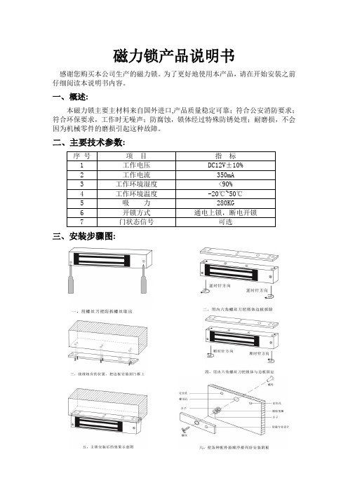
磁力锁产品说明书
感谢您购买本公司生产的磁力锁。
为了更好地使用本产品,请在开始安装之前仔细阅读本说明书内容。
一、概述:
本磁力锁主要主材料来自国外进口,产品质量稳定可靠;符合公安消防要求;符合环保要求,工作时无噪声;防腐蚀,锁体经过特殊防锈处理;耐磨损,不会因为机械零件的磨损引起这种故障。
二、主要技术参数:
序号项目指标
1 工作电压DC12V±10%
2 工作电流350mA
3 工作环境湿度<90%
4 工作环境温度-20℃~50℃
5 吸力280KG
6 开锁方式通电上锁,断电开锁
7 门状态信号可选
三、安装步骤图:
四、线路板示意图:
注:上图中接电源的插座只需接一个,带LED磁力锁才具有门状态信号
五、注意事项:
1.磁力吸板的螺丝不要上的太紧,要让橡胶垫圈保持适当的弹性,使磁力吸板吸力自动调整到正确的位置。
2.磁力吸板安装要与锁体对正,以免吸力不够。
3.磁力锁工作时会产生较强磁场,请勿将对磁敏感元件靠近锁体。
- 1、下载文档前请自行甄别文档内容的完整性,平台不提供额外的编辑、内容补充、找答案等附加服务。
- 2、"仅部分预览"的文档,不可在线预览部分如存在完整性等问题,可反馈申请退款(可完整预览的文档不适用该条件!)。
- 3、如文档侵犯您的权益,请联系客服反馈,我们会尽快为您处理(人工客服工作时间:9:00-18:30)。
磁力锁参数
磁力锁是一种常见的电子门锁,它是通过利用电磁力来控制门的
开关。
磁力锁有两个主要部分,一是电磁铁,二是电子控制系统。
在
实际应用中,磁力锁的参数包括了以下几个方面。
首先是电源电压。
磁力锁的电源电压一般为DC12V或DC24V,这
是为了保证磁铁能够正常工作。
在实际安装时,需要根据具体的情况
选择合适的电源电压。
其次是吸力。
吸力是指磁铁的吸牢力度。
磁力锁的吸力一般为
100kg、200kg、300kg等不同的等级。
选择吸力大小需要根据门的尺寸和用途来确定,以保证门的安全性。
再次是外形尺寸。
磁力锁的外形尺寸也是需要考虑的因素。
一般
来说,磁力锁的外形尺寸分为单框和双框两种,需要根据门框的大小
和形状来选择。
最后是防盗等级。
磁力锁的防盗等级也是非常重要的参数。
磁力
锁的防盗等级从低到高依次为A级、B级、C级、D级。
不同等级的磁
力锁能够提供不同程度的防盗保护,需要根据门的位置和需求来选择。
以上是关于磁力锁的几个主要参数的介绍。
在安装磁力锁时,需
要根据具体情况选择合适的参数,并严格按照说明书进行操作。
这样
可以保证磁力锁的正常使用,并且有效提高门的安全性。