联科智能电源管理器说明书V1803
智能调节器使用说明书

SIC-03型━━━━━━━━━━━━━━━━━组合型智能调节器智能调节器安装使用说明书━━━━━━━━━━━━━━━━━大连工业大学━━━━━━━━━━━━━━━━━大连工业大学一、概述一、概述本型号调节器是基于MCU(微型工业处理器)的新一代调节器,硬件设计上采用最新的微处理器技术及IC技术。
软件设计上采用成熟、可靠的控制算法,全部程序采用汇编语言实现,效率高、速度快。
显示功能完善:测量值、设定值、两参数在前面板同时以光柱和数码管两种形式显示,光柱用于以百分数形式显示两参数,数码管用于以工程量形式显示两参数;输出值以数字形式显示,阀位值以光柱形式显示,所有操作过程中关心的参数:测量值、设定值、输出值、阀位值、自动/手动控制方式、内/外给定方式、正/反作用方式在调节器的前面板上同时显示,不必按键选择显示,方便对控制过程的监控。
操作简单:仅通过前面板上四个按键,可实现对设定参数、实时参数的监测,其中,需要经常整定的PID参数、手动/自动切换操作,专门设计了简洁的操作方法,方便操作。
支持RS-485总线,有专门的通讯协议,方便构成现场总线测控系统。
二、主要功能与技术指标主要功能:1.自动/手动双向无平衡无扰动。
2.积分、微分作用可切除。
3.重要参数:被控变量给定值与测量值以数字形式与光柱形式同时显示;被控变量的工程量与满量程百分数同时显示;被控变量给定值、测量值、调节器输出值、阀位值、自动/手动状态、内/外给定形式、正/反作用方式同时在仪器的前面板上显示,不用任何操作,可完全了解调节器的工作情况。
4.支持RS-485通讯技术,方便构成局域控制网络。
5.当被控变量测量信号出现故障(小于2mA)时,阀位可保持在原有位置或自动切换到预置位置上。
主要技术指标:⒈输入信号⑴来自现场变送器的 4~20mA 电流信号或配电器输出的1~5V电压信号,两种信号可通过按键选择。
⑵外给定信号:4~20mA 电流信号。
⑶阀位信号:4~20mA 电流信号。
unit3 智能控制器说明书

unit3 智能控制器说明书
智能控制器是一种用于控制和管理各种设备和系统的装置。
它
通常具有自动化、智能化和远程控制的功能,能够实现对设备的精
确控制和监控。
智能控制器通常应用于工业自动化、建筑物管理系统、智能家居等领域。
下面我将从多个角度全面介绍智能控制器的
说明书内容。
首先,智能控制器说明书通常包括产品的基本信息,如型号、
规格、外观尺寸、工作原理等。
这些信息可以帮助用户了解产品的
基本特性和适用范围。
其次,说明书会详细介绍智能控制器的安装和操作步骤。
包括
安装环境要求、安装方法、接线方式、开机操作、参数设置等内容。
这些内容对用户正确使用和维护智能控制器至关重要。
另外,智能控制器说明书还会对产品的功能特点进行详细说明,包括各种传感器、执行器的连接方式、通讯协议、远程监控等功能。
用户可以通过说明书了解产品的功能优劣势,以便更好地应用和操作。
此外,说明书通常也会包括故障诊断与排除方法,以及维护保养等内容。
这些内容对于用户在日常使用中遇到问题时能够及时处理故障,保证设备的正常运行具有重要意义。
最后,智能控制器说明书还可能包括产品的技术参数、安全注意事项、售后服务政策等内容,以帮助用户更全面地了解产品并获取相关的支持和服务。
综上所述,智能控制器说明书是用户了解、安装、操作和维护智能控制器的重要参考资料,它的内容应该全面、详细、准确,以确保用户能够正确、安全地使用智能控制器,同时也为售后服务提供了重要的依据。
智能控制器使用手册

智能控制器使用说明书一概述智能控制器是框架式空气断路器的核心部件,适用于50~60Hz电网,主要用作配电、馈电或发电保护,使线路和电源设备免受过载、短路、接地/漏电、电流不平衡、过压、欠压、电压不平衡、过频、欠频、逆功率等故障的危害:通过负载监控,需量保护,区域连锁等功能实现电网的合理运行。
同时也用作电网节点的电流、电压、功率、频率、电能、需量、谐波等电网参量的测疑;故障、报警、操作、电流历史最大值、开关触头磨损情况等运行维护参数的记录;当电力网络进行通讯组网时,智能控制器可用为电力自动化网络的远程终端实现遥测,遥信,遥控,遥调等,智能控制器支持多种协议以适用不同的组网要求。
二基本功能2. 1. 3通讯功能通讯功能为可选项,对于M型没有通讯功能,对于H型通讯协议可根据需要选择为Modbus.Profibus-DP.Device net.2. 1. 4增选功能选择增选功能为可选项,M型,H型都可以选择增选功能配置,不同增选功能代号与增选功能内容如表2所示。
增选功能代号D V VD P PD H HD1. 需用值测址2. 需用值保护1 •电压测虽2. 频率测虽3. 电压不平衡率及保护4. 相序检测5. 过压保护6. 欠压保护7. 电压不平衡保护8. 过频保护9・欠频保护10.相序保护1 •电乐测虽2.频率测虽3 •电压不平衡率4.相序检测5 •电流需用值测址6. 过压保护7. 欠压保护8 •电乐不平衡保护9・过频保护10. 欠频保护11. 相序保护12. 需用值保护1 •电压测虽2.频率测虽3 •电乐不平衡率4・相序检测5. 功率测虽6. 功率1大]数测a7 •电能测虽8・过圧保护9・欠压保护10 •电压不平衡保护11.过频保护12・欠频保护13. 相序保护14. 逆功率保护1 •电压测虽2.频率测虽3 •电压不平衡率4. 相序检测5. 功率测虽6. 功率I大1数测a7 •电能测虽8・需用值测址9・过乐保护10.欠乐保护11•电压不平衡保护12. 过频保护13. 欠频保护14. 相序保护15. 逆功率保护16. 最大需用值保护[电压测量2・频率测址3. 电压不平衡率4. 相序检测5. 功率测址6. 功率因数测量7「电能测虽8・谐波测虽9・过压保护10.欠乐保护11•电压不平衡保护12. 过频保护13. 欠频保护14. 相序保护15・逆功率保护1 •电压测量2.频率测量3・电压不平衡4. 相序检测5. 功率测虽6. 功率因数测址7. 电能测虽8・需用值测fit9・谐波测量10. 过压保护11. 欠压保护12 •电压不平衡保护13. 过频保护14. 欠频保护15. 相序保护16. 逆功率保护17. 最大需用值保护表2增选功能配登表2. 1. 5区域连锁及信号单元的选择“区域连锁及信号单元”为可选项,M型、H型都可以选择信号单元的功能配豊,当信号单元选择为S2, S3 时,控制器具备区域连锁功能。
Excelsys CoolX1800高效智能可靠1800W模块电源说明书
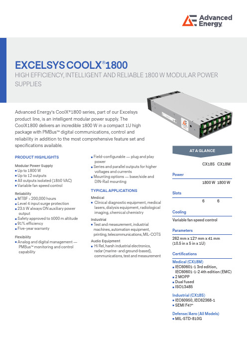
EXCELSYS COOLX ®1800HIGH EFFICIENCY, INTELLIGENT AND RELIABLE 1800 W MODULAR POWERSUPPLIESAdvanced Energy's CoolX®1800 series, part of our Excelsysproduct line, is an intelligent modular power supply. TheCoolX1800 delivers an incredible 1800 W in a compact 1U high package with PMBus™ digital communications, control andreliability in addition to the most comprehensive feature set and specifications available.CX18S CX18M Power1800 W 1800 WSlots66CoolingVariable fan speed control Parameters262 mm x 127 mm x 41 mm(10.5 in x 5 in x 1U) CertificationsMedical (CX18M)⏹ I EC60601-1 3rd edition,IEC60601-1-2 4th edition (EMC)⏹ 2 MOPP ⏹ D ual fused ⏹ I SO13485Industrial (CX18S)⏹ I EC60950, IEC62368-1⏹ S EMI F47*Defense/Aero (All Models)⏹ M IL-STD-810GAT A GLANCEPRODUCT HIGHLIGHTS Modular Power Supply ⏹ U p to 1800 W ⏹ U p to 12 outputs ⏹ A ll outputs isolated (1850 VAC)⏹ V ariable fan speed controlReliability ⏹ M TBF > 200,000 hours ⏹ L evel 4 input surge protection ⏹ 23.5 W always ON auxiliary power output ⏹ S afety approved to 5000 m altitude ⏹ 91% efficiency ⏹ F ive-year warrantyFlexibility ⏹ A nalog and digital management — PMBus™ monitoring and control capability⏹ F ield-configurable — plug and playpower⏹ S eries and parallel outputs for higher voltages and currents ⏹ M ounting options — base/side and DIN-Rail mountingTYPICAL APPLICATIONSMedical ⏹ C linical diagnostic equipment, medical lasers, dialysis equipment, radiological imaging, chemical chemistryIndustrial ⏹ T est and measurement, industrial machines, automation equipment,printing, telecommunications, MIL-COTS Audio Equipment ⏹ H i Rel, harsh industrial electronics, radar (marine- and ground-based),communications, test and measurementCOOLX1800 SERIES1Full dynamic specifications may not be met at full load when output voltage is trimmed above 13 V.2Max Trim 14 V when used with High Power Module3Max Trim 56 V when used with High Power Module4 a) Only one High Power module (CmE or CmF) can be used per CoolPac.b) During load transients starting from 0% load on the High Power modules, other modules in the CoolPac may experience an output voltage dynamic during the load change. Contact applications support for details or support..5For the CmG module the max combined power of both outputs is 200 W.6 For the CmH module the max combined power of both outputs is 180 W.*SEMI F47 compliant at input voltages > 180 VAC. Consult Advanced Energy for details.2 COOLX1800 SERIES 3COOLX1800 SERIESELECTRICAL SPECIFICATIONS (CONTINUED)4 COOLX1800 SERIES1Consult AE applications for system level compliance 5COOLX1800 SERIES6 COOLX1800 SERIESMechanical Drawings11Standard airflow direction* Maximum screw penetration from base does not exceed 1.5mm. 78 COOLX1800 SERIES 9COOLX1800 SERIESInput ConnectorsCoolPac ConnectorsStandard (Screw Terminal)Option 1 (IEC Terminal)10 COOLX1800 SERIESCoolMod ConnectorsCOOLX1800 SERIES*CmE or CmF High Power Module (3 slot module) can only occupy Slots D/E/F.Configuration Example 1CoolX part number CX18S-ADG##E-N-A specifies the following product;• CX18S 1800W IEC60950 approved• Slot 1: CmA: 2.5-6.0V (150W)• Slot 2: CmD: 28-58V (300W)• Slot 3: CmG: Dual output 3-30V (120 per channel)• Slot 4: Not Available (CmE is three slot CoolMod module)• Slot 5: Not Available (CmE is three slot CoolMod module)• Slot 6: CmE: 22.8-25.2 (900W)• Option N: Nominal Output voltage settings• Option A: 12V/(1.96)A Bias Supply VoltageConfiguration Example 2CoolX part number CX18M-BABBDC-N-B specifies the following product;• CX18M 1800W IEC60601-1 approved• Slot 1: CmB: 6-15V (280W)• Slot 2: CmA: 2.5-6.0V (150W)• Slot 3: CmB: 6-15V (280W)• Slot 4: CmB: 6-15V (280W)• Slot 5: CmD: 28-58V (300W)• Slot 6: CmC: 15-28V (300W)• Option N: Nominal Output voltage setting• Option B: 5V/(4.7A) Nominal Output voltage setting 11ABOUT ADVANCED ENERGYAdvanced Energy (AE) has devoted more than three decades to perfecting power for its global customers. AE designs and manufactures highly engineered, precision power conversion, measurement and control solutions for mission-critical appli-cations and processes.AE’s power solutions enable customer innovation in complex semiconductor and industrial thin film plasma manufacturing processes, demanding high and low voltage applications, and temperature-critical thermal processes.With deep applications know-how and responsive service and support across the globe, AE builds collaborative partnerships to meet rapid technological developments, propel growth for its customers and power the future of technology.Specifications are subject to change without notice. Not responsible for errors or omissions. ©2021 Advanced Energy Industries, Inc. All rights reserved.Advanced Energy® and AE® are U.S. trademarks, and CoolX® is a U.S. and Europe trademark of Advanced Energy Industries, Inc.For international contact information,visit advancedenergy .com ENG-LV-COOLX1800-235-15 07.21。
智能低压无功补偿控制器使用说明书
目录一.产品概述 (1)二.功能特点 (1)三.使用环境 (2)四.技术参数 (2)五.安装与接线 (2)六.操作与运行 (5)七.系统调试 (12)八.常见现象分析 (14)九.售后服务 (15)一.产品概述智能无功补偿控制器(以下简称控制器)是本公司在吸收了国内外多个无功自动补偿控制器技术的基础上研发出来的新一代产品,款式新,功能全,安装使用灵活,全中文液晶菜单,操作方便。
控制器具有RS-485通讯接口,与本公司生产的智能低压电力电容器配套使用,接线简洁,运行可靠。
二.功能特点1.参数设置功能1)过压值、欠压值、欠流值等保护定值的设置;2)延时时间、投入、切除门限等投切限值的设置;3)取样电流互感器变比的设置。
2.测量功能1)取样互感器极性自动判别,接入时无需考虑极性要求;2)配电电压、电流、功率因数、有功功率、无功功率测量。
3.控制功能1)自动、手动控制电容器的投切。
自动控制时,根据受控物理量-无功功率进行投切;2)容量相同的电容器按循坏投切方式工作,容量不同的电容器按无功缺额进行编码投切;3)最多可同时控制32台智能低压电力电容器。
4.保护功能配电系统过电压保护、过电压闭锁、欠电压保护、欠流保护、缺相保护。
5.信号功能1)各台电容器投运、退运状态信号显示,各台电容器容量信号显示,各台电容器温度信号显示;2)配电参数越限信号(过压、欠压等)显示;3)控制器本身或电容器故障显示。
三. 使用环境工作温度: -20℃-60℃ 相对湿度: ≤90%(20℃) 大气压力: 79.5-106.5kpa 海拔高度: ≤3000m无易燃易爆的介质存在,无导电尘埃及腐蚀性气体存在。
四. 技术参数额定电压: 交流50Hz ,380V ±20% 电流取样: ≤5A 额定频率: 50Hz ±5% 净重:约0.8kg五. 安装与接线1.安装在屏柜上开113*113mm 的方孔,将本产品从屏前推入方孔内,把配给的紧固件插入安装槽中,上紧即可固定在屏上。
ктек 专业电池管理器说明书

E NGENERATE EXPLOSIVE GASES DURING NORMAL BATTERY OPERATION. FOR THIS REASON, IT IS OF UTMOST IMPORTANCE THAT, YOU FOLLOW THE INSTRUCTIONS EACH TIME YOU INSTALL THE CHARGER.b) To reduce risk of battery explosion, follow these instruc-tions and those published by the battery manufacturerand the manufacturer of any equipment you intend to use in vicinity of battery. Review cautionary marking on these products and on engine.c) Disconnect battery poles before installationd) D250S DUAL is not reverse polarity protected.11. PERSONAL PRECAUTIONSa) Consider having someone close enough by to come toyour aid when you work near a lead-acid battery.b) Have plenty of fresh water and soap nearby in case bat-tery acid contacts skin, clothing or eyes.c) Wear complete eye protection and clothing protection.Avoid touching eyes while working near battery.d) If battery acid contacts skin or clothing, wash immediatelywith soap and water. If acid enters eye, immediately flood eye with running cold water for at least 10 minutes andget medical attention immediately.e) NEVER smoke or allow a spark or flame in vicinity of bat-tery or engine.f) Be extra cautious to reduce risk of dropping a metal toolonto battery. It might spark or short-circuit battery or other electrical part that may cause explosion.g) Remove personal metal items such as rings, bracelets,necklaces, and watches when working with lead-acidbattery. A lead-acid battery can produce a short-circuitcurrent high enough to weld a ring or the like to metal,causing a severe burn.h) Use charger for charging a LEAD-ACID battery only. Donot use battery charger for charging dry-cell batteries that are commonly used with home appliances. These batter-ies may burst and cause injury to persons and damage to property.i) Never charge a frozen battery.12. PREPARING TO CHARGEa) If necessary to remove battery from vehicle to charge,always remove grounded terminal from battery first. Make sure all accessories in the vehicle are off, so as not tocause an arc.b) Be sure area around battery is well ventilated while bat-tery is being charged.c) Clean battery terminals. Be careful to keep corrosion fromcoming in contact with eyes.d) Add distilled water in each cell until battery acid reacheslevel specified by battery manufacturer. Do not overfill.For a battery without removable cell caps, such as valveregulated lead acid batteries, carefully follow manufac-turer’s recharging instruction.e) Study all battery manufacturer’s specific precautions whilecharging and recommended rates of charge.f) Determine voltage of battery by referring to vehiclesmanual.13. CHARGER LOCATIONa) Never place charger directly above battery beingcharged; gases from battery will corrode and damagecharger.b) Never allow battery acid to drip on charger when read-ing electrolyte specific gravity or filling battery.c) Do not set a battery on top of charger.14. FOLLOW THESE STEPS WHEN BATTERY IS INSTALLED IN VEHICLE. A SPARK NEARBATTERY MAY CAUSE BATTERY EXPLOSION. TO REDUCE RISK OF A SPARK NEAR BATTERY:a) Position cords to reduce risk of damage by hood, door ormoving engine part.b) Stay clear of fan blades, belts, pulleys, and other partsthat can cause injury to persons.c) Check polarity of battery posts. POSITIVE (POS, P, +)battery post usually has larger diameter than NEGATIVE (NEG, N, -) post.d) Determine which post of battery is grounded (connected)to the chassis. If negative post is grounded to the chassis (as in most vehicles) see (e). The battery charger can not be used with positive-grounded batteries.e) For Negative-grounded vehicle, connect POSITIVE con-nector from battery charger to POSITIVE (POS, P, +)ungrounded post of battery. Connect NEGATIVE connec-tor from battery charger to vehicle chassis or engine block away from battery. Do not connect to carburetor, fuellines, or sheet-metal body parts. Connect to a heavy gage metal part of the frame or engine block.f) When disconnecting charger, always do so in reversesequence of connecting procedure and break first connec-tion while as far away from battery as practical.15. FOLLOW THESE STEPS WHEN BATTERY IS OUTSIDE VEHICLE.A SPARK NEAR BATTERY MAY CAUSE BATTERY EXPLOSION. TO REDUCE RISK OFA SPARK NEAR BATTERY:a) Check polarity of battery terminals. POSITIVE (POS,P, +) battery post usually has a larger diameter thanNEGATIVE (NEG, N, -) post.b) Attach at least a 24-inch-long 6-gauge (AWG) insulatedbattery cable to NEGATIVE (NEG, N, —) battery post. c) Connect POSITIVE charger connector to POSITIVE (POS,P, +) post of battery.d) Position yourself and free end of cable as far away frombattery as possible – then connect NEGATIVE chargerconnector to NEGATIVE (NEG, N, -) post of battery.e) Do not face battery when making the final connection.f) When disconnecting charger, always do so in reversesequence of connecting procedure and break first connec-tion while as far away from battery as practical.SAFETY• D250S Dual and SMARTPASS is designed for 12V lead-acid batteries. Do not use the unit for any other batteries.• Disconnect battery poles before installation• D250S Dual is not sprak proof.• The installation must include a fuse according to recommen-dations in table “CABLE DIMENSIONS”.All installations on boats must follow ISO 10133. Please note!1. Connections from the battery must be fused close to the battery.2. Batteries must be permanently mounted in ventilated areas.3. Cables must be placed in tubes, separated from cables for 110/230 V (shore power), or be attach to the surface every 300 mm.4. Cables in the engine room must be rated to withstand 70°C/158°F5. For a permanently connencet battery charger: GROUNDING INSTRUCTIONS— This battery charger should be connected to a grounded, metal, permanentE Nwiring system; or an equipment-grounded conductor should be run with circuit conductors and connected to equipment-grounded terminal or lead on battery charger. Connections to battery charger should comply with all local codes and ordinances.D250S DUALThe D250S Dual has 2 inputs. The Service battery will be charged from the alternator, solar panel, or both in combina-tion. The solar panel adjusts itself to the Starter battery voltage. The Starter battery will be charged and maintained directly by the solar panel if the Service battery is fully charged.D250S DUALFEATURES:• Multi-step 20 A temperature compensated battery charging and battery maintenance.• Battery separation of Starter and Service batteries.• Maximum power point tracking for solar panels charging the Service battery.• Two power source inputs (alternator, solar, wind, Supply battery and other).• Coordination of the two inputs, allowing parallel operation. • The solar input will also maintain the Alternator battery.• Built in battery guard for the Alternator battery.battery +battery +Vehicle ground/E NSMARTPASSSMARTPASS can operate as a stand-alone unit, but works best in combination with D250S Dual. The SMARTPASS createsa priority path for charging the Service battery to rechargeit more quickly and efficiently. Attached energy sources like solar, wind or shore power will charge both the Service and the Starter batteries through the SMARTPASS. Service batteries that are overheated due to age, high ambient temperature or other battery problems will be protected from high alternator current.SMARTPASSFEATURES:The CTEK SMARTPASS adds additional functionality for higher output alternators, larger battery banks and/or high parallel loads.• Separation of consumers and Service batteries during charging, which improves the charging capacity signifi-cantly, and lowers the consumer voltage, which increases expected service life of lights and other electronics.• Service battery watch, which avoids harmful deep dis-charges that otherwise would shorten battery life. The bat-tery watch also protects navigation, radio and emergency light from being out of electricity.• Over-temperature protection of Service battery. High bat-tery temperature could significantly reduce battery life.• Maintenance charge of Starter battery, which simplifies installation with fewer components.• Simplified installation of AC/DC chargers (shore power). Only one output from the AC/DC charger needed.The CTEK SMARTPASS is designed to work together with 1-2 CTEK D250S DUAL, but can also be used alone.Negative cable Alternator ServiceE NINSTALLATION OF UNIT1. Attach the temperature sensor holder on a flat surface onone Service battery. Position it as close as possible to apositive post.2. Use the included drill template. Wiring is simplified if theunits are installed according to the drill template, but other setups are possible.3. Install the unit(s) on a surface where it can be properlyfixed and where the unit is not exposed to fuels, oils orsplashes of dirt.4. Mount the unit with screws intended for the surface andattach it with one screw in each of the four holes in thecorners of the unit. See picture 1. Mount the unit with M4 or ST4.2 screws. The required torque depends on the sur-face for mounting. Fig. 1 shows a CTEK D250S. The same procedure is used for all devices.5. Attach the cables and mount the cable screws with atorque of 7 Nm/62 Lb-In. Use tool – hand power without tools is not enough.6. The ground cable of the SMARTPASS should be connect-ed to the ground screw of the DUAL or to any convinientground connection point.INSTALLATION OF CABLESFigure 1Figure 22Nm/18 Lb-In7Nm/62 Lb-InAllen keyWARNING!D250S DUAL andSMARTPASS is not reversepolarity protected.Disconnect battery polesbefore installation.WARNING!D250S DUAL is not sparkproof. Provide for goodventilation.E NE NE NE NNE EN • 23E N26 • EN2012–05–3020020400ATEMPERATURE PROTECTION SMARTPASS has a temperature sensor cable. The units willautomatically protect the service battery if the temperatureand charging voltage together are too high. Charging will thenonly be performed by the D250S battery charger. The temper-ature should be measured close to the battery, therefore attach the sensor to the battery.LIMITED wARRANTYCTEK SWEDEN AB, issues this limited warranty to the original purchaser of this product. This limited warranty is not trans-ferable. The warranty applies to manufacturing faults and material defects for 2 years from the date of purchase. The customer must return the product together with the purchase receipt. This warranty is void if the battery charger has been opened, handled carelessly or repaired by anyone other than CTEK SWEDEN AB or its authorised representatives. One of the screw holes in the bottom of the charger is sealed. Removing or damaging the seal will void the warranty.CTEK SWEDEN AB makes no warranty other than this limited warranty and is not liable for any costs other than those men-tioned above. For example, consequential damages are not covered. Moreover, CTEK SWEDEN AB is not obligated to any other warranty other than this warranty.CTEK PRODUCTS AREFor latest revised user manual and CTEKs professional customer support: (EU), (US).Bye-mail:************(EU),***********************(US).By telephone: +46(0) 225 351 80 (EU), (330) 963-0981 (US).。
智能控制器使用手册

一概述智能控制器是框架式空气断路器的核心部件,适用于50~60Hz电网,主要用作配电、馈电或发电保护,使线路和电源设备免受过载、短路、接地/漏电、电流不平衡、过压、欠压、电压不平衡、过频、欠频、逆功率等故障的危害;通过负载监控,需量保护,区域连锁等功能实现电网的合理运行。
同时也用作电网节点的电流、电压、功率、频率、电能、需量、谐波等电网参量的测量;故障、报警、操作、电流历史最大值、开关触头磨损情况等运行维护参数的记录;当电力网络进行通讯组网时,智能控制器可用为电力自动化网络的远程终端实现遥测,遥信,遥控,遥调等,智能控制器支持多种协议以适用不同的组网要求。
二基本功能对于M型无任何可选功能(加*的项目)时其功能配置为基本功能,如表1所示:表1 基本功能配置2.1.3 通讯功能通讯功能为可选项,对于M型没有通讯功能,对于H型通讯协议可根据需要选择为Modbus,Profibus-DP,Device net.2.1.4增选功能选择增选功能为可选项,M型,H型都可以选择增选功能配置,不同增选功能代号与增选功能内容如表2所示。
表2 增选功能配置表2.1.5 区域连锁及信号单元的选择“区域连锁及信号单元”为可选项,M型、H型都可以选择信号单元的功能配置,当信号单元选择为S2,S3时,控制器具备区域连锁功能。
2.2 技术性能2.2.1 适用环境工作温度:-10℃~+70℃(24h•内平均值不超过+35℃)储存温度:-25℃~+85℃安装地点最湿月的月平均最大相对湿度不超过90%,同时该月的月平均最低温度不超过+25℃,允许由于温度变化产生在产品表面的凝露。
污染等级:3级。
(在和断路器装配在一起的情况下)安装类别:Ⅲ。
(在和断路器装配在一起的情况下)2.2.2工作电源由辅助电源和电源互感器同时供电,保证负载很小和短路情况下控制都可以可靠工作。
控制器的供电方式有下面3种方式:a.电源CT供电额定电流大于等于400A时,一次电流单相不低于0.4In,三相不低于0.2In时控制器正常工作。
智能充电器使用说明书
WM-S2425C系列智能型充电器使用说明书
一:功能简介
WM-2460C系列充电器是目前一款比较先进的智能型蓄电池充电器,它一改传统充电器的充电模式。
自行研发的蓄电池充电管理功能,具有优化的充放电曲线。
充电时、只要接好蓄电池和充电器插件,开通电源,本机可自动检测待充蓄电池现存电量和环境温度,根据待充蓄电池不同的放电量和实时的环境温度进行充电,蓄电池充足后自动关闭充电系统。
二:应用范围
本系列充电器广泛应用于剪叉式升降平台、电瓶车、电动叉车、电动汽车、电动摩托车、电动洗地车、电动船、电动观光车、电动巡逻车、电动高尔夫球车、电动牵引车、电动残疾车、电动代步车、电动医疗设备、电动搬运车等各类电动车的铅酸免维护蓄电池、铅酸加水蓄电池、铅酸胶体蓄电池循环充电。
三:技术参数
1;输入电压AC185V-265V 47Hz-~63Hz
2:最大功耗0.75Kw
3:输出电压出厂时内部软件设定(28.8V在线式)
4;输出电流25A
5:充电时间蓄电池放电80%时,全程充电6-11小时
6;体积344×177×81 (L×W×H)
7:重量 3.6Kg
8:EMC EMI LVD符合欧洲CE 标准
9: 环境温度-40℃to +55℃
10: 湿度< 95%
11: 安全等级1(IEC364-4-41)
12:防护等级IP65
三:警告!
1、使用和安装充电器之前请仔细阅读说明书。
2、机内有相当于电网量的同等电压,非专业人员不得带电拆机
3、充电电器应该安装在一个干燥、清洁的环境中,以防潮湿和尘污;
4、充电器只能与相对应容量的电池充电,否则会产生危险或重大事故。
- 1、下载文档前请自行甄别文档内容的完整性,平台不提供额外的编辑、内容补充、找答案等附加服务。
- 2、"仅部分预览"的文档,不可在线预览部分如存在完整性等问题,可反馈申请退款(可完整预览的文档不适用该条件!)。
- 3、如文档侵犯您的权益,请联系客服反馈,我们会尽快为您处理(人工客服工作时间:9:00-18:30)。
.. ..
. . . .
产 品 手 册
LKU-136-50
智能电源管理器
.. ..
. . . .
目录
1. 主要功能 ....................... 3
1.1 辅助电源功能 ............... 3
1.2 电源检测功能 ............... 3
1.3 电源控制功能 ............... 3
1.4 功能框图 ................... 3
2. 技术指标 ........................ 4
3.安装说明 ......................... 4
3.1 设备正反面示意图 .......... 4
3.2 接线端子说明: ............ 5
3.3 接线示意图 ................. 5
4.方案功能描述 ..................... 5
.. ..
. . . .
1. 主要功能
1.1 辅助电源功能
提供 DC12V/2A 辅助电源输出。可用于报警控制器或报
警主机断电后的正常工作。在断电之后,能够提供+12V
电源持续续航的能力。
1.2 电源检测功能
检测 AC220V 电源断电/来电,或开关状态发生变化时,
输出开关信号可实现断电报警功能。
1.3 电源控制功能
检测 AC220V 电源断电/来电,或开关状态发生变化时,
向本地服务器推送告警。
1.4 功能框图
电池
容量指示灯
断电侦测1UPS输入市电输入12V输出稳压器 断电
侦测2
断电报警输出1断电
报警
输出2
锂电池
充电器
开关量输出1开关
量
输出2
.. ..
. . . .
2. 技术指标
输入信号 电源
可接入检测信号 2类 工作电源输入 AC220V*0.3A
信号 1 类型 AC220V 辅助电源输出 DC12V*2A
信号 2 类型 开关量 上电/断电报警监测
输出端口 外形尺寸
继电器输出 4*3 主机机箱 440 x 362 x 44.5
工作环境条件
工作温度 -20℃到 50℃ 工作湿度 不大于 90%,非凝露
3.安装说明
3.1 设备正反面示意图
设备正面
设备背面
.. ..
. . . .
3.2 接线端子说明:
UPS 电源输入:AC220V 输入,为本机提供正常工作
电源;
市电检测输入:市电 AC220V 输入,用于断电/来电
检测报警;
IN1,IN1_RTN:开关信号输入1,用于开关信号状态
转换;
IN2,IN2_RTN:开关信号输入2,用于开关信号状态
转换;
+12V,GND:12V稳压电源输出,3路输出分别可以在
UPS输出断电后延时输出2小时,8小时,48小时;
NO、COM、NC开关量输出接口。
3.3 接线示意图
4.方案功能描述
备用电源系统
12V直流稳压电源输出:
通道1视频持续供电时间不低于2小时;
通道2报警设备不低于8小时;
通道3门禁设备不低于48小时;
.. ..
. . . .
以上后备时间均为单独通道供电时间,三通道同时供电
时间会有所减少。
断电/上电检测报警系统:检测市电 AC220V 和UPS
电源断电/来电,或开关状态发生变化时,输出开关
信号并延时。可接入报警控制器实现断电报警功能,
通过报警主机处理并传送至监控中心和管理人员。
电池电量监控系统:监控并本地显示电池当前电量百
分比。
辅助电源功能:提供 DC12V/50AH 辅助电压输出。可
用于报警控制器或联动箱等设备断电后的正常工作。
信号状态转换功能:开关状态发生变化时,输出开关
信号与输入信号状态相反。
无线报警系统:报警信号通过 GSM 模块(或 GPRS
模块)传送至监控中心接警机和管理人员手机
(AC220V 电源断电后仍能正常传输报警信息)。
有线报警系统:报警信号通过外接有线网络或线传送
至监控中心管理平台。
电源远程控制系统:远程监控中心可以根据前端设备
供电负载情况进行开关操作。
.. ..
. . . .
用户须知
本安装使用手册适用于购买LKU-136-50电源管理控制箱
或首次安装及使用过其它类似产品的安装工程人员。
请通过专业技术人员及经过培训的工程人员安装此设
备!必须严格参照此手册中描述的方法进行正确的安
装、操作使用与日常维护,不正确的安装和接线不仅会
造成设备不能正常工作,甚至可能导致本机部电路损
坏。
免责声明
本手册没有任何形式的担保及承诺。若因本手册或者是
所提及的产品信息和功能,所引起的直接或间接的利益
损失或事业终止,或者涉及国家相关标准符合性问题引
起的法律风险,或者是因对本手册容理解上的偏差和任
何安装使用不当造成的直接、间接、有意、无意损坏及
隐患,本公司恕不为其担负任何责任。
本手册可能包含技术上不准确的地方或印刷错误。我们
将会随时改进或更新本手册中所描述的产品,本手册的
容也将做定期的版本更新,恕不另行通知,更新的容将
会在本手册的新版本中加入。
.. ..
. . . .
联系技术支持
请您在联系技术支持之前,确认已做了下面工作:
1) 仔细阅读本产品手册检查所有的连线检测电源或后
备电池供电是否正常检测各保险丝管是否熔断
2) 留意您的公司名称及有效的通信联络方式
您可以通过下述联系方式与我们的技术支持联系,您将
在 24 小时得到答复。
客户服务支持中心信息
制造单位:联科众能科技股份
地 址:市光明新区大岗路腾鸿兴科技园2栋7楼
邮 编:518107
技术支持:400 1688 008
传 真:08
.. ..
. . . .
安全性须知电气方面的安全性
本机有交流 220V 高电压接入,为避免可能的电击造成
严重损害,在安装或维护本机时,请先将本机引入的交
流 220V 电源切断。
当您将 220V 交流电源线接入本机的接线端子时,应保
证不要将电线的金属部分裸露出接线端子,更不能出现
电线的金属部分触碰或存在可能触碰机箱壳体的可能。
应将本机标识有接地符号的端子按照要求进行可靠的接
地处理。
必须严格参照说明书进行安装连线,不正确的安装和接
线不仅会造成设备不能正常工作,甚至可能导致设备部
电路损坏。
操作方面的安全性
请通过专业技术人员安装此设备!在您准备通电以前,
请务必详细阅读本手册所提供的相关信息。由于运输等
不可预知的原因,可能会造成设备硬件松动及脱落,在
安装本产品以前,请先打开机箱检查有无部件松动及脱
落;如果是您不能解决的任何重大瑕疵,请联络您的经
销商或直接与我们联系。
若在使用上有任何技术性问题,请和经过鉴定或有经验
的技术人员联络。灰尘、湿气及剧烈的温度变化都会影
响设备的使用寿命,请尽量避免放置在这些地方。请尽
.. ..
. . . .
可能把设备安装在较隐蔽或者受探测器、摄像机保护的
地方。
.. ..
. . . .
安装员须知
为确保系统长期稳定可靠地工作,系统需要安装工程师
或用户进行定期的维护及检测 (至少每年一次),而至关
重要的做法是定期进行各种功能测试(至少每周一
次),这样做才有可能确保系统时刻都能正常有效地工
作。
安装技术人员有责任培训操作人员熟悉系统运转及操
作。还应该将系统组成、常见问题处理以及系统的一些
局限性详细地告知用户,并让用户熟练掌握如何进行周
期性功能测试。
物件清单
请及时检查随机清单,若发现缺失或损坏,请及时联系
供应商。
主机
电源线 2 根
接线端子
安装使用手册 1 本
.. ..
. . . .
合格证
产品名称: 智能电源管理器
产品型号: LKU-136-50
本产品经出厂检验,合格。
联科众能科技股份
.lenkee.