Analysis of an unusual McPherson suspension failure
海利斯威尔 i30 N TCR 赛车说明书

Hyundai i30 N TCR means racingi30 N TCR championship wins2018 WTCR - FIA World Touring Car Cup (Driver and Team) 2019 WTCR – FIA World Touring Car Cup (Driver)2018 TC America (Team and Manufacturer)2018 TCR Korea (Driver, Team and Manufacturer)2019 TCR Europe (Driver and Team)2019 TCR Asia (Driver and Team)2019 TCR Australia (Driver and Team)2019 TCR Germany (Driver and Team)2019 TCR Russia (Driver and Team)2019 TCR Malaysia (Driver and Team)2020 TCR Germany (Driver and Team)2020 TCR Eastern Europe (Driver and Team)2020 TCR Malaysia (Driver and Team)2020 TCR UK (Driver and Team)2021 TCR UK (Driver and Team)2021 TCR Italy (Driver and Team)2021 TCR Germany (Driver and Team)Meetour first high-performance carfor circuit racingDesigned and developed by Hyundai Motorsport Customer Racing, the Hyundai i30 N TCR has been put through its paces in an extensive testing programme on circuits across Europe. Since April 2017, it has clocked up thousands of kilometres with lead test driver and former touring car champion Gabriele Tarquini at the wheel. Built to the increasingly popular TCR specifications and honed on specialist racetracks, it is eligible for a growing number of touring car and endurance categories around the world.Powerin drivers’ handsThe Hyundai i30 N TCR allows drivers to step in and immediatelyharness the full 350hp available at the wheels. A 2-litre turboengine helps lead the charge on track by delivering power directlycontrolled at the fingertips through a 6-speed paddle shiftsequential gearbox.All this wrapped in a striking, aerodynamic shell, the i30 N TCR has acommanding track presence aided by its high-downforce rear wing.The result is an agile car that responds instantly.This is a true high-performance machine. Thei30 N TCR is very impressive and rewarding todrive. Behind the wheel, you are instantly awarethat the i30 N TCR has many features normallyassociated with more technically-sophisticatedand costly touring car categories.- Gabriele Tarquini,2018 WTCR ChampionUnleashthe potential• Transverse mounted, 2-litre turbochargedengine with direct injection, intercooled• Life Racing ECU and data acquisition system• Pneumatic paddle shift operated, 6-speed• sequential gearbox with external preloadadjustment• Multi-disc motorsport clutch• Motorsport-specification driveshafts• Bespoke Brembo 6-piston monobloc caliperswith Ø380mm ventilated brake discs,• rear 2-piston monobloc calipers with Ø278mmventilated brake discs• Adjustable pedal box with spherical• bearing-mounted Brembo master cylinders• Goodridge braided hoses and fittings• Hydraulic steering rack• Front McPherson struts• Rear 4-arm multi-link• Adjustable dampers• Braid i30 N TCR-specific 10”x18” rims Protect and performEngine Transmission BrakingSteering SuspensionWheels Chassis• Hyundai Motorsport-designedlightweight high-tensile steel roll cage• Strengthened production body shell,painted-white interior and exterior• Body panels from steel and GFC• Race seats and 6-point HANS compatibleharnesses• 330mm flat steering wheel• Lifeline fire extinguisher system• 100-litre fuel tank with endurancerefuelling capability• Odyssey PC680 lightweight race battery• Length: 4,450mm• Width: 1,950mm• Wheel base: 2,650mm• Track width: 1,700mm• Minimum weight: 1,285kg (includingdriver, complying with TCR regulations) Specifications subject to changeInteriorDimensionsChooseto add moreCustomise any i30 N TCR with additional parts and services to suit more specific race applications. Options can include: Endurance kit (ABS, additional front lighting, externalrefuel kit) TCR scrutineering kitLife Racing analysis softwareAir jack connector and safety standsFuel refill kitToolingTrackside engineering support**available on request, fees may applySelectservices and on-event supportEvery Hyundai i30 N TCR is delivered fully assembled, ‘ready to race’ and with white-painted interior and exterior.A handover pack is provided with each car to help get up to speed. Each contains:Roll cage certificateFuel cell certificateCatalytic converter certificateUser manual (PDF version)Spare parts catalogue (PDF version)Hyundai Motorsport offers the following additional services: Trackside engineering support*On-event parts truck**Commercial termsIn addition to a signed purchase agreement, a deposit of €15,000 is required to confirm an order, with theremainder to be cleared prior to collection.Lead times will be confirmed at point of order with initial deliveries from December 2017.All sales are Ex-Works.*available on request, fees may apply**at selected eventsSpecifications subject to changeWantto find out more?To discuss the Hyundai i30 N TCR further or to arrange a viewing, please contact us:***********************#HMSGOfficial。
推荐 毕业设计红旗世纪星轿车悬架设计毕业论文 精品
摘要随着汽车工业的发展,人们对汽车的乘坐舒适性和安全性的要求逐渐提高,而悬架对汽车这一方面性能有很大的影响。
因此对汽车的悬架系统和减振器也提出了更高的要求。
本次设计主要内容是:红旗世纪星轿车的前、后悬架系统的结构设计,根据当前轿车悬架的发展情况,本设计的轿车前后悬架均采用独立悬架的形式,并且前后悬均采用比较流行的麦弗逊悬架。
根据确定的结构选取悬架的自振频率,从而可以计算出悬架的刚度、静挠度和动挠度。
采用以上数据计算弹性元件尺寸并且进行应力校核。
在设计减振器时,根据阻尼系数和最大卸荷力来计算选取减振器的主要尺寸。
然后再依次确定导向机构和横向稳定杆。
在所有结构尺寸确定后采用CAXA软件绘制前后悬架的装配图和零件图。
利用Matlab软件对悬架系统的平顺性进行了编程分析, 论证了该系统设计方案的合理正确性,能够满足实际的需要。
关键词:悬架;汽车减振器;平顺性;导向机构AbstractWith the development of the Automobile industry, people have been promoting the requirement for the safety and ride comfort quality of the vehicle. and suspension system influence this aspect of performance a lot. As a result, there is a higher demand on the suspension and the shock absorber system of the vehicle. while the car's suspension system also made high demands.The project mainly includes the design of construction of HongQi front and rear suspension system.Based on the current developments in the car suspension, the design of the car before and after the suspension are used in the form of independent suspension. Before and after the hanging and are used more popular McPherson suspension. According to determine the structure of the selected suspension natural frequency, which can calculate the stiffness of the suspension, static and dynamic deflection deflection. More flexible use of data of components and size of a stress check. In the design of shock absorber, in accordance with the largest damping and unloading of the terms of the main shock absorber selected size. Then bodies were identified and horizontal orientation Wending Gan. when all structure size are determined, using CAXA mapping software in before and after the suspension of the assembly and parts plans.Matlab software programming analysis was used in the ride suspension system.,demonstration of the system design of reasonable accuracy, to meet the actual needs.Key words: Suspension;Automobile shock absorber; Ride comfort ; Guide mechnism目录第1章绪论 (1)1.1 悬架简介 (1)1.2设计要求: (1)第2章前、后悬架结构的选择 (3)2.1独立悬架结构特点 (3)2.2独立悬架结构形式及评价指标分析 (3)2.3前后悬架结构方案 (4)2.4辅助元件 (5)2.4.1横向稳定杆图 (5)2.4.2导向机构 (6)第3章技术参数确定与计算 (7)3.1自振频率 (7)3.2悬架刚度 (7)3.3悬架静挠度 (7)3.4悬架动挠度 (8)3.5悬架弹性特性曲线 (8)第4章弹性元件的设计计算 (9)4.1前悬架弹簧 (9)4.1.1弹簧中径、钢丝直径、及结构形式 (9)4.1.2 弹簧圈数 (9)4.1.3 簧完全并紧时的高度 (9)4.1.4 应力校核 (10)4.2后悬架弹簧 (10)4.2.1弹簧中径、钢丝直径、及结构形式 (10)4.2.2 弹簧圈数 (10)4.2.3弹簧完全并紧时的高度 (11)4.2.4应力校核 (11)第5章悬架导向机构的设计 (12)5.1导向机构设计要求 (12)5.2麦弗逊独立悬架示意图 (12)5.3导向机构受力分析 (13)5.4横臂轴线布置方式 (14)5.5导向机构的布置参数 (14)5.5.1 侧倾中心 (14)5.5.2纵倾中心 (15)5.5.3抗制动纵倾性(抗制动前俯角) (16)5.5.4抗驱动纵倾性(抗驱动后仰角) (17)5.5.5悬架横臂的定位角 (17)第6章减振器设计 (18)6.1减振器概述 (18)6.2减振器分类 (18)6.3减振器主要性能参数 (19)6.3.1相对阻尼系数 (19)6.3.2减振器阻尼系数 (20)6.4最大卸荷力 (21)6.5筒式减振器主要尺寸 (21)6.5.1筒式减振器工作直径 (21)6.5.2油筒直径 (22)第7章横向稳定杆设计 (23)第8章平顺性分析 (25)8.1平顺性概念 (25)8.2 1/4汽车振动系统模型 (25)8.3车身加速度的幅频特性 (27)8.4相对动载的幅频特性 (28)8.5悬架动挠度的幅频特性 (29)8.6影响平顺性的因素 (30)8.6.1结构参数对平顺性的影响 (30)8.6.2使用因素对平顺性的影响 (30)第9章结论 (31)参考文献 (32)致谢 (33)附录Ⅰ (34)附录II (44)第1章绪论1.1悬架简介悬架是汽车的车架(或承载式车身)与车桥(或车轮)之间的一切传力连接装置的总称。
基于Adams的某商务车前悬架KC性能分析及优化设计
引摇 摇 言
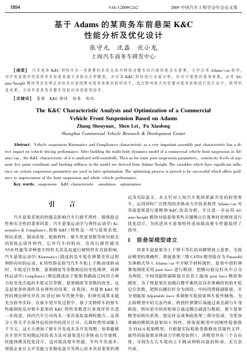
摇 摇 汽车悬架系统的性能是影响汽车行驶平顺性、 操纵稳定 性和安全性的重要因素。 汽车悬架运动学与弹性运动学( Ki鄄 nematics & Compliance,简称 K&C) 特性是一项与悬架系统、 转向系统、 制动系统、 轮胎特性、 整车质量参数等密切相关 的系统总成 外 特 性。 它 对 汽 车 的 转 向、 直 线 行 驶 性 能 及 NVH 性能等多种整车特性尤其是高速行驶特性有直接影响。 汽车悬架运动学( Kinematics) 描述的是车轮在弹簧变形过程 和转向时的运动, K 特性即是指当汽车车轮上下跳动或转动 时, 车轮定位参数、 悬架刚度等参数相应的变化规律。 而弹 性运动学( Compliance) 则是描述由于轮胎和路面之间的力和 力矩变化引起的车轮定位参数、 悬架刚度等参数的改变, 这 是悬架某些部件具有弹性的结果。 在我国, 对悬架 K&C 特 性的理论研究早在 20 世纪 80 年代便开始, 但研究成果未能 充分指导实际。 在新车型开发过程中, 基于实物样车的整车 性能调校是对整车悬架的 K&C 特性参数进行客观评价并进 一步改进。 国内汽车公司尚无一家具备底盘调校能力, 这部 分工作几乎全部外包给国外的设计公司, 且调校费用动辄上 千万元, 这大大增加了整车开发成本及开发周期。 如果能够 在车型开发初期运用仿真方法对悬架进行多体动力学建模、 性能预测及优化设计, 这对提高整车性能、 节约开发成本、 增强企业自主开发能力掌握底盘开发核心技术具有重要的理
摇 摇 揖 关键词铱 摇 悬架摇 K&C 特性摇 仿真摇 优化
The K&C Characteristic Analysis and Optimization of a Commercial Vehicle Front Suspension Based on Adams
用于不稳定性分析的重型汽车动力传动建模

function of the pressure drop through the valve with the classical Barré de Saint Venant equations (1,2), that are
valid for subsonic and sonic flows (assuming a perfect gas).
H. Defay, Renault Vehicules Industriels, St Priest, France
ABSTRACT This paper presents the construction of a heavy truck powertrain model used to reproduce and analyze instability phenomena, sometimes called “surge phenomena”. In many practical cases, the design or improvement of dynamic systems can be done using an experimental approach but it is often expensive, complex to perform, and time
Injection
ECU
Engine load
Driver
Engine d
Heavy Truck IC Engine
Gear Box
Diff.
Wheel
Figure 1 – The Heavy Truck Powertrain
THE IC ENGINE As for most heavy trucks, the heart of the powertrain lies in the engine, which is an internal Ignition-Compression engine. The choice for the Diesel is mainly justified by consumption gains but also by the necessity for high torques
横向稳定杆侧滑问题的分析及改进

横向稳定杆侧滑问题的分析及改进王晓莲;张学博;洪良;张维远;徐琢【摘要】目前,国内客车用横向稳定杆普遍存在侧滑问题,导致稳定杆及悬架系统性能和可靠性下降、异常磨损、异响严重.本文通过一客车道路试验反馈,分析导致稳定杆侧滑的根本原因,制定改进措施,并利用ABAQUS软件进行仿真分析.【期刊名称】《客车技术与研究》【年(卷),期】2018(040)002【总页数】4页(P23-26)【关键词】横向稳定杆;侧滑问题;改进措施;仿真分析【作者】王晓莲;张学博;洪良;张维远;徐琢【作者单位】一汽解放汽车有限公司商用车开发院,长春 130011;一汽解放汽车有限公司商用车开发院,长春 130011;一汽解放汽车有限公司商用车开发院,长春130011;一汽解放汽车有限公司商用车开发院,长春 130011;一汽解放汽车有限公司商用车开发院,长春 130011【正文语种】中文【中图分类】U463.33横向稳定杆是防止汽车在转弯时发生过大的横向侧倾,保持汽车平衡的悬架系统重要零件,可提高车辆的操纵稳定性,提升舒适性和安全性[1-2]。
若稳定杆与其橡胶衬套间发生侧滑,不仅会使稳定杆的性能下降,还会发生左右窜动,影响悬架系统的性能及可靠性。
本文针对某客车横向稳定杆与其衬套之间发生侧滑的问题进行分析,并与道路试验反馈信息、台架试验结果和ABAQUS仿真分析结果相结合,对稳定杆与其衬套系统进行改进和验证。
1 原因分析根据某客车道路试验反馈,前悬架横向稳定杆与衬套之间发生左右侧滑的现象,如图1(a)所示。
发生侧滑现象的稳定杆左右两端均与衬套间出现明显间隙,如图1(b)所示,间隙测量结果如表1所示。
(a)(b)图1 发生侧滑的横向稳定杆表1 稳定杆与衬套间隙测量表 mm位置稳定杆外径衬套内径间隙左侧⌀40 12⌀42 452 33右侧⌀40 08⌀41 891 81本文从衬套结构、衬套与支架和稳定杆间的连接结构两个方面分析、总结出原因如下。
一种重卡管状横梁断裂的失效分析及改善方法

收 稿 日期 :02— 4—1 21 0 3
作者简 介 : 剑波 (9 0 ) 男 , 谢 18 一 , 工程硕士 , 工程 师 , 主要从 事重卡动力系统 的产品开发和改进研究 。
6 8
四 川 兵 工 学 报
ht :/ c gjusr. o t / sb .o r v cm/ p e
—
96.
( 责任 编 辑
鲁
进)
( 接第 6 上 5页 )
对 于 主 轴 的 动 态 性 能 研 究 , 时 间 与 过 程 的 角 度 , 在 从 旨
为提高主轴运作 的高效性与准确性 提供依据 , 此可 以提高 如 加工精度 。动态 性能 包括 力学性 能 , 动频 率等 各种 性 能。 振 对机床主轴工作 状态下的动态性能 的评估 , 更好地把 握机 能 床 的工作性 能与机床 的发展 。
扩张应力 。② 应 力 腐 蚀 断裂 是 一 种 与 时间 有关 的滞 后 破 坏, 这和氢滞后开 裂 完全 类似 。③ 应 力 腐蚀 开裂 是 一种 低
应力脆性 断裂 。 该 管 状 梁 一 般 出现 断 裂 的部 位 在 发 动 机 着 力 点 上 , 接 焊
参 考文献 :
胡 玉梅 , 士 星 , 以轩 , , 动 机 悬 置 系统 优 化 方 法 张 向 等 发
直板 时热 影响区域较 大 , 使局 部材 质 的应力 发生 变化 , 因此
才 出 现 了 轴 向 方 向 的垂 直 断 裂 。
发生脆性断裂 的原 因是存 在和焊缝相 交 的构 造缝 隙 , 或 相 当于构造缝 隙的未透 焊缝 。构造焊缝 相当 于狭 长 的裂纹 , 造成 高度 的应力集 中 , 焊缝则造成高额 残余 拉应力并使 近旁
Tacoma大桥风振致毁事故机理分析与模拟
Z A igx n E X uk n S O H i H 0 Qn n et n a t E g er g C a ghuU i r t,C aghu2 36 C i ) Sh o o v o m n adSfy ni ei , hnzo nv sy hnzo 1 14, hn E r e n n ei a
第 7卷 第 1 期 l 21 0 1年 1 1月
中 国 安 全 生 产 科 学 技 术
J un lo aey S in e a d T c n lg o r a fS ft ce c n e h oo y
V0 . 17 No. 1 1 NO 2 1 V. 01
文章编号 :6 3—13 2 1 ) l一 0 1 0 17 9 X(0 1 一1 0 4 — 5
i hto h l.Att e s me tme t e pr su e lw r a wa r d al o me tte o o ie,t e v d t h fg ft e wa1 h a i h e s r o a e sg a u ly f r d a h pp st h n mo e o t e
称性的破缺及其 诱发 桥梁振动的机 理 ; 过建立 数值计算 模型 , 并通 采用 Fun软 件对其进 行 了仿 l t e
真计算 。结果显示 : 当风速超过 l / 时 , m s 桥面 上下侧压 力对称 性开始破 缺 , 压 区从桥 面 的正下 低 方( 或正上方 ) 逐渐 向右移动 , 过右边墙 后消_ , 跨 久 ¨时在相反 的一侧逐步形成低压 区 , 然后又 向右 移 动并 逐渐消失 , 如此周期 交替变化 , 并且 在不 同的风速 条件下 , 交替变化 的频率不 同, 其值 随着 风速的增加 而逐步增 大 , 但增长速率却 随着风速 的增加逐渐减小 。 关键词 :ao 大桥 ; T cma 对称性破 缺 ; 低压区 ; 风振
减震技术丨国外减隔震桥梁的失效分析
减震技术丨国外减隔震桥梁的失效分析大多数桥梁专家以及相关的媒体都过于推崇桥梁的正面效应,如美观的外形特征、交通问题的解决程度以及结构设计上的创新点等等。
然而,无论在国外还是国内,桥梁的失效案例都屡有发生,而对其失效的原因却鲜见详细科学的报道和分析。
这对于桥梁事业的进步和发展是不利的,它导致了完全可以避免的错误接踵发生。
案例一:博卢高架桥1号线概况1999年,土耳其西部发生了7.2级大地震,据统计共造成1000多人死亡,5000多人受伤,震害区绝大多数建筑物都遭到了破坏。
当时,作为连接土耳其博卢省西部和山岭地区交通枢纽的博卢高架桥工程几乎已经竣工。
采用了“先进”的隔震和耗能技术的博卢高架桥1号线却在此次地震中没能幸免,遭到了严重的破坏博卢高架桥失效原因分析博卢高架桥的破坏引起了许多地震工程和桥梁工程界人士的高度重视。
在大地震发生以后,美国M.C.Constantinou教授等人多次对该高架桥进行设计和破坏的深入调查和研究。
他们的结论是:博卢高架桥的破坏是由于其结构保护系统(即地震隔离系统)的失效所引起。
根据计算分析结果并结合现场调查,指出了地震隔离系统的设计存在以下严重问题:1.隔震系统的位移能力不足。
依据AASHTO标准验算可得,该高架桥隔震系统的最大位移为820mm。
而原设计的隔震系统的极限位移仅有210mm(滑动支座)——480mm(屈服耗能装置的极限位移)。
通过利用博卢和达兹两处地震观测站分别对地震场地进行了地面运动情况的观测,并模拟了近断层的运动情况,得到的峰值位移应为1400mm。
这巨大的差别说明了该设计不仅非常不合理(隔震的两部分位移能力不同),也远远不能满足达兹近场大地震的要求。
2.屈服后的刚度值偏低。
为了确保隔震装置在地震中能自动回复原位,在1991年或1999年的AASHTO设计规范中均要求,在设计50%最大位移时,装置的横向恢复力应大于支座承受重力的2.5%。
该支座承受的重力为14200kN,50%的最大位移160mm时的恢复力仅有1652kN,为重力的1.2%。
Ksport AirTech 空气悬挂系统用户手册说明书
d in place.pressure of 70 psi until the vehicle is completely on the ground. This will prevent damage to the air bags.Ksport AirTech Air SuspensionOwner’s ManualBefore starting your installation, please read these instructions completely. Check that all parts are included and not damaged from shipping. Ksport AirTech kits do not require modification ofOEM suspension components. This is a bolt-on kit.Failure to read these instructions can result in damage to the product and or your vehicle.NOTE: This air suspension system must be installed by a qualified professional installer.Installation:a) Safely elevate the vehicle with a jack and jack stands or hydraulic lift. Remove wheels.b) Remove OEM strut & spring assembly. Install AirTech strut air bag assembly. For vehicles with a separaterear shock and spring, please see additional instructions included with your kit.c) Route and connect all air lines appropriately per your kits requirements. See diagrams below.d) Please make sure to disconnect your air line while adjusting ride height via the lower mount. Once rideheight is set, make sure to use the locking collar to secure the mount in place. We recommend using a chisel and hammer to make sure the collar is lockee) The shape and diameter of the airbag will change based on the air pressure in the airbag. Please ensure theairbag does not make contact with any parts of the vehicle at all air pressure settings. This is extremely important. If contact is made with any part of the vehicle it will void the warranty.f) Air Lines: The supplied air lines are made from PFT with I.D. 4mm, O.D 6mm, 280 psi, operatingtemperature of 80 degrees. Please ensure when routing the air lines that they have ample room and do not come in contact with exhaust piping, lower arms, axles, etc. Also keep in mind that the suspension moves up and down and during turning so it is imperative that the air lines do not come in contact with any moving parts.g) Setting the lowest ride height is at the vehicle owners’ discretion. Be aware that the air bags must not havecontact with any components of the vehicle, including wheel/tire, body, or suspension arms. Failure tomaintain correct minimum pressure will damage your air bags as well as shock absorbers. If the shocks are overextending, lower the vehicle. Likewise, if the shocks are bottoming out, the vehicle must be raised. With proper installation and setup, the Ksport air ride kit will provide excellent driving comfort and handling. If you hear any noises from your shocks or the ride is excessively bouncy, please review your installation andsetup. The highest ride height setting is not ideal for driving and should be used mainly for navigating around obstacles such as speed bumps, steep inclines, driveways, etc.h) When lowering the vehicle from a lift or jack stands, please be sure that the air bags maintain a minimumi) Ride height to air bag pressure will vary for every vehicle since not all vehicles weigh the same amount. Youmay have to adjust the airbag pressure depending on other variables such as how many passengers areinside the vehicle, heavy stereo system and fuel tank level. The gauges supplied with this system can beused to approximate ride height, however, based on varying loads minor adjustments may be needed toensure proper ride height from time to time.j) Basic & Deluxe kit only: Determine the mounting location of the gauge and the switch panel inside the vehicle. Be sure all lines and wires are routed so they do not interfere with anything that can damage thelines.k) Deluxe Kit only: The supplied remote can be used to adjust vehicle ride height while outside of the vehicle.Press and hold the appropriate button to raise or lower the vehicle. Release the button to stopraising/lowering the vehicle.l) Pro & Pro Plus only: For instructions on using and programming the OLED remote, please see the separate remote instruction guide.Electrical Components:a) Please review the included wiring diagram for your model kit to determine how to wire this system.b) It is highly recommended to install a relay on the +12v power wire for the compressor. The compressor canplace a high load on a vehicles electrical system; therefore they will not operate with the vehicle key in theOFF position. This is to preserve battery life.Inspection & Maintenance:a) To check for leaks inflate the air bags to 70 PSI. Spray all air line connections with a solution of soap andwater. Check for bubbles in the soapy water to determine if there is a leak. If a leak is found, reinstall the airline to the fitting.b) Deflate air bags to minimum pressure required for your chosen ride height and check the air pressure againafter 24 hours. A 2-4 PSI loss after initial installation is normal. Retest for leaks if the pressure loss is morethan 5 PSI after 24 hours.c) Air lines must be cut at straight angles. Air lines cut at an angle will not attach properly and can cause an airleak.d) Always check air pressure before driving.e) The Ksport Air Suspension systems use oil-less VIAIR compressors. Since they are oil-less they require lessmaintenance. However, because there is no oil, the compressor should not be running for long periods oftime as this can cause the compressor to overheat.f) The inside of your air tank will acquire condensation, and this water must be drained periodically. In mostcases, this should be done every 4-6 weeks. Please check your air tank often (every 2-3 weeks) during thefirst 6 months of ownership, in order to understand how often your particular setup gathers condensation.g) Periodically inspect air lines for holes and cracks. Replace as needed.h) We highly recommend rechecking your air suspension system after 500 miles of driving or 1 month,whichever comes first. If you notice any signs of rubbing on the air bags or air lines, the source should beidentified and remedied immediately. If your system was professionally installed, your installer should beconsulted. Recheck all fittings for tightness.Troubleshooting Guide:a) For some applications, the shock absorbers come with adjustable lower mount and the locking collar mustbe tightened with a hammer and chisel.If the locking collar is not completely tight there may be a clunking noise.b) All McPherson struts come with pillow ball upper mount which allows camber adjustment. Pillow ball mountsare known to cause slight noise, especially when set to extreme angles. To avoid potential noise, do not set the pillow ball to extreme angles.c) If the shocks are overextending, lower the vehicle. Likewise, if the shocks are bottoming out, the vehiclemust be raised.Warnings:a) Be sure to fuse the power wire running to the car’s battery. THIS IS REQUIRED.b) Attaching the air lines properly is very important. This kit is supplied with the retaining strips for the air lines.c) The adjustable lower mount must be tightened using a hammer and chisel/punch. Failure to do this will allowthe shock absorber to rotate, causing noise and tangling the air line. Also, prolonged driving with a looselower mount can cause extreme stress to the shock body.d) Ensure all compressors are functioning properly. If one is not functioning correctly, this will place additionalload on the other compressor(s) and lead to premature failure.e) Do not touch the compressor when it is operating. Also, shield the compressor from any heat sources in thetrunk.f) In some circumstances, in order to complete the installation of this product, drilling a hole in the car isnecessary to secure the air tank mounting board on the vehicle.g) Basic & Deluxe kit only: The switch is designed to adjust the vehicle ride height in the front or in the rear atthe same time, not for the left or right side height at the same time. The left and right sides have differentweight so there will be a slight difference in the vehicle ride height. The speed of lowering or raising thevehicle ride height in the fronts or in the rears might be different due to different chassis design of eachvehicle model.h) Basic & Deluxe kit only: If you desire to adjust the vehicle ride height in the front left OR front right OR rearleft OR rear right independently, you can purchase another 2 switches and 1 gauge from our company tomeet your requirements.i) This product is demonstrated for use in a show car only; therefore, we will assume no responsibility for anydamage to the vehicle or any injuries or death caused directly or indirectly by this product.(1) 5 gallon air tank with ¼” port (x2) and 3/8” port (x2)(1) Black carpeted mounting board(1) VIAIR 380c compressor(1) 165-200 PSI pressure switch(1) 30amp Relay(2) Manual paddle valve(1) 200 PSI dual needle gauge(3) 6mm 3-direction fitting(1) ¼ to 3/8 L-shape fitting(1) 6mm ¼ outer pitch fitting(1) Iron plug(1) 1/8PT to ¼ pitch fitting(4) Rivet(1) 35m ¼” air line(1) 5m power wire(4) High performance Ksport shock absorbers with 36 levels of damping and adjustable lower mount(4) High pressure air bags designed and engineered to match your vehicle(1) Tool kit including spanner wrenches, damping adjustment knobs & brake line brackets (application specific) (1) Owner’s manualDeluxe Kit Parts List:(1) 5 gallon air tank with ¼” port (x2) and 3/8” port (x2)(1) Black carpeted mounting board(2) VIAIR 380c compressor(1) 165-200 PSI pressure switch(2) 30amp Relay(2) Electronic switch w/mounting plate(1) 200 PSI dual needle gauge w/mounting plate(1) Electronic Control Unit(1) Remote control(3) 6mm 3-direction fitting(1) 10mm L-shape fitting(1) 10mm ¼” outer pitch L shape fitting(1) 6mm 1/8” inner pitch fitting(1) 1/8PT to ¼ pitch fitting(1) 3/8-1/4 fitting(1) Iron plug(1) 3/8” hose fitting(4) Rivet(1) 25m ¼” air line(1) 1m 10mm air line(1) 5m power wire(4) High performance Ksport shock absorbers with 36 levels of damping and adjustable lower mount(4) High pressure air bags designed and engineered to match your vehicle(1) Tool kit including spanner wrenches, damping adjustment knobs & brake line brackets (application specific) (1) Owner’s manual(1) 5 gallon air tank with ¼” port (x2) and 3/8” port (x2)(1) Black carpeted mounting board(2) VIAIR 380c compressor(1) 165-200 PSI pressure switch(2) 30amp Relay(1) Electronic Control Unit(1) OLED full color remote(1) USB vehicle charger for OLED remote (no battery change necessary)(1) Standard 3 button remote(2) 6mm 3-direction fitting(1) 10mm L-shape fitting(1) 10mm ¼” outer pitch L shape fitting(1) 6mm 1/8” inner pitch fitting(1) 1/8PT to ¼ pitch fitting(1) 3/8-1/4 fitting(1) Iron plug(1) 3/8” hose fitting(1) 25m ¼” air line(1) 1m 10mm air line(1) 5m power wire(4) High performance Ksport shock absorbers with 36 levels of damping and adjustable lower mount(4) High pressure air bags designed and engineered to match your vehicle(1) Tool kit including spanner wrenches, damping adjustment knobs & brake line brackets (application specific) (1) Owner’s manualPro Plus Kit Parts List:(1) 5 gallon air tank with ¼” port (x2) and 3/8” port (x2)(1) Black carpeted mounting board(2) VIAIR 380c compressor(1) 165-200 PSI pressure switch(2) 30amp Relay(1) Electronic Control Unit with 4 corner independent control(1) OLED full color remote(1) USB vehicle charger for OLED remote (no battery change necessary)(1) Standard 3 button remote(1) 10mm L-shape fitting(1) 10mm ¼” outer pitch L shape fitting(1) 1/8PT to ¼ pitch fitting(1) 3/8-1/4 fitting(1) 3/8” hose fitting(1) Iron plug(1) 25m ¼” air line(1) 1m 10mm air line(1) 5m power wire(4) High performance Ksport shock absorbers with 36 levels of damping and adjustable lower mount(4) High pressure air bags designed and engineered to match your vehicle(1) Tool kit including spanner wrenches, damping adjustment knobs & brake line brackets (application specific) (1) Owner’s manualKSPORT SUSPENSIONSUSPENSION SYSTEMS。
AMESim_用于不稳定性分析的重型汽车动力传动建模
HEAVY TRUCK POWERTRAIN MODELLING FOR INSTABILITIES ANALYSIS V. Thomas, IMAGINE, Roanne, France N. Janse van Rensburg, IMAGINE Software Inc., Detroit, Michigan H. Defay, Renault Vehicules Industriels, St Priest, France ABSTRACT This paper presents the construction of a heavy truck powertrain model used to reproduce and analyze instability phenomena, sometimes called “surge phenomena”. In many practical cases, the design or improvement of dynamic systems can be done using an experimental approach but it is often expensive, complex to perform, and time consuming. In these cases a numerical model allows quick sensitivity analysis on parameters and evaluation of suggested technical solutions. In this study the dynamic systems simulation software AMESim® is used because it contains numerous specific model libraries that limits the development work necessary and is based on an advanced numerical integrator. Furthermore, AMESim® has the ability to take non-linear effects into account and is able to mix discrete and continuous models in a single system. THE SURGE PHENOMENON [1,2] Vehicle vibration due to the excitation of driveline torsion modes by the engine is called “pumping”. Pumping causes driver discomfort and may lead to severe powertrain damage. This kind of problem initially appeared during the seventies when new requirements for high torque engines were set. The instability currently studied has been identified by consumers that complain about driver discomfort and in some severe cases of vehicle breakdown. The problems occur on heavy trucks with an electronic injection control system (associated with a mechanical in-line pump). The surge phenomenon corresponds to strong oscillations of the powertrain resulting from the coupling between the vibrations of the driveline and the unsteady torque delivered by the engine and produced by combustion. Thus, the injection control system behaviour is of major importance since it determines the shape of the in-cylinder pressure as a function of the engine operating point. The main vehicle characteristics which can cause “ pumping” are: • The method of injection control (mechanical or electronic injection) • The driveline vibratory characteristics (defining the possible unstable configurations in the powertrain). POWERTRAIN MODELLING The powertrain of the heavy truck can be divided into three main sub-systems. These are the engine, the driveline and the injection control system. Each sub-system is modelled as simply as possible since the purpose of the study is to analyse the couplings between systems and not the exact dynamic behaviour of each element.
- 1、下载文档前请自行甄别文档内容的完整性,平台不提供额外的编辑、内容补充、找答案等附加服务。
- 2、"仅部分预览"的文档,不可在线预览部分如存在完整性等问题,可反馈申请退款(可完整预览的文档不适用该条件!)。
- 3、如文档侵犯您的权益,请联系客服反馈,我们会尽快为您处理(人工客服工作时间:9:00-18:30)。
AnalysisofanunusualMcPhersonsuspensionfailureD.Colombo*,M.Gobbi,G.Mastinu,M.PennatiPolitecnicodiMilano,DipartimentodiMeccanica,viaLaMasa,34,20156Milano,Italy
articleinfoArticlehistory:Received4September2008Accepted6September2008Availableonline12September2008
Keywords:McPhersonsuspensionDefecttolerantDefectsShortcracks
abstractInthispaperthecauseofprematurefailureoftheupperstrutmountofaMcPhersonsus-pensionisinvestigated.Theworkwaspromptedbythefactthatthefailedcomponenthasbeenusedforatleastfourdecadesbyacarmanufacturerwithoutreportinganyprematurefailureandthereforeanindepthstudyofthestructuralbehaviorofthecomponentwasrequired.Bothexperimentaltestsandnumericalanalyseshavebeencarriedoutinordertoestimatetheservicelifeofthecomponent.Thefatiguelifeofthecomponenthasbeenassessedbyadefecttolerantanalysis.Theresultoftheinvestigationisthattheupperstrutmountfailurewasduetoanimpulsiveloadthatcannotbejustifiedbythestaticanddynamicloadsactingonthecomponentcausedbyroadirregularitiesandvehiclemanoeu-vringduringusualworkingconditions.Ó2008ElsevierLtd.Allrightsreserved.
1.IntroductionThisworkaimstoinvestigatetheunusualfailureoftheupperstrutmountofaMcPhersonsuspension.Mostfront-wheeldrivevehiclescomingontothemarkettodayhaveMcPhersonstruts.ThemainadvantageoftheMcPhersonisthatallthepartsprovidingthesuspensionandwheelcontrolarecombinedintooneassembly.Theupperstrutmountisthekeycom-ponentforinsulatingthechassisagainstroadnoise,but,ingeneral,itisnotcriticalfromthereliabilitypointofview.Inspiteoftheseevidences,theauthorsfacedwithafailedupperstrutmount.Themanufacturerofthevehicleurgedtomakeanindepthstudyofthecomponentinordertomakeanassessmentofitsstrength.Itshouldbeemphasizedthatthecomponenthasbeenproducedandusedforyearswithoutreportinganyprematurefailure.Inordertoinvestigatethecauseoffailurebothexperimentalandnumericalstudieshavebeencarriedout.Firstofall,thefracturesurfacehasbeenobservedandabrittlefailurehasbeenrevealed.Nocrackpropagationhasbeendetected.Consid-eringthefactthatthematerialcomposingtheupperstrutmountofthesuspensionisanaluminiumalloy(A357),confirmedbyachemicalanalysis,thefailurecanbeexplainedonlybytheactionofanimpulsiveload.However,verylargeporositieshavealsobeenobserved.Eveniftheyarecommoninaluminiumcastings,theyrepresentdefectsinthematerialmicrostruc-turefromwhichfatiguecrackscannucleateandpropagate.Fromtheseevidences,extensiveanalysesofthecomponenthavebeencarriedout.Inordertochecktheresistanceoftheupperstrutmounttoimpulsiveloads,atestonavehiclemountingthesamesuspensioncomponenthasbeenperformedbyusingsevereobstacles.Atthesametimetheeffectofthelargeporositiesonthefatiguebehaviorofthecomponenthasbeeninvestigatedbymeansofanumericalsimulationandadefecttoleranceassessment.Theresultofthesestudiesbroughttheauthorstotheconclusionthatthecomponentissafefromafatiguepointofviewalsoundersevereworkingconditions.Moreover,thecomponentcansustainalsohighextraordinaryimpulsiveloadswithoutreportinganyfailure.Therefore,thefailureoftheupperstrutmountcanbeexplainedonlybytheactionofanextremelyhigh
1350-6307/$-seefrontmatterÓ2008ElsevierLtd.Allrightsreserved.doi:10.1016/j.engfailanal.2008.09.001
*Correspondingauthor.E-mailaddress:daniele.colombo@polimi.it(D.Colombo).
EngineeringFailureAnalysis16(2009)1000–1010ContentslistsavailableatScienceDirectEngineeringFailureAnalysis
journalhomepage:www.elsevier.com/locate/engfailanalimpulsiveloadthatcannotbejustifiedbythestaticanddynamicloadsactingonthecomponentcausedbyroadirregular-itiesandvehiclemanoeuvringduringusualworkingconditions.Itshouldbeemphasizedthatthecaseanalysedinthispaperrepresentsaninterestingexampleofusageofthedefecttoleranceasanimportantdesigntoolfortheassessmentofthefatiguelifeofastructuralcomponentinordertoavoidcatastrophicfailures.Moreover,theengineeringsimplificationsadoptedforthenumericalmodellingoftheupperstrutmountrepresentsaninterestingsolutionthatsimplifiesthemodellingofsuchkindofcomponents.Inthefollowingparagraphstheexperimentalandnumericalanalysiscarriedoutonthecomponentaredescribed.
2.ResistanceoftheupperstrutmounttoimpulsiveloadsInordertochecktheresistanceoftheupperstrutmounttohighextraordinaryimpulsiveloadsanexperimentaltesthasbeencarriedoutinwhichavehicleequippedwiththesamecomponenthasbeenforcedtopassoverasevereobstaclewithsection70Â180mm(Fig.1)simulatingasidewalk.Thisisnotsupposedtohappeninnormalworkingconditionanditrep-resentsanextraordinaryworkingcondition.Thevehicleforwardingspeed(33±2km/h)hasbeenmonitored.Thestrainmeasuresontheupperstrutmounthavebeencarriedoutbyusingstrain-gaugesrosettesforaluminiumalloy(typeHBM1-RY13-6/120).ThepositioningoftherosetteisshowninFig.2.Thethreeanalogsignalsofthestrain-gaugerosettehavebeenacquiredbymeansofaSPIDER8HBMacqui-sitionsystemwithclassofaccuracy0.1.Theacquisitionfrequencyis200Hz.Thesignalshavebeenfilteredthroughlowpass