table_04_06 Energy Consumption by Mode of Transportation
esco业务模式(ESCObusinessmodel)

esco 业务模式(ESCO business model)EMCo business modelThe energy services company (EMCo) provides energy efficient services to customers by signing contracts for energy conservation services. EMCo is a special enterprise, its particularity is that it does not sell a specific product or technology, but such a series of services ”, also is to provide energy saving projects for customers, essence of this project is EMCo sales to customers of enterprise energy saving. EMCo' s business activities mainly include the following "one-stop” service content (for example of energy saving benefit sharing contract):1.energy audit (energy-saving diagnosis) EMCo for the specific circumstances of the customer, the enterprise energy consumption, energy saving equipment and measures to evaluate. Determine the current energy use of the enterprise and forecast the energy savings of alternative energy saving measures.2.energy-saving project design according to the energy audit (energy saving diagnosis) the results of EMCo to the customer and puts forward how to use energy-saving technology / mature energy-saving products or solutions to improve energy efficiency and reduce energy consumption cost plan and suggestion. If the customer has the intention to accept the proposal and suggestion put forward by EMCo, EMCo will carry out specific energy saving project design for the customer.3.negotiation and signing of energy saving service contract, EMCo negotiate with customers, sign energy-saving service contract on energy-saving project”. In some cases, if the customer does not agree to sign an energy saving contract with EMCo, EMCo will charge customers the upfront fees such as energy audits and energy saving project design.4.energy-saving project financing EMCo energy saving project investment or customers to provide financing services for such projects, EMCo may be the source offunding EMCo' s own funds, commercial bank loans or other financing channels (in the following chapters will be discussed in detail). Help enterprises to overcome the financing difficulties of energy-saving projects.5.raw materials and equipment procurement, construction, installation and commissioning, EMCo responsible for energy-saving projects of raw materials and equipment procurement, as well as construction, installation and commissioning work, similar to the implementation of turnkey project”.6.operate, maintain and maintain the EMCo, train the equipment operators for the customers, and be responsible for the maintenance and maintenance of the equipment / systems installed. After the project period, EMCo can continue to provide paid operation, maintenance and maintenance work at the request of the client enterprise or through consultation.7.energy efficiency guarantee EMCo to provide customers with energy saving project energy guarantee, and with customers or introduce third parties to monitor and confirm energy-saving projects in the contract period of energy-saving effect.8.EMCo share with customers on energy efficiency projects within the contract period, EMCo investment related to the project (including construction, raw materials, equipment and Technology) ownership, energy efficiency and share with customers generated by the project. The ownership of the equipment will normally be transferred to the customer after the project funds, operating costs, risks and reasonable profits of the EMCo are compensated (at the end of the contract period). Customers will eventually receive energy efficient equipment and energy savings costs, and enjoy all energy saving benefits.The contractual relationship between EMCo and the specific implementation of energy-saving projects is called "energy saving service contract"". EMCo's way of doing business is called "contract energy management.,,,r.Based on the new energy-saving energy management contract mechanism and EMCo mode of operation is described, we think it management and several ways are different: from that, EMCo is the energy conservation service commercial entities in the market economy environment, to seek survival and development in the market competition, and China's current belongs to the local government, energy saving service the center has some of the functions of government are fundamentally different.9.the ownership of the project is presented to the customer. After the completion of the contract period, the energy-saving service company shall present the ownership of the project (including civil engineering, raw materials, equipment,technology, etc.) to the client.1.. Differences in sales practices with equipment manufacturers, distributors and trade intermediariesAlthough the EMCo raw materials and equipment to provide for customers for energy saving, but it is not just a manufacturer or supplier provides a single equipment, but all the required energy saving technology, raw materials and equipment, and in accordance with the contract requirements for a series of services to ensure energy-saving effect to customers in the contract equipment the ownership of EMCo, so the sales behavior is not equivalent to the general equipment manufacturers, of course, but also different from the profit for the sale of all the company to trade behavior.2.differences from technical services and adviceAlthough EMCo provides customers with the procurement, installation, commissioning, operation and maintenance and other services, but an integral part of these is the whole project, is a financing and a variety of technical services, system. Unlike general technical services, advisory bodies,Provide only technical services or advice in a certain area without financing services. 3., the difference between "financial leasing" and "financial leasing”Generally speaking, leasing can be divided into operating lease and financial lease. Under the existing enterprise financial system in China, "financial leasing" refers to the equipment leasing business with the characteristics of financial leasing and ownership transfer. Namely: the lessor according to the lessee the required specifications, models, performance and other conditions to purchase equipment leased to the lessee, the contract period of equipment ownership belongs to the lessor, the lessee has the right to use, pay the rent after the expiration of the contract, the lessee has the right to choose to buy equipment to salvage, complete with the use of equipment the right of ownership and. And contract energy management between the two there is a great difference: (1)in the "financial leasing”, the leasehold property is limited to equipment, althoughthe contract period of ownership still belongs to the lessor, but in essence, the substancehas been attributed to the ownership of the lessee, the most obvious feature is the"accumulated depreciation equipment" is extracted by the lessee and the lease. Almostcover the entire equipment life period of about 75%; and EMCo the contract not onlyraw material and equipment, including the service, the subject matter of the project, thecontract period is only the life of 1/3 or less, and, in the period, the substance of theownership of the equipment is completely on the project owned by EMCo.(2)in the "financial leasing”, approved by the people' s Bank of Chinese the lessor tothe lessee only provide rental this service: but EMCo not only for customers topurchase complete set of equipment and raw materials, but also for the period of thecontract design, installation, testing, commissioning, maintenance, training, consultingand ensure energy-saving effect and a series of services.(3)in the "financial leasing”, the lessor does not guarantee rental equipment may useeffect to the lessee in the lease period, the subject of equipment maintenance,renovation costs borne by the lessee, and the lessor in accordance with the relevantprovisions of the state and the relevant provisions of the lease contract to collect rentalfees : the primary task of EMCo is to ensure that the energy saving effect, only toensure established in contract energy, both sides can realize the benefit sharing, to mutual benefit, EMCo can share many benefits, and can fully realize how much energy linked and appear in the contract period caused by non equipment failure caused by illegal customers the losses are borne by EMCo.(4)the nature of the funds recovered by the two parties is differentThe amount of money payable in a finance lease is called rent, which includes the original price, interest and rental charges (excluding maintenance, maintenance, etc.) of the leased asset. Considering the time value of money, will each pay rent according to certain interest discount to present value, during the period of the contract should be the same (except the last including bianjiashouru outside) ; while the EMCo every time the recovery of funds is the energy linked with the festival reached, only to meet or exceed the stipulated in the contract energy, the provisions in the contract can be repaid in full amount in the contract period may change.Although the contract energy management and financing lease with the difference, but with the contract energy management mechanism in our country's further development and practice, some companies have begun to introduce the mode of financing lease as a means to solve the problem of financing, and even part of the energy service company also became leasing company, using some lease financing policy, combined with the characteristics of energy contract management mechanism, the implementation of energy-saving projects.4., the difference between "loan" and "loan”EMCo and financial investment companies are also very different in nature. The difference between the first to analyze the overall services and lending EMCo, EMCo provided is energy-saving projects all in one service, but also in accordance with the contract to the customer to ensure energy-saving effect, these are the lenders may not matter, there is no need to pipe, pipe. Although EMCo has the same financial risk andcustomer reputation risk as the lender, they also fully undertake technical risk, contract execution risk, energy efficiency, excessive risk and market risk.5., the difference between "investment" and "investment”Investors invest enterprise funds, not only for one project, but as equity capital into the enterprise, and credited to the z/owner s' equity" account, thus, investors will become the owner of the invested enterprises, and enterprises to take all the risk to be faced in the process of operation. Of course, while performing their obligations, they also have the right to share all the benefits in proportion to their investment. If there is no other reason, these funds are not specifically specified for the repayment period. And EMCo' s service is only for an energy-saving renovation project, it is to assume only the project is facing all the risks,What is shared with the customer is only the energy saving benefits generated by the project. It does not involve other aspects of the customer' s business, and this sharing is also a deadline, not covering the entire project life cycle.EMCo itself may not be able to do all the services, but as a professional energy-saving service company, EMCo can integrate all kinds of external resources to achieve the contract energy. The following types of organizations may be involved:Basic types of energy saving service contractsThe most important part of the energy service contract involves: how to determine the reference line, how to calculate and confirm the detection, energy saving, enterprise customers how to EMCo payment terms, a clear statement of the relevant content and let the customer understand in the contract, is extremely important.According to the responsibilities / obligations of customers, enterprises and EMCo, and the ways in which customers pay to EMCo, the energy-saving service contracts can bedivided into different types. With the continuous development of the contract energy management mechanism in China, there have been three different types, which are similar to those in NorthAmerica, Japan and South korea.1.energy-saving benefit sharing type of contract, the provisions of the EMCo responsible for project financing, during the project period, customers and EMCo share energy-saving efficiency of both sides.The main features are as follows:L energy-saving projects (energy-saving income accounted for more than 50% of the total revenue of the whole project);L EMCo provides funding for the project:L EMCo provides the whole process service of the project:L contract provides energy saving targets and methods for detecting and confirming energy saving (or energy saving rate);L during the contract period, EMCo and the customer share energy saving benefits according to the contract. After the conclusion of the contract, all the equipment and energy saving benefits shall be owned by the client enterprise.For example, in the 5 year project contract period, customers, enterprises and EMCo share 20% and 80% of the energy efficiency respectively, and EMCo must ensure that the project costs and profits are recovered during the contract period. In addition, the proportion of energy sharing benefits can be changed between the two parties during the contract period. For example, in the first 2 years of the contract period, EMCo shared 100% of the energy savings benefits, and 3 years after the contract period,customers and EMCo each shared 50% of the energy efficiency.2.energy conservation type, in this type of contract, EMCo guarantees that the customer's energy costs will be reduced by a certain percentage, which can be provided either by project financing by EMCo or by customer financing.The main features are as follows:L energy saving project:L customers provide all or part of the project's funds:L EMCo provides the whole process service of the project:L contract provides energy saving targets and methods for detecting and confirming energy saving (or energy saving rate);L contract clearly states: if the contract period of the project did not meet the promised energy, EMCo by the payment of all outstanding energy loss of energy:L customers pay the service charge to EMCo and the funds invested by EMCo.For example, EMCo guarantees a 10% reduction in fuel costs for customer boilers, while all additional energy savings benefits go to EMCo.3.energy cost management type, in this type of contract, the EMCo is responsible for managing the operation and maintenance of the whole energy system of the customer enterprise, contracting energy costs.The main features are as follows:L energy saving project:L according to the standard stipulated in the contract, EMCo manages and reforms the energy system for clients and contracts energy costs;L contract stipulates that the quality standards for energy services and the methods for their confirmation shall be compensated by contract when the EMCo fails to meet the standards;The economic benefits of L EMCo come from the conservation of energy costs, and the economic benefits of customers come from the reduction of energy costs (contracts)As things stand, most contracts are one of three ways or combinations of the above. For each kind of payment method, may make the suitable adaptation, adapts the different energy dissipation enterprise' s concrete situation and the energy conservation project special request.However, no matter which mode of payment is adopted, the following principles should be followed:Both the U EMCo and the customer must fully understand the terms of the contract:The U contract is fair to both the EMCo and the customer to maintain a good business relationship:The U contract shall encourage both the EMCo and the customer to pursue the maximum possible energy and to ensure that the equipment is maintained continuously and in good operation throughout the contract period.Domestic EMC Contract Energy Management Alliancez/Guangdong green industry investment fund for energy-saving emission reduction policies to actively implement the national and provincial government of Guangdong,to promote energy-saving emission reduction, the development of low-carbon economy, the revitalization of Guangdong LED in the energy industry, science and Technology Department of Guangdong provincial government, Guangdong green industry investment fund led the establishment of Guangdong green Industry Alliance Investment Fund EMC.The EMC alliance is energy-saving equipment manufacturers by Guangdong green industry investment fund co registered in the territory of China (LED lamp factory), energy-saving equipment suppliers of raw materials (LED lamp chip factory, power plant and so on) and financial institutions (banks, guarantees, leasing, insurance, trust, etc.) detection mechanism, construction engineering company, engineering design company, bidding companies, law firms, contract energy management services company (EMC company) and other related enterprises and institutions.All rights EMC alliance members will enjoy the alliance brought to its production, enterprises can obtain financial support from banks, the industry outstanding enterprises meet the fund conditions can obtain funds to support the market, the added value of other projects will also have the opportunity to get the fund investment in Guangdong province 25 billion yuan LED street reconstruction contracts and other provinces. Green lighting industry contract and contract.。
各国能效要求标准

≥ 0.84
umption Criteria for No Load(能效等级4 空载功耗)
Maximum Power in No-Load ≤ 0.5 watts ≤ 0.75 watts
Nameplate Output Power (Pno)
0 to ≤ 1 watt > 1 to ≤ 49 watts
> 49 watts
Table 4: Energy Consumption Criteria for No-Load (空载功耗)
NaБайду номын сангаасeplate Output Power (Pno)
能源之星5.0标准
Table 1: Energy-Efficiency Criteria for AcAc and Ac-Dc External Power Supplies in Active Mode: Standard Models (普通机 型)
Nameplate Output Power (Pno)
能源之星5.0标准
Minimum Average Efficiency in Active Mode (expressed as a decimal) 2
≥ 0.480 * Pno + 0.140
≥ [0.0626 * Ln (Pno)] + 0.622
≥ 0.870
0.8446 0.71
Minimum Average Efficiency in Active Mode (expressed as a decimal) 2
≤ 0.5 watts
能源之星4.0标准
Efficiency Criteria for Active Mode (能效等级4)
英语作文表格类型模板

英语作文表格类型模板Title: Analyzing Trends in Global Energy Consumption (Title can be adjusted as per your specific topic)。
Introduction:In today's interconnected world, understanding trendsin energy consumption is paramount for policymakers, businesses, and individuals alike. This essay aims to analyze recent trends in global energy consumption based on data provided in the table below. By examining these trends, we can gain insights into the shifting dynamics of energy usage across different regions and sectors.Table: (You can insert the table here)。
Analysis:1. Regional Disparities:The table reveals significant regional disparitiesin energy consumption. North America and Asia-Pacific emerge as the top consumers, accounting for the majority of global energy usage. This reflects the economic growth and industrial development in these regions.Europe, while still a significant consumer, exhibits relatively lower energy consumption compared to North America and Asia-Pacific. This could be attributed to greater emphasis on energy efficiency measures and renewable energy adoption in European countries.2. Sectoral Breakdown:Analyzing energy consumption by sector provides valuable insights into the drivers of energy demand. The industrial sector stands out as the largest consumer across all regions, underscoring its pivotal role in energy usage.The residential and commercial sectors also contribute substantially to energy consumption,highlighting the importance of addressing energy efficiencyin buildings and households.Interestingly, the transportation sector,particularly in North America, shows a considerable share of energy consumption. This emphasizes the need for sustainable transportation solutions to mitigate environmental impact.3. Shift towards Renewable Energy:While fossil fuels continue to dominate the energy mix, there is a discernible shift towards renewable energy sources. This is evident from the growing share of renewables in total energy consumption, especially in Europe and Asia-Pacific.Government policies, technological advancements, and increasing awareness of climate change drive thistransition towards renewables. However, challenges such as intermittency and storage need to be addressed to accelerate the adoption of renewable energy on a larger scale.4. Implications for Policy and Business:Policymakers need to formulate strategies that promote energy efficiency, incentivize renewable energy deployment, and foster international cooperation to address global energy challenges.Businesses should seize opportunities arising from the transition to a low-carbon economy by investing in clean energy technologies, implementing energy-efficient practices, and adapting their operations to meet evolving consumer preferences.Conclusion:In conclusion, the analysis of global energy consumption trends provides valuable insights into the complex interplay of factors shaping the energy landscape. While challenges such as regional disparities and reliance on fossil fuels persist, there are promising signs of a transition towards cleaner and more sustainable energysources. By leveraging these insights, stakeholders can work towards a more resilient and environmentally responsible energy future.(Note: You can customize the analysis based on the specific data provided in the table.)。
CEC

6
Appendix Y in test procedure
The provisions of this appendix are effective on the compliance date of any energy conservation standard for battery chargers. 1. Scope This appendix covers the test requirements used to measure battery charger energy consumption for battery chargers operating at either DC or United States AC line voltage (115V at 60Hz). 2. Definitions The following definitions are for the purposes of explaining the terminology associated with the test method for measuring battery charger energy consumption.1 1 For clarity on any other terminology used in the test method, please refer to IEEE Standard 1515– 2000. 2.1. Active mode or charge mode is the state in which the battery charger system is connected to the main electricity supply, and the battery charger is delivering current, equalizing the cells, and performing other one-time or limited-time functions in order to bring the battery to a fully charged state. 2.2. Active power or real power (P) means the average power consumed by a unit. For a two terminal device with current and voltage waveforms i(t) and v(t), which are periodic with period T, the real or active power P is:
能源之星--6级能效标准
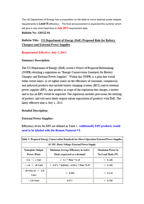
The US Department of Energy has a proposition on the table to move external power adapter requirements to Level VI efficiency. The final announcement is expected this summer which will give a very short lead-time to July 2013 requirement date.Bulletin No: 120322-01Bulletin Title:US Department of Energy (DoE) Proposed Rule for Battery Chargers and External Power SuppliesRequirement Effective:July 1, 2013Summary Description:The US Department of Energy (DoE) issued a Notice of Proposed Rulemaking (NOPR) detailing a regulation on “Energy Conservation Standards for Battery Chargers and External Power Supplies”. Within this NOPR, is a plan that would either create limits, or set tighter limits on the efficiency of consumer, commercial, and industrial products that include battery charging systems (BCS) and/or external power supplies (EPS). Any product in scope of the regulation that charges a battery and/or has an EPS would be impacted. The regulation includes provisions for labeling of product, and will most likely require online registration of products with DoE. The likely effective date is July 1, 2013.Detailed Description:External Power Supplies:Efficiency levels for EPS are defined in Table 1. Additionally EPS products would need to be labeled with the Roman Numeral VI.Table 1: Proposed Energy Conservation Standards for Direct Operation External Power SuppliesAC-DC, Basic-Voltage External Power SupplyNameplate Output Power (Pout)Minimum Average Efficiency in ActiveMode (expressed as a decimal)Maximum Power inNo-Load Mode [W]0 to ≤ 1 watt≥0.5 * Pout + 0.16≤ 0.100 > 1 to ≤ 49 watts≥0.071 * ln(Pout) - 0.0014 * Pout +0.67≤ 0.100 > 49 watts to ≤ 250watts≥ 0.880≤ 0.210 > 250 watts0.875≤ 0.500AC-DC, Low-Voltage (<6V) External Power SupplyNameplate Output Power (Pout)Minimum Average Efficiency in ActiveMode (expressed as a decimal)Maximum Power inNo-Load Mode [W]0 to ≤ 1 watt≥0.517 * Pout + 0.087≤ 0.100 > 1 to ≤ 49 watts≥0.0834 * ln(Pout) - 0.0014 * Pout + 0.609≤ 0.100 > 49 watts to ≤ 250watts≥ 0.870≤ 0.210 > 250 watts0.875≤ 0.500AC-AC, Basic-Voltage External Power SupplyNameplate Output Power (Pout)Minimum Average Efficiency in ActiveMode (expressed as a decimal)Maximum Power inNo-Load Mode [W]0 to ≤ 1 watt≥0.5 * Pout + 0.16≤ 0.210 > 1 to ≤ 49 watts≥0.071 * ln(Pout) - 0.0014 * Pout +0.67≤ 0.210 > 49 watts to ≤ 250watts≥ 0.880≤ 0.210 > 250 watts0.875≤ 0.500 AC-AC, Low-Voltage (<6V) External Power SupplyNameplate Output Power (Pout)Minimum Average Efficiency in ActiveMode (expressed as a decimal)Maximum Power inNo-Load Mode [W]0 to ≤ 1 watt≥0.517 * Pout + 0.087≤ 0.210 > 1 to ≤ 49 watts≥0.0834 * ln(Pout) - 0.0014 * Pout + 0.609≤ 0.210 > 49 watts to ≤ 250watts≥ 0.870≤ 0.210 > 250 watts0.875≤ 0.500Multiple-Voltage External Power SupplyNameplate Output Power (Pout)Minimum Average Efficiency in ActiveMode (expressed as a decimal)Maximum Power inNo-Load Mode [W]0 to ≤ 1 watt≥ 0.497 ×Pout + 0.067≤ 0.300> 1 to ≤ 49 watts≥ 0.075 ×ln (Pout) + 0.561≤ 0.300 > 49 watts ≥ 0.860≤ 0.300Battery Chargers:Battery Chargers are classified in Table 2. Table 2 also shows the regulated Unit Energy Consumption (UEC) for each product class.Table 2. Proposed Energy Conservation Standards for Battery ChargersProduct Class #Input /OutputTypeBatteryEnergy(Wh)Special Characteristic orBattery VoltageMaximum UEC***(kWh/yr)1AC In, DCOut < 100Inductive Connection* 3.042< 4 V= 0.2095(Ebatt**) + 5.873 4 – 10 VFor Ebatt < 9.74 Wh,= 4.68For Ebatt ≥ 9.74 Wh, = 0.0933(Ebatt) + 3.774> 10 VFor Ebatt < 9.71 Wh,= 9.03For Ebatt ≥ 9.71 Wh, = 0.2411(Ebatt) + 6.695100–3000< 20 VFor Ebatt < 355.18 Wh,= 20.06For Ebatt ≥ 355.18 Wh,= 0.0219(Ebatt) + 12.286≥ 20 VFor Ebatt < 239.48 Wh= 30.37For Ebatt ≥ 239.48 Wh = 0.0495(Ebatt) + 18.517> 3000-= 0.502(Ebatt) + 4.538DC In, DCOut -< 9 V Input0.669-≥ 9 V Input No Standard10a AC In, ACOut-Basic (i.e. no AutomaticV oltage Regulation)For Ebatt < 37.2 Wh, = 2.54For Ebatt ≥ 37.2 Wh, =0.0733(Ebatt) – 0.1810b-Contains Automatic V oltageRegulationFor Ebatt < 37.2 Wh, = 6.18For Ebatt ≥ 37.2 Wh, =0.0733(Ebatt) + 3.4511AC In, DCOut< 100 WhWireless Charging Capability(for dry environments)Reserved* Inductive connection and designed for use in a wet environment (e.g. electric toothbrushes)**Ebatt = Measured battery energy as determined in section 5.6 of Appendix Y to Subpart B of Part 430.***UEC can be determined using the information in the ANNEX of this bulletin.。
日立分体式空调室内 室外单元说明书

使用说明书49 ~ 95页请详细阅读这本使用说明书以了解正确的使用安装方法,使机器长久发挥最高性能。
Instruction manualPage 1~48To obtain the best performance and ensure years of trouble free use, please read this instruction manual completely.RAS-SX10HAK / RAC-SX10HAK RAS-SX13HAK / RAC-SX13HAKINDOOR UNIT/OUTDOOR UNITMODEL• Please read the “Safety Precaution” carefully before operating the unit to ensure correct usage of the unit.• Pay special attention to signs of “ Warning ” and “ Caution ”. The “Warning” section contains matters which, if not observed strictly, may cause death or serious injury. The “Caution” section contains matters which may result in serious consequences if not observed properly. Please observe all instructions strictly to ensure safety.• The signs indicate the following meanings. (The following are examples of signs.)• Please keep this manual after reading.NAMES AND FUNCTIONS OF EACH PART(Understanding The Operating Mechanism, page 39)• While the power is on, a very small amount of power is consumed within the control circuit even when the unit is not in operation.Power can be saved if the circuit breaker is switched off.※Open the front panel to operate. (How to open the front panel, page 8)Stainless Mesh Filter (inside)Air Cleaning Mesh BoxWith the air cleaning mesh used, the air-conditioning capability will fall slightly.Remove dust from the surface with a vacuum cleaner, and DO NOT clean it with water. (We recommend you clean it once every 6 months and replace it once every 2 years.)Remote controller can be used when it is fixed on a wall or pillar using the remote controller holder.Before fixing it, make sure the indoor unit can be controlled from the remote controller fixing point.Transmits the operation and timer settings to the indoor unit.The LCD shown in the illustration below is the display immediately after the reset switch is pressed. Usually not all the data are displayed. On the LCD shown below, the functions not available for this room air conditioner are also displayed.NAMES AND FUNCTIONS OF EACH PART (continued)(When the door is open)the aluminium sheet on the surface nor make a hole on it.INSTALLING ANTI-MOLD WASABI CASSETTEOpen the front panel.•Do not hold the movable panel Panel support• Hold and lift up the front panel.• Push up the panel support until itclicks to lock it.Lower the front panel and fix in position with the panel support.Install the anti-mold wasabi cassette.No daily maintenance is required. However, the effectiveness of anti-mold wasabi cassette will be lost after approximately 10 years have elapsed. Replace the anti-mold wasabi cassette in such event.Close the front panel.• Hold and lift up the front panel.• Push down the panel support until it clicks.Push the both ends of the front panel first and then its center until it clicks.• Pull it downward.FILTER CLEANING UNIT OPERATION CHECKMake sure the power plug is firmly plugged into the power outlet.Performing operation check after the power is turned on.Perform the filter cleaning unit operation check• After the power is turned on (after the power plug is inserted into the poweroutlet or after the circuit breaker is switched on after power failure), thecleaning unit makes one cycle of back and forth movement.•• One cycle of operation check will take approximately 5 minutes.• During the operation check, the unit performs “Fan” operation while the movablepanel and horizontal air deflector remain closed.• Ifoperation check, refer to “Troubleshooting” on page 44.Cleaning Unitpanel for your reference only.PREPARE THE REMOTE CONTROLLERPREPARE THE REMOTE CONTROLLER (continued)AUTOMATIC OPERATIONBased on the room temperature and outside temperature, the unit determines the most suitable operation mode (heating, dehumidifying or cooling) and a comfortable temperature. (Set the current time on the remote controller before starting operation.)Room temperature and fan speed can be adjusted to your preference.HEATING OPERATIONDEHUMIDIFYING OPERATION• After the dehumidifying operation is stopped, the remote controller will display the (DEHUMIDIF Y) button waspressed.room temperature.•and 1-9 hours) can be set for quick laundry and condensation control modes with the (SLEEP) button. •To set to your desired temperature and humidity while executing dehumidifying, it is recommended to use manual dehumidifying function. (Page 17)•If you do not wish room temperature to be too high when drying the laundry, use the preference (Powerful) mode instead of quick laundry mode. (Page 18)Room temperature setCurrent room temperatureCOOLING OPERATION•If you want to set the desired temperature and humidity during dry cool operation, we recommend you use the manual cooling operation. (Page 17)DRY COOL OPERATIONHumidity to be setTemperature to be set Based on the detected outside and room temperature,the temperature is set on an hourly basis within the range of 24~28°C.• Even if the room temperaturereached the preset temperature, the air conditioner may continueto operate if the preset humidity has not been reached.50% when temperature above 27°C is set.55% when temperature of 26°C is set.60% when temperature below 25°C is set.●Adjustment Range of Dehumidifying OperationRoom TemperatureRoom TemperatureHumidityHumidityAutomatically adjusted in the range of 50% to 60%Auto-controlled temperature ±3°CAuto-controlled temperature ±3°CAuto dry cool operation Manual dry cool operation●Adjustment Range of Dry Cool OperationSetting Range of AUTO/MANUAL Operation40%~70%40%~70%40%~70%SWITCHING BETWEEN AUTO/MANUAL DEHUMIDIFYING/DRY COOL OPERATIONAuto Dehumidifyingoperation Manual Dehumidifyingoperation10°C~32°C16°C~32°C• Stainless plasma air purifying (Fan) operation is the combined operation mode of the fan operation and the electric dust collector operation.• If the stainless plasma air purifying mode is set while the air conditioner is in basic operation mode, the air purifying function by the electric dust collector will operate together.POWERFUL OPERATIONSTAINLESS PLASMA AIR PURIFYING (FAN) OPERATIONWith the infrared sensor, the air conditioner can detect the activity level in a room and adjust the temperature and humidity automatically, thus achieving the purpose of energy saving.•for more than 2 hours.In the energy-saving temperature-control mode, the energy consumption saved by the air conditioner varies with the activity level.•INFRARED HUMAN PRESENCE SENSING FUNCTION•••The infrared sensor detects changes to the infrared generated by human bodies. Therefore, the accuracy of infrared sensor may be affected negatively in the following cases: ··The activity level is very low (reading, watching TV, etc.) or human bodies are blocked by a screen, cabinet, or glass board. ··The indoor temperature is very high and exceeds or approaches the human body temperature (when the refrigeration just begins). ··The person wears thick clothes and turns his/her back to the air conditioner. ··Curtains or plant leaves swing due to pet movement or airflow.The tracing function (Page 20) can further reduce the energy consumption.After detecting that the person leaves the room for 30 minutes, the air conditioner turns to the energy-saving modes according to the settings in the remote controller as shown in the right table, but the preset temperature and humidity in the remote controller remain unchanged.When the air conditioner works in powerful operation, setting the energy-saving mode will cancel the powerful operation.DYNAMIC AIR DEFLECTION FUNCTION (TRACING/EVASION)The infrared sensor can detect the position of people and automatically change the airflow direction.■How to change the detection speed of the sensor of the dynamic air deflection (tracing/evasion) function:·There are 2 detection speeds: “Standard” (by intervals of 15"–3') and “Slow” (by intervals of 1'–10'). ·The remote controller is set to the standard speed by default.·When the detection speed of the sensor is too high, set the detection speed to “Slow”(when people and pets in the room behave frequently, resulting in frequent changes to the airflow direction).·After the dynamic air deflection mode is set, the sensor usually works once every 15 seconds to 3 minutes to detect the position of the person and adjusts the airflow direction accordingly.(The airflow direction does not change with the movement of human body immediately.)·If the dynamic air deflection mode fails to achieve the desired effect, adjust the airflow direction manually. ·When the machine works in cooling, dehumidifying, or dry cool operation after the dynamic air deflection is set, if the indoor humidity/temperature is very high, the left/right/upper/lower air deflectors may change their angles to prevent drop of condensed water. After the temperature falls, the air conditioner returns to the dynamic air deflection status.In addition to “Standard” and “Slow” modes, you can also fine tune the detection speed of the sensor.– 20 –INTERNAL CLEANING OPERATION•When in cooling operation, the temperature and humidity will be controlled in combination with dehumidifying operation.•When in dehumidifying or dry cool mode, temperature is controlled to a comfortable level with the preset humidity target level of 60%.•When in heating operation, temperature is controlled in the same manner as ordinary sleep mode.•When in automatic operation, a control is executed according to the operation mode set by the auto function.SLEEP OPERATIONThe air conditioner detects indoor temperature and humidity. Once the temperature and humidity reaches to a level conductive to mold growth, the dehumidifying and stainless plasma air purifying operations automatically start.MOLD MONITOR OPERATIONADJUSTING THE VERTICAL AIRFLOW DIRECTIONPlease operate with the remote controller. (Moving by hands may cause malfunction.)Set automatically• Air conditioner automatically set to the suitableangle for each operation (Horizontal air deflectoronly. The angle of the vertical air deflector is set tothe front). Usually vertical airflow direction controlis not required.• If room temperature and humidity continue to behigh during cooling, dehumidifying or dry cooloperation, the angle of horizontal air deflector maychange to prevent dripping of condensed water.ADJUSTING THE HORIZONTAL AIRFLOW DIRECTIONIn the following cases, the swing stops even when vertical swing and horizontal swing are set.In Heating operation In Dehumidifying operation In Dry Cool operation• During preheat operation.• During defrost operation.• When the room temperature reaches the temperature which had been set.• When the humidity is reachedto the humidity which has been set.• When the room temperature is below 1°C. • When the temperature is below the temperature which has been set and the operation is stop.TIMER PRESET OPERATION How to preset the timer••• The air conditioner starts operation a maximum of 60 minutes before the preset time, depending on conditions including room temperature and preset temperature.(For example: When setting the timer to stop operation at 10:30 p.m. and your desired temperature is reached at 7:00 a.m.)• The timer with earlier preset time will function first, based on the time at which the timer is set.How to cancel the preset timerFURTHER CONVENIENT TIMER FUNCTION• can be set in combination before you go to sleep.dehumidifying operation (Condensation control) is executed at 11:38 p.m.SLEEP TIMER OPERATIONConfiguring the fan speed appropriate for sleeping and stop the operation at specified time.The display below indicates sleep timer which is set for 2 hours at 11:38 p.m. and the turn off time will be 1:38 p.m.Combination of Sleep Timer and On Timer operation•Set the operation to auto stop by sleep timer operation, it can be set to start the operation next morning by11:38 p.m.FILTER CLEANING OPERATION(Filter Cleaning Unit Operation Check, page 10)• Automatically cleans the micro mesh stainless filter when the basic air-conditioning operation such as cooling has ended. (Refer to page 31 for automatic filter cleaning operation)• Automatic filter cleaning mode is set at the time of purchase.(2) It turns over by the travelling force of the cleaning unit which is travelling back. At this time, the dust collected by the dust catcher is put into the dust box.Once the filter cleaning operation has been completed, the cleaning unit returns to the position at which air conditioning operation is not obstructed.(Troubleshooting, page 41)• The cleaning unit makes one cycle of back and forth movement to sweep the dust on the micro mesh stainless filter and the dust catcher puts the collected dust into the dust box.• One cycle of filter cleaning operation will take approximately 5 minutes.• Horizontal air deflectors remain closed when fan operation starts.Conditions under which automatic filter cleaning is performed• When the air conditioner operates for more than 15 minutes and stop, automatic filter cleaning is performed in one of the following conditions.(1) Accumulated operating hours of the air conditioner have exceeded 8 hours.(2) Air conditioner is not operated for more than one week.(To clean the dust which is naturally deposited on the top filter.)CAUTION: The accumulated operating hours will not be reset if the automatic filter cleaning operation is stopped before its completion.• If the air conditioner is in operation continuously, the operation is stopped and automatic filter cleaning operation is performed once 24 hours have elapsed.After the completion of automatic filter cleaning, the operation will return to the operation mode which had been set prior to the automatic filter cleaning.Automatic filter cleaning is not performed if the air conditioner operation is stopped by sleep timer or off timer function.If you use sleep timer or off timer every time, manual filter cleaning should be executed approximately once every 2~3 days. (Page 32)However, if no manual filter cleaning is performed, automatic filter cleaning will be performed approximately once a week after the air conditioner operation is stopped by sleep timer or off timer function to protect the device.FILTER CLEANING OPERATION (continued)Use the remote controller to run filter cleaning operation when the air conditioner operation is stop.before it is initialized.• • • (Maintenance, page 34)If the air conditioner is not in use for a long period, it is recommended to manually run filter cleaning No daily maintenance is required. However, dust amount varies depending on the environment in which the air conditioner is used. Check the dust amount approximately once every two years and throw theGreasy dirt can also be cleaned by the combined function of filter cleaning and micro mesh stainless filter. If the dirt looks heavy, remove the micro mesh stainless filter, dust catcher and filter cleaning wiper to wash them with water. (Maintenance, page 34~38)dust, if any.MAINTENANCEMaintenance of dust box• No daily maintenance is required. However, dust amount varies depending on the environment in which the air conditioner is used. Check the dust amount approximately once every two years and throw the dust, if any.•Some type of dust may be accumulated on the rear surface of the dust catcher.It is recommended to clean the dust catcher together with the dust box.Stop the operation with the remote controller and unplug the power supply (or turn off the circuit breaker).Wash the dust box with water.• If the dirt is stubborn, wash with the dust box with warm water below 40°C.• After washing, dry it in the shade.Turn on the power supply (or turn on the circuit breaker).••No daily maintenance is required. However, filter should be cleanedconditioner is used.Stop the operation with the remotecontroller and unplug the power plug(or turn off the circuit breaker).Open the front panel.(Refer to page 8 on opening the front panel)Push the end of the right-side arm outward torelease the tab.Move the left-side arm outward to release theleft tab, and then pull the panel towards you. Maintenance of Stainless Mesh FilterRemove the front stainless mesh filter.Slide the left and right stainless filter locks towards the direction as illustrated. Slightly lift up the stainless mesh filter and pull it out towards you.MAINTENANCE (continued)Maintenance of mesh stainless filter (continued)Vacuum the dust.• In the event the stainless mesh filter is heavily dirty and the dust cannotbe cleaned with a vacuum cleaner, wash the filter with neutral detergent and rinse well with water, and then dry the filter in the shade.• Align the filter with the top face of the indoor unit, and then slide and push it in. (The shape of the left and right filters is the same.)•Tighten the left and right filter locks to the indicated direction.Attach the front panel.Insert the shaft of the left arm along the step on the unit into the hole.Securely insert the shaft of the right arm along the step on the unit into the hole. Make sure that the front panel is securely attached, and then close the front panel.Close the front panel.(Refer to page 9 on closing the front panel)Turn on the power supply (or turn on the circuit breaker).Attach the stainless mesh filter.123Maintenance of dust catcherNo daily maintenance is required. However, filter should be cleaned if the dirt is noticeable due to the environment in which the air conditioner is used.Some type of dust may not go in the dust box but be accumulated on the rear surface of the dust catcher. It is recommended to check the dust amount on the dust catcher approximately once every 2 years and clean the dust catcher if it is dirty.the power supply (or turn off the circuit breaker).Remove the front panel.(Refer to page 35 on removing the front panel)Remove the dust catcher.• Remove the dust catcher as shown with arrows.• If dust is accumulated at the inner side of the dust catcher, remove the dust with a vacuum cleaner.Wash with water.• Please wash with water.• If the dirt is stubborn, use a mild detergent and wash with warm water below 40°C.• Dry completely in the shade.Attach the dust catcher.• Hold the dust catcher for the top face with its side having the lever facing towards you. Insert and push in the dust catcher in the arrow direction until it clicks.Attach the front panel.(Refer to page 36 on attaching the front panel)MAINTENANCE (continued)Maintenance of electric dust collector electrodes circuit breaker).both hands.electrodes with a toothbrush.• Be sure to use a dry toothbrush.• Lightly brushed off the dust.Turn on the power supply.(or turn on the circuit breaker)UNDERSTANDING THE OPERATING MECHANISMTHE IDEAL WAYS OF OPERATION1. An average room temperature setting is probably the best for you as well as being economical.• Excessive cooling or heating is not recommended for health reasons. High electricity bills may also result.• Close the curtains or blinds to prevent heat from flowing into or escaping the5. The following must never be used for cleaning the indoor and outdoor units:• Benzine, thinner and scrub can damage plastic surfaces or coating. • Hot water above 40°C can shrink the filter and deform plastic parts.6. Do not block the air intake and air outlet.• Do not block the air outlets and intakes of the indoor and outdoor units with curtains or other obstacles which could degrade air conditioner performanceand cause unit failure.TROUBLESHOOTINGTROUBLESHOOTING (continued)PLEASE CHECK THE FOLLOWING BEFORE SERVICETROUBLESHOOTING (continued)TEMPORARY OPERATIONIF THE UNIT WOULD NOT BE USED FOR A LONG PERIOD OF TIME (MORE THAN 1 MONTH), PLEASE FOLLOW THE STEPS BELOW FOR MAINTENANCETROUBLESHOOTING (continued)REGULAR INSPECTIONPLEASE CHECK THE FOLLOWING POINTS EVERY EITHER HALF YEARLY OR YEARLY. CONTACT YOUR SALES AGENT SHOULD YOU NEED ANY HELP .INSPECTION AND MAINTENANCEOPERATION DISPLAY CHARTMEMO< 474 : A >使用说明书49 ~ 95页请详细阅读这本使用说明书以了解正确的使用安装方法,使机器长久发挥最高性能。
费斯托(Festo)MSE6系列能源效率模块说明书
Energy efficiency modules MSE6, MSE seriesEnergy efficiency modules MSE6, MSE series Key featuresOverviewThe products optimise the use of com-pressed air as an energy medium in in-dustrial automation technology. They are equipped with measurement, control and diagnostic functions and support the energy-efficient operation of pneumatic systems. In automatic operation, they detect standby states of the production system and shut off the compressed air feed until it is reset by the user; the shut-off is either per-manent (MSE6-D2M and MSE6-E2M) oruntil the pressure drops to the setpointstandby pressure, which is then main-tained (MSE6-C2M). This prevents un-necessary and/or increased consump-tion of compressed air. By monitoringthe pressure drop in the shut-off state,it is possible to detect leakages and in-troduce specific system maintenanceactions.The products can also be used for pro-cess monitoring by enabling pressure,flow-rate and consumption values tobe transferred by a fieldbus connectiondirectly to the machine controller,where they can be analysed. Thesedata can be transferred to an MQTTbroker, for example via the Festo IO--Gateway, so that they can be recordedand analysed over long periods oftime.The range of different equipment andfunctions of the three product variantsare shown in the following table.2d I nternet: /catalogue/...Subject to change – 2023/05Energy efficiency modules MSE6, MSE series Key featuresFunctionsStandby detection, automatic shut-off and regulation of the compressed air supply (MSE6-C2M only)Standby detection and automatic shut-off of the compressed air supply (MSE6-D2M/E2M only)If parameterised accordingly, the prod-uct detects when a pneumatic system is at a standstill. The system is sepa-rated from the compressed air supply using the shut-off valve without ex-hausting the downstream system. This avoids additional air consumption through leakages.The product remains shut-off until the output pressure has dropped to the parameterisable setpoint standby pressure. The shut-off valve is then re-opened and this pressure value is maintained. This prevents the system from being exhausted unnecessarilyand enables leaks to be detected byanalysing the pressure drop.If the product receives a release signalin the automatically activated shut-off/regulation mode, the shut-off valveopens, and the pressure regulatorswitches back to normal pressure regu-lation.If parameterised accordingly, the prod-uct detects when a pneumatic systemis at a standstill. The system is sepa-rated from the compressed air supplyusing the shut-off valve without ex-hausting the downstream system. Thisavoids additional air consumptionthrough leakages. If the product re-ceives a release signal in the automati-cally activated shut-off mode, the shut-off valve opens, and the system isagain supplied with compressed air.After exhausting via port 1, a residualpressure of < 1 bar can remain at port2.Manual switching on/off of the compressed air supply Testing pressure-tightnessThe automatic shut-off and regulation of the compressed air supply can be activated and deactivated by the user. Deactivation is worthwhile during com-missioning or a critical production pro-cess if automatic standby detection is difficult or not possible. This allows the shut-off valve and pressure regulator to be directly and remotely controlled by the machine controller.Moreover, the MSE6 of the PLC can is-sue a "shut-off recommendation" insemi-automatic mode. The PLC pro-gram then decides whether to switchto standby mode or not.In the shut-off state, the product meas-ures the pressure change over time.Even in well-serviced systems, thepressure falls continuously due toleakages. The fewer leakages the sys-tem has, the slower the pressure dropwill be. The measured pressure changeis indicative of leakages in the system.If the parameterised limit value is ex-ceeded, the device will output a diag-nostic message.Pressure recording Flow recording Consumption recordingThe product continuously records the output pressure, prepares the data and makes it available cyclically.To detect operating pressures that are too high or too low (MSE6-C2M/D2M only), the product offers the option of parameterising limit values for pres-sure. If the parameterised limit value is exceeded, the device will output a di-agnostic message.The product continuously records theflow rate, prepares the data and makesit available cyclically.To detect excessive flow rates, theproduct offers the option of parameter-ising the upper limit value for the flowrate. If the parameterised limit value isexceeded, the product will output a di-agnostic message.The product determines the com-pressed air consumption by recordingthe flow rate. The output data helps toswitch the consumption measurementon and off and the consumption valuecan then be reset.H--NoteIf there is an error (e.g. fieldbus inter-ruption, PLC failure, no voltage) onthe MSE6-D2M/E2M, then the shut-off valve switches to the initial posi-tion (pressurise) if the system pa-rameters are set accordingly. If thevalve was previously shut off, thesystem is pressurised.If the system was exhausted, pres-surisation takes place suddenly.Use suitable counter measures toprevent unintentional pressurisationof the system in the event of an error.32023/05 – Subject to change d I nternet: /catalogue/...4d I nternet: /catalogue/...Subject to change – 2023/05Energy efficiency modules MSE6, MSE seriesKey featuresCPX extension (MSE6-C2M-...-M and MSE6-D2M only)The MSE6-C2M-...-M can be extended with a MSE6-D2M using the CPX exten-sion interface. This combination allows for energy efficiency functions on two separate compressed air systems, ac-tuated via a common bus node. As an alternative to the MSE6-D2M, CPX IO modules can also be connected to a MSE6-C2M-...-M.A CPX terminal can also be used to acti-vate the MSE6-D2M instead of the MSE6-C2M-...-M.The CPX extension can be flexibly mounted on two levels (rows) situated one above the other, making it particu-larly suitable for tight installation con-ditions, e.g. in a control cabinet.For more information, please see the datasheets for these modules on thefollowing pages.Combination of service unit components from the MS6 and MSE6 series Additional service unit components of the MS6 series can be connected to the left and right of an MSE6.With this combination, the following points should be noted:• A maximum of 10 individual devices are permitted. The MSE6-C2M counts as three devices.• Only use the wall mounting SET MS6-WPG and module connector MS6-MV-EX. Fit a wall mounting SET MS6-WPG after every second service unit component.• No division of modules within the MSE6.• Remove the left connecting plate from the MSE6 and mount on the extension on the left. Do the same in the case of an extension on the right (see dashed arrows).• Connect the earth terminal on the left-hand connecting plate to the end plate of the electrical interlink-ing module of the MSE6. A longer FE connection may be required.61183[1] Energy efficiency moduleMSE6-C2M[2] Left end plate of the electrical in-terlinking module of the MSE6-C2M with earth terminal [3] Filter MS6-LF[4] Wall mounting-SET MS6-WPG [5] On/off valve MS6-EM1[6] Module connector MS6-MV-EX [7] Left connecting plate[8] Branching module MS6-FRM [9] Fine filter MS6-LFM [10] Right connecting plate [11] Pressure gauge alternatives52023/05 – Subject to change d I nternet: /catalogue/...Energy efficiency modules MSE6, MSE seriesKey features6451211117423The main components of the MSE6-E2M are: shut-off valve, flow sensor,pressure sensor and fieldbus node. The fieldbus interface enables it to be connected to a higher-order controller, e.g. a system or machine controller.5431[1] System supply[2] Pneumatic connection 1: Com-pressed air inlet [3] Earth connection[4] Shut-off valve for opening up andshutting off the system supply air [5] Mounting bracket[6] Sensor module for measuringpressure, flow rate and consump -tion[7] Pneumatic connection 2: Com-pressed air outlet [8] Fieldbus interfaceEnergy efficiency modules MSE6-C2M/D2M, MSE series Peripherals overviewFieldbus node FB43 for PROFINET IO with M12 connection Fieldbus node FB44 for PROFINET IOwith RJ45 connectionFieldbus node FB36 for Ethernet/IP,bus node FB37 for EtherCAT6d I nternet: /catalogue/...Subject to change – 2023/05Energy efficiency modules MSE6-C2M/D2M, MSE series Peripherals overview7 2023/05 – Subject to change d I nternet: /catalogue/...Energy efficiency modules MSE6-C2M/D2M, MSE seriesType codes8d I nternet: /catalogue/...Subject to change – 2023/05Energy efficiency modules MSE6-C2M, MSE series Key features – MSE6-C2MKey featuresThe MSE6-C2M is an intelligent combi-nation of proportional-pressure regula-tor, on/off valve, sensors and fieldbus communication. It monitors the flow rate and automatically shuts off after a specified idle time when production isn't running. At the same time, it pre-vents the system pressure from falling below a defined standby pressure lev-el. The lower pressure level saves ener-gy, without completely depressurising the system. This results in energy sav-ings without affecting the availabilityof the machine/system.The MSE6-C2M can automatically de-tect leakages occurring over time andreports these to a controller. It can befully integrated into the machine net-work via PROFINET IO, EtherNet/IP orEtherCAT. All measured values (pres-sure, flow rate, consumption, systemparameters) are available in the PLC/cloud and can be displayed or individ-ually further processed. The PLC canalso be used to activate the two inte-grated digital inputs and outputs. Viathe CPX extension (MSE6-C2M-...-Monly), there is the option of connectinga MSE6-D2M or CPX IO modules.H--NotePressure zones that should not beshut off or reduced must bebranched off upstream of the MSE6-C2M. A signal from the PLC is re-quired for a restart after shut-downor standby. There is no automatic re-start for safety reasons.• Adjustable, regulated output pres-sure• Automatic detection of systemdowntime using flow measurement• Automatic pressure reduction with-out exhausting the system by regu-lating the standby pressure duringdowntimes• Leakage detection by evaluating thepressure drop in standby mode• Adjustable pressure rise limit• Digital inputs/outputs• Direct activation/integration of 2digital inputs (2DI) and 2 digital out-puts (2DO), e.g. for valve actuationor for the sensors• Can be extended within the CPX sys-tem via CPX extensions9 2023/05 – Subject to change d I nternet: /catalogue/...10d I nternet: /catalogue/...Subject to change – 2023/05Energy efficiency modules MSE6-C2M, MSE series• Optional integration of additional digital/analogue inputs/outputs with CPX IO modules (up to 3 mod-ules). The following electronics modules are supported a See fol-lowing table• Energy efficiency function with pres -sure regulation • Leakage detection• Only one fieldbus connection re -quired• Process monitoring with leakage de-tection• Integrated pressure, flow rate and consumption measurement• Fieldbus-controlled pressure regula-tion with automatic stand-by pres-sure reduction• Direct activation/integration of 2 digital inputs (2DI) and 2 digital out-puts (2DO), e.g. for valve actuation or for the sensorsH- -NoteA CPX IO module consists of the elec-tronics module, an interlinking block and a connection block. There are several options that can be selected. The possible combinations of these modules as well as information and ordering data for additional accesso-ries (end plate with CPX- extension, tie rod and mounting accessories) can be found in the CPX documenta-tion.a Internet: cpxElectrical connection example12[1] MSE6-C2M-...(-M)[2] Equipotential bonding betweenthe earth terminal of the left pneumatic connecting plate and the left end plate of the electrical interlinking module[3] Equipotential bonding for func-tional earth (FE)[4] System supply[5] CPX extension connection row 1(MSE6-C2M-...-M only)[6] External fuse[7] Supply for actuator technologycan be shut down separately [8] MSE6-D2MMSE6-C2M-...-FB43/44 consisting of• Fieldbus node for PROFINET IO • Flow sensor• Proportional-pressure regulator • Shut-off valve with pressure sensor and pressure gauge• CPX extension connection row 1 (master)• Electrical inputs/outputs -L-Operating pressure0.5 ... 1.1 MPa -Q-Temperature range0 ... +50°C1) Plus max. 1000 mA (max. load current for electrical outputs)2)Plus max. 1000 mA (max. available sensor supply current at electrical inputs)1) Measured at p1 = 10 bar and p2 = 6 bar, Δp = 1 bar1) For information about the area of use, see the EC declaration of conformity at: /catalogue/ms d Support/Downloads.If the devices are subject to usage restrictions in residential, commercial or light-industrial environments, further measures for the reduction of the emitted interference may be necessary.1) % FS = % of measuring range end value (full scale)MSE6-C2M-...-FB36/37 consisting of• Fieldbus node for EtherNet/IP and EtherCAT• Flow sensor• Proportional-pressure regulator • Shut-off valve with pressure sensor and pressure gauge• CPX extension connection row 1 (master)• Electrical inputs/outputs -L-Operating pressure0.5 ... 1.1 MPa -Q-Temperature range0 ... +50°C1) Plus max. 1000 mA (max. load current for electrical outputs)2)Plus max. 1000 mA (max. available sensor supply current at electrical inputs)1) Measured at p1 = 10 bar and p2 = 6 bar, Δp = 1 bar1) For information about the area of use, see the EC declaration of conformity at: /catalogue/ms d Support/Downloads.If the devices are subject to usage restrictions in residential, commercial or light-industrial environments, further measures for the reduction of the emitted interference may be necessary.1) % FS = % of measuring range end value (full scale)DatasheetMSE6-D2Mconsisting of• Flow sensor• Shut-off valve with pressure sensor and pressure gauge• CPX extension connection row 2 (slave)-L-Operating pressure0.35 ... 1.3 MPa -Q-Temperature range0 ... +50°C• Energy efficiency function• Leakage detection• Connection to CPX terminal with CPXextension (note CPX system limits!)• Cost-efficient solution with just onefieldbus node• Process monitoring with leakage de-tection• Integrated pressure and flow ratemeasurement• Automatic detection of end of pro-duction and shut-off of compressedair supply1) Supply via CPX extension1) Measured at p1 = 6 bar and p2 = 5 bar, Δp = 1 bar1) More information /x/topic/crc2) For information about the area of use, see the EC declaration of conformity at: /catalogue/ms d Support/Downloads.If the devices are subject to usage restrictions in residential, commercial or light-industrial environments, further measures for the reduction of the emitted interference may be necessary.1) % FS = % of measuring range end value (full scale)Peripherals overview Peripherals overviewFieldbus node FB13 for PROFIBUS DP Fieldbus node FB43 for PROFINET IOwith M12 connection Fieldbus node FB44 for PROFINET IOwith RJ45 connectionFieldbus node FB36 for Ethernet/IP,bus node FB37 for EtherCATType codesMSE6-E2M-...-FB13 consisting of• Energy efficiency module– 2/2-way shut-off valve, open,monostable– Flow sensor– Pressure sensor for output pres-sure– Control unit for processing meas-urement data, actuating valvesand controlling energy efficiencyfunctions• Bus node for PROFIBUS DP L-Operating pressure0.35 ... 1 MPa -Q-Temperature range0 ... +50°C1) Measured at p1 = 6 bar and p2 = 5 bar, Δp = 1 bar1) More information /x/topic/crc2) For information about the area of use, see the EC declaration of conformity at: /catalogue/ms d Support/Downloads.If the devices are subject to usage restrictions in residential, commercial or light-industrial environments, further measures for the reduction of the emitted interference may be necessary.1) % FS = % of measuring range end value (full scale)MSE6-E2M-...-FB43/FB44 consisting of• Energy efficiency module– 2/2-way shut-off valve, open,monostable– Flow sensor– Pressure sensor for output pres-sure– Control unit for processing meas-urement data, actuating valvesand controlling energy efficiencyfunctions• Fieldbus node for PROFINET IO -L-Operating pressure0.35 ... 1 MPa -Q-Temperature range0 ... +50°C1) Measured at p1 = 6 bar and p2 = 5 bar, Δp = 1 bar1) For information about the area of use, see the EC declaration of conformity at: /catalogue/ms d Support/Downloads.If the devices are subject to usage restrictions in residential, commercial or light-industrial environments, further measures for the reduction of the emitted interference may be necessary.1) % FS = % of measuring range end value (full scale)Energy efficiency modules MSE6-E2M, MSE series Datasheet – Fieldbus node FB43/FB44 for PROFINET IO31 2023/05 – Subject to change d I nternet: /catalogue/...Energy efficiency modules MSE6-E2M, MSE seriesDatasheet – Fieldbus node FB43/FB44 for PROFINET IO32d I nternet: /catalogue/...Subject to change – 2023/05Energy efficiency modules MSE6-E2M, MSE series Datasheet – Fieldbus node FB36/37 for EtherNet/IP, EtherCATMSE6-E2M-...-FB36/FB37 consisting of• Energy efficiency module– 2/2-way shut-off valve, open,monostable– Flow sensor– Pressure sensor for output pres-sure– Control unit for processing meas-urement data, actuating valvesand controlling energy efficiencyfunctions• Bus node for EtherNet/IP or EtherCAT -L-Operating pressure0.35 ... 1 MPa -Q-Temperature range0 ... +50°C1) Measured at p1 = 6 bar and p2 = 5 bar, Δp = 1 bar33 2023/05 – Subject to change d I nternet: /catalogue/...Energy efficiency modules MSE6-E2M, MSE seriesDatasheet – Fieldbus node FB36 for EtherNet/IP and FB37 for EtherCAT1) More information /x/topic/crc2) For information about the area of use, see the EC declaration of conformity at: /catalogue/ms d Support/Downloads.If the devices are subject to usage restrictions in residential, commercial or light-industrial environments, further measures for the reduction of the emitted interference may be necessary.1)% FS = % of measuring range end value (full scale)34d I nternet: /catalogue/...Subject to change – 2023/05Energy efficiency modules MSE6-E2M, MSE series Datasheet – Fieldbus node FB36 for EtherNet/IP and FB37 for EtherCAT35 2023/05 – Subject to change d I nternet: /catalogue/...Energy efficiency modules, MSE seriesOrdering data – Modular product system[2]CBUS Max. operating pressure: 10 bar.[3]S, VCB Must be selected in combination with CBUSOnly in combination with D2M[4]D, M, AMI, M12L4, M12L5, T Only in combination with C2M[5]FB13, FB36, FB37, FB43, FB44, MQ1Not in combination with D2M[6]FB13Not in combination with C2M36d I nternet: /catalogue/...Subject to change – 2023/05Energy efficiency modules, MSE series Accessories37 2023/05 – Subject to change d I nternet: /catalogue/...Energy efficiency modules, MSE seriesAccessories38d I nternet: /catalogue/...Subject to change – 2023/05Festo - Your Partner in AutomationConnect with us/socialmedia 1Festo Inc.2Festo Pneumatic 3Festo Corporation 4Regional Service Center 5300 Explorer DriveMississauga, ON L4W 5G4CanadaAv. Ceylán 3,Col. Tequesquináhuac 54020 Tlalnepantla, Estado de México1377 Motor Parkway Suite 310Islandia, NY 117497777 Columbia Road Mason, OH 45040Festo Customer Interaction CenterTel:187****3786Fax:187****3786Email:*****************************Multinational Contact Center 01 800 337 8669***********************Festo Customer Interaction Center180****3786180****3786*****************************S u b j e c t t o c h a n g e。
LG LED电视用户手册说明书
y If a fixed image displays on the TV screen for ya long period of time, it will be imprinted and become a permanent disfigurement on the screen. This is “image burn” or “burn-in” and2If you press Wheel (OK) on the MagicUser Guide⇨To use input device To set time optionsTo set language To set caption To set other optionsTo set TV lock options User GuideIndexOnline User GuideOPTIONCHANNEL SettingPICTURE, SOUND SettingLG SMART Function Advanced Function Information12345(Depending on country)1Shows the video you were watching.2Guide categories.3List of topics in the current category.You can use / button to move between pages.4An index of key words present in the User Guide.5Provides the detailed information on the functions of LG Smart TV when the Internet is connected.(It may not be available depending on the country/language.)OPTION > To set languageSMART ⇨ Settings OPTION LanguageSelects Menu Language and Audio Language displayed on the screen.Menu Language Audio LanguageSelects a screen menu language.[In Digital Mode Only]When watching a digital broadcast containing several audio languages, you can select the language you want.Voice Search Language Select the language to make voice search✎ O nly the voice search adopted model support this setting.Try Now Close121Shows the description of the selected menu. You can use / to move between pages.2Moves to the selected menu directly from the User Guide.OWNER’S MANUALEXTERNAL CONTROL DEVICE SETUPPlease read this manual carefully before operating the set and retain it for future reference.2KEY CODESKEY CODES• This feature is not available for all models.* Key code 4C (0x4C) is available on ATSC/ISDB models which use major/minor channel. (For South Korea, Japan, North America, Latin America except Colombia models)3EXTERNAL CONTROL DEVICE SETUP EXTERNAL CONTROL DEVICE SETUP• Image shown may differ from your TV.Connect the USB to Serial converter/RS-232C input jack to an external control device (such as a computer or an A/V control system) to control the product’s functions externally.Note: The type of control port on the TV can be different between model series.* Please be advised that not all models support this type of connectivity.* Cable is not provided.USB to Serial converter with USB CableUSB Type(PC) (PC) (PC)(PC)• •--For Set ID number, see "Real Data Mapping" on p.61. Press SETTINGS to access the main menus.2. Press the Navigation buttons to scroll to OPTION and press OK.3. Press the Navigation buttons to scroll to SET ID and press OK.4. Scroll left or right to select a set ID number and select CLOSE. The adjustment range is 1-99.5. When you are finished, press EXIT.5EXTERNAL CONTROL DEVICE SETUP Communication Parameters• Baud rate : 9600 bps (UART)• Data length : 8 bits• Parity : None • Stop bit : 1 bit• Communication code : ASCII code • Use a crossed (reverse) cable.Command reference list(Depending on model)* Note: During USB operations such as DivX or EMF, all commands except Power(ka) and Key(mc) are not executed and treated as NG.6EXTERNAL CONTROL DEVICE SETUPTransmission / Receiving ProtocolTransmission[Command1][Command2][ ][Set ID][ ][Data][Cr][Command 1] : First command to control the TV. (j, k, m or x)[Command 2] : Second command to control the TV.[Set ID] : Y ou can adjust the [Set ID] to choose desired monitor ID number in option menu.Adjustment range in TV is 1 to 99. If [Set ID] value is selected to ‘0’, every connected setcan be controlled.*[Set ID] is indicated as decimal (1 to 99) on menu and as Hexadecimal (0x00 to 0x63) ontransmission/receiving protocol.[DATA] : To transmit command data (hexadecimal). Transmit ‘FF’ data to read status of command. [Cr] : Carriage Return - ASCII code ‘0x0D’[ ] : Space – ASCII code ‘0x20’OK Acknowledgement[Command2][ ][Set ID][ ][OK][Data][x]* The set transmits ACK (acknowledgement) based on this format when receiving normal data. At this time, if the data is data read mode, it indicates present status data. If the data is data write mode, it returns the data of the PC computer.Error Acknowledgement[Command2][ ][Set ID][ ][NG][Data][x]* The set transmits ACK (acknowledgement) based on this format when receiving abnormal data from non-viable functions or communication errors.Data 00: Illegal CodeReal data mapping (Hexadecimal b Decimal)* When you enter the [data] in hexadecimal, refer to following conversion table.* Channel Tune (ma) Command uses two-byte hexadecimal value([data]) to select channel number.00 : Step 032 : Step 50 (Set ID 50) FE : Step 25401 : Step 1 (Set ID 1)33 : Step 51 (Set ID 51) FF : Step 255.........0A : Step 10 (Set ID 10)63 : Step 99 (Set ID 99)01 00 : Step 256.........0F : Step 15 (Set ID 15)C7 : Step 19927 0E : Step 999810 : Step 16 (Set ID 16)C8 : Step 20027 0F : Step 9999.........7EXTERNAL CONTROL DEVICE SETUP* Commands may work differently depending on model and signal.01. Power (Command: k a)►To control Power Off of the set.Transmission[k][a][ ][Set ID][ ][Data][Cr]Data 00 : Power OffAck [a][ ][Set ID][ ][OK/NG][Data][x] ►To Show Power On. (Works TV is On Only)Transmission [k][a][ ][Set ID][ ][FF][Cr]Ack [a][ ][Set ID][ ][OK][01][x]* Similarly, if other functions transmit ‘FF’ databased on this format, Acknowledgement feedback presents status about each function.02. Aspect Ratio (Command: k c)(Main Picture Size)►To adjust the screen format. (Main picture format) You can also adjust the screen format using the Aspect Ratio in the Q.MENU. or PICTURE menu.Transmission [k][c][ ][Set ID][ ][Data][Cr]Data 01 : N ormal screen (4:3) 02 : W ide screen (16:9) 04 : Zoom 05 : Zoom 2 (Latin America except Colombia Only) 06 : S et by Program/ Original 07 : 14:9(Europe, Colombia, Mid-East,Asia except South Korea andJapan)09 : * Just Scan 0B : Full Wide (Europe, Colombia, Mid-East, Asia except SouthKorea and Japan)10 to 1F : C inema Zoom 1to 16Ack [c][ ][Set ID][ ][OK/NG][Data][x]* Using the PC input, you select either 16:9 or 4:3screen aspect ratio.* In DTV/HDMI/Component mode (high-definition), Just Scan is available.* Full wide mode may work differently based on model and is supported for DTV fully, and ATV, AV partially.03. Screen Mute (Command: k d)►To select screen mute on/off.Transmission [k][d][ ][Set ID][ ][Data][Cr]Data 00 : S creen mute off (Picture on)Video mute off01 : S creen mute on (Picture off) 10 : Video mute onAck [d][ ][Set ID][ ][OK/NG][Data][x]* In case of video mute on only, TV will display On Screen Display(OSD). But, in case of Screen mute on, TV will not display OSD.04. Volume Mute (Command: k e)►To control volume mute on/off.You can also adjust mute using the MUTE button on remote control.Transmission [k][e][ ][Set ID][ ][Data][Cr]Data 00 : V olume mute on (Volume off) 01 : V olume mute off (Volume on)Ack [e][ ][Set ID][ ][OK/NG][Data][x]05. Volume Control (Command: k f)►To adjust volume.You can also adjust volume with the volume buttons on remote control.Transmission [k][f][ ][Set ID][ ][Data][Cr]Data Min : 00 to Max : 64Ack [f][ ][Set ID][ ][OK/NG][Data][x]06. Contrast (Command: k g)►To adjust screen contrast.You can also adjust contrast in the PICTURE menu.Transmission [k][g][ ][Set ID][ ][Data][Cr]Data Min : 00 to Max : 64Ack [g][ ][Set ID][ ][OK/NG][Data][x]07. Brightness (Command: k h)►To adjust screen brightness.You can also adjust brightness in the PICTURE menu.Transmission [k][h][ ][Set ID][ ][Data][Cr]Data Min : 00 to Max : 64Ack [h][ ][Set ID][ ][OK/NG][Data][x]08. Color/Colour (Command: k i)►To adjust the screen Color(Colour).You can also adjust colour in the PICTURE menu.Transmission [k][i][ ][Set ID][ ][Data][Cr]Data Min : 00 to Max : 64Ack [i][ ][Set ID][ ][OK/NG][Data][x]8EXTERNAL CONTROL DEVICE SETUP09. Tint (Command: k j)►To adjust the screen tint.You can also adjust tint in the PICTURE menu.Transmission [k][j][ ][Set ID][ ][Data][Cr]Data Red : 00 to Green : 64Ack [j][ ][Set ID][ ][OK/NG][Data][x]10. Sharpness (Command: k k)►To adjust the screen sharpness.You can also adjust sharpness in the PICTUREmenu.Transmission [k][k][ ][Set ID][ ][Data][Cr]Data Min : 00 to Max : 32Ack [k][ ][Set ID][ ][OK/NG][Data][x]11. OSD Select (Command: k l)►To select OSD (On Screen Display) on/off when controlling remotely.Transmission [k][l][ ][Set ID][ ][Data][Cr]Data 01 : O SD off01 : OSD onAck [l][ ][Set ID][ ][OK/NG][Data][x]12. Remote control lock mode (Command: k m)►To lock the front panel controls on the monitor and remote control.Transmission [k][m][ ][Set ID][ ][Data][Cr]Data 01 : Lock off01 : Lock onAck [m][ ][Set ID][ ][OK/NG][Data][x]* If you are not using the remote control, use this mode.When main power is off & on (plug-off and plug-in, after 20 - 30 seconds), external control lock is released.* In the standby mode (DC off by off timer or ‘ka’,‘mc’ command), and if key lock is on, TV will not turn on by power on key of IR & Local Key.13. Balance (Command: k t)►To adjust balance.You can also adjust balance in the AUDIO menu.Transmission [k][t][ ][Set ID][ ][Data][Cr]Data Min : 00 to Max : 64Ack [t][ ][Set ID][ ][OK/NG][Data][x]14. C olor(Colour) Temperature (Command: x u)►To adjust colour temperature. You can also adjust Color(Colour) Temperature in the PICTURE menu.Transmission [x][u][ ][Set ID][ ][Data][Cr]Data Min : 00 to Max : 64Ack [u][ ][Set ID][ ][OK/NG][Data][x]15. ISM Method (Command: j p) (Only Plasma TV)►To control the ISM method. You can also adjust ISM Method in OPTION menu.Transmission [j][p][ ][Set ID][ ][Data][Cr]Data Min : 02: Orbiter08: Normal20: Color(Colour) WashAck [p][ ][Set ID][ ][OK/NG][Data][x]16. E nergy Saving (Command: j q)►To reduce the power consumption of the TV. You can also adjust Energy Saving in PICTURE menu.Transmission [j][q][ ][Set ID][ ][Data][Cr]Data00 : Off01 : Minimum02 : Medium03 : Maximum04 : Auto05 : Screen off* (Depending on model)Ack [q][ ][Set ID][ ][OK/NG][Data][x]17. T une Command (Command: m a)* This command may work differently depending on model and signal.• For Europe, Mid-East, Colombia, Asia except South Korea and Japan, Model►Select channel to following physical number.Transmission [m][a][ ][Set ID][ ][Data 00][ ][Data 01][ ][Data 02][Cr]* Analogue Terrestrial/Cable[Data 00][Data 01] Channel DataData 00 : High byte channel dataData 01 : Low byte channel data- 00 00 ~ 00 C7 (Decimal : 0 ~ 199)Data 02 : Input Source (Analogue)- 00 : Terrestrial TV (ATV)- 80 : Cable TV (CATV)9 EXTERNAL CONTROL DEVICE SETUP* Digital Terrestrial/Cable/Satellite[Data 00][Data 01]: Channel DataData 00 : High Channel dataData 01 : Low Channel data- 00 00 ~ 27 0F (Decimal: 0 ~ 9999)Data 02 : Input Source (Digital)- 10 : Terrestrial TV (DTV)- 20 : Terrestrial Radio (Radio)- 40 : Satellite TV (SDTV)- 50 : Satellite Radio (S-Radio)- 90 : Cable TV (CADTV)- a0 : Cable Radio (CA-Radio)* Tune Command Examples:1. Tune to the analogue terrestrial (PAL) Channel 10. Set ID = All = 00Data 00 & 01 = Channel Data is 10 = 00 0aData 02 = Analogue Terrestrial TV = 00Result = ma 00 00 0a 002. Tune to the digital terrestrial (DVB-T) Channel 01. Set ID = All = 00Data 00 & 01 = Channel Data is 1 = 00 01Data 02 = Digital Terrestrial TV = 10Result = ma 00 00 01 103. Tune to the satellite (DVB-S) Channel 1000.Set ID = All = 00Data 00 & 01 = Channel Data is 1000 = 03 E8 Data 02 = Digital Satellite TV = 40Result = ma 00 03 E8 40Ack [a][ ][Set ID][ ][OK][Data 00][Data 01][Data 02][x][a][ ][Set ID][ ][NG][Data 00][x]• For South Korea, North/Latin America except Colombia Model►To tune channel to following physical/major/minor number.Transmission [m][a][ ][0][ ][Data00][ ][Data01][ ][Data02][ ][Data03][ ][Data04][ ][Data05][Cr] Digital channels have a Physical, Major, and Minor channel number. The Physical number is the actual digital channel number, the Major is the number that the channel should be mapped to, and the Minor is the sub-channel. Since the ATSC tuner automatically maps the channel from the Major / Minor number, the Physical number is not required when sending a command in Digital.* Analogue Terrestrial/CableData 00 : Physical Channel Number- Terrestrial (ATV) : 02~45 (Decimal: 2 ~ 69)- C able (CATV) : 01, 0E~7D (Decimal : 1, 14~125)[Data 01 ~ 04]: Major/Minor Channel NumberData 01 & 02: xx (Don't care)Data 03 & 04: xx (Don't care)Data 05: Input Source (Analogue)- 00 : Terrestrial TV (ATV)- 01 : Cable TV (CATV)* Digital Terrestrial/CableData 00 : xx (Don't care)[Data 01][Data 02]: Major Channel NumberData 01 : High byte Channel DataData 02 : Low byte Channel Data- 00 01 ~ 27 0F (Decimal: 1 ~ 9999)[Data 03][Data 04]: Minor Channel NumberData 03 : High byte Channel DataData 04 : Low byte Channel DataData 05 : Input Source (Digital)- 02 : T errestrial TV (DTV) – Use Physical Channel Number- 06 : C able TV (CADTV) – Use Physical Channel Number- 22 : T errestrial TV (DTV) – Don’t Use Physical Channel Number- 26 : C able TV (CADTV) - Don’t Use Physical Channel Number- 46 : C able TV (CADTV) – Use Major Channel Number Only (One Part Channel)Two bytes are available for each major and minor channel data, but usually the low byte is used alone (high byte is 0).* Tune Command Examples:1. T une to the analogue cable (NTSC) channel 35. Set ID = All = 00Data 00 = Channel Data is 35 = 23Data 01 & 02 = No Major = 00 00Data 03 & 04 = No Minor = 00 00Data 05 = Analogue Cable TV = 01Total = ma 00 23 00 00 00 00 012. T une to the digital terrestrial (ATSC) channel 30-3. Set ID = All = 00Data 00 = Don’t know Physical = 00Data 01 & 02 = Major is 30 = 00 1EData 03 & 04 = Minor is 3 = 00 03Data 05 = Digital Terrestrial TV = 22Total = ma 00 00 00 1E 00 03 22Ack [a][ ][Set ID][ ][OK][Data 00][Data 01][Data 02][Data 03][Data 04][Data 05][x][a][ ][Set ID][ ][NG][Data 00][x]• For Japan Model►To tune channel to following physical/major/minor number.Transmission [m][a][ ][0][ ][Data00][ ][Data01][ ][Data02][ ][Data03][ ][Data04][ ][Data05][Cr]* Digital Terrestrial/SatelliteData 00: xx (Don't care)10EXTERNAL CONTROL DEVICE SETUP[Data 01][Data 02]: Major Channel NumberData 01: High byte Channel DataData 02: Low byte Channel Data- 00 01 ~ 27 0F (Decimal: 1 ~ 9999)[Data 03][Data 04]: M inor/Branch Channel Number(Don’t care in Satellite)Data 03: High byte Channel DataData 04: Low byte Channel DataData 05 : Input Source (Digital/Satellite for Japan) - 02 : Terrestrial TV (DTV)- 07 : BS (Broadcasting Satellite)- 08 : CS1 (Communication Satellite 1)- 09 : CS2 (Communication Satellite 2)* Tune Command Examples:1 Tune to the digital terrestrial (ISDB-T) channel 17-1. Set ID = All = 00Data 00 = Don’t know Physical = 00Data 01 & 02 = Major is 17 = 00 11Data 03 & 04 = Minor/Branch is 1 = 00 01Data 05 = Digital Terrestrial TV = 02Total = ma 00 00 00 11 00 01 022. Tune to the BS (ISDB-BS) channel 30.Set ID = All = 00Data 00 = Don’t know Physical = 00Data 01 & 02 = Major is 30 = 00 1EData 03 & 04 = Don’t Care = 00 00Data 05 = Digital BS TV = 07Total = ma 00 00 00 1E 00 00 07* This feature is varied based on the model.Ack [a][ ][Set ID][ ][OK][Data 00][Data 01][Data 02][Data 03][Data 04][Data 05][x][a][ ][Set ID][ ][NG][Data 00][x]18. Channel(Programme) Add/Del(Skip)(Command: m b)►To skip current channel(programme) for next time.Transmission [m][b][ ][Set ID][ ][Data][Cr]Data 00 : Del(ATSC,ISDB)/Skip(DVB)01 : Add Ack [b][ ][Set ID][ ][OK/NG][Data][x]* Set the saved channel status to del(ATSC, ISDB)/ skip(DVB) or add.19. Key (Command: m c)►To send IR remote key code.Transmission [m][c][ ][Set ID][ ][Data][Cr]Data Key code - p.2.Ack [c][ ][Set ID][ ][OK/NG][Data][x]20. Control Back Light (Command: m g)• For LCD TV / LED TV►To control the back light.Transmission [m][g][ ][Set ID][ ][Data][Cr] Data Min : 00 to Max : 64Ack [g][ ][Set ID][ ][OK/NG][Data][x]Control Panel Light (Command: m g)• For Plasma TV►To control the panel light.Transmission [m][g][ ][Set ID][ ][Data][Cr] Data Min : 00 to Max : 64Ack [g][ ][Set ID][ ][OK/NG][Data][x]21. Input select (Command: x b)(Main Picture Input)►To select input source for main picture.Transmission [x][b][ ][Set ID][ ][Data][Cr] Data00 : D TV02 : S atellite DTVISDB-BS (Japan)03 : ISDB-CS1 (Japan)04 : ISDB-CS2 (Japan)11 : CATV01 : CADTV10 : ATV20 : AV or AV121 : AV240 : Component141 : Component290 : HDMI192 : HDMI391 : HDMI293 : HDMI4Ack [b][ ][Set ID][ ][OK/NG][Data][x]* This function depends on model and signal.。
戴尔D3218HN显示器用户指南说明书
Dell D3218HN User’s GuideRegulatory model: D3218HNoNotes, cautions, and warningsNOTE: A NOTE indicates important information that helps you make better use ofyour computer.CAUTION: A CAUTION indicates potential damage to hardware or loss of data ifinstructions are not followed.WARNING: A WARNING indicates a potential for property damage, personalinjury, or death.© 2017 Dell Inc. All rights reserved.This product is protected by U.S. and international copyright and intellectual property laws.Dell™ and the Dell logo are trademarks of Dell Inc. in the United States and/or other jurisdictions. All other marks and names mentioned herein may be trademarks of their respective companies. 2017–07 Rev. A00ContentsSafety instructions (4)About your monitor (5)Package contents . . . . . . . . . . . . . . . . . . . . . . . . . . . . . . . . 5 Technical specifications (6)Monitor specifications . . . . . . . . . . . . . . . . . . . . . . . . . . . . . 6 Power Management Modes . . . . . . . . . . . . . . . . . . . . . . . . . . 7 Supported resolutions and refresh rates . . . . . . . . . . . . . . . . . . 8 Setting up the monitor (9)Attaching the stand . . . . . . . . . . . . . . . . . . . . . . . . . . . . . . . 9 Removing the stand . . . . . . . . . . . . . . . . . . . . . . . . . . . . . . . 9 Connecting Your Monitor . . . . . . . . . . . . . . . . . . . . . . . . . . 10 Parts and controls . . . . . . . . . . . . . . . . . . . . . . . . . . . . . . . 11 Front view . . . . . . . . . . . . . . . . . . . . . . . . . . . . . . . . . . . . . . .11Back view . . . . . . . . . . . . . . . . . . . . . . . . . . . . . . . . . . . . . . .11 Using On Screen Display (OSD) Functions (12)The main menu (12)Maintenance guidelines (16)Care (16)Troubleshooting . . . . . . . . . . . . . . . . . . . . . . . . . . . . . . . . 16 Appendix (17)Contacting Dell (17)34 Safety instructionsSafety instructionsThis monitor is manufactured and tested on a ground principle that a user’s safety comes first. However, improper use or installation may result in danger to the user, damage to the monitor, or both. Use the following safety guidelines to protect your monitor from potential damage and ensure your personal safety.WARNING: This monitor should be operated only with a correct power source as indicated at the label on the rear of the monitor. For moreinformation on the power source you are using, contact your power service provider.WARNING: You should only perform troubleshooting and repairs asauthorized or directed by the Dell technical assistance team. Damage due to servicing that is not authorized by Dell is not covered by your warranty.WARNING: To avoid electric shock, do not attempt to remove any cover or touch the inside of the monitor. Only a qualified service technician should open the monitor cover.WARNING: Stop using the monitor if the cover is damaged. Have it checked by a service technician.WARNING: Place the monitor on a flat, soft, and clean surface. If there is a liquid spill on the monitor, unplug the monitor from the power source and contact Dell for assistance.WARNING: Before you clean your monitor, disconnect it from the electrical outlet. Clean your monitor with a soft cloth dampened with water or non-ammonia based cleaner.WARNING: Keep the monitor away from magnetic objects, motors, TV sets, and electrical transformers.WARNING: Do not place heavy objects on the cables.WARNING: For monitors with reflective screens, position the monitor such that glares caused by other light sources are avoided.WARNING: When you purchase a VESA wall mount, ensure it is UL-listedand that only a qualified service technician installs it.About your monitorPackage contentsYour monitor ships with the components shown below. Make sure that you have received all the components and contact Dell if something is missing.About your monitor5Technical specificationsMonitor specificationsLCD Panel 80.0 cm (31.5”) TFT (with LED back light)Power Management VESA DPMS compatibleOff Mode, < 0.4 WPower Saving Mode, < 0.4 WDisplayable Resolution Full HD, 1920 x 1080 max. Vertical Frequency, 60Hz max.Pixel Dimension0.36375 x 0.36375 mm Color gamut84 % of NTSC (CIE1976) Color Depth16.7 Million Brightness300 cd/m² (typical) Contrast Ratio1200:1 (typical)Viewing Angle 178° (Horizontal) typical 178° (Vertical) typicalResponse Time8 ms typical (white to black, black to white)Connectivity 1 x VGA1 x HDMI 1.4Active Display Area698.4 x 392.85mm Tilt-5°~10°(±2°)VESA mount support100 x 100mm Dimension (with stand)Height48.4 cm (18.94 inches) Width73.0 cm (28.73 inches) Depth21.0 cm (8.27 inches) Weightwithout packaging7.3 kg (16.09 lb)with packaging9.5 kg (20.94 lb)Temperature Operating: 0°C ~ + 40°C Storage: -20°C ~ + 60°CCompliance FCC, cTUVus, Energy Star, KC, E-Standby, VCCI, PSE Power Input Voltage AC100-240 V* Optimize eye comfort with a flicker-free screen.* The possible long-term effects of blue light emission from the monitor may cause damage to the eyes, including eye fatigue or digital eye strain.6 Technical specifications* ComfortView feature is designed to reduce the amount of blue light emittedfrom the monitor to optimize eye comfort.NOTE: For information on the refresh rate (vertical frequency) of thegraphics card, see the documentation that shipped with the graphics card.Power Management ModesIf you have VESA’s DPM-compliant video card or software installed in your PC, the monitor can automatically reduce its power consumption when not in use. This is referred to as power save mode*. If the computer detects input from the keyboard, mouse, or other input devices, the monitor automatically resumes functioning. The following table shows the power consumption and signaling of this automatic power saving feature.VESAModesHorizontalSyncVerticalSyncVideo Power Indicator Power ConsumptionNormaloperationActive Active Active White50 W (maximum)**45 W (typical)Active-offmodeInactive Inactive Off Orange Less than 0.4 WSwitch off---Off Less than 0.4 WEnergy Star Power ConsumptionP ON22.4 W***E TEC70.0 kWh*****Zero power consumption in OFF mode can only be achieved by disconnecting the AC mains cable from the monitor.**Maximum power consumption with maximum luminance.***Power consumption of on mode as defined in Energy Star 7.0 version.****Total energy consumption in kWh as defined in Energy Star 7.0 version.This document is informational only and reflects laboratory performance. Your product may perform differently, depending on the software, components and peripherals you ordered and shall have no obligation to update such information.Accordingly, the customer should not rely upon this information in making decisions about electrical tolerances or otherwise. No warranty as to accuracy or completeness is expressed or implied.Activate the computer and the monitor to gain access to the OSD.NOTE: This monitor is ENERGY STAR Qualified.Technical specifications78 Technical specificationsSupported resolutions and refresh ratesDo not set the graphics card on your computer to exceed these maximum refresh rates. Doing so may result in permanent damage to your monitor.VGA720 x 400 @ 70Hz VGA640 x 480 @ 60Hz VESA640 x 480 @ 75Hz VESA800 x 600 @ 60Hz VESA800 x 600 @ 75Hz VESA1024 x 768 @ 60Hz VESA1024 x 768 @ 75Hz VESA1152 x 864 @ 75Hz VESA1280 x 1024 @ 60Hz VESA1280 x 1024 @ 75Hz VESA1600 x 900 @ 60Hz VESA 1920 x 1080 @ 60Hz *The following resolutions are supported only with a HDMI source:480i @ 60Hz480p @ 60Hz576i @ 50Hz576p @ 50Hz720p @ 50Hz / 720p @ 60Hz1080p @ 60HzSetting up the monitor 9Setting up the monitorAttaching the stand213 1. Place the monitor face down on a flat and clean surface. 2. Align the screw holes on the monitor with the screw holes on the stand.3. Replace the four screws that secure the monitor to the base. Tighten thescrews firmly.Removing the stand3211. Place the monitor face down on a flat and clean surface.2. Remove the four screws that secure the monitor to the stand .3. Remove the stand.10 Setting up the monitor Connecting Your Monitor1. Connect the video cableEnsure both monitor and computer are turned off. Connect one end of the VGA or HDMI cable (optional) to the computer, and then connect the other end to the respective port on the monitor.2. Connect the power cordConnect the power cord to a properly-grounded AC outlet, and then to the monitor.3. Turn on the monitorPress the power button to turn on the monitor.4. Set the resolution and refresh rate in Microsoft Windows• Windows 7i) Right-click on the desktop, and then click Screen resolution > Resolution .ii) Set the appropriate resolution.• Windows 8 or Windows 8.1i) Select the desktop tile to switch to classic desktop mode.ii) Right-click on the desktop, and then click Screen resolution > Resolution .iii) Set the appropriate resolution.• Windows 10i) Right-click on the desktop, and then click Display settings > Advanced display settings > Resolution .ii) Set the appropriate resolution.3Setting up the monitor 11Parts and controlsFront view123456Back view789Using On Screen Display (OSD) Functions Your monitor’s settings are adjusted with the following buttons:The main menuUse the monitor’s menu to make adjustments:A u t o I m a g e A d j u s tC o n t r a s t/B r i g h t n e s sI n p u t S o u r c eC o l o r A d j u s tI n f o r m a t i o nM a n u a l I m a g e A d j u s tS e t u p M e n uM e m o r y R e c a l l1:E xi t S e l e c t:212 Using On Screen Display (OSD) FunctionsUsing On Screen Display (OSD) Functions1314 Using On Screen Display (OSD) FunctionsUsing On Screen Display (OSD) Functions15Maintenance guidelinesCare• Avoid exposing your monitor directly to sunlight or other heat source. Place your monitor away from the sun to reduce glare.• Place your monitor in a well-ventilated area.• Do not place any heavy objects on top of your monitor.• Ensure your monitor is installed in a clean and moisture-free area.• Keep your monitor away from magnets, motors, transformers, speakers, and TV sets.TroubleshootingNo power• Ensure that the power cable connecting the monitor and the wall outlet is properly connected and secure.• Plug another electrical device into the power outlet to verify that the outlet is supplying proper voltage.• Ensure that the video cable connecting the monitor and the computer is properly connected and secure.No video/power light turned on• Make sure the video cable supplied with the monitor is tightly secured to the video output port on back of the computer. If not, tightly secure it.• Adjust brightness.Wrong or abnormal colors• If any colors (red, green, blue) are missing, check the video cable to make sure it is securely connected. Check for bent or broken pins in the video cable connector.• Connect the monitor to another computer.16 Maintenance guidelinesAppendixContacting DellTo contact Dell for sales, technical support, or customer service issues,see /contactdell.NOTE: Availability varies by country and product, and some services maynot be available in your country.NOTE: If you do not have an active internet connection, you can find contact information on your purchase invoice, packing slip, bill, or Dell product catalog.Appendix17。
LG LED显示器32MP58HQ用户手册说明书
LED MONITOR MODEL32MP58HQPlease read this manual carefully before operating your set and retain it for future reference.*LG LED Monitors are LCD Monitors with LED Backlighting.2TABLE OF CONTENTS CONTENTS3LICENSE4ASSEMBLING AND PREPAR-ING4 Unpacking6 Parts and buttons6 - How to Use the Joystick Button7 - Input Connector8 Moving and Lifting the Monitor9 Setting up the Monitor set9 - Attaching the Stand Base10 - Detaching the Stand Base11 - Mounting on a table12 - Using the cable holder14 - Mounting on a wall15USING THE MONITOR SET 15 Connecting to a PC15 - D-SUB connection15 - HDMI connection16 Connecting to AV Devices16 - HDMI connection17 Connecting to External Devices17 - Peripheral device connection18CUSTOMIZING SETTINGS 19 Customizing settings19 - Menu Settings19 - -Quick Settings21 - -Picture24 - -General25 - -Auto Configuration26 - -Reset27 - -Picture mode 28TROUBLESHOOTING30S PECIFICATIONS31 Preset Modes (Resolution)31 Indicator32PROPER POSTURE32 Proper posture for using the Monitor set.3LICENSE LICENSEEach model has different licenses. Visit for more information on the license.The terms HDMI and HDMI High-Definition Multimedia Interface, and theHDMI logo are trademarks or registered trademarks of HDMI Licensing LLCin the United States and other countries.The following content is only applied to the monitor which is sold in Europe market and which needs to meet the ErP Directive:* This monitor is set to be turned off automatically in 4 hours after you turned on display if there is no adjustment to display.* To make this setting be disabled, change the option to ‘Off’ in OSD menu of “Automatic Standby”.4ASSEMBLING AND PREPARINGASSEMBLING AND PREPARINGUnpackingCheck your product box for the following items. If there are any missing accessories, contact the local dealer where you purchased your product. The illustrations in this manual may differ from the actual product and accessories.5ENG ENGLISHASSEMBLING AND PREPARING6ASSEMBLING AND PREPARINGy On: power is ony Off: power is offHow to Use the Joystick ButtonYou can easily control the functions of the monitor by pressing the joystick button or moving it left/right withyour finger.Basic Functions7ASSEMBLING AND PREPARING Parts and buttonsInput Connector8When moving or lifting the monitor, follow theseinstructions to prevent the monitor from being scratched or damaged and to ensure safe trans-portation regardless of its shape or size.y It is advisable to place the monitor in the original box or packing material before at-tempting to move it.y Before moving or lifting the monitor, discon-nect the power cord and all cables.y Hold the top and bottom of the monitor frame firmly. Do not hold the panel itself.y When holding the monitor, the screen should face away from you to prevent it being scratched.y When moving the monitor, avoid any strong shock or vibrations to the product.y When moving the monitor, keep it upright, never turn the monitor on its side or tilt it sideways.9ASSEMBLING AND PREPARING Setting up the Monitor setAttaching the Stand Base1 Please put a soft cloth on a low table or boxto protect the screen of the monitor.Please put the monitor on the soft cloth with the screen facing down.2 Please grab the Stand body in one hand, andpush it in the direction of the arrow to hingebody.After assembling, you must check if theStand body latched in or not.3 Please push the Stand Base in the directionof the arrow as shown below and assemble together.Please use a driver(-) or coin to insert thumb screw and turn right arrow direction lock.* It is necessary to thoroughly tighten it withThumb Screw, or the monitor will shake.4Please set the Monitor upright, and install the necessary cable.* Must use one type input cable. Don't usemore than two types cable together.1212Stand bodyStand Base10ASSEMBLING AND PREPARINGDetaching the Stand Base11ENG ENGLISHASSEMBLING AND PREPARINGMounting on a table1 Lift and tilt the Monitor set into its uprightposition on a table.Leave a 10 cm (minimum) space from the wallfor proper ventilation.2 Connect the AC-DC Adapter and Power Cordto a wall outlet.or12ASSEMBLING AND PREPARINGUsing the cable holder3 Press the joystick button on the bottom of themonitor to turn on the monitor.10 cm 10 cm15USING THE MONITOR SET USING THE MONITOR SETConnecting to a PCy Your Monitor set supports Plug & Play*.*Plug & Play: A PC recognizes a connected device that users connect to a PC and turnon, without device configuration or userintervention.D-SUB connectionTransmits analog video from your PC to the Monitor set. Connect the PC and the Monitor set with the supplied D-sub 15 pin signal cable as shown in the following illustrations.HDMI connectionTransmits the digital video and audio signals from your PC to the Monitor set. Connect the PC and16USING THE MONITOR SETConnecting to AV Devices HDMI connectionTransmits the digital video and audio signals from your AV devices to the monitor. Connect your AV device to the monitor with the HDMI cable as il-lustrated below.17USING THE MONITOR SETConnecting to External DevicesPeripheral device connectionConnect peripheral devices to the monitor usingheadphone ports.19CUSTOMIZING SETTINGSEach option is described below.Customizing settingsMenu Settings -Quick Settings1 To view the2 Go to3 bottom right corner.4 5 exit.* SMART ENERGY SAVING : Conserve energy by using luminance compensation algorithm.20CUSTOMIZING SETTINGS21CUSTOMIZING SETTINGS-Picture22CUSTOMIZING SETTINGS23ENG ENGLISHCUSTOMIZING SETTINGS24CUSTOMIZING SETTINGS25CUSTOMIZING SETTINGSOSD menu , press the joystick button at theMenu .by moving the joystick.26CUSTOMIZING SETTINGS-Reset1 To view thetonMenu.2 Go to Reset345to ◄ until you exit.27ENG ENGLISHCUSTOMIZING SETTINGSEach option is described below.28TROUBLESHOOTING TROUBLESHOOTING29ENG ENGLISHTROUBLESHOOTING30SPECIFICATIONSS PECIFICATIONSDisplay Screen Type Flat Panel Active matrix-TFT LCDAnti-Glare coatingPixel Pitch0.36375 mm x 0.36375 mm (Pixel Pitch) Resolution Max1920 x 1080 @ 60 HzRecommend VESA 1920 x 1080 @ 60 HzPower Consumption On Mode : 34 W (ENERGY STAR® standard)* Sleep Mode ≤ 0.3 WOff Mode ≤ 0.3 WPower Input19 V 2.0 AAC-DC Adapter Type ADS-45SN-19-3 19040G, manufactured by SHENZHEN HONOR ELECTRONIC or Type LCAP21C, manufactured by LIEN CHANG ELECTRONIC ENTERPRISEor Type LCAP26B-E, manufactured by LIEN CHANG ELECTRONIC ENTERPRISEOUTPUT: 19 V 2.1 ADimensions (Width x Height x Depth)With Stand726.6 mm x 204.8 mm x 491.9 mm Without Stand726.6 mm x 94.1 mm x 430.1 mmWeight 6.5 kg Tilt Range-5° to 10°Environmental conditions Operating TemperatureOperating Humidity0 °C to 40 °C≤ 80 % Storage TemperatureStorage Humidity-20 °C to 60 °C≤ 85 %Sync Input Horizontal Frequency30 kHz to 83 kHz (Automatic)Vertical Frequency56 Hz to 61 Hz (D-SUB)56 Hz to 61 Hz (HDMI)Input Form Separate Sync.DigitalVideo Input Signal Input15 pin D-SUB Connector,HDMI ConnectorInput Form RGB Analog (0.7 Vp-p/ 75 ohm),DigitalPlug & Play DDC 2B(Analog),DDC 2B(HDMI)Product specifications shown above may be changed without prior notice due to upgrade of product functions.* The power consumption level can be different by operating condition and monitor setting.* The On mode power consumption is measured with ENERGY STAR® test standard.* ENERGY STAR® is a US registered mark of the United States Environmental Protection Agency. 32MP58HQ31SPECIFICATIONS Preset Modes (Resolution)D-SUB/HDMI PC TimingHDMI Timing(Video)Indicator32PROPER POSTUREPROPER POSTUREProper posture for using the Monitor set.Make sure to read the Safety Precautions before using the product.Keep the Owner’s Manual (CD) in an accessible place for future reference.The model and serial number of the SET is located on the back and one side of the SET . Record it below should you ever need service.MODEL SERIAL*above information is only for USA FCC Regulatory Declaration of Conformity T rade Name: LG Model : 32MP58HQResponsible Party: LG Electronics Inc.Address : 1000 Sylvan Ave. Englewood Cliffs NJ 07632 U.S.A TEL: 201-266-2534As an ENERGY STAR® Partner LGE U. S. A., Inc. has determined that this product meets the ENERGY STAR®guidelines for energy efficiency.ENERGY STAR® is a set of power-saving guidelines issued by the U.S.Environmental Protection Agency (EPA).Refer to for more informationon the ENERGY STAR® program.。
- 1、下载文档前请自行甄别文档内容的完整性,平台不提供额外的编辑、内容补充、找答案等附加服务。
- 2、"仅部分预览"的文档,不可在线预览部分如存在完整性等问题,可反馈申请退款(可完整预览的文档不适用该条件!)。
- 3、如文档侵犯您的权益,请联系客服反馈,我们会尽快为您处理(人工客服工作时间:9:00-18:30)。
Table 4-6: Energy Consumption by Mode of Transportation (Trillion Btu)1960196519701975198019851990199119921993199419951996199719981999200020012002200320042005200620072008 AirCertificated carriers aJet fuel2645251,0611,0201,1501,3661,6491,5341,5661,6151,6881,7301,7801,8441,7961,9561,8771,7701,6591,6761,8061,7931,7581,7551,683 General aviation b,cAviation gasoline29356650635142433832323435353742403433333335343330 Jet fuel U82861103939078676163768287110131131124127126166206222201230 HighwayGasoline, diesel and other fuelsLight duty vehicle, short wheel base and motorcycle d5,1466,2158,4859,2828,7738,9638,7208,0638,2038,4068,5108,5348,6778,7628,9889,1879,1599,2199,4589,4569,4259,7019,40411,25610,760 Light duty vehicle, long wheel base d U U1,5392,3852,9753,4204,4514,7775,1165,3565,5145,7015,9196,1736,3086,6076,6176,6906,9037,5957,9277,3597,5864,6144,366 Single-unit 2-axle 6-tire or more truck e U1,9215507529601,0261,1591,1331,1421,1771,2531,2781,3051,3289461,3001,1951,2081,2901,1101,1201,1881,2322,0392,143 Combination truck U9231,0191,2731,8081,9422,2382,3312,3882,4622,5872,7432,8012,8163,4893,4033,2083,1893,3102,9773,0243,4613,5133,8633,820 Bus115121114146141116124120122129134134137142144159139128125121170140144253257 Transit fElectricity1099981417171617171717171717181919191920202122 Motor fuelDiesel g29343851608490929594949474757880828393777674767474 Gasoline and other nondiesel fuels h241691164456883333334344444 Compressed natural gas U U U U U U U U00112345679111213151516 Rail, Class I (in freight service)Distillate / diesel fuel480498492507541431432403417428462483496496497515513515517531563568581563539 AmtrakElectricity U U U1111111111112222222222 Distillate / diesel fuel U U U9991111111110101010111113131210109999 WaterResidual fuel oil5924635656081,3406879471,014983791806881853750841874960810726580702775861947758 Distillate / diesel fuel oil10990114152205236286284308299304324345357360336314284288307297278264267165 Gasoline U U7591132132163214165109109133124123120137141124135138126158155153142 PipelineNatural gas358516745601654519680620606644707722734775655665662644688610584602602641668 KEY: Btu = British thermal unit; P = preliminary; R = revised; U = data are unavailable.a Domestic operations only.b Includes fuel used in air taxi operations, but not commuter operations.c The values for energy consumption by general aviation in 2010 are estimated values.d Data for 2007-10 were calculated using a new methodology developed by FHWA. Data for these years are based on new categories and are not comparable toprevious years. The new category Light duty vehicle, short wheel base includes passenger cars, light trucks, vans and sport utility vehicles with a wheelbase (WB)equal to or less than 121 inches. The new category Light duty vehicle, long wheel base includes large passenger cars, vans, pickup trucks, and sport/utility vehicleswith wheelbases (WB) larger than 121 inches. In addition, this edition of table 4-06 is not comparable to previous editions.e 1965 data includes other 2-axle 4-tire vehicles.f Prior to 1984, excludes commuter rail, automated guideway, ferryboat, demand responsive vehicles, and most rural and smaller systems.g Diesel includes Diesel and Bio-Diesel.h Gasoline and all other nondiesel fuels include Gasoline, Liquified Petroleum Gas, Liquified Natural Gas, Methane, Ethanol, Bunker Fuel, Kerosene, Grain Additive,and Other Fuel.NOTESThe following conversion rates were used:Jet fuel = 135,000 Btu/gallon.Aviation gasoline = 120,200 Btu/gallon.Automotive gasoline = 125,000 Btu/gallon.Diesel motor fuel = 138,700 Btu/gallon.Compressed natural gas = 138,700 Btu/gallon.Distillate fuel = 138,700 Btu/gallon.Residual fuel = 149,700 Btu/gallon.Natural gas = 1,031 Btu/ft3.Electricity 1kWh = 3,412 Btu, negating electrical system losses. To include approximate electrical system losses, multiply this conversion factor by 3.SOURCESAir:Certificated air carriers:U.S. Department of Transportation, Research and Innovative Technology Administration, Bureau of Transportation Statistics, Office of Airline Information, Fuel Costand Consumption, available at /programs/airline_information as of Jan 3, 2012.General aviation:1960-70: U.S. Department of Transportation, Federal Aviation Administration, FAA Statistical Handbook of Aviation- 1972 edition (Washington, DC: 1973), table9.12.1975-93: Ibid., General Aviation and Air Taxi Activity Survey (Washington, DC: Annual issues), table 5.1, and similar tables in earlier editions.1994-2010: Ibid., FAA Aerospace Forecasts Fiscal Years 2011-2031 (Washington, DC: February 2011), tables 22 and 30, and similar tables in earlier editions,available at /about/office_org/headquarters_offices/apl/aviation_forecasts/ as of Jan. 3, 2012.Highway:1960-94: U.S. Department of Transportation, Federal Highway Administration, Highway Statistics, Summary to 1995, FHWA-PL-97-009 (Washington, DC: July 1997),table VM-201A, available at /policy/ohpi/hss/hsspubs.cfm as of Sep. 28, 2009.1995-2010: Ibid., Highway Statistics (Washington, DC: Annual Issues), table VM-1, available at /policyinformation/statistics.cfm as of Mar. 9, 2012.Transit:Electricity / motor fuel / compressed natural gas:1960-96: American Public Transportation Association, Public Transportation Fact Book, Appendix A: Historical Tables (Washington, DC: Annual Issues), tables 29, 30, 31 and similar tables in earlier editions, available at /resources/statistics/Pages/transitstats.aspx as of Apr. 26, 2011.1997-2010: U.S. Department of Transportation, Federal Transit Administration, National Transit Database, table 17 and similar tables in previous years, available at as of Jan. 3, 2012.Rail:Association of American Railroads, Railroad Facts (Washington, DC: Annual Issues), p. 40 and similar tables in previous editions.Amtrak:1975-2010: Amtrak, Energy Management Department, personal communication.Water:Residual and distillate / diesel fuel oil:1960-80: American Petroleum Institute, Basic Petroleum Data Book (Washington, DC:Annual issues), tables 10, 10a, 12, and 12a.1985-2010 U.S. Department of Energy, Energy Information Administration, Fuel Oil and Kerosene Sales (Washington, DC: Annual Issues), available at/oil_gas/petroleum/data_publications/fuel_oil_and_kerosene_sales/foks.html as of Mar. 9, 2012.Gasoline:1970-2010: U.S. Department of Transportation, Federal Highway Administration, Highway Statistics (Washington, DC: Annual Issues), table MF-24 and similar tables in earlier editions, available at /policy/ohpi/hss/hsspubs.cfm as of Jan. 3, 2012.Pipeline:U.S. Department of Energy, Natural Gas Annual, DOE/EIA-0131(04) (Washington, DC: Annual Issues), table 15 and similar tables in earlier editions, available at /dnav/ng/ng_pub_publist.asp as of Jan. 3, 2012.。