ISO 7241-2-2000
Globe-cage control valve · type BR 12b说明书

type BR 12b ApplicationThey are used as an executing element in instrumentationand remote control systems to control the liquids,vapoursand gas flow.The wide range of material versions,advantageous operatingpressures and temperatures,numerous design variationsmatched to the process requirements are a reason,the valvesshall be used at the most heavy-duty conditions in powerand heat engineering,petrochemical and chemical industry,metallurgy,etc.O Various material versions of the valve cast and internal parts,matched to the specific operating conditionsO Designs reducing the generated noise level,increasing thecavitations and flashing resistance,enabling throttlingto be eliminatedO A wide range of pressure ratings from PN 10 to PN 420,as well as of the flow ratios and of the controlO Reduced emission of aggressive and toxic fluids into theenvironment due to the bellows seal or compression glandcorresponding to TA-LUFT regulationsO Easy disassembly and installation of the valve internalcomponents for the purpose of inspection and serviceO Long life and operating reliability due to high quality materials being used and to the surface improvement techniques (burnishing,stelliting,heat treatment,CrN coatings)O An ability to cooperate with multi-spring actuators P1/R1 (cast yoke) and P/R (column) to totally reversible operation,as well as a possibility to vary the spring range - with no extra parts (the number of springs unchanged)O A possibility to fit the actuators with a lateral (P1/R1) or a top (P/R) manual drive O Diagnostic possibilities for the …valve-actuator“ system due to the intelligent electropneumatic positioners being usedO A wide range of electric drivesO Special versions availableO For oxygenO For liquid and gas fuelsO For low temperature fluids (liquid oxygen,nitrogen)O For acid H 2S-containing gasesO With a heating jacketO Service at flammable conditions acc.to Directive 94/9/EG ATEXO The product designing and manufacture are in compliance with the specifications of the quality management system ISO 9001,of the directive 97/23/EG and of AD 2000 Merkblatt regulationsCharacteristicsGlobe-cage control valveConstruction lengthO flanged valves to PN-EN 60534-3-1;PN-M-74005;ISA S75.16-1993;fig.5;tables 9;10O valves with welding terminals;fig.5;table 11O to PN_EN 60534-3-3:for PN10 ...110 and PN20 (110)O like flanged valves PN 160:for PN 160 and PN 150O like flanged valves PN 400:for PN 250 ...400 and PN 260 (420)Materials to table 2Operating pressure and temperature relation to thepressure rating and material to diagrams 1 and 2Bonnet (2)Standard Temperature range -46° C to +300° CExtension Temperature range -198° C bis +650° CBellows Temperature range -100° C bis +400° CPlug (3)Shaft guided,metal seatVersions:contoured plug;perforated plugFlow characteristics:equal percentage P ,linear Lquick opening - S (only for profile plug)Rangeability 50 :1Seat (4) Fitted and sealed to the body,hardStem (5) Burnished and polished on the sealing surfaceControl cage (6a)Multi-opening element performing the flowcharacteristic provided and locking the seat Construction and technical specification Body (1) Single seat,castNominal dimensions DN 25;40;50;80;100;150;200;250Pressure rating designationPN 10;16;25;40 and PN 20;50;110;150;260;420 to PN - ISO 7005-1:1996PN 63;100;160;250;320;400 to PN - H - 74307:1985;PN - H - 74306:1985Divided as followsDN 25 ...250;PN 10 (110)DN 25 ...150;PN 150;160DN 25 ...100;PN 250 (420)ConnectionsFlanged:to table 1;Butt welding ends,BW type;to tables 12 and 13Socket welding ends,SW type;to table 14The design of steel flanges PN 20;50;110;150;260;420 enables assembling them with flanges to American standards ANSI/ASME B16.5 and MSS SP 44.Under the American system,flanges aredesignated with rated values in …Classes“ to the said values pressure ratings (PN) as now been discribed.The equipment pressure designations are as follows:Class 150:PN 20Class 300:PN 50Class 600:PN 110Class 900:PN 150Class 1500:PN 260Class 2500:PN 420Pressure ratingPN 10;16;25;40;63;100;160;250;320;400PN 20;50PN 110;150;260;420ANSI 150;300;600;900;1500;2500Designation Face Connection typeB D -Groove Key Groove to the ring F B1D1J F1B2D1J F1RF GF RTJ FF Throttling cages (6b,6c)Drilled sleeve to reduce the pressure drop on the control cell.According to the needs and to the design conditions,following options are available:valves with one or two cages;valves without a cage Gaskets of the body (7),of the seat (8) and of the control cell (9):Spiral …graphite + 1.4571“ over the entire manufacturing range Stem sealing (10)O sealing packing PTFE- V-held down by a helical spring (17) O ring gaskets formed from woven packing cords (PTFE + GRAPHITE)O graphite sets (expanded and silky graphite)or gaskets from woven graphite cords O TA-Luft seal with PTFE-V sealing package or a graphite set,seal designs to figs.1 and 2use range to table 3Seat leckage Standard:below 0.01% Kvs (Class IV to PN- IEC 60534-4) Increased:3·10-3D·Δp [cm3min] (Class V to PN-IEC 60534-4)Fluid flow direction Under the plug (flow to open)Flow coefficients Acc.to table 4Tab.1:Flanged connectionsFig.1aValve BR 12bwith unbalanced plugFig.1bValve BR 12bwith balanced plugStandard bonnet PTFE-V-packing Extended bonnet PTFE + graphite-packing Bellows bonnet PTFE + graphite-packing Extended bonnet with TA-Luft packingControl sleeve with throttling cages I and II Flanged bodyBody with welding ends (BW type)Fig.1cControl valve Control sleevewith throttling cage II Control sleeve Unbalanced plug Balanced plugNoteIn order to harden the valves internal components following technology is used:a) Stelliting - surface padding with stellite:~ 40 HRC b) CrN coating - introducing chromium nitride down to ca 0.1 mm into the part external layer,~ 950 HV c) Heat resistant construction:plug (~ 45 HRC),seat (~ 35 HRC),stem (~ 32 HRC),guide bushing (~ 32 HRC)Tab.2:List of parts and materials1) Temperature range for flanged valves2) Temperature range for valves with welding ends Body-material,nominal pressure,operating pressure and temperatures Diagram 1 and 2 are based on ISO 7005-1:2002P [MPa]42261510P [MPa]5,04,02,52,01,61,0Versions12b valves are recommended for the most heavy duty applications,where hazards of excess noise,of cavitations,flashing or a chocked flow are faced. The valve design and material versions are selected according to the operating conditions.Selection of a design solution is based on the computer calcula-tions of the flow coefficient,the noise level,the fluid state.The result of such activities depends on the accuracy of the information submitted by the client. Using a multi-opening control element enables the noise level to be reduced by ca 10 dBa as compared to the solutions with a profile plug.Additional noise reduction (ca.5 dBa) is achieved by implementing a reducing which causes lower pressure drop on the control cage.Such version is recommended in case of a chocked-flow,cavitations and flashing as well.Multi-opening designs give the higher pressure reco-very coefficient FL,which enables a higher flow ascompared to the conventional version,with Kvs andΔp values remaining unchanged.An important advantage for a 12b valves purchaser isa chance to get the maximum flow coefficient for anynominal dimension and any control characteristics,as well as to reduce the drive cost due to unbalancedplug solution.For fluids,it is often advantageous touse reduction connections on the outlet (diffusers).When it is necessary (noise,throttled flow),thediffusers can be equipped with additional drilledstructures,like plates to be fixed between the flangesor welded inside the reducer.On the client`s request,as well as when it is deman-ded by the flow conditions,special versions areproposed as far as materials,flow coefficients,controlcharacteristics,seat leakage,etc.are concerned. Tab.3:Packing and its useStuffing box (PTFE-V-Ring)Stuffing box (PTFE + Graphite)Stuffing box (Graphite) Stuffing box packing accordingto TA-Luft (PTFE -V-Ring)Stuffing box packing accordingto TA-Luft (Graphite))* PN50 - for bellows bonnet)** for valves with welding endsNote1.For direct action actuators,the spring range of 20-100 kPa has been provided.2.For the interpretation of electrically and other actuators the values of table 4 and 5 can be used.Tab.4:Flow coefficients Kvs (m 3/h) for contoured- and perforated plugs Seat and plug completevalve seatDiametervalve [DN]Nominal size [mm]Stroke size Actuator [mm]Sup.pressureIncrease control pressure …close valve“ΔP [MPa][kPa]Increase control pressure …open valve“Cl.IV Cl.VSpring range [kPa]ΔP [MPa]Cl.IV Kl.V 20,6425,2531,7241,2525;40;5040;5040;50;8050;80;1001402504001402504001402,54001402504001402,5400140250400140250400-4,815,92,010,021,0-11,528,03,716,628,0-2,39,81,26,714,2-6,818,82,411,223,2-3,411,01,47,014,5-7,819,72,511,323,2-3,510,21,36,313,00,52,03,44,97,8----2,61,43,76,08,413,1--0,93,27,90,21,22,23,25,2----0,80,82,44,05,68,8---1,24,40,41,42,43,45,4----1,91,02,54,15,79,0--0,62,15,413,710,12020 - 10040 - 12060 - 14080 - 240120 - 28020 - 10040 - 12060 - 14080 - 240120 - 28020 - 10040 - 12060 - 14080 - 240120 - 28020 - 10040 - 12060 - 1400,8 - 2,4120 - 28020 - 10040 - 12060 - 14080 - 240120 - 28020 - 10040 - 12060 - 14080 - 240120 - 280180 - 38020 - 10040 - 12060 - 14080 - 240120 - 280180 - 3800,4-1,3-2,2-3,10,34,92,17,54,8250400250400400630630Tab.6:Pressure drops Δp [MPa] for valves with pneumatic actuators seat leakage class IV an V 20 - 10040 - 12060 - 14080 - 240120 - 2800,250,91,52,13,4----1,2-2,16,90,94,39,014025063040050,880;100;1505,33,0180 - 3803820 - 10040 - 12060 - 14080 - 240120 - 2800,61,62,63,65,6--0,41,43,4-4,912,41,67,114,614025010004008,66,4180 - 380Note1.Valves operating …control pressure increase - the valve opens“,an actuator with the spring range of 40-120 kPa can be replacedwith an actuator with 40-200 MPa spring range,with the same pressure drops.2.For reversed operation actuators (R or R1 type),the supply pressure shall exceed the spring higher range by 40 kPa minimum.Globe-cage control valvetype 12bThe valvefor challengingand criticalapplications.Noise reductionThe noise generated out of valve operation caused by cavitations or by aerodynamic effects exceeds the level acceptable by the client,it shall be reduced by means of the following solutions.1.Internal reducing cages (figs.1a and 1b)2.Silencer plates on the valve outlet (fig.3)3.Reduction joints (diffusers) (fig.4)Tabelle 7:Dimensions and flow coefficients of silencer plates KvsDNL [mm]D p[mm]10987682522,52017,5884036322810294847566138160144128112162320288256224218500450400350285800720640560345100090080070041015001350120010504652540508010015020025030035020561015Fig.3Silencer plateFig.4Installation of silencer plates or a diffuserValve with welding ends SW type (DN 15 ...50)Valve with welding ends BW type (DN 15 ...50) Valve with flanged connectionDimension E for the valve positionvalve closed *E = 180 mmwhile assemblied with P/R 1000Multi-plate silencer sets are designed to the individual process requirements.Dimensions and weightTab.8:Connection dimensions of control valveTab.10:Construction lengths of control valves with welding endsTab.12:Butt welding ends BW type BW PN 150 (240)Pneumatic:Info:Pneumatic multispring diaphragm actuator (Tab.14)VariantsP1/R2 - With cast yoke,no manual drive P1B/R1B - With cast yoke,lateral manual drive P/R - Column,no manual drive PN/RN - Column,top manual driveP - Straight operation;by control pressure increase the valve is closed R- Reverse operation;by control pressure increase the valve is openedValve driveTab.14:Types of pneumatic actuatorsFig.6:Pneumatic Actuators type P/R,PN/RNActuator size40063010001500B 255280340410D1mmD2HWeight [kg]P1/R1P1B/R1B 3054805502253054504535487738332040851202850105150Tab.16:Dimensions and weight ofpneumatic actuators P1/R 1und P1B/R1B - Fig.730003751138225255Control air connections ¼" NPT;Rc ½"Spring ranges20 ...100 kPa;40 ...120 kPa;60 ...140 kPa = 3 springs 40 ...200 kPa;80 ...240 kPa;120 ...180 kPa = 6 springs 180 ...380 kPa = 12 springsFor P1/R1-3000 actuator (tandem) – for each range,the number of springs is twice than above Maximum supply pressure 450 kPa Equipment (optional)O Manual drive,lateral (P1/R1),or top (P/R) O Air operated valve positioner O Electro pneumatic positionerO Intelligent (digital) electro pneumatic positioner O Filter regulatorO Three-way solenoid valve O Shut-off-block O Position indicator O Limit switchesDesigns with electrical and electro hydraulic actuators are possible.Various electric actuators from different manufacturers with BR 12b valves can be delivered on customer’s request.P1/R1,P1B/R1B - 400 (1500)P1/R1-3000Fig.7:Pneumatic actuators type P1/R1 ,P1B/R1BTab.17:Types,dimensions and weight of manual drive type 20 Fig.8Special versions:O Oxygen valvesProper material selection,mechanical and chemical cleaning,tests and installation guarantees the valve to be prepared for oxygen service O Valves for liquid and gaseous fluidsDriven by pneumatic actuators with quick closing systems - valve closing time-below 1 sec.O Valves for cryogenic serviceProper materials and special designs of the seal to prevent the valve drive from being affected by low ed for liquid oxygen and nitrogen mainly until -198° C O Acid resistant valvesUse of special materials for increased acid resistance,according to NACE MR - 1075 Standard O Valves with a heating jacketDesign and technical parameters as agreed with the client individually O Gas density designWhen class VI of the valve seat leakage is needed (to ΔP ≤3,5 MPa)Fig.8:Manual drive type 20Example:20-38-57-M12 - Manual drive type 20,Stroke 38 mm;d2= 57,15 mm;d1= M12 x 1,25Special-purpose solutionsa problem?Not with PRE-VENT®-valves!Ask our specialists!Piracher Straße 76D-84489 Burghausen Phone +49 8677987880Fax +49 86779878880E-Mail:********************Local distributor:EMSR-TechVertriebs- Logistik- und Produktions GmbH PRE-VENT GmbHVertrieb - Produktion - Service Gewerbepark Lindach A9 84489 Burghausen, GermanyTelefon: +49 8677 98788-0 Telefax: +49 8677 98788-80E-Mail: *****************************Internet: 。
GBT 19001—2000、GBT 24001—1996、GBT 28001—2001标准
为)不仅现在满足,并将持续满足法律与方针要 与 GB/T24001—1996、GB/T19001—2000 之间的联
求。要使评审或审核行之有效,须在一个结构化 的管理体系内予以实施,并将其纳入全部管理活 动的整体。
系。 本标准覆盖了 OHSAS18001:1999《职业健康
安全管理体系 规范》的所有技术内容,并考
GB/T 19001—2000、GB/T 24001—1996、GB/T 28001—2001 标准
GB/T 19001—2000
GB/T 24001—1996
GB/T 28001—2001
ISO 前言 国际标准化组织(ISO)是由各国标准化团体 (ISO 成员团体)组成的世界性的联合会。制定国 际标准工作通常由 ISO 的技术委员会完成。各成 员团体若对某技术委员会确定的项目感兴趣,均 有权参加该委员会的工作。与 ISO 保持联系的各 国际组织(官方的或非官方的)也可参加有关工 作。ISO 与国际电工委员会(IEC)在电工技术标 准化方面保持密切合作的关系。 国际标准遵照 ISO/IEC 导则第 3 部分的规则起 草。 由技术委员会通过的国际标准草案提交各成 员团体投票表决,需取得了至少 75%参加表决的成 员团体的同意,才能作为国际标准正式发布。 本标准中的某些内容有可能涉及一些专利权 问题,对此应引起注意。ISO 不负责识别任何这样 的专利权问题。 国际标准 ISO9001 是由 ISO/TC176/SC2 质量管 理和质量保证技术委员会质量体系分委员会制 定。 ISO9001 第三版代替第二版 ISO9001:1994 以 及 ISO9002:1994 和 ISO9003:1994,包括对这些 文件的技术性修订。原已使用 ISO9002:1994 和 ISO9003:1994 的组织只需按 1.2 的规定删减某 些要求,仍可以使用本标准。
油漆—标准号_标准名称_采用国际标准和国外先进标
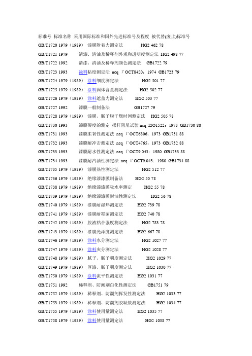
标准号标准名称采用国际标准和国外先进标准号及程度被代替(废止)标准号GB/T1720-1979(1989)漆膜附着力测定法HG2-462-78GB/T1721-1979 清漆、清油及稀释剂外观和透明度测定法HG2-498-77GB/T1722-1992 清漆、清油及稀释剂颜色测定法GB1722-79GB/T1723-1993 涂料粘度测定法neq ГOCT8420:1974 GB1723-79GB/T1724-1979(1989)涂料细度测定法HG2-501-77GB/T1725-1979(1989)涂料固体含量测定法HG2-502-77GB/T1726-1979(1989)涂料遮盖力测定法HG2-503-77GB/T1727-1992 漆膜一般制备法GB1727-79GB/T1728-1979(1989)漆膜、腻子膜干燥时间测定法HG2-505-78GB/T1730-1993 漆膜硬度的测定摆杆阻尼试验neq ISO1522:1973 GB1730-88 GB/T1731-1993 漆膜柔韧性测定法neq ГOCT6806:1973 GB1731-88GB/T1732-1993 漆膜耐冲击测定法neq ГOCT4765:1973 GB1732-88GB/T1733-1993 漆膜耐水性测定法neq ГOCT9.043:1980 GB1733-88GB/T1734-1993 漆膜耐汽油性测定法neq ГOCT9.043:1980 GB1734-88GB/T1735-1979(1989)漆膜热性测定法HG2-512-77GB/T1736-1979(1989)绝缘漆漆膜制备法HG2-50-78GB/T1738-1979(1989)绝缘漆漆膜吸水率测定HG2-55-78GB/T1739-1979(1989)绝缘漆漆膜耐油性测定法HG2-56-78GB/T1740-1979(1989)漆膜耐湿热测定法HG2-739-78GB/T1741-1979(1989)漆膜耐霉菌测定法HG2-740-78GB/T1742-1979(1989)胶液粘合强度测定法HG2-783-78GB/T1743-1979(1989)漆膜光泽度测定法HG2-667-78GB/T1746-1979(1989)涂料水分测定法HG2-1027-77GB/T1747-1979(1989)涂料灰分测定法HG2-1028-77GB/T1748-1979(1989)腻子、腻子稠度测定法HG2-1029-77GB/T1749-1979(1989)厚漆、腻子稠度测定法HG2-1030-77GB/T1750-1979(1989)涂料流平性测定法HG2-1031-77GB/T1751-1992 稀释剂、防潮剂白化性测定法GB1751-79GB/T1752-1979(1989)稀释剂、防潮剂挥发性测定法HG2-1033-77GB/T1753-1979(1989)稀释剂、防潮剂胶凝数测定法HG2-1034-77GB/T1755-1979(1989)涂料使用量测定法HG2-1035-77GB/T1758-1979(1989)涂料使用量测定法HG2-1038-77GB/T1761-1979(1989)漆膜抗污气性测定法HG2-1042-77GB/T1762-1979(1989)漆膜回粘性测定法GB1762-79GB/T1763-1979(19890 漆膜耐化学试剂性测定法HG2-1144-78GB/T1964-1979(1989)漆膜厚度测定法HG2-1145-78GB/T1965-1979(1989)测定耐湿热、耐盐雾、耐候性(人工加速)的漆膜制备法HG2-1 146-78GB/T1766-1995 色漆和清漆、涂层老化的评级方法neq ISO4682:1980 GB/T1766-79(89)GB/T9277.1~9277.5-88GB/T1768-1979(1989)漆膜耐磨性测定法HG2-1174-78GB/T1769-1979(1989)漆膜磨光性测定法HG2-1183-78GB/T1770-1979(1989)底漆、腻子膜打磨测定法HG2-1184-78GB/T1771-1991 色漆和清漆耐中性盐雾性能的测定neq ISO7253:1984 GB1771-79 GB/T1865-1997 色漆和清漆人工气候老化和人工辐射曝露(滤过的氙弧辐射)neq I SO11341:1994 GB/T1865-80(89)GB/T2705-1992 涂料产品分类、命名和型号GB2705-81GB/T3181-1995 漆膜颜色标准GB/T3181-82(89)GB3186-1982(1989)涂料产品的取样neq ISO1512:1974等GB/T5206.1-1985 色漆和清漆词汇第一部分通用术语neq ISO4618/1:1978GB/T5206.2-1986 色漆和清漆词汇第二部分树脂术语neq ISO/DIS4618/3.2GB/T5206.3-1986 色漆和清漆词汇第三部分颜料术语GB/T5206.4-1989 色漆和清漆词汇第四部分涂料及涂膜物化性能术语neq ISO4618/1:1984GB/T5206.5-1991 色漆和清漆词汇第一部分涂料及涂膜病态术语neq ISO4618/2:1984GB/T5207-1985 涂料闪火试验确定危险等级快速平衡法neq ISO3680:1983 GB/T5208-1985 涂料闪点测定法快速平衡法neq ISO3679:1983GB/T5209-1985 色漆和清漆耐水性的测定浸水法neq ISO1521:1973 GB/T5210-1985 涂层附着力的测定法拉开法neq ISO4624:1978GB/T6739-1996 涂膜硬度铅笔测定法eqv IJSK5400:1990GB/T6740-1986 涂料挥发无和不挥发物是测定eqv ISO3251:1974GB/T6741-1986 均匀漆膜制备法(旋转涂漆器法)GB/T6742-1986 漆膜弯曲试验(圆柱轴) neq ISO1519:1972GB/T6743-1986 色漆和清漆用漆基酸值的测定法eqv ISO3682:1983GB/T6744-1986 色漆和清漆用漆基皂化值的测定法eqv ISO3681:1983 GB/T6749-1997 漆膜颜色表示方法GB/T674986GB/T6750-1986 色漆和清漆密度的测定eqv ISO2811:1974 GB1756-7 9GB/T6751-1986 色漆和清漆挥发物和不挥发物的测定eqv ISO1515:1973GB/T6752-1986 色漆和清漆容器中物质量的测定eqv ISO3232:1974GB/T6753.1-1986 涂料研磨细度的测定eqv ISO5124:1983GB/T6753.2-1986 涂料表面干燥试验小玻璃球法eqv ISO1517:1973GB/T6753.3-1986 涂料贮存稳定性试验方法neq ASTM D1849:1980 GB/T6753.4-1998 涂料流出时间的测定ISO流量杯法eqv ISO2431:1984 G B/T6753.4-86GB/T6753.5-1986 涂料及有关产品闪点测定法闭口杯平衡法eqv ISO1523:198 3GB/T6753.6-1986 涂料产品的大面积刷涂试法eqv ISO/TR3172:1974GB/T9263-1988 防滑甲板漆防滑性的测定eqv NF J17-095GB/T9264-1988 色漆流挂性的测定eqv FED-STD-141B方法4494GB/T9265-1988 建筑涂料涂层耐碱性的测定neq JISK5663:1981GB/T9266-1988 建筑涂料涂层耐洗刷性的测定neq JISK1653:1981GB/T9267-1988 乳胶漆用乳液最低成膜温度的测定neq JISK2115:1976 GB/T9268-1988 乳胶漆耐冻融性的测定neq ASTM D2243:1982GB/T9269-1988 建筑涂料粘度的测定斯托默粘度计法GB/T9270-1988 浅色漆对比率的测定(聚酯膜法)eqv ISO3906:1980 GB/T9271-1988 色漆和清漆标准试板eqv ISO1514:1984GB/T9272-1988 液态涂料内不挥发分容量的测定eqv ISO3233:1984GB/T9273-1988 漆膜无印痕试验eqv ISO3678:1976GB/T9274-1988 色漆和清漆耐液体介质的测定eqv ISO2812:1974GB/T9275-1988 色漆和清漆巴克霍尔兹压痕试验eqv ISO2815:1974GB/T9276-1996 涂层自然气候曝露试验方法eqv ISO2810 GB/T9276-88 GB /T1767-79(88)GB/T9278-1988 涂料试样状态调节和试验的湿温度eqv ISO3270:1984GB/T9279-1988 色漆和清漆划痕试验eqv ISO1518:1973GB/T9280-1988 色漆和清漆耐码垛性试验eqv ISO4622:1980GB/T9281-1988 色漆和清漆用漆基加氏颜色等级评定透明液体颜色eqv ISO4630:1981GB/T9282-1988 透明液体以铂-钴等级评定颜色eqv ISO6271:1981GB/T9283-1988 涂料用有机溶剂沸程的测定eqv ISO4626:1980GB/T9284-1988 色漆和清漆用漆基软化点的测定环球法eqv ISO4625:1980 GB9285-1988 色漆和清漆用原材料取样eqv ISO842:1984GB/T9286-1988 色漆和清漆漆膜的划格试验eqv ISO2409:1972 GB/T9286-88GB/T9750-1988 涂料产品包装标志GB9750-88GB/T9751-1988 涂料在高剪切速率下粘度的测定neq ISO2884:1974GB/T9752-1988 涂料及有关产品/不闪试验闭口杯平衡法neq ISO1516:1981 GB/T9753-1988 色漆和清漆杯突试验neq ISO1520:1973GB/T9754-1988 色漆和清漆不含金属颜料的色漆漆膜之20°、60°和85°镜面光泽的测定neq ISO2813:1978GB/T9758.1-1988 色漆和清漆"可溶性"金属含量的测定第一部分铅含量的测定火焰原子吸收光谱法和双硫腙分光光度法idt ISO3856/1:1984GB/T9758.2-1988 色漆和清漆"可溶性"金属含量的测定第二部分锑含量的测定火焰原子吸收光谱法和若丹明B分光光度法idt ISO3856/2:1984GB/T9758.3-1988 色漆和清漆"可溶性"金属含量的测定第三部分钡含量的测定火焰原子发射光谱法idt ISO3856/3:1984GB/T9758.4-1988 色漆和清漆"可溶性"金属含量的测定第四部分镉含量的测定火焰原子吸收光谱法和极谱法idt ISO3856/4:1984GB/T9758.5-1988 色漆和清漆"可溶性"金属含量的测定第五部分液体色漆的颜料部分或粉末状漆中六价铬含量的测定二苯卡巴肼分光光度法idt ISO3856/5:1984GB/T9758.6-1988 色漆和清漆"可溶性"金属含量的测定第六部分色漆的液体部分中铬含量的测定火焰原子吸收光谱法idt ISO3856/6:1984GB/T9758.7-1988 色漆和清漆"可溶性"金属含量的测定第七部分色漆的颜料部分和水稀释漆的液体部分的汞含量的测定无焰原子吸收光谱法idt ISO3856/7:1984GB9760-1988 色漆和清漆液体或粉末状色漆中酸萃取物的制备idt ISO6713:1984 GB/T9761-1988 色漆和清漆色漆的目视比色eqv ISO3688:1976GB/T10834-1989 船舶漆耐盐水性测定盐水和热盐水浸泡法GB/T11185-1989 漆膜弯曲试验(锥形轴)eqv ISO6860:1984GB/T11186.1-1989 涂膜颜色的测量方法第一部分原理eqv ISO7724/1:1984GB/T11186.2-1989 涂膜颜色的测量方法第二部分颜色测量eqv ISO7724/2:1984GB/T11186.3-1989 涂膜颜色的测量方法第三部分色差计量eqv ISO7724/3:1984 GB/T11189.1-1989 非金属材料曝露试验用的有水和无水光曝露设备(氙弧型)及实施方法eqv ASTM G26:1983GB/T11189.2-1989 非金属材料曝露试验用的有水和无水光曝露设备(碳弧型)及实施方法eqv ASTM G23:1981GB/T11190-1989 色漆、清漆、喷漆及有关产品的光-水光曝露设备(碳弧型)及实施方法eqv ASTM D822:1980GB/T12989-1991 色漆和清漆术语词条对照表eqv ISO4617/1~4:1986GB/T13452.1-1992 色漆和清漆总铅含量的测定火焰原子吸收光谱法eqv ISO6503:198 4GB/T13452.2-1992 色漆和清漆漆膜厚度的测定eqv ISO2808:1974GB/T13452.3-1992 色漆和清漆遮盖力的测定第一部分:适用于白色和浅色漆的kubel-ka-Munk法eqv ISO6504/1:1983GB/T13452.4-1992 色漆和清漆钢铁表面上和丝状腐蚀试验eqv ISO4603:1984GB/T13491-1992 涂料产品包装通则GB/T13893-1992 色漆和清漆耐湿性的测定连续冷凝法eqv ISO6270:1980 GB/T14826-1993 色漆涂层粉化程度的册方法及评定neq ASTM D 659:198 0GB/T15957-1995 大气环境腐蚀性分类GB/T16592-1996 粉末涂料烘烤时质量损失的测定idt ISO8130.7-1992GB/T16995-1997 热固性粉末涂料在给定温度下胶化时间的测定neq ISO8130.6-1992 HG/T2458-1993 涂料产品检验、运输和贮存通则HG/T2881-1997 脱漆剂脱漆效率测定法GB/T1745-79(89)HG/T2882-1997 催干剂的催干性能测定法GB/T1744-79(89)HG/T2997-1979(1997)蒙布涂漆后重量增加测定法GB/T1754-79(89)HG/T2998-1979(1997)涂布漆涂刷性测定法GB1757-79(89)HG/T2999-1979(1997)蒙布涂漆后收缩率测定法GB1759-79(89)HG/T3000-1979(1997)蒙布涂漆后抗张强度测定法GB1760-79(89)HG2-57-1980(1985)绝缘漆漆膜击穿强度测定法HG2-57-64HG2-59-1978 绝缘漆漆膜表面电阻及体积电阻系数测定法HG2-59-64HG2-60-1980 绝缘漆耐电弧性测定法HG2-60-64HG2-784-1979 铝及其合金底材电泳漆膜制备法(试行)HG/T2-1046-1977 电泳漆漆膜制备法HG/T2-1047-1977(1985)电泳漆电导率测定法HG/T2-1048-1977(1985)电泳漆泳透力测定法HG/T2-1049-1977(1985)电泳漆库仑效率测定法HG/T2-1050-1977(1985)电泳漆沉积量测定法HG/T2-1198-1977(1985)电泳漆泳透力测定法(钢管法)HG/T2-1608-1985 油脂皂化值测定法化暂2031-57HG/T2-1609-1985 油脂不皂化物含量测定法化暂2032-57 HG/T2-1610-1985 油脂碘价测定法化暂2033-57HG/T2-1611-1985 漆膜耐油性测定法化暂2017-57 HG/T2-1612-1985 漆膜吸水率测定法化暂2020-57。
interrtaco 快换接头样本

公司介绍THE COMP ANYI ntertraco is a fully integrated manufacturer of hydraulic hosefittings, quick disconnect couplings and hydraulic valves.Our broad range of components has been designed and isconstantly developed to service the most diversified customer'sneeds in hydraulic, chemical, off-shore, agricultural andindustrial applications.The market scope, experience and distribution of our productsmake them the right choice in today's demanding market.The subject brochure presents our range of quick disconnectcouplings, swivel joints and in-line valves. Array The catalogue is designed for our customers as a workingtool to assist them in chosing and selecting the correct productfor their specific application.If there are applications outside of the standard range, wecan work jointly with our customers to develope andmanufacture specific products to meet their requirements.Intertraco是一家集液压软管配件、快速接头和液压阀的完整集成生产商。
1防爆设备标准链接清单

:2017,MOD
GB3836.17-2007
46.
GB/T
3836.18-2017
爆炸性环境第18部分:本质安全系统
IEC60079-25
:2010,MOD
GB383668-2010
47.
GB3836.19-2010
爆炸性环境第19部分:现场总线本质安全概念(FISCO)
IEC60079-27
GB25286.1
-2010
27.
GB∕T1336∙1977
防爆电气设备制造检验规程
28.
GB∕T2900.35-2008
电工术语爆炸性环境用设备
IEC60050
-426,1DT
PPT
29.
GB3836.1-2010
爆炸性气体环境用电气设备第1部分:通用要求
IEC60079-0
:2007,MOD
GB38366-2000
IEC60079-6
2015,MOD
GB383662004
35.
GB/T3836.7-2017
爆炸性环境第7部分:由充砂型“q”保护的设备
IEC60079-5
:2015,MOD
GB3836.7-2004
36.
GB3836.8-2014
爆炸性环境第8部分:由“n”型保护的设备
IEC60079-15来自:2001JDTmaintenanceofdetectorsforf1ammab1egasesandoxygen
19.
BSEN60079-29-3
-2014
Exp1osiveatmospheres.Gasdetectors-Guidanceonfunctiona1safetyoffixedgasdetectionsystems
尿毒症毒素 -1-27 杨锋

杨锋
淮南朝阳肾内科
尿毒症毒素
Piorry、 Heritier
1840年
尿毒症概念
200余 种毒素
尿毒症症状
细胞与组织器 官结构损伤与
功能失常
机体代谢紊乱
尿毒症毒素
尿毒毒素蓄积
肾功能
代谢性酸中毒、体液超
其 负荷、电解质紊乱、蛋
它 因 素
白质代谢终末产物蓄积、 营养不良、激素失衡
净产生
氧化应激、微炎 症状态、蛋白质
动脉硬化 腹膜超滤过功丧失
炎症反应
尿毒症毒素
晚期蛋白质氧化产物 Advanced oxidation protein products,AOPP
活性氧 ROS
氨基酸残基
酪氨酸
氧化现象
双酪氨酸
蛋白质聚集 交联
尿毒症毒素
同型半胱氨酸 homocysteine
高同型半胱氨酸血症指血浆中同型半胱氨酸水平高于15mM
治疗包括叶酸、或联合应用维生素B6和/或维生素B12 补充叶酸的潜在效应就是使S腺苷甲硫氨酸(蛋氨 酸)/S腺苷高半胱氨酸比值正常化 S腺苷高半胱氨酸是一种毒性极强的化合物,与S腺 苷甲硫氨酸进行竞争,从而抑制甲基转移酶活性
尿毒症毒素
补体 Activated compliments
心血管疾病是终末期肾病的主要死亡原因
修饰
尿毒症发病
尿毒症毒素
尿毒症毒素的特征:
潴留于尿毒症患者体内而且其浓度水平明显高于正常人 有明确的理化性质与分子结构 在体内潴留某种溶质与特异的尿毒症症征明确相关 采用尿毒症时其体内相应的浓度可以在动物模型再现尿 毒症症征,或组织细胞损伤现象 清除体内该物质时可以减轻或缓解尿毒症症征
发那科参数(详细)
四轴参数说明N0000 00000010 (#2=0公制输入单位,=1为英制,这里只设公英制输入单位,机床公英制由1001#0决定;#1=1输出ISO代码,=0为EIA代码)N0001 P 00000000 #1=0纸带格式为标准格式N0002 P 00000000 (手动回零:#7 =0参考点未建立,利用减速挡块,已建立,快速定位到参考点(1005#3=1有效),#7=1都利用减速挡块回零)N0012 A1 P 00000000 A2 P 00000000 A3 P 00000000 A4 P 00000000 #0各轴镜像设定:=0关断,=1开通..........2..........N3153 P 3 ............3..........N3154 P 4 ............4..........N3201 P 01000000 #2=0当登录的程序与已登录的程序号相同时报警,=1替换原来程序;#3=0当用ISO代码输出程序号的地址O时输出[:],=1输出[O];#6=1:程序登录时,对M02、M30或M99的程序段设定不视为程序结束,=0视为登录结束;#5若#6设0该位设0视M99为程序登录结束,设1不视为结束N3202 #0=0:不禁止程序号8000~8999号子程序的编辑;#4=1:禁止程序号9000~9999号子程序的编辑;#6=0:检索被保护程序的程序号时无效N3203 #5=0当MDI方式开始运行后,不禁止程序的编辑;#6=0在MDI执行完后不删除已执行程序,除非由%输入;#7=0:按复位不删除MDI方式中编辑的程序N3204 P 00000100 #2:显示C-EXT扩展编辑功能N3205 #0:在显示或输出程序时,对程序内注释中的冒号:=0变成O后再显示或输出,=1原封不动输出或显示[:] N3210 保护9000号组程序的口令N3211 解除9000号程序口令,设定与3210中值一致皆解除N3216 自动插入顺序号的增量值0000#5为1有效N3290 P 00000000 在MDI下刀具偏置、工件原点偏置、宏变量输入都不禁止........2..............N3743 P 8000 #..........3..............N3744 P 8000 #..........4..............N4099 A1 P 0 #默认N4100 A1 P 760 根据马达型号N4101 A1 P 100 根据马达型号N4102 A1 P 1134 根据马达型号N4103 A1 P 1134 根据马达型号N4104 A1 P 2000 根据马达型号N4105 A1 P 2000 根据马达型号N4106 A1 P 1500 根据马达型号N4107 A1 P 1500 根据马达型号N4108 A1 P 500 根据马达型号N4109 A1 P 10 根据马达型号N4110 A1 P 984 根据马达型号N4111 A1 P 28 根据马达型号N4112 A1 P 533 根据马达型号N4113 A1 P 140 根据马达型号N4114 A1 P 12 根据马达型号N4115 A1 P 7 根据马达型号N4116 A1 P 100 根据马达型号N4117 A1 P 20 根据马达型号N4118 A1 P 30 根据马达型号N4119 A1 P 0 默认N4120 A1 P 40 根据马达型号N4121 A1 P 5 默认N4122 A1 P 0 默认N4123 A1 P 30 默认N4124 A1 P 0 默认N4125 A1 P 0 默认100,自动操作定时器设置N4126 A1 P 0 默认1000,自动操作速度指令N4127 A1 P 144 根据马达信号N4129 A1 P 0 根据马达信号N4130 A1 P 0 根据马达信号N4131 A1 P 0 默认N4132 A1 P 0 默认N4133 A1 P 114 #主轴电机代码N4135 A1 P 0 默认N4136 A1 P 0 #低速时正常旋转马达电压 (若为0与4083相同)N4166 A1 P 0 #低速时再生能源极限(若为0与4080相同)N4136~N4174 都是默认或根据马达型号决定N4191 A1 P 00000111N4312 A1 P 0 #位置编码器方式定向接近结束时检测电平N4176~N4351 为第二主轴,略// 有关刀补参数N5001 #0选择刀具长度补偿类型:=0由#1决定类型A或B,=1为类型C;#1=0类型A,即与平面无关,通常为Z轴,=1与指定平面G17、18、19垂直的轴;#2=0刀具长度补偿用H代码,刀长半径补偿C用D代码,刀长位置偏置由#5决定,=1都由H代码指定(刀具半径补偿B时设1);#5刀具位置偏置G45~48的偏置号地址:=0用D代码指定,=1用H代码指令N5003 #6=0利用复位取消刀具长度补偿的补偿量,=1不取消N5004 #2刀具半径补偿量:=0由半径值设定,=1由直径值设定N5008 P 00000101 #0=1:不进行刀具半径C的干涉检查,=0进行;#1=0在上述干涉检查中,编程移动方向和偏置移动方向相差90~270度时报警;#2=1刀具半径补偿C中拐角圆弧功能G39有效// 有关固定循环参数N5101 #0使用钻削固定循环的钻孔轴:=0通常位Z轴,=1由程序选择轴;#1=0 G81指定为钻孔用固定循环;#4、5设定钻孔固定循环G76、87退刀轴及方向(见书);#6=0攻丝循环G84、74中,主轴回转换向时,在输出M03或M04之前输出M05,=1不输出M05;#7=0在G76、87中,主轴定位之前输出M05,=1不输出N5103 #1在G73中,不用Q指定每次切入量时或指令Q0时:=0不报警,=1报警N5114 P 1000 高速深孔循环G73的退刀量 1mmN5115 P 1000 固定循环G83的留空量 1mm// 有关刚性攻丝参数(很多参数不准)轮比:=0不用任意齿轮比(3706上设定齿轮比),=1用任意齿轮比(5224、5231~5234设定);#2=0用刚性解除指令G80、01组G码或复位等解除刚性状态要等刚性攻丝信号RGTAP变为0才可;#5=0刚性攻丝为高速深孔攻丝循环,=1一般刚性攻丝N5201 P 00000001 #0=1进行刚性攻丝的平滑处理;#2=0刚性攻丝中切削时间常数进刀退刀使用同样参数5261~5264,=1不同样,进刀5261~5264,退刀5271~5274N5202 P 00000001 #0=1刚性攻丝开始,主轴进行准停;N5204 P 00000000 #0=0诊断画面455~457显示刚性攻丝同步误差,=1显示主轴和攻丝轴误差量的差452、453N5210 P 29 刚性攻丝方式指令的M代码N5211 P 10 刚性攻丝退刀时的倍率值5200#4=1有效5200#3=1,设定单位为10%N5214 P 10000 深孔攻丝循环时回退量和留空量 10mmN5221 P 10 主轴侧齿轮齿数1档N5222 P 10 主轴侧齿轮齿数2档N5223 P 10 主轴侧齿轮齿数3档N5231 P 10 编码器侧齿轮齿数1档N5232 P 10 编码器侧齿轮齿数2档N5233 P 10 编码器侧齿轮齿数3档N5241 P 3000 刚性攻丝主轴最高转速1档N5242 P 3000 刚性攻丝主轴最高转速2档N5243 P 3000 刚性攻丝主轴最高转速3档N5261 P 1000 主轴和攻丝轴直线加减速时间常数1档N5262 P 1000 主轴和攻丝轴直线加减速时间常数2档N5263 P 1000 主轴和攻丝轴直线加减速时间常数3档N5271 P 1000 退刀时主轴和攻丝轴直线加减速时间常数1档N5272 P 1000 退刀时主轴和攻丝轴直线加减速时间常数2档N5273 P 1000 退刀时主轴和攻丝轴直线加减速时间常数3档N5280 P 3000 刚性攻丝时主轴和攻丝轴控制回路增益(各齿轮通用)N5281 P 3000 刚性攻丝时主轴和攻丝轴控制回路增益(1档)N5282 P 3000 刚性攻丝时主轴和攻丝轴控制回路增益(2档)N5283 P 3000 刚性攻丝时主轴和攻丝轴控制回路增益(3档)N5292 P 0 刚性攻丝时主轴控制回路增益(2档)N5293 P 0 刚性攻丝时主轴控制回路增益(3档)N5300 P 20 刚性攻丝时攻丝轴到位宽度N5301 P 20 刚性攻丝时主轴到位宽度N5310 P 10000 刚性攻丝时攻丝轴移动位置偏差量的极限值N5311 P 10000 刚性攻丝时主轴移动位置偏差量的极限值N5312 P 500 刚性攻丝时攻丝轴停止时位置偏差量的极限值N5313 P 550 刚性攻丝时主轴停止时位置偏差量的极限值// 有关缩放/坐标旋转的参数N5400 P #0坐标旋转的旋转角度指令R:=0用绝对坐标指令,=1用G90/G91指令;#6=1各轴缩放镜像有效P指令缩放倍率;#7=1缩放倍率单位单位N5401 A1 P 00000001 A2 P 00000001 A3 P 00000001 A4 P 0000001 #0=1分别指定各轴缩放有效N5410 P 0 坐标旋转中程序无旋转角度指令时使用的旋转角度N5411 P 1000 程序无缩放倍率指令时使用的倍率1倍N5421 A1 P 9 A2 P 9 A3 P 9 A4 P 9 各轴缩放倍率9倍// 有关分度工作台分度的参数N5500 P 00000000N5511 P 0N5512 P 0// 有关用户宏程序参数N6000 #0在非G66(宏调用)中指令G67(取消宏调用)指令:=0报警,=1无视;#5=0宏程式中不使用单程序段停止N6001 #3用户宏程序公共变量输出:=0输出#500号组公共变量,=1输出#100和#500号组公共变量;#5用T代码:0不可调用宏程序(子程序),1可以;#6按复位后,宏公共变量#100~#199:=0清空,=1不清除;#7宏局部变量#1~33按复位后:=0清空,=1不清除N6003 宏程序中断有关参数(见书)N6004 #0=0,ATAN结果0~360度,ASIN结果270~90度,=1ATAN-180~180度,ASIN-90~90度N6030 调用外部文件M代码,默认M198N6033 使用户宏程序中断有效的M代码,默认M96N6034 使用户宏程序中断无效的M代码,默认M97N6071 P 0 HC6350无9001宏程序N6071~6079 调用程序号9001~9009子程序的M代码N6080~6089 调用程序号9020~9029用户宏程序的M代码// 有关运转时间、零件数显示的参数//有关刀具寿命管理的参数N6800 #7与M06同一程序段的T代码:=0视为上一把刀具的刀具号,=1视为下一把刀具的刀具号// 有关手动/自动运行的参数N7001 #0手动介入,返回功能:=0无效,=1有效// 有关手轮进给\中断的参数N7102 #0各轴移动方向与手轮回转方向:=0相同,=1相反N7110 P 3 设定使用手轮台数N7113 P 50 手动控制进给倍率m 如手轮*50档N7114 P 100 手动控制进给倍率n 如手轮*100档N7117 P 1 手轮进给容许滑移量// 有关软操作面板参数N7200 使能软操作面板有关参数N7220 P 72 软操作面板通用开关名称N7221 P 78N7222 P 68N7223 P 76N7224 P 32N7225 P 73N7226 P 78N7227 P 84N7228 P 68N7229 P 79N7230 P 79N7231 P 82N7232 P 32N7234 P 66N7235 P 75N7236 P 80N7237 P 79N7238 P 87N7239 P 69N7240 P 82N7241 P 79N7242 P 70N7243 P 70N7276 P 82N7277 P 83N7278 P 84N7279 P 32N7280 P 77N7281 P 65N7282 P 71N7283 P 32// 有关程序再开始、加工返回再开始的参数N7300 #6当程序再开始时检索出要再加工的程序后,移动到再开始加工的位置前输出代码:=0输出最后的M、S、T、B代码,=1输出全部M代码和最后S、T、B代码(#7=1有效);#7决定#6:=0不输出M、S、T、B代码,=1输出;N7310 各轴以空运行速度移动到再开始位置的移动顺序,设1先移// 有关PMC轴参数N8001~8028 见书说明// 系统基本功能参数参数N8130 P 4 总控制轴数N8131 P 00000001 #0=1使用手轮进给N8132 P 00110000 #0=0不使用刀具寿命管理;#3=0不使用分度工作台分度;#4=1使用小口径深孔钻削循环;#5=1使用缩放(#4、5不能同时为1)!!现在机床都为1,改之!N8134 P 00000001 #0=1使用图形对话功能N8701 #2由PMC窗口改变的参数,在自动运行中是否有效N8900 P 00000001N8901 #0=0进行风扇电机异常检测,出现过热报警// 有关系统保密参数N9900 P 4N9901 P 0N9920 P 00111011N9921 P 01000110N9922 PN9923 PN9924 P 00111111N9925 P 00100000N9926 P 01100000N9927 P 01010000N9928 PN9929 P 00001111N9930 P 00111111N9931 PN9932 P 01001111N9933 PN9934 P 01010000N9935 PN9936 PN9937 P 00110011N9940 P 00000100N9941 P 00000101N9942 P 00000101N9943 PN9945 P 00010000 N9946 P 00000101 N9952 P 00000101 N9953 PN9962 P 00000100 N9965 P 00000100 N9972 PN9976 P。
CM3212-02DE,CM3202-02DE,CM3212-02DE,CM3202-02DE, 规格书,Datasheet 资料
The CM3202−02 is available in a space saving WDFN8 surface mount packages. Low thermal resistance allows them to withstand high power dissipation at 85°C ambient. The CM3202−02 can operate over the industrial ambient temperature range of –40°C to 85°C.
†For information on tape and reel specifications, including part orientation and tape sizes, please refer to our Tape and Reel Packaging Specification Brochure, BRD8011/D.
CM3202-02
DDR VDDQ and VTT Termination Voltage Regulator
Product Description
The CM3202−02 is a dual−output low noise linear regulator designed to meet SSTL−2 and SSTL−3 specifications for DDR−SDRAM VDDQ supply and termination voltage VTT supply. With integrated power MOSFETs the CM3202−02 can source up to 2 A of VDDQ continuous current, and source or sink up to 2 A VTT continuous current. The typical dropout voltage for VDDQ is 500 mV at 2 A load current.
长用卡套配件型号
充油
高压管线处,也可用在震动工况 下使用
10mm 双卡套 该型号球阀通径为 6.4mm,PTFE 填料,阀体为不 锈钢材质,最大工作压力为 6000psi.
售气机侧壁加气枪气源启闭 用,常用设计为 10mm 带塑料把 手柄球阀。
选型说明
主要用途
英制接头表示方法为将 1 英 寸 16 等分。如 DU-8 代表 1/2 ″直通,DL-12 代表 3/4″弯 头,DT-24 代表 1 1/2″卡套 三通. 设计为 25mm 公制管线的直
通接头需要到 DU-25M. 材质默认为 SS316.
两种不同的管线连接需用变 径接头(Reducing union). 如将 1/2″管线转换为 12mm 管线 就需要用到变径直通.序源自名称卡套直通1
union
卡套弯头
2
Union elbow 卡套三通
3
Union tee
图形
DK-Lok CNG 加气站常用料单
常用型号
DU-4 (1/4″卡套) DU-8 (1/2 卡套″) DU-12 (3/4″卡套) DU -16 (1″卡套) DU -24 (1 1/2″卡套) DUR 12-8 (1/2″-3/4″卡套) DUR 16-8 (1/2″-1″卡套)
V66-MF-8N (1/2″NPT F)
V66-D-8T (1/2″卡套)
V86A 耐受压力达 10000psi, V86B,V86C 可达 6000psi. ①:如为本体卡套球阀为 H, 内螺纹为 F,外螺纹为 M. ②:对应尺寸,如 1/2″代号 为“8”. ③:卡套对应 TPC(填料为 PCTFE),螺纹对应 NPC. 该系列球阀还可选装气动执 行装置.
LiteonSales光宝光耦介绍
Private & Confidential
OCS Products Lineup
Optocouplers Solutions Division (OSD)
Optocouplers
Product Features : Halogen Free solutions
Private & Confidential
Optocouplers packages types
Private & Confidential
Optocouplers Characteristics
• Viso: isolation voltage (between input and output) – The maximum sustainable voltage between input and output – The Viso of DIP optocouplers (4-pin, 6-pin, 8-pin or 16-pin) is 5000 volts – Safety concerned
300 series
(4-pin MFP)
New !
200 series
(SO8 )
700 series(6-pin DIP) *4N / CNY xx / 700 •MOC (Opoto-Triac )
DC input, phototransistor ( Opoto-darlington) output DC input, IC output AC input, phototransistor output AC input, optot-darlington transistor output
- 1、下载文档前请自行甄别文档内容的完整性,平台不提供额外的编辑、内容补充、找答案等附加服务。
- 2、"仅部分预览"的文档,不可在线预览部分如存在完整性等问题,可反馈申请退款(可完整预览的文档不适用该条件!)。
- 3、如文档侵犯您的权益,请联系客服反馈,我们会尽快为您处理(人工客服工作时间:9:00-18:30)。
ReferencenumberISO7241-2:2000(E)
©ISO2000
INTERNATIONALSTANDARDISO
7241-2
Secondedition2000-03-15
Hydraulicfluidpower—Quick-actioncouplings—
Part2:Testmethods
Transmissionshydrauliques—Raccordsrapides—Partie2:Méthodesd'essaiISO7241-2:2000(E)PDFdisclaimerThisPDFfilemaycontainembeddedtypefaces.InaccordancewithAdobe'slicensingpolicy,thisfilemaybeprintedorviewedbutshallnotbeeditedunlessthetypefaceswhichareembeddedarelicensedtoandinstalledonthecomputerperformingtheediting.Indownloadingthisfile,partiesacceptthereintheresponsibilityofnotinfringingAdobe'slicensingpolicy.TheISOCentralSecretariatacceptsnoliabilityinthisarea.
AdobeisatrademarkofAdobeSystemsIncorporated.DetailsofthesoftwareproductsusedtocreatethisPDFfilecanbefoundintheGeneralInforelativetothefile;thePDF-creationparameterswereoptimizedforprinting.EverycarehasbeentakentoensurethatthefileissuitableforusebyISOmemberbodies.Intheunlikelyeventthataproblemrelatingtoitisfound,pleaseinformtheCentralSecretariatattheaddressgivenbelow.
©ISO2000Allrightsreserved.Unlessotherwisespecified,nopartofthispublicationmaybereproducedorutilizedinanyformorbyanymeans,electronicormechanical,includingphotocopyingandmicrofilm,withoutpermissioninwritingfromeitherISOattheaddressbeloworISO'smemberbodyinthecountryoftherequester.
ISOcopyrightofficeCasepostale56·CH-1211Geneva20Tel.+41227490111Fax+41227341079E-mailcopyright@iso.chWebwww.iso.ch
PrintedinSwitzerland
ii©ISO2000–AllrightsreservedISO7241-2:2000(E)©ISO2000–AllrightsreservediiiContentsPage
Foreword......................................................................................................................................................................vIntroduction................................................................................................................................................................vi1Scope..............................................................................................................................................................12Normativereferences....................................................................................................................................13Termsanddefinitions...................................................................................................................................14Selectionandexaminationoftestsamples................................................................................................25Testapparatus...............................................................................................................................................26Testconditions..............................................................................................................................................27Connectforcetest.........................................................................................................................................28Disconnectforcetest....................................................................................................................................29Leakagetest...................................................................................................................................................39.1Lowpressure,coupled..................................................................................................................................39.2Lowpressure,uncoupled(valvedonly)......................................................................................................49.3Maximumoperatingpressure,coupled.......................................................................................................59.4Maximumoperatingpressure,uncoupled(valvedonly)...........................................................................5
10Extremetemperaturetest.............................................................................................................................510.1Maximumoperatingtemperatureexposure,coupled................................................................................510.2Maximumoperatingtemperatureexposure,uncoupled(valvedonly)....................................................510.3Maximumoperatingtemperatureservice,coupled....................................................................................510.4Maximumoperatingtemperatureservice,uncoupled(valvedonly)........................................................610.5Minimumoperatingtemperature,coupled..................................................................................................610.6Minimumoperatingtemperature,uncoupled(valvedonly)......................................................................6