隧道外文翻译
基于隧道和上部结构开挖的分析外文翻译
毕业设计(论文)外文翻译题目高速公路连拱隧道施工技术学院土木建筑学院专业土木工程(岩土与地下结构工程)学生学号指导教师1基于隧道和上部结构开挖的分析摘要:非线性有限元法和巧凑八节点元被用于计算隧道开挖引起的地表沉降。
非联动流动法则的修正通用塑性模型用于分析巴西的圣保罗隧道。
弹性行为的线性元用于模拟衬砌。
德黑兰和休斯敦砂上铰接和x 型约束的二层楼建筑也用于研究每个不同深度隧道开挖进程。
结果给出了在二倍直径深度下估测的建筑物与隧道之间的相互作用。
但在三倍直径深度下隧道和上部结构之间没有相互作用。
同时开挖引起的上部结构沉降也增加了。
预测结果与圣保罗隧道上的实测数据一直。
当表土减少时,结构下的预测弹性约束增加。
距离隧道中心五倍直径距离处的沉降几乎为零。
当上部结构在地表时,沉降在隧道中心处和距离中心2.5倍直径之间浮动,不应超出这个范围。
关键词:非联结流动法则,开挖方法,隧道与结构的相互影响,通用塑性力1、引言城市隧道在浅埋下施工要求严格控制地表土沉降。
在地表和隧道中心处的施工造成的沉降会引发一些恶劣影响。
诸如土的非线性行为、压力时间历程、表土深度、隧道直径等因素对地面变形的发展有巨大影响。
最近20年许多研究者试图用有限元法模拟隧道进程。
他们用莫尔库伦准则和冯米斯准则进行二维和三维模拟。
虽然这些模型被广泛的应用,但这些模型对与压力区的独立性、非线性、体积和剪切回应的耦合、约束软化上仍缺乏通用性。
通常变量模型用于计算粘土隧道的沉降。
Stallebrass 用三个表面动态硬化基本模型模拟土行为,其过程用那个与预测隧道在坚硬粘土中施工的联合位移。
卡拉库斯和福威尔用修正剑桥模型来模拟隧道施工过程中的伦敦粘土行为和计量沉降。
通过约束独立的修正剑桥模型来运用有限元法模拟新奥法。
Mroueh和Shahrour将结构的存在当作在隧道施工期间软土隧道和结构连接。
假定完全弹塑性基础关联基于非联结流动法则的莫尔库伦准则。
本文用考虑有限元法的隧道开挖模拟的两步和非联结流动的通用弹性模型补充分析砂行为。
外文翻译-国外巷道掘进施工技术及发展趋势
附录A国外巷道掘进施工技术及发展趋势国外煤矿现代巷道掘进施工方法主要有钻爆法和综合机械化掘进法(简称综掘法)。
岩巷掘进仍采用钻爆法,煤和半煤岩巷广泛采用掘进机,英国采用掘进机掘进煤和半煤岩巷的比例已达85%。
综掘法是近二三十年间迅速发展起来的一种先进的巷道掘进技术。
其主要设备是掘进机,它是一种集切割岩石、装载及转运岩渣、降尘等功能为一体的大型高效联合作业机械设备,能实现连续掘进,目前国际先进水平已实现自动控制及离机遥控操作。
1 钻爆破岩掘进50年代,国外已基本实现钻、装、支等工序的单项机械化;60年代以后,主要是改进原有设备,组织平行作业,实现机械化配套作业线;进入70年代以来,自法国的Montabert推出世界第一台实用的液压凿岩机后,液压凿岩机得到迅速的发展与应用。
瑞典Atlas Copco公司于80年代研制推出的三挡式液压凿岩机,因可改变输出冲击能,所以适用于在不同硬度的岩石巷道掘进中钻凿炮眼,从而得到世界各国的重视。
目前,液压凿岩机新产品更新换代时间短,新产品、新型号不断涌现,产品性能向大扭矩、大冲击能和高频率方向发展。
如法国 Eimco Secoma公司生产的RPH200型、RPH400型液压凿岩机早已为HD200型、HD300型所取代。
瑞典 Atlas Copco公司研制COP1238液压凿岩机早已被COP1838型、COP4050型液压凿岩机所取代。
COP1838系列液压凿岩机的功率达到18kW,钻凿比比COP1238高50%,且其内部缓冲装置经过改进,能更好地吸收钎具的反弹与振动。
而COP4050型液压凿岩机的功率更大,它的冲击功率最大可达45kW,深孔凿岩时一般用30kW 的液压凿岩机。
芬兰Tamrock公司研制推出的HL4000型系列液压凿岩机可钻凿孔径达170~230mm、深度达38m的炮眼。
近年来,由于液压凿岩技术的大力发展,形成了钻、装、运、支等机械化配套作业线;法、英、德等相继开发出了一机多用的机组,简化了工作面的作业设备,缩短了机械搬、调、运时间,提高了掘进工效和速度。
模板工程外文翻译
模板工程模板工程,有时被称为模板或铸件,木板或薄膜的建立是用于制造模具并放置初始的湿混凝土进行硬化的时期。
有两种类型的模板工程,即永久和临时模板工程。
永久性模板工程是在对混凝土进行操作后混凝土将保持不变。
这可能是因为曾经无法清除的工作已经完成,或者是由于成品表面材料在第一时间就被用作模板。
临时模板工程是指在混凝土强度达到一定要求时,不再被需要而被移除,移除的操作方式通常被称为拆除。
当发生拆除,模板拆除,然后重用组件的另一部分结构。
这种组件可以重复利用,被称为标准模板工程。
1 模板工程的要求一个好的模板工程应该满足以下要求●模板应该做到牢固到足以安全的承载湿的混凝土的质量和工人使用机器在具体位置将混凝土排入模板时的活荷载和冲击荷载;●它应该是特别防水的以至于它不从混凝土中吸收水分,并且它的收缩和膨胀也应该最低;●模板的样式应该是足够的严格来保持正确的线条和水平防止过度的膨胀或下垂;●部分与部分之间的关节处模板应该足够紧以防止水的损失或混凝土灌浆;●要求完成的混凝土表面是光滑的,纹理的,或有浮露骨料的;●模板样式应该足够牢固和高要求的,这不仅仅是使用,而且也用于处理和拆除,因为永久模板是非常经济的。
●在任何时候进行模板设计和计算具体的倾倒和置换的混凝土的量,可能进行的操作都必须得考虑进去;●尽管它是铸造过程中的最后一道程序,但是模板可以拆除仍然是最重要的;●模板应该尽可能的重用多次,并且考虑初始成本开销和重用次数。
2 简单模板工程施工模板设计必须考虑到各个方面的需求。
模板有两个部分:与混凝土接触的面的部分和支持这个面的支撑部分。
该面背后的支撑可以分为两类:永久和临时。
使用标准形式时他们通常会将该面设置在永久支架上。
它通常是由木材或钢材制造, 但对于塑料和玻璃纤维面临可能加入造型形式的肋骨和角度。
临时支撑包括:道具、横木、托梁、支柱,和所有其他将这种形态稳固并将荷载传到基础结构的支撑。
3 用于模板的材料用于塑造混凝土结构形态的材料包括木材、胶合板、纤维板、塑料、钢铁和铝等其他材料。
云技术和服务中英文对照外文翻译文献
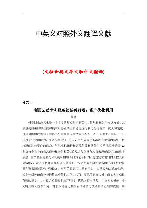
中英文对照外文翻译文献(文档含英文原文和中文翻译)译文:利用云技术和服务的新兴前沿:资产优化利用摘要投资回报最大化是一个主要的焦点对所有公司。
信息被视为手段这样做。
此信息是用来跟踪性能和提高财务业绩主要通过优化利用公司资产。
能力和速度,这是可能的收集信息并将其分发到当前的技术该组织正在不断增加,事实上,有超过了行业的能力,接受和利用它。
今天,生产运营商被淹没在数据的结果一种改进的监控资产的能力。
智能电机保护和智能仪器和条件监控系统经常提供32多块每个设备的信息都与相关的报警。
通常运营商没有装备来理解或行动在这个信息。
生产企业需要充分利用标的物专门为这个目的,通过定位他们的工程人员区域中心。
这些工程师需要配备足够的知识能够理解和接受适当的行动来处理警报和警报通过这些智能设备。
可用的信息可以是有用的,在寻找方法增加生产,减少计划外的维护和最终减少停机时间。
然而,寻找信息在实时,或在实时获得有用的信息,而不花了显着的非生产时间,使数据有用的是一个巨大的挑战。
本文将介绍云技术作为一种获取可视化和报告的经济方法条件为基础的数据。
然后,它将讨论使用云技术,使工程资源与现场数据可通过网络浏览器访问的安全格式技术。
我们将覆盖资产的方法多个云服务的优化和效益飞行员和项目。
当重工业公司在全球范围看,世界级运营实现整体设备效率(OEE)得分百分之91。
从历史上看,石油和天然气行业的滞后,这得分十分以上(Aberdeen 集团“操作风险管理”十月2011)。
OEE是质量的商,可用性和效率得分。
这些,可用性似乎影响了石油和天然气行业的最大程度。
在石油和天然气的可用性得分的根源更深的研究导致旋转资产作为故障的根本原因,在70%的情况下,失去的生产或计划外停机。
鉴于这一行业的关键资产失败的斗争,但有方法,以帮助推动有效性得分较高,以实现经营效率的目标。
.在未来十年中,海上石油储量的追求将涉及复杂的提取方法和海底提取技术的广泛使用。
水利水电毕业设计外文文献翻译

水工建筑物,29卷,9号,1995旋涡隧道溢洪道。
液压操作条件M . A .戈蓝,B. zhivotovskii,我·诺维科娃,V . B .罗季奥诺夫,和NN罗萨娜娃隧道式溢洪道,广泛应用于中、高压液压工程。
因此研究这类溢洪道这是一个重要的和紧迫的任务,帮助在水工建筑中使用这些类型的溢洪道可以帮助制定最佳的和可靠的溢洪道结构。
有鉴于此,我们希望引起读者的注意,基本上是新的概念(即,在配置和操作条件),利用旋涡流溢洪道[1,2,3,4 ]。
一方面,这些类型的溢洪道可能大规模的耗散的动能的流动的尾段。
因此,流量稍涡旋式和轴向流经溢洪道的尾端,不会产生汽蚀损害。
另一方面,在危险的影响下,高流量的流线型面下降超过长度时,最初的尾水管增加的压力在墙上所造成的离心力的影响。
一些结构性的研究隧道溢洪道液压等工程rogunskii,泰瑞,tel'mamskii,和tupolangskii液压工程的基础上存在的不同的经营原则现在已经完成了。
这些结构可能是分为以下基本组:-涡旋式(或所谓的single-vortex型)与光滑溢洪道水流的消能在隧道的长度时的研究的直径和高度的隧道;参看。
图1),而横截面的隧道是圆或近圆其整个长度。
涡旋式溢洪道-与越来越大的能量耗散的旋涡流在较短的长度- <(60——80)高温非圆断面导流洞(马蹄形,方形,三角形),连接到涡室或通过一个耗能(扩大)室(图2)[ 5,6 ]或手段顺利过渡断[ 7];-溢洪道两根或更多互动旋涡流动耗能放电室[ 8 ]或特殊耗能器,被称为“counter-vortex耗能”[ 2,4 ]。
终端部分尾水洞涡流溢洪道可以构造的形式,一个挑斗,消力池,或特殊结构取决于流量的出口从隧道和条件的下游航道。
液压系统用于的流量的尾管可能涉及可以使用overflowtype或自由落体式结构。
涡旋式溢洪道光滑或加速[ 7 ]能量耗散的整个长度的水管道是最简单和最有前途的各类液压结构。
外文翻译--液压冲击锤在伊斯坦布尔地铁工程中的应用

毕业设计外文翻译
表 1
图2 362种冲击锤的频率与效率关系图
一些冲击锤的效率可能略高于100%,这可能是因为一览表数据错误。
经常发生冲击锤内部润滑油外漏的情况,致使输出功率仅为输入功率的70
1.液压冲击锤
2.托架
3.臂栓
4.锤尖
图 5 挖掘机的重量和冲击锤使用质量之间的关系
掘进装置和冲击锤的瞬时力量平衡公式6
0.50h
W <
图 6
图 7
独立研究表明冲击锤净破坏率与岩石精度有紧密关系。
还得出结论,Schmidt冲击锤的回弹力是一项岩石特性的重要指标。
当岩层以岩石质量标出化合时,回弹力与冲击锤净破坏率有明显关系。
液压支架外文翻译
汇报人:XX
01 02 03 04
05
Part架英文简称:hydraulic support 液压支架英文简称简写:HS
液压支架的英文名称是"Hydraulic Support System"。
工作原理:利用高压液体驱动立柱升降,实现对顶板的支撑和防护
液压系统:由泵站、控制阀、管路等组成,实现液体压力的传递和控制
动力来源:通常由乳化液泵站提供高压乳化液作为动力源
工作特点:具有高可靠性、高稳定性和高安全性等特点,是现代化矿井中不可或缺的重要装 备之一
采煤作业:液压支架用于支撑采煤工作面的顶板,保护作业人员和设备安 全。
立柱:jack column 底座:base plate
添加标题
Common Problems of Hydraulic Support and their troubleshooting in English Terminolo gy
添加标题
Failure Diagnos is and Repair of Hydraulic Suppor t in English Termino lo gy
维护: Maintenance
保养:Caring
清洗: Cleaning
检查: Inspection
安装:Installation 调试:Commissioning 运行:Operation 维护:Maintenance
Part Five
准确理解原文含义 语言表达清晰流畅 符合目标语言习惯 保持原文风格和修辞手法
掌握专业术语:熟悉液压支架领域的专业词汇和表达方式,确保翻译准确。 了解语言差异:熟悉中英文在语法、句式和表达习惯上的差异,提高翻译流畅度。 参考权威资料:查阅相关外文资料、文献或产品说明书,获取更准确的翻译参考。 实践锻炼:多进行实际翻译练习,通过不断实践提高翻译水平。
公路双连拱隧道设计与施工
应附图:地质纵剖面图,支护结构设计横剖面图、衬砌结构横剖面图、防水结构图,监控量测测点布置图等。
6.外文翻译,隧道及地下工程方向设计施工相关文献翻译。
4、设计思路及方法
1.根据规范及隧道所处的地质情况确定隧道断面形状尺寸、类型、衬砌厚度以及中隔墙的类型、尺寸,计算出各个断面的荷载情况。
6.外文翻译,隧道及地下工程方向设计施工相关文献翻译。
二、基本要求
1.通过文献、资料阅读,掌握朱家峪Ⅲ号隧道结构设计方法;2.熟悉衬砌结构设计计算方法。
3.掌握隧道施工方法及施工组织设计。
三、主要技术指标
另见具体资料。
四、应收集的资料及参考文献
1.《隧道设计规范》;
2.《隧道施工规范》;
3.《混凝土结构设计规范》(GBJ10-89);
3、设计内容
1.设计依据及原则:包括设计应遵循的主要规范规程及主要原则。
2.工程概况:包括本工程的设计范围、工程地质、水文地质概述;地面环境等。
3.隧道结构选型及构造要求:包括结构选型、衬砌的构造要求、支护和衬砌设计参数的确定。
4.隧道衬砌结构设计检算:包括计算荷载的确定、计算模型的建立、衬砌结构计算及整理、结构配筋计算。
2012届土木工程学院
专业土木工程
学号
学生姓名
指导教师
完成日期2012年5月26日
毕业设计成绩单
学生姓名
学号
20080061
班级
土0801-2
专业
土木工程
毕业设计题目
公路双连拱隧道设计与施工
指导教师姓名
指导教师职称
评 定 成 绩
铁路隧道毕业设计-
和岩体力学的理论为基础,将锚杆和喷射混凝土组合在一起作为主要支护手段的一种施工方法,经过一些国家的许多实践和理论研究,于60年代取得专利权并正式命名。
之后这个方法在西欧、北欧、美国和日本等许多地下工程中获得极为迅速发展,已成为现代隧道工程新技术标志之一。
六十年代NATM被介绍到我国, 七十年代末八十年代初得到迅速发展。
至今,可以说在所有重点难点的地下工程中都离不开NATM。
新奥法几乎成为在软弱破碎围岩地段修筑隧道的一种基本方法。
新奥法理论要点新奥法与传统施工方法的区别:传统方法认为巷道围岩是一种荷载,应用厚壁混凝土加以支护松动围岩。
而新奥法认为围岩是一种承载机构,构筑薄壁、柔性、与围岩紧贴的支护结构(以喷射混凝土、锚杆为主要手段)并使围岩与支护结构共同形成支撑环,来承受压力,并最大限度地保持围岩稳定,而不致松动破坏。
新奥法将围岩视为巷道承载构件的一部分,因此,施工时应尽可能全断面掘进,以减少巷道周边围岩应力的扰动,并采用光面爆破、微差爆破等措施。
减少对围岩的震动,以保全其整体性。
同时注意巷道表面尽可能平滑,避免局部应力集中。
新奥法将锚杆、喷射混凝土适当进行组合,形成比较薄的衬砌层,即用锚杆和喷射混凝土来支护围岩,使喷射层与围岩紧密结合,形成围岩-支护系统,保持两者的共同变形,故而可以最大限度地利用围岩本身的承载力15、新奥法的缺点主要有:①实施不仅要求有良好的施工组织和管理,也要求技术人员和量测人员都十分熟练,没有这一点就易于发生错误;作业质量都与每一个人的仔细操作有关。
②开挖暴露出的地质会立即改变其状态,因此要求施工地质人员要亲临现场,以便发现问题;③用能控制的施工量测,往往给施工带来不便;④干喷射带来的灰尘以及由于易受化学药品的损害必须加强防护,尤其是对眼睛的防护,湿喷虽然可以避免此缺点,但在同样条件下,不如干喷那样有效的支护岩体新奥法施工是从实际经验中总结出来的,又在不断实践经验中得以丰富其内容和进一步发展,新澳法施工在我国推广以来,经过几十年的发展,通过科研、设计、施工三结合,在修建下坑、西坪、大瑶山、军都山等铁路隧道以及中梁山、二郎山、西山坪等多座公路隧道中,应用新奥法远离及其相应的技术,取得了较大的成就。
有关滑坡的外文翻译
Landslides and Deformation of Rock Slopes Landslide is the downslope movement of rock,sediment,and soil under the influence of gravity without the aid of the other agents of erosion such as fiowing water,wide,or ice. Landslidedebris are transported off a slope within a matter of seconds or minutes to the imperceptible slow creep of individual particles down a gradual slope.these types of movements may be triggered by the vibrations from earthquakes or the mechanical pushing or heaving of particles downslope,or they may occur spontaneously if the gravitational forces exceed the forces holding the marerial to the slope.Five basic types of landslide are definded, based on the type of movement involved: falls, siumps , and creep.Falls are created by the free fall of rocks or coherent masses of sediment from steep cliffs.The coarse debris that breaks loose from the cliff tumbles over the slope and accumulates to form talus or scree deposits at the base of the slope.Slides are slope failures in which a large mass of rock and debris slips downslope along a zone of weakness,usually a bedding plane or structural surface(a fault or joint).The debris removed from the slope may come to rest anywhere from a meter to a kilometer downslope.A scar is left on the slope delineating the area in which the debris originated. Slumps are generated when a block of sediment breaks loose from its bed and slides downward and outward as a coherent unit along a curved faiure plane.As the failed block rotates from its original position,it produces a scarp or concave scar on the slope.Sliding and slumping may occur suddenly in one great landslide or in a series of small displacements that take place over months or years.Flows are created by the downslope movement of water saturated debris.The material being transported may remain semi coherent or may become jumbled and mixed.These soggy masses may move rapidly downslope in a few centimeters (mudflows and debris flows on alluvial fans) or at a rate of only a few centimeters or meters per hour or day for a short period (solifuction and gelifraction);creep is the extremely slow,almost undetectable downslope movement of soil particles in the uppermeter of the soil caused by a variety of mechanisms. Particles may simply roll down the hillside,burrowing animals may push sediment down the slope,or particles may slowly move or freezing and thawing.The term colluvium is used to describe sediments that are eroded,trans-ported, and deposited on and at the base of slopes by gravity.Colluvial deposits range from accumulations of coarse rock fragments to clay-size particles but are commonly a poorly sorted mixture of both coarse and fine-grained particles.In a slop in which the rock is jointed but where there are no significant discontinuities dipping out of the slope which could cause sliding. In an extreme case,where the rock mass consists of near vertical joints separating columns of massive rock,toppling movement and failure may occur.For example aWahleach project is located 120 km east of Vancouver and power is generated from 620m of head between Wahleach Lake and a surface powerhouseb located to the Fraser River.Water flows through a 3500m long three meter diameter concrete encased steel lined shaft inclined at 48 to the horizontal, a 300m long lower tunnel and a 485m long surface penstock to the powerhouse.The tunnels were excavated mainly in granodiorite which varies from highly fractured and moderately weathered in the upper portions of the slope to moderately fractured and fresh in both the lower portions of the slope and below the highly fractured mass. Two main joint sets occur in the rock mass,one set striking parallel to the slope and other perpendicular to it.Both dip very steeply .Average joint spacings range from 0.5 to 1.0m.A few joints occur sub-parallel to the ground surface and these joints are most welldeveloped in the ground surface adjacent to the inclined shaft.Thorough investigations failed to reveal any significant shear zones or faults oriented in a direction conducive to sliding.The top of the slope is buried beneath colluvial and fan deposits from two creeks which have incised the Fraser Valley slope to from the prominence in which the inclined shaft was excavated.This prominence is crossed by several linear troughs which trend along the ground surface contours and are evidence of previous down-slope movement of the prominence.Mature trees growing in these troughs indicate a historyof movement of at least several hundred years.The water conduit operated without incident between the initial filling in 1952 and May 1981 when leakage was first noted from the upper access adit located near the intersection of the inclined shaft and the upper tunnel.This leakage stopped when two drain pipes embedded in the concrete backfill beneath the steel lining were plugged at their upsteam rge holes had been eroded in these drainage pipes where they were not encased in concrtete and it was concluded that this corrosion was responsible for the leakage.This conclusion appeared to be valid until 25 January, 1989 when a much large water flow occurred.Investigations in the dewatered tunnel revealed a 150 mm wide circumferential tension crack in the steel lining of the upper tunnel.about 55 m from its intersection with the inclined shaft.In addition, eight compressional bukle zones were found in the upper portion of the inclined shaft,Subsequent investigations revealed that approximately 20 million cubic metres of rock are involved in down-slope creep which,during 1989 1990,amounted to several centimeters per year and which appears to be ongoing.This downslope creep appears to be related to a process of block rotation rather than to any deep seated sliding as was the case at both the Downie Slide and Dutchman’s Ridge.While discrete element models may give some indication of the overall mechanics of this type of slope deformation,there is no way in which a factor of safety,equivalent to that for that for sliding failure,can be calculated.Consequently, in deciding upon the remedial measures to be implemented,other factors have to be taken into .After thorough study by the BC Hydro and their consultants,it was decided to construct a replacement conduit consisting of an unlined shafte and tunnel section and a stell lined section where the rock cover is insufficient to contain the internal pressure in the tunnel.In addition to the construction of this replascement conduit to reroute the water away from the and potetially unstable part of the slope, a comprehensive displacement and water pressure montioring system has been installed and is being montiored by BC Hydro.滑坡和岩质边坡的变形滑坡是岩石,沉积物,土体在重力作用下沿斜面项下的运动,它不仅包括其他因素如冲刷,侵蚀,风,冰的作用等。
- 1、下载文档前请自行甄别文档内容的完整性,平台不提供额外的编辑、内容补充、找答案等附加服务。
- 2、"仅部分预览"的文档,不可在线预览部分如存在完整性等问题,可反馈申请退款(可完整预览的文档不适用该条件!)。
- 3、如文档侵犯您的权益,请联系客服反馈,我们会尽快为您处理(人工客服工作时间:9:00-18:30)。
TBM TUNNELLING IN DIFFICULT GROUND CONDITION
Giovanni Barla and Sebastiano Pelizza ABSTRACT This paper is to discuss TBM tunneling in difficult ground conditions, when problems are met which may reduce dramatically the average progress rates and practical consequences may be such as to pose serious questions on the use of mechanized TBM tunnelling versus drill blast and other so-called traditional excavation methods. Following a few remarks on rock TBM tunnelling in relation to the selection and dimensioning of the machine, the attention is posed on the limiting geological conditions which may be envisaged with respect to the use of TBM tunnelling and on the importance of geological and geotechnical investigations, in order to derive an appropriate understanding of the rock mass conditions along the line of the tunnel. The discussion is centered upon the relatively more important or difficult ground conditions including borability limits, instability of excavation walls, instability of excavation face, fault zones and squeezing. Whenever available to the authors and based on project experience, the point of view is illustrated by case examples, which give the opportunity to underline specific difficulties encountered and recommendations. INTRODUCTION TBM excavation represent a big investment in an unflexible but potentially very fast method of excavating and supporting a rock tunnel (Barton, 1996). When unfavorable conditions are encountered without warning, time schedule and practical consequences are often far greater in a TBM driven tunnel than in a drill and blast tunnel. The unfavorable conditions can be produced by either a rock mass of very poor quality causing instability of the tunnel or a rock mass of very quality (i.e. strong and massive rock mass) determining very low penetration rates. However, it is to be observed that when using the full face mechanized excavation method, the influence of the rock mass quality on the machine performance has not an absolute value: the influence is in fact to be referred to both the TBM type used and the tunnel diameter. Right from the beginning of its earliest applications, the use of full face mechanized excavation was to overcome the limits imposed by local geology, the economic challenges and schedule competitions of the drill and blast method and other so-called traditional excavation methods. A prominent example is given by the recent (from 1995 to 2000) construction of the one tube 24.5 km long Laerdal Tunnel in Norway, the world’s longest road tunnel. The 100m*m cross section tunnel is being excavation in a Precambrian gneiss, a very good and stable rock mass: the supports are on average only 7-8 rock bolts plus a 7cm thick shotcrete lining per meter of tunnel. The excavation is carried out by the drill and blast method, which been evaluated to be less expensive and more reliable than the ;use of alarge diameter TBM. The average progress rate is 4.8 – 5.0 km per year with two faces, against the 2.3-4.8 km per year, estimated for a large –diameter TBM (Kovari et al., 1993) With this background in mind, this paper is intended to address the problem of TBM tunnelling in difficult ground conditions. Based on a few selected case examples, the discussion is centered upon the relatively more important or difficult ground conditions which can be listed as follows: borability limits; instability of excavation walls; instability of excavation face; faut zones; squeezing.
ROCK TBM TUNNELLING The practically infinity number of combinations rock, soil and environmental conditions which may be encountered during tunnel excavation has determined a great difference in the types and characteristics of the available TBM’s . There are many different schemes for the classification of tunnelling machines. For the example the AITES/ITA Working Group No.14 (Mechnisation of Excavation ) is currently working on the definition of an internationally acceptable classification of TBM’s with the purpose of establishing terminology and “terminology” for the optimum choice of the machine (Table 1). Rock tunnelling machine can be grouped in to three main categories (Table2): Unshielded TBM (i.e. Open TBM), Single Shielded TBM which is the way of creating new types of TBM’s that are suitable for application over a wider range of geological conditions, even though the distinction between TBM for rock and TBM for soft ground remains. From the point of view of rock TBM dimensioning, it is necessary to point out