Partial melting, fluid supercriticality
英语写作_Supercritical Fluid Extraction

Supercritical Fluid ExtractionIntroduction of the physico-chemical properties of the supercritical fluidsA pure supercritical fluid (SCF) is any compound at a temperature and pressure above the critical values (above critical point). Above the critical temperature of a compound the pure, gaseous component cannot be liquefied regardless of the pressure applied. The critical pressure is the vapor pressure of the gas at the critical temperature. In the supercritical environment only one phase exists. The fluid, as it is termed, is neither a gas nor a liquid and is best described as intermediate to the two extremes. This phase retains solvent power approximating liquids as well as the transport properties common to gases.A comparison of typical values for density, viscosity and diffusivity of gases, liquids, and SCFs is presented in Table 1.Table 1. Comparision of physical and transport properties of gases, liquids, and SCFs.Property Density (kg/m3 ) Viscosity (cP) Diffusivity (mm2 /s)Gas 1 0.01 1-10SCF 100-800 0.05-0.1 0.01-0.1Liquid 1000 0.5-1.0 0.001The critical point (C) is marked at the end of the gas-liquid equilibrium curve, and the shaded area indicates the supercritical fluid region. It can be shown that by using a combination of isobaric changes in temperature with isothermal changes in pressure, it is possible to convert apure component from a liquid to a gas (and vice versa) via the supercritical region without incurring a phase transition.The behavior of a fluid in the supercritical state can be described as that of a very mobile liquid. The solubility behavior approaches that of the liquid phase while penetration into a solid matrix is facilitated by the gas-like transport properties. As a consequence, the rates of extraction and phase separation can be significantly faster than for conventional extraction processes. Furthermore, the extraction conditions can be controlled to effect a selected separation. Supercritical fluid extraction is known to be dependent on the density of the fluid that in turn can be manipulated through control of the system pressure and temperature. The dissolving power of a SCF increases with isothermal increase in density or an isopycnic (i.e. constant density) increase in temperature. In practical terms this means a SCF can be used to extract a solute from a feed matrix as in conventional liquid extraction. However, unlike conventional extraction, once the conditions are returned to ambient the quantity of residual solvent in the extracted material is negligible.The basic principle of SCF extraction is that the solubility of a given compound (solute) in a solvent varies with both temperature and pressure. At ambient conditions (25°C and 1 bar) the solubility of a solute in a gas is usually related directly to the vapor pressure of the solute and is generally negligible. In a SCF, however, solute solubilities of up to 10 orders of magnitude greater than those predicted by ideal gas law behavior have been reported.The dissolution of solutes in supercritical fluids results from a combination of vapor pressure and solute-solvent interaction effects. The impact of this is that the solubility of a solid solute in a supercritical fluid is not a simple function of pressure.Although the solubility of volatile solids in SCFs is higher than in an ideal gas, it is often desirable to increase the solubility further in order to reduce the solvent requirement for processing. The solubility of components in SCFs can be enhanced by the addition of a substance referred to as an entrainer, or cosolvent. The volatility of this additional component is usually intermediate to that of the SCF and the solute. The addition of a cosolvent provides a further dimension to the range of solvent properties in a given system by influencing the chemical nature of the fluid.Cosolvents also provide a mechanism by which the extraction selectivity can be manipulated. The commercial potential of a particular application of SCF technology can be significantly improved through the use of cosolvents. A factor that must be taken into consideration when using cosolvents, however, is that even the presence of small amounts of an additional component to a primary SCF can change the critical properties of the resulting mixture considerably.Application of supercritical fluid extractionSupercritical extraction is not widely used yet, but as new technologies are coming there are more and more viewpoints that could justify it, as high purity, residual solvent content, environment protection.The basic principle of SFE is that when the feed material is contacted with a supercritical fluid than the volatile substances will partition into the supercritical phase. After the dissolution of soluble material the supercritical fluid containing the dissolved substances is removed from the feed material. The extracted component is then completely separated from the SCF by means of a temperature and/or pressure change. The SCF is then may be recompressed to the extraction conditions and recycled.Some of the advantages and disadvantages of SCFs compared to conventional liquid solvents for separations:Advantages∙Dissolving power of the SCF is controlled by pressure and/or temperature∙SCF is easily recoverable from the extract due to its volatility∙Non-toxic solvents leave no harmful residue∙High boiling components are extracted at relatively low temperatures∙Separations not possible by more traditional processes can sometimes be effected∙Thermally labile compounds can be extracted with minimal damage as low temperatures can be employed by the extractionDisadvantages∙Elevated pressure required∙Compression of solvent requires elaborate recycling measures to reduce energy costs ∙High capital investment for equipmentSolvents of supercritical fluid extractionThe choice of the SFE solvent is similar to the regular extraction. Principle considerations are the followings.∙Good solving property∙Inert to the product∙Easy separation from the product∙Cheap∙Low PC because of economic reasonsCarbon dioxide is the most commonly used SCF, due primarily to its low critical parameters (31.1°C, 73.8 bar), low cost and non-toxicity. However, several other SCFs have been used inboth commercial and development processes. The critical properties of some commonly used SCFs are listed in Table 2.Table 2. Critical Conditions for Various Supercritical SolventsFluid Critical Temperature (K) Critical Pressure (bar)Carbon dioxide 304.1 73.8Ethane 305.4 48.8Ethylene 282.4 50.4Propane 369.8 42.5Propylene 364.9 46.0Trifluoromethane (Fluoroform) 299.3 48.6Chlorotrifluoromethane 302.0 38.7Trichlorofluoromethane 471.2 44.1Ammonia 405.5 113.5Water 647.3 221.2Cyclohexane 553.5 40.7n-Pentane 469.7 33.7Toluene 591.8 41.0Organic solvents are usually explosive so a SFE unit working with them should be explosion proof and this fact makes the investment more expensive. The organic solvents are mainly used in petrol chemistry.CFC-s are very good solvents in SFE due to their high density, but the industrial use of chloro-fluoro hydrocarbons are restricted because of their effect on the ozonosphere.CO2 is the most widely used fluid in SFE.Beside CO2, water is the other increasingly applied solvent. One of the unique properties of water is that, above its critical point (374°C, 218 atm), it becomes an excellent solvent for organic compounds and a very poor solvent for inorganic salts. This property gives the chance for using the same solvent to extract the inorganic and the organic component respectively.Industrial applicationsThe special properties of supercritical fluids bring certain advantages to chemical separation processes. Several applications have been fully developed and commercialized.(1) Food and flavouringSFE is applied in food and flavouring industry as the residual solvent could be easily removed from the product no matter whether it is the extract or the extracted matrix. The biggest application is the decaffeinication of tea and coffee. Other important areas are the extraction of essential oils and aroma materials from spices. Brewery industry uses SFE for the extraction of hop. The method is used in extracting some edible oils and producing cholesterine-free egg powder.(2) PetrolchemistryThe distillation residue of the crude oil is handled with SFE as a custom large-scale procedure (ROSE Residum Oil Supercritical Extraction). The method is applied in regeneration procedures of used oils and lubricants.(3) Pharmaceutical industyProducing of active ingradients from herbal plants for avoiding thermo or chemical degradation. Elimination of residual solvents from the products.(4) Other plant extractionsProduction of denicotined tobacco.(5) Enviromental protectionElimination of residual solvents from wastes. Purification of contaminated soil.[1] 张培基, 喻云根, 李宗杰等. 英汉翻译教程[M]. 上海: 上海外语教育出版社, 1980.[2] 保清, 苻之. 科技英语翻译理论与技巧[M]. 北京: 中国农业机械出版社, 1983.[3] 童丽萍, 陈治业. 数、符号、公式、图形的英文表达[M]. 南京:东南大学出版社,2000.。
干胶制备过程
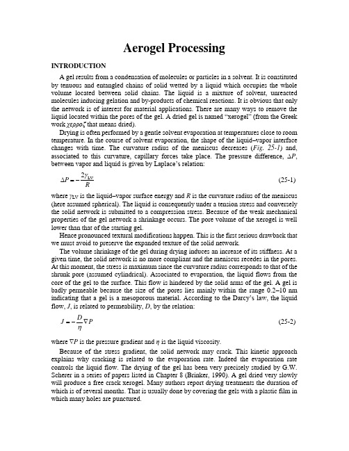
Aerogel ProcessingINTRODUCTIONA gel results from a condensation of molecules or particles in a solvent. It is constituted by tenuous and entangled chains of solid wetted by a liquid which occupies the whole volume located between solid chains. The liquid is a mixture of solvent, unreacted molecules inducing gelation and by-products of chemical reactions. It is obvious that only the network is of interest for material applications. There are many ways to remove the liquid located within the pores of the ge l. A dried gel is named ―xerogel‖ (from the Greek work χερροζ that means dried).Drying is often performed by a gentle solvent evaporation at temperatures close to room temperature. In the course of solvent evaporation, the shape of the liquid –vapor interface changes with time. The curvature radius of the meniscus decreases (Fig. 25-1) and, associated to this curvature, capillary forces take place. The pressure difference, ∆P , between vapor and liquid is given by Laplace’s relation:LV 2P R γ∆=- (25-1) where γLV is the liquid –vapor surface energy and R is the curvature radius of the meniscus (here assumed spherical). The liquid is consequently under a tension stress and conversely the solid network is submitted to a compression stress. Because of the weak mechanical properties of the gel network a shrinkage occurs. The pore volume of the xerogel is well lower than that of the starting gel.Hence pronounced textural modifications happen. This is the first serious drawback that we must avoid to preserve the expanded texture of the solid network.The volume shrinkage of the gel during drying induces an increase of its stiffness. At a given time, the solid network is no more compliant and the meniscus recedes in the pores. At this moment, the stress is maximum since the curvature radius corresponds to that of the shrunk pore (assumed cylindrical). Associated to evaporation, the liquid flows from the core of the gel to the surface. This flow is hindered by the solid arms of the gel. A gel is badly permeable because the size of the pores lies mainly within the range 0.2–10 nm indicating that a gel is a mesoporous material. According to the Darcy’s law, the liquid flow, J , is related to permeability, D , by the relation:DJ P η=-∇ (25-2) where ∇P is the pressure gradient and η is the liquid viscosity.Because of the stress gradient, the solid network may crack. This kinetic approach explains why cracking is related to the evaporation rate. Indeed the evaporation rate controls the liquid flow. The drying of the gel has been very precisely studied by G.W. Scherer in a series of papers listed in Chapter 8 (Brinker, 1990). A gel dried very slowly will produce a free crack xerogel. Many authors report drying treatments the duration of which is of several months. That is usually done by covering the gels with a plastic film in which many holes are punctured.Figure 25-1. Evolution of the curvature of liquid–vapor meniscus at the surface of a pore as a function of drying time, t.Cracking of the solid part of the gel is the second drawback usually encountered during drying. Freeze drying and supercritical drying are two processes which have been investigated to circumvent these difficulties.Freeze drying consists of lowering the temperature of liquid to induce a crystallization phenomenon. The solvent is then removed from its vapor state by decreasing the pressure (sublimation). This process applies well to solvents showing an appreciable vapor pressure at temperatures lower than crystallization temperature. Low molecular weight alcohols have very low crystallization temperatures (methanol: –94°C, ethanol: – 117°C). Water which transforms into ice crystal shows an important volume change associated to this transformation. The solid part of the gel is highly stressed and usually breaks into small pieces (Pajonk, 1989). Moreover the sublimation rate is quite slow. It is of about 140 kg/m2 h at 15°C. A solution which may, in imagination, avoid the large volume change produced by crystallization, is to transform liquid into glass. Unfortunately glass formation domain often occurs near eutectic point composition. As exemplified the glass temperature of mixture H2O-CH3OH is too low (–157°C) (Vuillard, 1961) to perform then sublimation at appreciable rate. Finally, one among the best liquids seems to be terbutanol whose the melting temperature is 25°C and which has a sublimation rate of 2800 kg/m2 h at 0°C. This solvent is not usual and a previous solvent exchange is often required. The textural properties of the gel such as the pore volume and the pore size distribution are approximately preserved. Nevertheless it seems difficult to obtain monolithic samples having significant thickness (higher than 10 mm) (Degn Egeberg, 1989). A detailedanalysis of the nucleation and crystallization phenomena occurring in the liquid wetting the solid part of the gel has been done by Scherer (Scherer, 1993). Crystallization starts from the liquid located at the external gel surface and the crystal–liquid interface moves from the surface to the core. Thus stresses appear as a consequence of the solid crust which forms at the surface and the volume change associated to the liquid–crystal transformation.Since the main consequences of drying are the shrinkage and the breakage, several experiments have been performed to overcome these drawbacks. We must underline that cracking has been chemically avoided by adding to the starting solution some compounds which give rise to gel having a narrow pore size distribution (formamide, glycerol, oxalic acid). Chemical additives controlling the drying step work well both with aqueous gels (Shoup, 1988) and those prepared from organometallic compounds (Hench, 1986).The increase of the stiffness of the solid part of the gel by a dissolution-redeposition effect allows to preserve the monolithicity of the gel while reducing the shrinkage (Mizuno, 1988). It is worth noticing that ageing the wet gel in a solution containing monomers gives analogous results (Einarsrud, 1998). An alternative way to produce crack free samples is to synthesize gels having very small pore sizes. During drying, nucleation and growth of bubbles occur within the liquid. This cavitation phenomenon induces the segmentation of the liquid which becomes under a lower tensile stress (Sarkar, 1994). On the other hand we must underline that sometimes cracking can be regarded as an advantage. As an example, an extensive cracking is beneficial in the synthesis of abrasive powders issued from sol–gel process.THE SUPERCRITICAL DRYING-PROCESSThe supercritical drying process has been proposed by Kistler. (Kistler, 1932) to dry, without textural modification, very tenuous solids wetted with a solvent.The main idea is to avoid capillary forces, which occur during drying, by a very peculiar pressure and temperature schedule applied to the liquid. Regarding only the liquid phase of the gel, it is obvious that one can modify its state by changing thermodynamic parameters such as the pressure and the temperature.Figure 25-2 shows a typical phase diagram for a pure compound. The parameters, P, T, v (usually the specific volume) are the variables which determine the state equation.Figures 25-3 and 25-4correspond to some projections of the previous three-dimensional diagram.Figure 25-2. Typical P, T,v diagram of a chemical compound.Figure 25-3. Pressure-specific volume diagram issued from diagram Figure 25-2.Figure 25-4. Pressure-temperature diagram showing the different domains solid, liquid and vapor and supercritical fluid (SF).The principle of supercritical drying is easily understood owing to Figure 25-4. The point, a, defines the couple pressure-temperature at which the three states of the compound are in equilibrium. Under atmospheric pressure, P at, the liquid transforms into vapor at boiling temperature (T B). The point, c, is the boundary of the vaporization curve corresponding to liquid–vapor separation. The point, c, is named the critical point. For a given compound the critical point is determined by associated critical pressure and temperature values. Above this point there is a continuum between the liquid and the vapor which can no more be distinguished. In this domain, there is an unique state named supercritical fluid (SF). This domain is not well defined. However a crude approximate consists in locating the supercritical fluid domain by a P, T area as indicated in Figure 25-4.At room temperature (T R) starting with a liquid (N) and increasing both the temperature and the pressure, the compound follows the path N → Q (Fig. 25-5). At Q, the compound is supercritical under its fluid state. It can be observed that starting with the vapor state at low pressure (M) and increasing again the temperature and the pressure, the compound reaches the point Q where it is in the same state than that previously mentioned. Thus we have obtained the same homogeneous and unique state using different paths. For a given compound, its properties depend obviously on the pressure and temperature values and can be easily varied accordingly.Figure 25-5. Different paths to reach the supercritical fluid domain.It is evidenced that starting from the liquid state (point N) and increasing the temperature and pressure up to the supercritical fluid state (point Q), an adequate decrease in the temperature and pressure (see full arrow) will lead to the vapor state (point M). The net effect of these successive steps results in the transformation of liquid into vapor. A drying step has been carried out. The change from the liquid to the vapor follows a path that avoids the vaporization curve (ac). During heating, the surface energy associated to the interface liquid–gas progressively decreases and vanishes when the superfluid state is attained. Consequently capillary forces (see equation (1)) are no more acting and the solid part of the gel does not suffer stresses. Drying does not induce stresses and the texture of the solid network does not collapse. The aerogel theoretically does not exhibit shrinkage, its porous volume is identical to that of the starting gel. In addition, this drying process must lead to crack free material when performed under controlled conditions. Table 25-1 summarizes the different solvents used to perform supercritical drying (SCD). The critical pressure and temperature values can be easily obtained by using classical autoclave made of stainless steel.TABLE 25-1. CRITICAL PARAMETERS OF COMPOUNDS USED TO PERFORM SCDSupercritical drying solvents belong to two families: organic and inorganic solvents. The organic solvents are mainly alcohols, ether and acetone. For safety conditions, ether and acetone will be rarely used. Among the alcohols, those having short length are preferred because they do not decompose at high temperature and pressure. Moreover, because of their quite high critical temperature, organic solvents usually react with the solid network. An esterification reaction often occurs. In the case of silica gel prepared from hydrolysis of organometallic compounds diluted in alcohol, the nature of the surface of solid particle is modified according to the reaction:\\2//Si OH+R OH Si OR +H O ---→-- The silanol (Si –OH) surface groups are replaced by chemical groups \/Si OR -- which exhibit a hydrophobic effect. A silica aerogel obtained by alcohol SCD floats when placed onto water. With time, air moisture will react again with \/Si OR -- Consequently the aerogel becomes hydrophilic according to the reverse reaction\\2//Si OR +H O Si OH+ROH --→-- Water absorbs again on the pore walls of the aerogel inducing again capillary forces. The monolithicity of the aerogel can be lost. The second drawback of organic solvent used in supercritical SCD process is associated to the nature of the solid network. Because the required high critical temperature, only gels built up by strong chemical bonds are able to resist the heat treatment. Physical gels are gels formed with quite weak chemical bonds such as hydrogen or Van der Waals. After setting, this sort of gel is easily transformed into a liquid state by a vigorous stirring. These gels are damaged when submitted to a heat treatment. That means that only chemical gels whose the solid network consists of strong (covalent or ionic) bonds are able to be transformed into crack free aerogels. Inorganic gels which obey to these conditions are not very numerous (silica and binary silicates doped with Al 2O, TiO 2, ZrO 2, B 2O 3). Most of organic gels are not strong enough to be dried using alcohol supercritical drying. However a recent paper reports an organic gel dried using alcohol (Albert, 2001).Inorganic solvents which allow supercritical drying are fluorinated compounds (freon), SO 2 and carbon dioxide (Woignier, 1984). Fluorinated compounds are not authorized because they cause serious damaging of ozone atmospheric layer. On the other hand, water is always avoided because under supercritical conditions it behaves as a strong mineralizer toward inorganic material and more particularly with respect to amorphous silica. Contrarily to quartz for which a retrograde solubility allows the synthesis of monocrystals in the supercritical region, the solubility of silica gel continues to increase and reaches values in the range of 0.23% in weight (Kennedy, 1950). The most attractive solvent is the carbon dioxide. It is chemically unreactive and its critical temperature is close to room temperature. It permits to dry gels which do not suffer temperatures higher than 100°C under suitable safety conditions. However the starting gels are synthesized at room temperature using alcohol, water or acetone as solvents. Consequently the first step of the drying procedure must include a solvent exchange with CO 2 liquid or CO 2 supercriticalfluid. This exchange involves solvents miscible with CO2 (Francis, 1954; Baker, 1957). However when the network of organic gel resists high temperature such as phenolic furfural gel a drying procedure using methanol may be used (Albert, 2001). It is worth noticing the recent success in forming directly aerogels in supercritical carbon dioxide (Loy, 1997). This synthesis way seems attractive since avoiding initial hazardous organic solvent extraction.A disadvantage of CO2supercritical drying is related to the hydrophilic property of resulting aerogels. They absorb water with time and capillary condensation can occur inducing again capillary forces that in turn can lead to textural damage. Consequently CO2 supercritically dried aerogel must be preserved into a closed evacuated dessicator.EXPERIMENTAL PROCEDUREExperimental Set-UpFigure 25-6 shows a schematic autoclave set up. Sometimes the autoclave is equipped with sapphire windows permitting observation and optical measurements. A CO2SCD equipment needs a pressure compressor and a chiller to transform CO2 vapor into CO2 liquid (or SF).Alcohol SCD is performed directly with gel imbedded with alcohol. The usual thermal schedule(Fig. 25-7) consists in a heating step up to a temperature (T W) higher than the critical one. Accordingly, the pressure (P W) reaches a value higher than the critical pressure (P c). At this moment (point Q) an isothermal treatment is performed while the output valve is gently opened to vent the autoclave. When the pressure in the autoclave approaches the atmospheric pressure (point M), the autoclave is fluxed with a neutral gas (nitrogen or argon). The autoclave is then cooled down to room temperature,T R. The autoclave fluxing may be carried out during cooling at any temperature higher enough to avoid liquid condensation within the smallest pores of the gel. Since the solvent vapor is changed by an inert gas, no liquid condensation arises.Figure 25-6. A schematic apparatus with equipment allowing to perform supercritical drying.Figure 25-7. Usual P, T path allowing to obtain aerogel.Figure 25-8. Ways to compare the geometrical dimensions of samples as a function of the different steps leading to aerogels.Figure 25-8schematically displays the different steps corresponding to a classical supercritical schedule (path (a)). Thus the geometrical dimensions of the gel and aerogel can be directly estimated by comparing the state 1 and 2. The volume lost is easily calculated from the bulk density of aerogel. The skeletal density measured by helium pycnometry is 2 g/cm3for silica aerogel. On the other hand, the path b is sometimes employed to have information about the textural changes induced by chemical reactions occurring during the temperature (and obviously, the pressure) increase. This path consists in cooling down the autoclave after the initial heating step. In that case an isothermal treatment is not performed. The SCF separates again into vapor and liquid as the temperature decreases. Using the thermoporometry technique which works on wetted samples, the difference in textural properties between the starting gel (state 1) and the gel which has been only submitted to the initial heating step (state 3) is evaluated (Pauthe, 1991).We must underline that several authors (Woignier, 1924; Mulder, 1986) suggest to pressurize the autoclave cell with a neutral gas and then to increase the temperature. The pressure increases with temperature or can be maintained constant by a gentle opening of a venting valve while the temperature rises (Fig. 25-9). The escaping gas is always condensed (during heating and/or depressurization step) to be further analyzed.Figure 25-9. Pressurization of autoclave at the onset of supercritical drying.With respect to low temperatures involved in the CO2 SCD, it is possible to increase the pressure using a piston located inside the autoclave vessel or by introducing directly CO2 pressured with an external compressor.Critical VolumeIn the case of alcohols (and obviously acetone or ether) the autoclave is usually filled with an additional amount of SCD solvent. This additional solvent is often poured on the top of the gel and between the walls of the autoclave and the container in which the gel has been formed(Fig. 25-10). The role played by the additional solvent may be understood thanks to Figure 25-11. The specific volume, v, is the ratio volume of autoclave/mass of alcohol. The manner to fill the autoclave with alcohol modifies this parameter since the volume of the autoclave is constant. When the autoclave contains a high amount of liquid, the specific volume is low and conversely an autoclave mainly filled with vapor corresponds to a high v value.Assuming that the autoclave is previously evacuated, A and B points correspond to room temperature differently filled autoclave. Obviously, the autoclave contains an amount of liquid and vapor which may be estimated from points E and D.Starting with a mixture represented by A and increasing the temperature of autoclave, the respective quantities of liquid and vapor vary (line A → a). When the temperature reaches T a, the solvent is under a liquid state. This means that the interface of the liquid–vapor interface moves toward the top of the autoclave during heating.Figure 25-10. Autoclave vessel containing an additional amount of solvent.Figure 25-11. Liquid –vapor separation curve in the T, v diagram. Note that solid –liquid and solid –vapor domains are not shown for clarity.Under classical experimental conditions the vapor consists of solvent vapor and atmospheric gases (N 2, O 2). These latter play a minor role regarding the high pressures involved by the solvent heating.Conversely a mixture of liquid and vapor corresponding to v B (point B) will transform into gas at a temperature above T B . Consequently, since the solvent is entirely converted into vapor that means that the interface recedes and disappears when the last drop of liquid located at the autoclave bottom evaporates. Figure 25-12 summaries the different evolutions of the liquid –vapor interface when the temperature is ramped. Obviously there is a peculiar specific volume, v*, for which the level of the interface liquid –solid remains about constant with temperature rise.Thus addition of an amount of liquid solvent is advised to avoid the moving of interface downwards. If additional solvent is too low (such as V A ), at a moment during heating, the solid part of the gel is not wetted with liquid and capillaries forces are created. The upper part of the gel shows an extended shrinkage due to capillary stresses while the bottom exhibits a small shrinkage. Such differential shrinkage between the upper and the lower part of aerogel indicates that the SCD has been performed with an inadequate solvent amount. For silica gels prepared with alkoxysilane and alcohol as solvents, the critical specific volume has about the same value:33Methanol: 3.67 cm /gEthanol: 3.62 cm /gIt has been experimentally evidenced that the shrinkage and the monolithicity of aerogel depend on the amount of additional solvent (Phalippou, 1990).It must be underlined that the effect of the initial prepressure corresponds to a shift on the v scale in Figure 25-11. A nitrogen (or argon) prepressure is roughly equivalent to adecrease in the available volume of autoclave. Consequently for a given amount of solvent the specific volume is lowered and the temperature increase causes the liquid level to climb. Thus the prepressure, when perfectly controlled, permits to decrease the quantity of solvent required to perform SCD under conditions preserving the texture of the solid.Figure 25-12. Evolution of liquid–vapor interface during a heating treatment as a function of specific volume values. The arrows indicate the interface displacement.A few variants can be found in the literature. It has been observed that for silica gels obtained from alkoxide compounds, the gelation can be done during the temperature rise (Prassas, 1984). On the other hand it is possible to faster the aerogel production owing to a fast pressure increase associated to liquid expansion in a mould. A fritted mould permits the internal fluid to escape slightly to maintain the pressure constant (Gross, 1998). In this process the rate of leakage is equal to that of alcohol expansion.For CO2SCD the critical volume is not a parameter of interest since the gel is synthesized in an organic solvent (alcohol, acetone, ether) or in water which must be replaced with CO2 liquid or SF prior to supercritical drying.Solvent ExchangeIn the CO2 SCD the solvent exchange is the step which is the most time consuming. The solvent exchange must be complete to obtain monolithic aerogels.When the initial solvent is water a first solvent exchange is required because liquid CO2 and water are not miscible. Amyl acetate is entirely soluble with water and CO2. It is the main solvent used for CO2drying of living organisms before observations using transmission electron microscopy.Alcohol and acetone which are miscible with CO2 liquid are the favorite solvents when the starting gel has been synthesized in water.When the washed gel yet contains small quantities of water, the phase diagrams (CO2–H2O–ethanol) (Baker, 1957) and (CO2–H2O–acetone) (Panagiotopoulos, 1985) permits to select parameters (P, T) corresponding to one phase region. A complete removing of water traces is required if one wants to avoid some difficulties occurring during SF depressurization. These difficulties originate from the selective extraction of organic compounds with CO2 while water is not eliminated. For silica gel, a water free gelation has been produced from TMOS and formic acid within SF CO2. Since this organic solvent is miscible with SF CO2 (Loy, 1997) the solvent exchange which is the limiting step of CO2 is avoided and the supercritical drying directly performed.The quality of the liquid replacement is crucial for obtaining monolithic aerogel sample. This crucial stage has been investigated by several authors. Starting with gels containing an amount of alcohol required to avoid a too fast solvent evaporation, it was evidenced that the alcohol removing depends on its location. Free alcohol located outside the gel is rapidly extracted by CO2, while alcohol within the gel is difficult to remove. For cylindrical gel with a diameter, d, of 15 mm, 3 h are needed to replace alcohol with CO2-SCD. This duration does not depend on the temperature. It depends mainly on the details of the gel texture. It is expected to vary as (Van Bommel, 1994):2(25-3) t dwhere d is the diameter of cylindrical samples.The diffusion of liquid CO2into a gel filled with ethanol has been followed by the interface motion between the transparent and the damaged zone observed in the resulting aerogel. An aerogel completely exchanged is monolithic and transparent while the part of the gel which contains residual alcohol is damaged (Rogacki, 1995). The evolution with time of the alcohol concentration in liquid CO2removed has been recently precisely measured using online chromatograph (Wawrzyniak, 2001).It is noteworthy that the solvent exchange with CO2 induces a dimensional change of gel sample. For example the gel sample shrinks as acetone is replaced with CO2. The shrinkage is due to compressive stresses which act on the solid part as a result of osmotic pressure. This osmotic phenomenon arises from the increase of interface energy when solid acetone transforms into solid–liquid CO2 (Yeng Wang, 1998).GEOMETRICAL DIMENSIONS AND KINETIC PARAMETERS When aerogels are obtained free of cracks, we can say that during SCD process the gel has suffered minor stresses. Experiments indicate that both thermodynamic parameters (P, T) dimension and nature of the gel play a very important role on monolithicity.Numerous investigations deal with silica gels. Silica gels belong to two families depending upon the pH preparation conditions.Silica gels obtained from acid hydrolysis of alkoxides have a mean pore size in the range of 3–4 nm. For base catalyzed gels, the mean pore size is shifted toward higher values. The behavior of silica gels varies with respect to these different textural properties.Associated to the pore size and the pore size distribution the gels have different permeability values. Base catalyzed gels have a liquid permeability in the range of 10–20 nm2, acid catalyzed gels in the range of a few nm2. In both cases the silica network is covered with silanols Si–OH groups which react together with time to form water and siloxane Si–O–Si bridges. Such a reaction leads to the shrinkage of the solid part of the gel while the liquid within the pores is expelled out of the sample. This phenomenon is called syneresis. It is thermally activated and its intensity depends on the details of the solid network texture. When silanol groups borne by the arms of solids are very close such a phenomenon is very efficient and causes a significant shrinkage.In comparison, base catalyzed gels which consist of an arrangement of large particles and which exhibit a higher mean pore size are less sensitive than acid ones. Basic gels show a weak syneresis phenomenon and the associated shrinkage is quite of low extent.The first stage of SCD consists in autoclave heating. Both the solid part of the gel and solvent are heated. Several features are related to this thermal treatment. As above mentioned, syneresis phenomenon takes place and the solid shrinks. On the other hand, the liquid expands. The solvent located outside the silica network moves as mentioned previously (see Section EXPERIMENTAL PROCEDURE). The solvent located within the pores tends to expand and consequently the liquid must escape from the solid network. However the silica framework is not expected to expand as a function of temperature according to the very low thermal expansion of amorphous silica.The net effect of these two phenomena is to place the liquid located within the pores under a compressive stress and consequently the solid phase under an associated tensile stress. A detailed calculation of the stresses created during this first stage of SCD has been reported. Stresses depend on the geometrical dimensions and the permeability of gels (Scherer, 1992). The results clearly indicate that for acid or neutral gels, syneresis is the main phenomenon giving rise to high stresses which can lead to gel failure. The observed framework of cracks(Fig. 25-13a) is in good agreement with offered explanations and calculation. Base catalyzed gels can be considered as macroporous. They exhibit a higher permeability and syneresis is reduced. The gel shrinkage is quite weak and often the gel sticks to the walls of the container. Under such conditions the liquid mainly escapes through the free upper surface of the gel. The gel network is consequently submitted to a pure uniaxial tensile stress. If the stress developed during heating becomes higher than the rupture stress the gel breaks into several slides as indicated in Figure 25-13b.Sample dimensions and kinetic parameters play also a significant role during the depressurization step. Depressurization is carried out at about 300°C for alcohol and at about 50°C for CO2. It is performed during an isothermal treatment. The pressure in the autoclave is lowered at a rate controlled by the opening of a microvalve. As soon as the pressure decreases in the autoclave the superfluid invading the pores of the gel tends to escape from the surface. Thus a fluid flow occurs from the core to the surface. If the network shows a low permeability a pressure gradient is created and stresses occur.。
THE JOURNAL OF SUPERCRITICAL FLUIDS投稿须知

THE JOURNAL OF SUPERCRITICAL FLUIDSAUTHOR INFORMATION PACK TABLE OF CONTENTS• Description• Audience• Impact Factor• Abstracting and Indexing • Editorial Board• Guide for Authors p.1p.1p.1p.1p.2p.3ISSN: 0896-8446DESCRIPTIONThe Journal of Supercritical Fluids is an international journal devoted to the fundamental and applied aspects of supercritical fluids and processes. Its aim is to provide a focused platform for academic and industrial researchers to report their findings and to have ready access to the advances in this rapidly growing field. Its coverage is multidisciplinary and includes both basic and applied topics. Thermodynamics and phase equilibria, reaction kinetics and rate processes, thermal and transport properties, and all topics related to processing such as separations (extraction, fractionation, purification, chromatography) nucleation and impregnation are within the scope. Accounts of specific engineering applications such as those encountered in food, fuel, natural products, minerals, pharmaceuticals and polymer industries are included. Topics related to high pressure equipment design, analytical techniques, sensors, and process control methodologies are also within the scope of the journal. The journal publishes original contributions in all theoretical and experimental aspects of the science and technology of supercritical fluids and processes. Papers that describe novel instrumentation, new experimental methodologies and techniques, predictive procedures and timely review articles are also acceptable.AUDIENCEChemical engineers, Physical chemistsIMPACT FACTOR2009: 2.639 © Thomson Reuters Journal Citation Reports 2010ABSTRACTING AND INDEXINGScopusEDITORIAL BOARDEditor-in-Chief:Erdogan Kiran, Dept. of Chemical Engineering, Virginia Polytechnic Institute and State University, 141 Randolph Hall, Blacksburg, VA 24061, USA, Fax: +1 540 231 5022, Email: ekiran@Regional Editor (Europe):Gerd Brunner, Arbeitsbereich Termische Verfahrenstechnik, Technische Universität Hamburg-Harburg (TUHH), Eißendorfer Str. 38, 21073 Hamburg, Germany, Fax: +49 40 42878 4072, Email: brunner@tu-harburg.de Regional Editor (Asia):Richard Smith, Jr., Research Ctr. for Supercritical Fluid Technology, Tohoku University, Aramaki Aza Aoba 6-6-11-413, Aoba-ku, 980-8579 Sendai, Japan, Fax: +81 22 795- 5863, Email: smith@scf.che.tohoku.ac.jp Editorial Board:M. Arai, Sapporo, JapanS. Bottini, Bahía Blanca, ArgentinaE.A. Brignole, Bahía Blanca, ArgentinaA. Çalimli, Ankara, TurkeyF. Cansell, Pessac cedex, FranceO. Catchpole, Lower Hutt, New ZealandM.J. Cocero, Valladolid, SpainC. Erkey, Istanbul, TurkeyJ.L. Fulton, Richland, WA, USAM. Goto, Kumamoto, JapanB. Han, Beijing, ChinaS.M. Howdle, Nottingham, UKK.P. Johnston, Austin, TX, USAI. Kikic, Trieste, ItalyJ.W. King, Fayetteville, AR, USAŽ. Knez, Maribor, SloveniaS. Koda, Tokyo, JapanA. Kruse, Karlsruhe, GermanyM. Mazzotti, Zurich, SwitzerlandM.A. McHugh, Richmond, VA, USAM. Nunes da Ponte, Caparica, PortugalM. Perrut, Champigneulles, FranceC.J. Peters, Abu Dhabi, United Arab EmiratesE. Reverchon, Fisciano (SA), ItalyP.E. Savage, Ann Arbor, MI, USAL.T. Taylor, Blacksburg, VA, USAF. Temelli, Edmonton, AB, CanadaJ.W. Tester, Ithaca, NY, USAM.C. Thies, Clemson, SC, USAD.L. Tomasko, Columbus, OH, USAM. Türk, Karlsruhe, GermanyE. Weidner, Bochum, GermanyGUIDE FOR AUTHORSINTRODUCTIONThe Journal of Supercritical Fluids is an international journal devoted to the fundamental and applied aspects of supercritical fluids and processes. Its aim is to provide a focused platform for academic and industrial researchers to report their findings and to have ready access to the advances in this rapidly growing field. Its coverage is multidisciplinary and includes both basic and applied topics. Thermodynamics and phase equilibria, reaction kinetics and rate processes, thermal and transport properties, and all topics related to processing such as separations (extraction, fractionation, purification, chromatography) nucleation and impregnation are within the scope. Accounts of specific engineering applications such as those encountered in food, fuel, natural products, minerals, pharmaceuticals and polymer industries are included. Topics related to high pressure equipment design, analytical techniques, sensors, and process control methodologies are also within the scope of the journal. The journal publishes original contributions in all theoretical and experimental aspects of the science and technology of supercritical fluids and processes. Papers that describe novel instrumentation, new experimental methodologies and techniques, predictive procedures and timely review articles are also acceptable.Types of Paper• Research papers• Reviews of specialized topics within the scope of the journalContributions are accepted on the understanding that the authors have obtained the necessary authority for publication. Submission of an article must be accompanied by a statement that the article is original and unpublished and is not being considered for publication elsewhere.Authors considering a review article are requested to consult one of the Editors before submission and provide an outline and a justification for the necessity of the review.Manuscripts should not exceed 6,000 words for research papers and 15,000 words for review articles. Only review articles should contain a table of contents.Contact details for submissionAuthors are requested to submit their original manuscript to: Professor E. Kiran (Editor-in-Chief), Professor G. Brunner (European submissions), or Professor R.L. Smith, Jr. (Asian submissions). BEFORE YOU BEGINEthics in PublishingFor information on Ethics in Publishing and Ethical guidelines for journal publication see /publishingethics and /ethicalguidelines.Conflict of interestAll authors are requested to disclose any actual or potential conflict of interest including any financial, personal or other relationships with other people or organizations within three years of beginning the submitted work that could inappropriately influence, or be perceived to influence, their work. See also /conflictsofinterest.Submission declaration and verificationSubmission of an article implies that the work described has not been published previously (except in the form of an abstract or as part of a published lecture or academic thesis), that it is not under consideration for publication elsewhere, that its publication is approved by all authors and tacitly or explicitly by the responsible authorities where the work was carried out, and that, if accepted, it will not be published elsewhere in the same form, in English or in any other language, including electronically without the written consent of the copyright-holder. To verify originality, your article may be checked by the originality detection software iThenticate. See also /editors/plagdetect.Changes to authorshipThis policy concerns the addition, deletion, or rearrangement of author names in the authorship of accepted manuscripts:Before the accepted manuscript is published in an online issue: Requests to add or remove an author, or to rearrange the author names, must be sent to the Journal Manager from the corresponding author of the accepted manuscript and must include: (a) the reason the name should be added or removed, or the author names rearranged and (b) written confirmation (e-mail, fax, letter) from all authors that they agree with the addition, removal or rearrangement. In the case of addition or removal of authors, this includes confirmation from the author being added or removed. Requests that are not sent by the corresponding author will be forwarded by the Journal Manager to the corresponding author, who must follow the procedure as described above. Note that: (1) Journal Managers will inform the Journal Editors of any such requests and (2) publication of the accepted manuscript in an online issue is suspended until authorship has been agreed.After the accepted manuscript is published in an online issue: Any requests to add, delete, or rearrange author names in an article published in an online issue will follow the same policies as noted above and result in a corrigendum.CopyrightUpon acceptance of an article, authors will be asked to complete a 'Journal Publishing Agreement' (for more information on this and copyright see /copyright). Acceptance of the agreement will ensure the widest possible dissemination of information. An e-mail will be sent to the corresponding author confirming receipt of the manuscript together with a 'Journal Publishing Agreement' form or a link to the online version of this agreement.Subscribers may reproduce tables of contents or prepare lists of articles including abstracts for internal circulation within their institutions. Permission of the Publisher is required for resale or distribution outside the institution and for all other derivative works, including compilations and translations (please consult /permissions). If excerpts from other copyrighted works are included, the author(s) must obtain written permission from the copyright owners and credit the source(s) in the article. Elsevier has preprinted forms for use by authors in these cases: please consult /permissions.Retained author rightsAs an author you (or your employer or institution) retain certain rights; for details you are referred to: /authorsrights.Role of the funding sourceYou are requested to identify who provided financial support for the conduct of the research and/or preparation of the article and to briefly describe the role of the sponsor(s), if any, in study design; in the collection, analysis and interpretation of data; in the writing of the report; and in the decision to submit the paper for publication. If the funding source(s) had no such involvement then this should be stated. Please see /funding.Funding body agreements and policiesElsevier has established agreements and developed policies to allow authors whose articles appear in journals published by Elsevier, to comply with potential manuscript archiving requirements as specified as conditions of their grant awards. To learn more about existing agreements and policies please visit /fundingbodies.Language and language servicesPlease write your text in good English (American or British usage is accepted, but not a mixture of these). Authors who require information about language editing and copyediting services pre- and post-submission please visit /languageediting or our customer support site at for more information.SubmissionSubmission to this journal proceeds totally online. Use the following guidelines to prepare your article. Via the homepage of this journal (/supflu/) you will be guided stepwise through the creation and uploading of the various files. The system automatically converts source files to a single Adobe Acrobat PDF version of the article, which is used in the peer-review process. Please note that even though manuscript source files are converted to PDF at submission for the review process, these source files are needed for further processing after acceptance. All correspondence, including notification of the Editor's decision and requests for revision, takes place by e-mail and via the author's homepage, removing the need for a hard-copy paper trail.RefereesPlease submit, with the manuscript, the names and e-mail addresses of 5 potential referees who are knowledgeable of the research subject. Note that the editor retains the sole right to decide whether or not the suggested reviewers are used.PREPARATIONAuthors in Japan please note that information about how to have the English of your paper checked, corrected and improved (before submission) is available from:Elsevier JapanHigashi Azabu 1-chome Building 4F1-9-5 Higashi Azabu, Minato-kuTokyo 106JapanTel: +81 (03) 5561 5032Fax: +81 (03) 5561 5045Article StructureAll manuscripts are required to be submitted in double-spaced line format. This pertains to all text, tables, figure captions and references.Subdivision - numbered sectionsDivide your article into clearly defined and numbered sections. Subsections should be numbered 1.1 (then 1.1.1, 1.1.2, ...), 1.2, etc. (the abstract is not included in section numbering). Use this numbering also for internal cross-referencing: do not just refer to "the text". Any subsection may be given a brief heading. Each heading should appear on its own separate line.IntroductionState the objectives of the work and provide an adequate background, avoiding a detailed literature survey or a summary of the results.Material and methodsProvide sufficient detail to allow the work to be reproduced. Methods already published should be indicated by a reference: only relevant modifications should be described.ResultsResults should be clear and concise.DiscussionThis should explore the significance of the results of the work, not repeat them. A combined Results and Discussion section is often appropriate. Avoid extensive citations and discussion of published literature.ConclusionsThe main conclusions of the study may be presented in a short Conclusions section, which may stand alone or form a subsection of a Discussion or Results and Discussion section.AppendicesIf there is more than one appendix, they should be identified as A, B, etc. Formulae and equations in appendices should be given separate numbering: Eq. (A.1), Eq. (A.2), etc.; in a subsequent appendix, Eq. (B.1) and so on. Similarly for tables and figures: Table A.1; Fig. A.1, etc.Essential title page information• Title.Concise and informative. Titles are often used in information-retrieval systems. Avoid abbreviations and formulae where possible.• Author names and affiliations.Where the family name may be ambiguous (e.g., a double name), please indicate this clearly. Present the authors' affiliation addresses (where the actual work was done) below the names. Indicate all affiliations with a lower-case superscript letter immediately after the author's name and in front of the appropriate address. Provide the full postal address of each affiliation, including the country name, and, if available, the e-mail address of each author.• Corresponding author. Clearly indicate who will handle correspondence at all stages of refereeing and publication, also post-publication. Ensure that telephone and fax numbers (with country and area code) are provided in addition to the e-mail address and the complete postal address. Contact details must be kept up to date by the corresponding author.• Present/permanent address. If an author has moved since the work described in the article was done, or was visiting at the time, a "Present address" (or "Permanent address") may be indicated as a footnote to that author's name. The address at which the author actually did the work must be retained as the main, affiliation address. Superscript Arabic numerals are used for such footnotes. AbstractEach manuscript must include an abstract of about 100-150 words, reporting concisely on the purpose and results of the paper. An abstract is often presented separate from the article, so it must be able to stand alone. For this reason, References should be avoided, but if essential, they must be cited in full, without reference to the reference list. Also, non-standard or uncommon abbreviations should be avoided, but if essential they must be defined at their first mention in the abstract itself. Graphical AbstractIt is required that the author submits the necessary components of a graphical abstract (see example). These components consist of a pictogram, the article title, and the names of the authors and their respective affiliations as they appear in the article. Maximum final dimensions of the pictogram are 5 X 5 cm with a required minimum pixilation of 300 ppi. Bear in mind readability after reduction, especially if using one of the figures from the article itself. Graphical abstracts will be collated to provide a contents list for rapid scanning.HighlightsHighlights are mandatory for this journal. They consist of a short collection of bullet points that convey the core findings of the article and should be submitted in a separate file in the online submission system. Please use 'Highlights' in the file name and include 3 to 5 bullet points (maximum 85 characters per bullet point including spaces). See /highlights for examples. KeywordsImmediately after the abstract, provide a maximum of 6 keywords, using American spelling and avoiding general and plural terms and multiple concepts (avoid, for example, "and", "of"). Be sparing with abbreviations: only abbreviations firmly established in the field may be eligible. These keywords will be used for indexing purposes. Keywords should be selected, if appropriate, from the following classes: theoretical methods, experimental methods, phenomena, materials, and applications. AbbreviationsDefine abbreviations that are not standard in this field in a footnote to be placed on the first page of the article. Such abbreviations that are unavoidable in the abstract must be defined at their first mention there, as well as in the footnote. Ensure consistency of abbreviations throughout the article. AcknowledgementsCollate acknowledgements in a separate section at the end of the article before the references and do not, therefore, include them on the title page, as a footnote to the title or otherwise. List here those individuals who provided help during the research (e.g., providing language help, writing assistance or proof reading the article, etc.).Nomenclature and unitsUnits: The SI system should be used for all scientific and laboratory data; if, in certain instances, it is necessary to quote other units, these should be added in parentheses. Temperatures may be given in Kelvin or degrees Celsius. The unit 'billion' (109 in America, 1012 in Europe) is ambiguous and must not be used.Symbols and Abbreviations: Only widely accepted symbols and forms of abbreviation should be used, but always give the full expression followed by the abbreviation the first time it appears in the text. Abbreviations and symbols used in tables and figures should be explained in the legends. The number of symbols should not exceed 10 per manuscript.FootnotesFootnotes should be used sparingly. Number them consecutively throughout the article, using superscript Arabic numbers. Many wordprocessors build footnotes into the text, and this feature may be used. Should this not be the case, indicate the position of footnotes in the text and present the footnotes themselves separately at the end of the article. Do not include footnotes in the Reference list.Table footnotesIndicate each footnote in a table with a superscript lowercase letter.ArtworkElectronic artworkGeneral points• Make sure you use uniform lettering and sizing of your original artwork.• Save text in illustrations as "graphics" or enclose the font.• Only use the following fonts in your illustrations: Arial, Courier, Times, Symbol.• Number the illustrations according to their sequence in the text.• Use a logical naming convention for your artwork files.• Provide captions to illustrations separately.• Produce images near to the desired size of the printed version.• Submit each figure as a separate file.A detailed guide on electronic artwork is available on our website:/artworkinstructionsYou are urged to visit this site; some excerpts from the detailed information are given here. FormatsRegardless of the application used, when your electronic artwork is finalised, please "save as" or convert the images to one of the following formats (note the resolution requirements for line drawings, halftones, and line/halftone combinations given below):EPS: Vector drawings. Embed the font or save the text as "graphics".TIFF: color or grayscale photographs (halftones): always use a minimum of 300 dpi.TIFF: Bitmapped line drawings: use a minimum of 1000 dpi.TIFF: Combinations bitmapped line/half-tone (color or grayscale): a minimum of 500 dpi is required. DOC, XLS or PPT: If your electronic artwork is created in any of these Microsoft Office applications please supply "as is".Please do not:• Supply files that are optimised for screen use (like GIF, BMP, PICT, WPG); the resolution is too low;• Supply files that are too low in resolution;• Submit graphics that are disproportionately large for the content.Color artworkPlease make sure that artwork files are in an acceptable format (TIFF, EPS or MS Office files) and with the correct resolution. If, together with your accepted article, you submit usable color figures then Elsevier will ensure, at no additional charge, that these figures will appear in color on the Web (e.g., ScienceDirect and other sites) regardless of whether or not these illustrations are reproduced in color in the printed version. For color reproduction in print, you will receive information regarding the costs from Elsevier after receipt of your accepted article. Please indicate your preference for color in print or on the Web only. For further information on the preparation of electronic artwork, please see /artworkinstructions.Please note: Because of technical complications which can arise by converting color figures to "gray scale" (for the printed version should you not opt for color in print) please submit in addition usable black and white versions of all the color illustrations.Figure captionsEnsure that each illustration has a caption. Supply captions separately, not attached to the figure. A caption should comprise a brief title (not on the figure itself) and a description of the illustration. Keep text in the illustrations themselves to a minimum but explain all symbols and abbreviations used. TablesNumber tables consecutively in accordance with their appearance in the text. Place footnotes to tables below the table body and indicate them with superscript lowercase letters. Avoid vertical rules. Be sparing in the use of tables and ensure that the data presented in tables do not duplicate results described elsewhere in the article.ReferencesReferences should be relevant and up-to-date. All publications cited in the text should be presented in a list of references and vice versa following the text of the manuscript. In the text refer to references by a number in square brackets on the line (e.g. Since Lever [1] ), and the full reference including the title should be given in a numerical list at the end of the paper. Any references cited in the abstract must be given in full. Unpublished results and personal communications are not recommended in the reference list, but may be mentioned in the text. If these references are included in the reference list they should follow the standard reference style of the journal and should includea substitution of the publication date with either "Unpublished results" or "Personal communication". Citation of a reference as "in press" implies that the item has been accepted for publication. All manuscripts must consistently adhere to the Reference Style as described below.Reference management softwareThis journal has standard templates available in key reference management packages EndNote (/support/enstyles.asp) and Reference Manager (/support/rmstyles.asp). Using plug-ins to wordprocessing packages, authors only need to select the appropriate journal template when preparing their article and the list of references and citations to these will be formatted according to the journal style which is described below. Reference styleText: Indicate references by number(s) in square brackets in line with the text. The actual authors can be referred to, but the reference number(s) must always be given.Example:"..... as demonstrated [3,6]. Barnaby and Jones [8] obtained a different result ...."List:Number the references (numbers in square brackets) in the list in the order in which they appear in the text. Each reference appearing in the list must have been referred to in the text. Reference to a journal publication: Full journal names should be used in reference to a journal publication. However, for "Journal" or "Journal of", the abbreviation of "J." is acceptable as in "J. Supercritical Fluids" or "Chemical Engineering J."Authors' initials and last names should be followed by the full title of the article, full journal name, volume, year in parentheses, and the pages.Examples:[1] J. van der Geer, J.A.J. Hanraads, R.A. Lupton, The art of writing a scientific article, J. Scientific Communication 163 (2000) 51-59.[2] M. Bulut, C. Erk, Improved synthesis of some hydroxycoumarins, Dyes and Pigments 30 (1996) 99-104.Reference to a book:Examples:[3] W. Strunk Jr., E.B. White, The Elements of Style, 3rd ed., Macmillan, New York, 1979, pp.5-28.[4] A.B.P. Lever, Inorganic Electronic Spectroscopy, Elsevier, Amsterdam, 1968, pp. 29-48. Reference to a chapter in an edited book:Examples:[5] G.R. Mettam, L.B. Adams, How to prepare an electronic version of your article, in: B.S. Jones, R.Z. Smith (Eds.), Introduction to the Electronic Age, E-Publishing Inc., New York, 1999, pp. 281-304. [6] L.V. Morris, Referring to a chapter in a book, in: S. Ottogalli, D.T. Parker (Eds.), Sample Reference Formats, Academic Publishing Co., New York, 2009, pp. 115-206.Reference to publications in proceedings:Examples:[7] M. Cocero, J. Soria, O. Ganado, R. Gonzales, F. Fernandez-Polanco, Behavior of a cooled wall reactor for supercritical water oxidation, in: P. Rudolf von Rohr, C. Trepp (Eds.), Proceedings of High Pressure Chemical Engineering, Elsevier B.V., Amsterdam, 1996, p. 121.[8] J. Bradley, Referring to sources in a proceedings publication, in: G. Rodney, D. DeMyer (Eds.), Proceedings of the First International Conference of Reference Experts, New Source Publishing, Inc., London, 1984, pp. 102-121.Web references: As a minimum, the full URL should be given. Any further information, if known (DOI, author names, dates, reference to a source publication, etc.), should also be given. Web references can be listed separately (e.g., after the reference list) under a different heading if desired, or can be included in the reference list.Examples:[9] M. Staring, Contributions to the normalized correlation and the mean squares metric, Insight Journal January-June 2006. Available from: /1926/190.[10] R. Capone, Citing online sources on the Internet, Online At Large, 21 January 2001. Available from: [11] C. Christensen, Online article with only DOI available, International Journal of Citing DOIs, Elsevier, doi: 10.1016/j.citedois.2003.10.071Video dataElsevier accepts video material and animation sequences to support and enhance your scientific research. Authors who have video or animation files that they wish to submit with their article are strongly encouraged to include these within the body of the article. This can be done in the same way as a figure or table by referring to the video or animation content and noting in the body text where it should be placed. All submitted files should be properly labeled so that they directly relate to the video file's content. In order to ensure that your video or animation material is directly usable, please provide the files in one of our recommended file formats with a preferred maximum size of 50 MB. Video and animation files supplied will be published online in the electronic version of your article in Elsevier Web products, including ScienceDirect: . Please supply 'stills' with your files: you can choose any frame from the video or animation or make a separate image. These will be used instead of standard icons and will personalize the link to your video data. For more detailed instructions please visit our video instruction pages at /artworkinstructions. Note: since video and animation cannot be embedded in the print version of the journal, please provide text for both the electronic and the print version for the portions of the article that refer to this content.Supplementary dataElsevier accepts electronic supplementary material to support and enhance your scientific research. Supplementary files offer the author additional possibilities to publish supporting applications, high-resolution images, background datasets, sound clips and more. Supplementary files supplied will be published online alongside the electronic version of your article in Elsevier Web products, including ScienceDirect: . In order to ensure that your submitted material is directly usable, please provide the data in one of our recommended file formats. Authors should submit the material in electronic format together with the article and supply a concise and descriptive caption for each file. For more detailed instructions please visit our artwork instruction pages at /artworkinstructions.Submission checklistThe following list will be useful during the final checking of an article prior to sending it to the journal for review. Please consult this Guide for Authors for further details of any item.Ensure that the following items are present:One Author designated as corresponding Author:• E-mail address• Full postal address• Telephone and fax numbersAll necessary files have been uploaded• Keywords• All figure captions• All tables (including title, description, footnotes)Further considerations• Manuscript has been "spellchecked" and "grammar-checked"• References are in the correct format for this journal• All references mentioned in the Reference list are cited in the text, and vice versa• Permission has been obtained for use of copyrighted material from other sources (including the Web)• Color figures are clearly marked as being intended for color reproduction on the Web (free of charge) and in print or to be reproduced in color on the Web (free of charge) and in black-and-white in print • If only color on the Web is required, black and white versions of the figures are also supplied for printing purposesFor any further information please visit our customer support site at . AFTER ACCEPTANCE。
Chemical and isotopic systematics of oceanic
From SAUNDERS , eds) , 1989 , Magmatism in the Ocean Geological Socicty Special Publication No. 42 , pp. 313-345.
3 13
3 14
Major issues in the chemical evolution and geodynamics of the mantle
A first-order aim in the study of oceanic basa Its is to improve our understanding of the chemical
S.-s. Sun & W. F. McDonough
contribute to the geochemica\ and isotopic evolution of mantle reservoirs. The nature of mantle convection processes through time (whole mantle or layered mantle) is critical to our understanding of the chemica\ and thermal evo\ution of the Earth. The term ‘ reservoir' is used here in a general sense to refer to a part of the man tI e which has a partícular regíonal chemical and isotopic composítion , whereas the term ‘ componen t' speci缸" ally refers to a reservoir (or many reservoìrs) in thεmantle with an isotopically distinctive composition (eg HIMU , EM , MORB). This use of theterm ‘compone时, is similar to that in Zindler & Hart (1986). In essεnce each mantle reservoir carries an identifiable chemistry and isotopic fingerprínt of the specific processes and environments whích hav已 acted upon it. These composítional fingerprints reflect the responses to such factors as partìal melting under di在'erent P-T-X(C0 2 , water rich , melts or fluids) conditions , sediment subduction , and recycling of oceanic crust and asthenosphere through the subduction zone environment. Mantle differentiation processes through time Our understandin喜 of mantle differentiation 蹈' sociated with the Earth's accretion , core formation and the e挂rly history of man tI e-crust fractionation relies upon chemical and isotopíc studies of Archaean to modern volcanic rocks and other planetary bodies , petrological and chemical experiments carried out under hightemperature and high-prεssure conditions , and numerical modelling of the thermal evolution of the Earth. Even if some thermal models favour the pr出 ence of upper and lower mantle convection cells at present (eg Richter 1985) , there is no obvious reason to argue against whole-mantle convectÌon during the early history of the Earth. It is generaIl y assumed that the early Earth's man tI e temperature was higher (eg 2000 oC surface potential temperature) (Richter 1985) , which would favour vigorous , and probably chaotic , whole-mantle convection with possible largescale mantle meIting. Consequent1 y , it is very likely that the lower mantle would have been ìnvolved in the formation of the earliest enriched lithosphere , resulting in an incompatibleelement-dεpleted character , ie a non-primitive fractionated Iower mantle. At the same time , dense early-formed severely hydrothermaIl y altered mafic to ultramafic crust and lithospheric mantle may well have been rapidly recycI ed back i 挝o the convective mantle by meteorite
化学英文缩写

AAS atomic absorption spectrometry(-ic) 原子吸收光谱(的)AC alternation current;affinity chromatography 交流电;亲和色谱AES atomic emission spectrometry(-ic) 原子发射光谱(的)AFM atomic force microscopy(-ic) 原子力显微镜(的)AFS atomic fluorescence spectrometry(-ic) 原子荧光光谱(的)(BP-)ANN (back propagation)artificial neural network (反向传输-)人工神经网络APCI atmospheric-pressure chemical ionization 大气压化学电离bp boiling point 沸点BSA bovine serum albumin 牛血清白蛋白CCD charge-coupled device 电荷-偶合元件CD circular dichroism 圆二色性(β-)CD (β-)cyclodextrin (β-)环糊精CE capillary electrophoresis 毛细管电泳CI chemical ionization 化学电离CID collision-induced dissociation; charge-injection device 碰撞诱导离解;电荷注入元件CL chemiluminescence 化学发光CME chemically modified electrode 化学修饰电极COD chemical oxygen demand 化学需氧量concn concentration 浓度COSY correlation spectrometry(-ic) 相关光谱(的)CPB cetylpyridinium bromide 溴化十六烷基吡啶CPE carbon paste electrode 碳糊电极CSP chiral stationary phase 手性固定相CTD charge-transfer device 电荷转换元件CTMAB cetyltrimethylammonium bromide 十六烷基三甲基溴化胺CV cyclic voltammetry(-ic) 循环伏安法(的)DAD diode array detection(detector) 二极管阵列检测(器)DC direct current 直流电(ct-),(fs-),(y-)DNA (calf thymus-),(fish sperm-),(yeast-)deoxyribonucleic acid (小牛胸腺-),(鱼精-),(酵母-)脱氧核糖核酸Dnase deoxyribonuclease 脱氧核糖核酸酶DTA differential thermal analysis 示差热分析DTG differential thermogravimetry analysis 微分热重分析ECL electrochemiluminescence 电化学发光ECD electron capture detection(detector) 电子俘获检测(器)EDTA ethylenediaminetetraacetic acid 乙二胺四乙酸EI electron impact (ionization) 电子轰击(电离)ELISA enzyme-linked immunosorbent assay 酶联免疫吸附分析ESI electrospray ionization 电喷雾电离ESR electron spin resonance 电子自旋共振(顺磁共振)FAB fast atome bombardment 快原子轰击FI(A) flow injection (analysis) 流动注射(分析)FID flame ionization detection(detector) 火焰电离检测(器)Fig figure 表FITC fluorescein isothiocyannate 异硫氰荧光素FT Fourier transform 傅立叶变换GC gas chromatography(ic);glassy carbon 气体色谱;玻璃碳GCE glassy carbon electrode 玻碳电极GF graphite furnace 石墨炉GPC gel permeation chromatography(ic) 凝胶渗透色谱法(的)HPGC high performance gas chromatography(ic) 高效气相色谱(的)HPLC high performance liquid chromatography(ic) 高效液体色谱(的)HSA human serum albumin 人血清白蛋白IC ion chromatography(ic) 离子色谱(的)ICP inductively coupled plasma 电感耦合等离子体Ig(G) immunoglobulin(G) 免疫球蛋白(G)IR infrared(rediation) 红外(辐射)ISE ion selective electrode 离子选择电极lab laboratory 实验室LC liquid chromatography(-ic) 液体色谱(的)LOD limit of detection 检测限m/z mass-to-charge ratio 质荷比MALDI matrix-assisted laser desorption/ionization 基质辅助激光解吸/电离MIP microwave-induced plasma;molecular imprinted polymer 微波诱导等离子体;分子印迹聚合物MLR multiple linear regression 多元线性回归mp melting point 熔点MRM multiple reaction monitoring 多反应监测MS mass spectrometry(ic) 质谱(的)MS-MS tandem mass spectrometry(-ic) 串联质谱(的)MW molecular weight 相对分子质量μ-TAS miniaturized total analysis system 微全分析系统NAA neutron activation analysis 中子活化分析NIR near infrared(radiation) 近红外(辐射)NMR nuclear magnetic resonance(spectrometry) 核磁共振(光谱)(MW)(C)NT (multi-walled)(carbon) nanotube (多壁)(碳)纳米管PAGE polyacrylate gel electrophoresis 聚丙烯酰胺凝胶电泳PBS phosphate buffer solution 磷酸盐缓冲溶液PCA principal component analysis 主成分分析PCR polymerase chain reaction; principal component regression 聚合酶链式反应;主成分回归PLS partial least squares 偏最小二乘法PMT photomultiplier tube 光电倍增管PRESS predictive residual error sum of squares 预报残差平方和resoln,(RS)resolution 分辨,分离度,分辨率RMSE root mean square error 均方根误差RNA ribonucleic acid 核糖核酸RSD relative standard deviation 相对标准偏差RT retention time 保留时间SCE standard calomel electeode 标准甘汞电极SD standard diviation 标准偏差SDBS sodium dodecylbenzene sulfonate 十二烷基苯磺酸钠SDS sodium dodecylsulfonate 十二烷基磺酸钠SEC size exclusion chromatography(-ic) 体积排阻色谱(的)SEM scanning electron microscopy(-ic); secondary electron multiplier 扫描电子显微镜(的);次级电子倍增器SFC supercritical fluid chromatography(-ic) 超临界流体色谱(的)SIM selected ion monitoring 选择性离子监测SPE solid phase extraction 固相萃取SPME solid phase microextraction 固相微萃取STM scanning tunneling microscopy(-ic) 扫描隧道显微镜(的)TEM transmission electron microscopy(-ic) 透射电子显微镜(的)TGA thermogravimetry analysis 热重分析TIC total ion chromatogram 总离子流色谱图TIMS thermo-ionization mass spectrometry(-ic) 热电离质谱(的)titrn titration 滴定TLC thin-layer chromatography(-ic) 薄层色谱(的)UV ultraviolet (radiation) 紫外(辐射)VIS visible(radiation) 可见(辐射)wt weight 重量XPS X-ray photoelectron spectrometry(-ic) X-射线光电子能谱(的)XRD X-ray diffraction X-射线衍射XRF X-ray fluorescence(spectrometry(-ic)) X-线荧光(光谱(的))。
化学专业英语常用词5

Analytical chemistry 分析化学Qualitative ['kwɔlitətiv] adj 定性的Quantitative ['kwɔnti,tətiv; -,teitiv] adj 定量的Qualitative analysis 定性分析Quantitative analysis 定量分析Separation [sepə'reiʃ(ə)n] n 分离Classical method 经典方法/ wet chemistry method 湿化学法Precipitation [pri,sipi'teiʃ(ə)n] n 沉淀Extraction [ik'strækʃ(ə)n; ek-] n 萃取Distillation [,disti'leiʃn] n 蒸馏Color ['kʌlə(r)] n 颜色Odor 气味Melting point 熔点Weight [weit] n 质量V olume ['vɔljuːm] n 体积Instrumental method 仪器法Light absorption 光吸收Fluorescence [fluə'res(ə)ns; flɔː-] n 荧光Conductivity [kɔndʌk'tiviti] n 导电性Chromatography [,krəumə'tɔgrəfi] n 色谱分析Electrophoresis [i,lektrə(u)fə'riːsis] n 电泳Sampling ['sɑːmpliŋ] n 取样Reagent Grade 试剂级别Primary Standard Grade 初级标准级Analytical Reagent Grade 分析纯Guaranteed Reagent Grade 保证试剂级Organic Reagent Grade 有机试剂级Chemically Pure Grade 化学纯Technical Grade 工业级Analytical balance 分析天平Desiccator ['desikeitə] n 干燥器Desiccant ['desik(ə)nt] n 干燥剂Hygroscopic [haigrə(u)'skɔpik] adj 吸湿的Crucible ['kruːsib(ə)l] n 坩埚Beaker ['biːkə] n 烧杯Dropping pipet 滴定管Graduated cylinder 量筒Pipet [pi'pɛt] / pipette [pi'pet] n 移液管Buret [bju'rɛt] / burette [bju'ret] n 滴管V olumetric flask 容量瓶Automatic [ɔːtə'mætik] adj 自动的Tap P199Stopcock ['stɔpkɔk] n 活塞Error ['erə] n 误差Uncertainty [ʌn'sɜːt(ə)nti; -tinti] n 不确定Mean [miːn] n 平均值Arithmetic mean 算数平均值Media ['miːdiə] n 中间数Accuracy ['ækjurəsi] n 精确度Precision [pri'siʒ(ə)n] n 准确度Absolute error 绝对误差Percent relative error 相对误差百分数Spread [spred] n 扩展度、分布Range [rein(d)ʒ] n值域、范围Standard deviation 标准偏差Variance ['veəriəns] n 方差Coefficient of variation 方差系数Deviation from the mean 与平均值间的差P201Deviation [diːvi'eiʃ(ə)n] n 偏差Absolute standard deviation 绝对标准偏差Relative standard deviation 相对标准偏差Percent relative standard deviation 相对标准偏差百分数Systematic [sistə'mætik] adj 系统的/ determinate [di'tɜːminət] adj 确定的Sampling error 取样误差Method error 方法误差Measurement error 操作误差Personal error 个人误差Random ['rændəm] adj 随机的/ indeterminate [,indi'tɜːminət] adj 不确定的True value 真实值Bia 偏差P201Sample ['sɑːmp(ə)l] n 样品Population [pɔpju'leiʃ(ə)n] n 总体Probability distribution 分布几率Gaussian ['ɡausiən] adj 高斯的Normal didtribution 正态分布Population’ s centralTrue mean valuePopulation standard deviation 总体标准偏差Confidence interval 置信区间Confidence level 置信水平Confidence limit 置信限度t-test t检验F-test F检验Q-test Q检验Detection limit 检出限Gravimetric analysis 质量分析Precipitation method 沉淀法V olatilization method 挥发法Titrimetric method 滴定法V olumetric analysis 体积分析Primary standard 初级标准Secondary standard 二级标准Standard solution 标准溶液Direct method 直接方法Standardization 标定Secondary standard solution 二级标准溶液Titration [tai'treiʃən] n 滴定Equivalence point 等当点,等效点,当量点Back titration 反滴定End point 终点Titration error 滴定偏差Indicator ['indikeitə] n 指示剂Titration curve 滴定曲线Litmus ['litməs] n 石蕊Phenolphthalein [,fiːnɔl'(f)θæliːn; -'(f)θe il-] n 酚酞Bromothymol blue 溴百里酚蓝Acid-base titration 酸碱滴定Complexometric titration 络合滴定Redox titration 氧化还原滴定Precipitation titration 沉淀滴定Potentiometric [pəu,tenʃiə'metrik] adj 电势测定的V oltammetry [vəul'tæmitri] n 伏安法Coulometry [ku'lɑmitri] n 库伦发Conductometry [kən'dʌktəmetri] n 电导测定法Dielectrometry 介电滴定Potentiometric method 电势测定方法Potentiometry 电势测定法Potentiometer 电位计Reference electrode 参考电极Indicator electrode 指示电极Junction potential 接界电势Coulometric method 库伦法Controlled-potential coulometry 控制电位电势法Potential coulometry 恒电位库伦法Controlled-current coulometry 控制电流库伦法Amperostatic coulometry 恒电流库伦法Electroanalysis [i,lektrəuə'næləsis] n 电分析Coulometric titration 库伦滴定Potentiostat [pəu'tenʃiəstæt] n 稳压器Coulometer [ku'lɑmitɚ] n 库伦计Galvanostat / amperostat 恒流器Coulomb ['kuːlɔm] n 库伦V oltammetry [vəul'tæmitri] n 伏安法V oltammogram 伏安图Working electrode 工作电极Reference electrode 参考电极Auxiliary electrode 辅助电极Saturated calomel electrode 饱和甘汞电极Linear-scan voltammetry 线性扫描伏安法Hydrodynamic voltammetry 流体动力学伏安法Polarography [,pəulə'rɔgrəfi] n 极谱法Amperometry 电流滴定法Stripping voltammetry 溶出伏安法Anodic [æn'ɑdik] adj 阳极的Cathodic [kə'θɔdik] adj 阴极的Adsorptive [æd'sɔrptiv] adj 吸附的Cyclic voltammetry 循环伏安法Alternating current 交替电流Chrono-conductometrySpectroscopy [spek'trɔskəpi] n 光谱学Emission [i'miʃ(ə)n] n 发射Scattering ['skætəriŋ] n 散射Spectrometer [spek'trɔmitə] n 分光仪Prism ['priz(ə)m] n 棱镜Diffraction grating 衍射光栅Monochromatic [mɔnə(u)krə'mætik] adj 单色的Half-mirrored 半透明反射的Sample beam 样品光束Reference 参比Electronic excitation 电子激发Transition [træn'ziʃ(ə)n; trɑːn-; -'siʃ-] n 跃迁Molar absorptivity / molar extinction coefficient 摩尔吸光/消光系数Hypsochromic / blue shift 蓝移Bathochromic / red shift 红移Beer-Lam-bert law朗伯比耳定律Absorbance [əb'zɔːb(ə)ns; -'sɔːb(ə)ns] n 吸光度Transmittance [trænz'mit(ə)ns; trɑːnz-; -ns-] n 透射比Infrared spectrophotometer 红外分光光度计Far-infrared 远红外Rotational 振动的Mid-infrared 中红外Rotational-vibrational 旋转振动的Overtone / harmonic vibration 谐振Resonant frequency 共振频率Vibrational mode 振动模式Vibrational degree of freedom 振动自由度Stretching ['stretʃiŋ] n伸缩、拉伸、伸长Bending ['bendiŋ] n 弯曲Scissoring ['sizəriŋ] n剪刀式摆动、剪,剪切Rocking ['rɔkiŋ] n左右摇摆,摇摆, 摇动Wagging [wæg] n上下摇摆,推移,摇摆Twisting ['twistiŋ] n扭摆,扭曲Symmetric [si'metrik] adj 对称的Antisymmetric stretching 反对称伸缩Fourier transform 傅立叶转换Functional group region 官能团区Fingerprint region 指纹区Fourier transform infrared (FTIR)spectroscopy 傅立叶转换红外光谱Inter ferometer 干涉仪Inter ferogram 干涉图Atomic absorption spectroscopy (AAS) 原子吸收光谱Atomization [,ætomi'zeʃən] n 原子化Flame atomization 火焰原子化Furnace ( electrothermal) atomization 炉子原子化Atomic emission 原子发射Inductively coupled plasma (ICP) 感应耦合等离子体Emission line 发射线Flame photometry火焰光谱Atomic fluorescence 原子荧光Nuclear magnetic resonance (NMR) 核磁共振Nuclear magnetic resonance spectroscope 核磁共振光谱Intrinsic magnetic moment固有磁矩Angular moment角动量Nonzero spin 非零自旋P219Resonant frequency 共振频率Nuclear shielding 核屏蔽Chemical shift 化学位移Tetramethylsilane 四甲基硅J-coupling J耦合Scalar coupling标量耦合Spin-spin coupling 自旋耦合Splitting ['splitiŋ] n 分裂Pascal’ s triangle帕斯卡三角Doublet ['dʌblit] n 双重峰Triplet ['triplit] n 三重峰Quartet [kwɔː'tet] n 四重峰One-dimensional technique 一维技术Two-dimensional technique 二维技术Time domain NMR spectroscopic technique 时域核磁共振光谱技术Solid state NMR spectroscopy 固态核磁共振光谱法Mass spectrometry (MS) 质谱学Mass-to-charge ratio 质荷比Molecular ion 分子离子Fragment ion 碎片离子Mass spectrum 质谱Base peak 基峰Mass spectrometer 质谱仪Ion source 离子源Mass analyzer 质量分析器Ion detector 离子检测器Electron impact ( EI ) ionization 电子轰击离子化Chemical ionization 化学电离Electrospray ionization ( ESI) 电喷射离子化Matrix-assisted laser desorption / ionization ( MALDI) 基质辅助激光解吸/电离Inductively coupled plasma (ICP)Sector field mass analyzer扇形磁场质谱分析仪Time-of-flight (TOF) analyzer 飞行时间分析仪Quadrupole mass analyzer 四级杆质量分析器Tandem mass spectrometry 串联质谱法Chromatography [,krəumə'tɔgrəfi] n 色谱分析法Mobile phase 流动相Differential partitioning 差动分隔Stationary phase 稳定相Partition coefficient 分配系数Retention [ri'tenʃ(ə)n] n 保留Elution [i'lju:ʃən] n 洗出液Elute [i'l(j)uːt] v 洗提Eluent['ɛljuənt] n 洗脱液Eluotropic series洗脱序(洗脱液洗脱能力大小的次序)Chromatogram 色谱图Distribution constant 分配常数Retention time 保留时间Retention volume 保留体积Dead time 死时间V oid time 空隙时间V oid volume 空隙体积Baseline width 基线宽度Band broadening 谱带增宽Resolution 分辨率Capacity factor 容量因数,容量因子Selectivity factor选择系数,选择因子Theoretical plate 理论塔板Peak capacity 最高容量Column chromatography 柱层析(法), 柱色谱(法)Planar chromatography平面色谱法Paper chromatography 纸色谱法Thin layer chromatography 薄层色谱Retention factor 保留因子Gas chromatography 气相色谱gas-liquid chromatography 气液色谱Capillary column 毛细管柱Packed column 填料柱,填充柱,填料塔Liquid chromatography (LC) 液相色谱法High performance liquid chromatography (HPLC) 高效液体色谱Normal phase 正相Reverse phase 反相Affinity chromatography (AC) 亲合色谱法Supercritical fluid chromatography 超临界流体色谱法Ion exchange chromatography 离子交换色谱法Ion exchange resin 离子交换树脂Fast protein liquid chromatography (FPLC) 快速蛋白质液相层析Size-exclusion chromatography (SEC) 体积排除色谱法Gel permeation chromatography (GPC) 凝胶渗透色谱法Hydrodynamic diameter 流体力学半径Hydrodynamic volume 流体力学体积Electrophoresis [i,lektrə(u)fə'riːsis] n 电泳Capillary zone electrophoresis 毛细管电泳Electroosmotic flow 电渗透流Micellar electrokinetic capillary chromatography 胶束电动毛细管色谱p226 Capillary gel electrophoresis 毛细管凝胶电泳Capillary electrochromatography 毛细管电色谱Optical microscopy 光学显微镜Electron microscopy 电子显微镜Scanning electron microscopy (SEM) 扫描电子显微术Transmission electron microscopy (TEM) 透射电子显微镜法Scanning probe microscopy (SPM) 扫描探针显微术Atomic force microscopy (AFM) 原子力显微镜Thermogravimetry (TG) 热重分析法Differential thermal analysis (DTA) 热分析Differential scanning calorimetry (DSC) 差热扫描量热计Dynamic mechanical analysis (DMA) 动态力学分析Raman spectroscopy (RS) 拉曼光谱Auger electron spectroscopy (AES) 俄歇电子能谱学Photoelectron spectroscopy (PES) 光电子能谱Electron spectroscopy for chemical analysis (ESCA) 化学分析用电子能谱学X-ray photoelectron spectroscopy (XPS) X射线光电子能谱学X-ray fluorescence (XRF) X射线荧光X-ray powder diffractometry (XRD) x射线粉末衍射Electrochemiluminescence (ECL) 电致化学发光。
复旦大学物理化学AII 13-1 Partial molar quantities 2015
80
2015/5/31
101.36
20.08
121.44
118.56
4
Physical Chemistry II
Thermodynamics of solutions
Partial molar quantities
For a multicomponent system
The extensive properties of the system are not simply the sum of the specific properties of each pure-component
A regular expression of partial molar quantities
an extensive property of a solution:
X f (T , p, n1, n2 , )
X X X dX ( ) p ,n1 ,n2 , dT ( )T ,n1 ,n2 , dp ( )T , p ,nC dnB T p B nB
2015/5/31
V
xB
nB
9
Physical Chemistry II
Thermodynamics of solutions
Partial molar quantities
also can be viewed as the volume change as a result of adding 1 mol B into an infinite system at constant T and P
5
Thermodynamics of solutions
Partial molar quantities
化工专业英语单元操作
单元操作Unit operation单元操作是化学工业和其他过程工业中进行的物料粉碎、 一系列使物料发生预期的物理变化的基本操作的总称。
个重要分支。
各种单元操作依据不同的物理化学原理, 的。
如蒸馏根据液体混合物中各组分挥发能力的差异, 某组分提纯的目的。
对单元操作的研究,以物理化学、传递过程和化工热力学为理论基础, 着重研究实现各单元操作的过程和设备, 故单元操作又称为化工过程及设备。
单元操作的应 用遍及化工、冶金、能源、食品、轻工、核能和环境保护等部门,对这些部门生产的大型化 和现代化起着重要作用。
Unit operation is a general term for a series of material handling, transportation, heating, cooling,mixing and separation of materials in the chemical industry and other process industries. The study of these operations is an important branch of chemical engineering. Various unit operations according to different physical and chemical principles, the application of the corresponding equipment, to achieve the purpose of their respective processes. Such as distillation according to the difference of the volatile capacity of the liquid mixture, can achieve the purpose of separation of components in liquid mixture or a group of purification. Based on the theory of physical chemistry, transfer process and chemicalthermodynamics, the research on the operation of the unit has focused on the process and equipment of realizing the operation of each unit, so the unit operation is also called the chemical process and equipment. Application of unit operation in chemical industry, metallurgy, energy, food, light industry, nuclear energy and environmental protection departments, the production of these departments and the modernization of large-scale play an important role.单元操作沿革Unit operation evolution单元操作在化学工业的发展过程中, 人们最初以具体产品为对象, 分别进行各种产品的生产 过程和设备的研究。
材料科学与工程专业英语匡少平课后翻译答案精编WORD版
材料科学与工程专业英语匡少平课后翻译答案精编W O R D版IBM system office room 【A0816H-A0912AAAHH-GX8Q8-GNTHHJ8】Alloy合金applied force作用力amorphous materials不定形材料artificial materials人工材料biomaterials生物材料biological synthesis生物合成biocompatibility生物相容性brittle failure脆性破坏carbon nanotub e碳纳米管carboxylic acid羟酸critical stress临近应力dielectric constant介电常数clay minera l粘土矿物cross-sectional area横截面积critical shear stress临界剪切应力critical length临界长度curing agent固化剂dynamic or cyclic loading动态循环负载linear coefficient of themal expansio n性膨胀系数electromagnetic radiation电磁辐射electrodeposition电极沉积nonlocalizedelectrons游离电子electron beam lithography电子束光刻elasticity 弹性系数electrostation adsorption静电吸附elastic modulus弹性模量elastic deformation弹性形变elastomer弹性体engineering strain工程应变crystallization 结晶fiber-optic光纤维Ethylene oxide环氧乙烷fabrication process制造过程glass fiber玻璃纤维glass transition temperature 玻璃化转变温度heat capacity热熔Hearing aids助听器integrated circuit集成电路Interdisplinary交叉学科intimate contact密切接触inert substance惰性材料implant移植individual application个体应用deformation局部形变mechanical strength机械强度mechanical attrition机械磨损Mechanical properties力学性Materials processing材料加工质mechanical behavior力学行为magnetic permeability磁导率magnetic hybrid technique混合技术induction磁感应mass per unit of volume单位体积质量monomer identity单体种类molecular mass分子量microsphere encapsulation technique微球胶囊技术macroscopical宏观的naked eye 肉眼nonlocalized nanoengineered materials纳米材料nanostructured materials纳米结构材料nonferrous metal有色金属线nucleic acid核酸nanoscale纳米尺度Nanotechnology纳米技术nanobiotechnology纳米生物技术nanocontact printing纳米接触印刷optical property光学性质optoelectronic device光电设备oxidation degradation 氧化降解piezoelectric ceramics压电陶瓷Relative density相对密度stiffnesses刚度sensor传感材料semiconductors半导体specific gravity比重shear 剪切Surface tention表面张力self-organization自组装static loading静载荷stress area应力面积stress-strain curves应力应变曲线sphere radius球半径submicron technique亚微米技术substrate衬底supramolecalar超分子sol-gel method溶胶凝胶法thermal/electrical conductivity 热/点导率thermoplastic materials热塑性材料Thermosetting plastic热固性塑料thermal motion热运动toughness test韧性试验tension张力torsion扭曲Tensile Properties拉伸性能Two-dimentional nanostructure二维纳米结构Tissue engineering组织工程transplantation of organs器官移植the service life使用寿命the longitudinal direction纵向the initial length of the materials初始长度the acceleration gravity重力加速度the normal vertical axis垂直轴the surface to volume ratio 比表面密度the burgers vector伯格丝矢量the mechanics and dynamics of tissues 组织力学和动力学phase transformation temperature相转变温度plastic deformation塑性形变Pottery陶瓷persistence length余晖长度polymer synthesis聚合物合成Polar monomer记性单体polyelectrolyte高分子电解质pinning point钉扎点plasma etching 等离子腐蚀pharmacological acceptability药理接受性pyrolysis高温分解ultrasonic treatment超射波处理yield strength屈服强度vulcanization硫化1-1:直到最近,科学家才终于了解材料的结构要素与其特性之间的关系。
仪器分析名词解释
词汇
电感耦合高频等离子体光源 电感耦合高频等离子光源(ICP)是本世纪60年 代出现的一种新型的光谱激发光源。等离子体是一 种由自由离子、电子、中性原子与分子所组成的在 总体上呈中性的气体。在近代物理学中,把电离度 大于0.1%,其正负电荷相等的电离气体称为等离子 体。ICP装置由高频发生器和感应器、炬管和供气系 统、试样引入系统三部分组成。高频发生器的作用 是产生高频磁场以供给等离子体能量。感应圈一般 为以圆铜管或方铜管绕成的2-5匝水冷线圈。等离 子炬管由三层同心石英管组成。ICP焰明显地分为三 个区域:焰心区、内焰区和尾焰区。内焰区温度约 6000-8000K,是分析物原子化、激发、电离与辐射 的主要区域。
词汇
超临界流体色谱 supercritical fluid chromatography, SFC 以超临界流体作流动相,以固体吸附剂(如硅胶)或键合在 载体(或毛细管壁)上的有机高分子聚合物作固定相的色谱方 法。常用流动相为超临界状态下的CO2、氧化亚氮、乙烷、三 氟甲烷等。CO2最常用,因为它的临界温度低(31℃)、临界 压力适中(7.29MP)、无毒、便宜,但其缺点是极性太低,对 一些极性化合物的溶解能力较差,所以,通常要用另一台输液 泵往流动相中添加1~5%的甲醇等极性有机改性剂。SFC所用色 谱柱既有液相色谱的填充柱,又有气相色谱的毛细管柱,但由 于超临界流体的强溶解能力,所使用的毛细管填充柱的固定相 必须进行交联。从理论上讲,SFC既可以象液相色谱一样分析 高沸点和难挥发样品,也可象气相色谱一样分析挥发性成分。 不过,超临界流体色谱更重要的应用是用来作分离和制备,即 超临界流体萃取。
词汇
薄膜法 thin film method 适用于高分子化合物的红外光谱测定。 将样品溶于挥发性溶剂后倒在洁净的玻璃板 上,在减压干燥器中使溶剂挥发后形成薄膜, 固定后进行测定。
- 1、下载文档前请自行甄别文档内容的完整性,平台不提供额外的编辑、内容补充、找答案等附加服务。
- 2、"仅部分预览"的文档,不可在线预览部分如存在完整性等问题,可反馈申请退款(可完整预览的文档不适用该条件!)。
- 3、如文档侵犯您的权益,请联系客服反馈,我们会尽快为您处理(人工客服工作时间:9:00-18:30)。
Partial melting,fluid supercriticality and element mobility in ultrahigh-pressure metamorphic rocks during continental collisionYong-Fei Zheng ⁎,Qiong-Xia Xia,Ren-Xu Chen,Xiao-Ying GaoCAS Key Laboratory of Crust –Mantle Materials and Environments,School of Earth and Space Sciences,University of Science and Technology of China,Hefei 230026,Chinaa b s t r a c ta r t i c l e i n f o Article history:Received 14April 2010Accepted 14April 2011Available online 21April 2011Keywords:Continental collision UHP metamorphismDecompression dehydration Partial melting Supercritical fluid Element mobilityPartial melting at continental lithosphere depths plays an important role in generating geochemical variations in igneous rocks.In particular,dehydration melting of ultrahigh-pressure (UHP)metamorphic rocks during continental collision provides a petrological link to intracrustal differentiation with respect to the compositional evolution of continental crust.While island arc magmatism represents one end-member of fluid-induced large-scale melting in the mantle wedge during subduction of the oceanic crust,the partial melting of UHP rocks can be viewed as the other end-member of fluid-induced small-scale anatexis during exhumation of the deeply subducted continental crust.This latter type of melting is also triggered by metamorphic dehydration in response to P –T changes during the continental collision.It results in local occurrences of hydrous melts (even supercritical fluids)as felsic veinlets between boundaries of and multiphase solid inclusions in UHP metamorphic minerals as well as local accumulation of veinlet-like felsic leucosomes in foliated UHP metamorphic rocks and metamorphically grown zircons in orogenic peridotites.Thus,very low-degree melts of UHP rocks provide a window into magmatic processes that operated in continental subduction zones.This article presents a review on available results from experimental petrology concerning the possibility of partial melting under conditions of continental subduction-zone metamorphism,and petrological evidence for the occurrence of dehydration-driven in-situ partial melting in natural UHP rocks during the continental collision.Although the deeply subducted continental crust is characterized by a relative lack of aqueous fluids,the partial melting in UHP rocks commonly takes place during decompression exhumation to result in local in-situ occurrences of felsic melts at small scales.This is caused by the local accumulation of aqueous fluids due to the breakdown of hydrous minerals and the exsolution of structural hydroxyl and molecular water from nominally anhydrous minerals in UHP rocks during the exhumation.The dehydration melting of UHP rocks would not only have bearing on the formation of supercritical fluids during subduction-zone metamorphism,but also contribute to element mobility and ultrapotassic magmatism in continental collision orogens.Therefore,the study of dehydration melting and its effects on element transport in UHP slabs,rocks and minerals is a key to chemical geodynamics of continental subduction zones.©2011Elsevier B.V.All rights reserved.Contents 1.Introduction ..............................................................3432.Experimental possibility of partial melting in UHP metamorphic rocks ...................................3443.Dehydration melting in Dabie –Sulu UHP metamorphic rocks .......................................3473.1.Geological setting ........................................................3473.2.Postulation and observation of dehydration melting ........................................3473.3.Multiphase solid inclusions as a record of dehydration melting ...................................3513.4.K-feldspar ±quartz inclusions as a record of phengite-dehydration melting ............................3514.Dehydration melting in other UHP metamorphic terranes.........................................3524.1.Kokchetav in Kazakhstan .....................................................3524.2.Erzgebirge in central Europe ...................................................3534.3.Western Gneiss Complex in Norway ...............................................3534.4.Western Alps in Italy ......................................................3544.5.Himalaya –Tibet in South Asia ..................... (354)Earth-Science Reviews 107(2011)342–374⁎Corresponding author.Tel.:+865513603554;fax:+865513603554.E-mail address:yfzheng@ (Y.-F.Zheng).0012-8252/$–see front matter ©2011Elsevier B.V.All rights reserved.doi:10.1016/j.earscirev.2011.04.004Contents lists available at ScienceDirectEarth-Science Reviewsj o ur n a l h o m e p a ge :ww w.e l s ev i e r.c o m/l o c a t e /e a rs c i rev5.Partial melting in UHP metamorphic rocks during continental collision (355)6.Partial melting and supercriticalfluid (358)7.Partial melting and element mobility (360)7.1.General arguments (360)7.2.Element partitioning under subduction-zone conditions (361)7.3.Element transport during continental subduction-zone metamorphism (364)7.4.Rutile effect during subduction-zone metamorphism (365)7.5.Summary (367)8.Concluding remarks (367)Acknowledgments (368)References (368)1.IntroductionContinental collision is defined as a series of tectonic processes that encompass subduction and exhumation of the continental crust with regional metamorphism at low-pressure greenschist facies, high-pressure(HP)blueschist and eclogite facies,to ultrahigh-pressure(UHP)conditions in the stabilityfield of coesite and diamond.Lithosatic pressures are assumed to cause mineralogical reactions and phase changes in the crustal interior,resulting in formation of HP to UHP parageneses and index minerals(e.g., Schreyer,1995;Liou et al.,1998;Chopin,2003).The continental collision is associated with intercontinental orogenesis within the framework of plate tectonics theory.Thus,continental collision orogens are categorized into two types,depending on the nature of colliding crustal slabs(Zheng et al.,2009a,b).One is continent–continent collision orogens that are generated by collision between two ancient continents(e.g.,Dabie–Sulu of China,Western Gneiss Region of Norway),and the other is arc–continent collision orogens that are produced by collision between a juvenile arc and an ancient continent(e.g.,Alps of Western Europe,Himalaya of South Asia).The continental collision takes place within given temporal and spatial frameworks,which can be clearly distinguished from post-collisional processes.However,post-collisional magmatism is very common in the two types of continental collision orogens,often erasing various records of collisional orogenesis.A prominent progress in Earth sciences is discoveries of coesite and micro-diamond inclusions in metamorphic minerals of supracrustal rocks(e.g.,Chopin,1984;Smith,1984;Sobolev and Shatsky,1990;Xu et al.,1992).It provides mineralogical evidence for burial of crustal rocks to mantle depths of N120km.This has resulted in recognition of continental deep subduction and UHP metamorphism,leading to dramatic advance in our understanding of the plate tectonics theory.(e.g.,Schreyer,1995;Liou et al.,1998,2009;Chopin,2003;Jahn et al., 2003a;Rumble et al.,2003;Zheng et al.,2003a,2009a;Ernst and Liou, 2008).Some special textures of mineral exsolution were also found in UHP metamorphic rocks(e.g.,Dobrzhinetskaya et al.,1996;van Roermund and Drury,1998;Ye et al.,2000;Ogasawara et al.,2002; Song et al.,2005;Liu et al.,2007a,b),suggesting possible ultradeep metamorphism at depths in excess of200to300km.These deep processes would not only result in phase changes and mineralogical reactions within UHP slabs,but also bring about crust–mantle interactions during the continental collision.UHP metamorphic rocks would commonly evolve under nominally anhydrous conditions and thus were examined mainly in terms of phase relationships among crystalline minerals(Poli and Schmidt, 2002;Zheng,2009).Peak P–T conditions of UHP metamorphism during the continental collision are commonly estimated to be as high as 3.3–4.4GPa at700–950°C.At these conditions,dehydration melting in UHP slabs due to breakdown of hydrous minerals such as mica-and epidote-group minerals is possible(Hermann,2002a; Schmidt and Poli,2003;Patiño Douce,2005;Auzanneau et al.,2006). The generation of hydrous silicate melts by dehydration-driven in-situ partial melting has been increasingly recognized in UHP rocks (e.g.,Labrousse et al.,2002;Massonne,2003;Hwang et al.,2004; Whitney et al.,2004;Perchuk et al.,2005;Korsakov and Hermann, 2006;Lang and Gilotti,2007;Zhao et al.,2007;Xia et al.,2008; Ragozin et al.,2009;Liu et al.,2010).Partial melting of UHP metamorphic rocks can dramatically affect the rheology of deeply subducted crust and thus play a crucial role in accelerating the exhumation of UHP slabs(Hermann et al.,2001;Labrousse et al., 2002;Chopin,2003).Thermal–mechanical models support a link among continental subduction,partial melting,and crustalflow in the overriding continental lithosphere and suggest that partial melting may be a significant process in exhumation of UHP rocks and collisional orogenic evolution in general(Whitney et al.,2009).Partial melting of the lower crustal rocks during HP granulite-facies metamorphism is well established and its genetic links to migmatite and granite have been explored in terms of metamorphic petrology and geochemistry(Clemens,1990;Brown,1994;Villaseca et al.,2001; Brown,2007).Partial melting of thermally mature zones of thickened crust can result in the generation of a layer of low-viscosity rocks,which can significantly affect the rheological behavior of crustal rocks in orogenic belts(e.g.,Arzi,1978;Brown and Solar,1998;Whitney et al., 2003).This would favor mechanical decoupling between the subducting plate and the overlying thickened orogenic crust(Vanderhaeghe and Teyssier,2001;Wallis et al.,2005),density-driven intracrustal differ-entiation at mantle depths(Patiño Douce,2005),and tectonic collapse of collisional orogens(Rey et al.,2001;Vanderhaeghe and Teyssier, 2001;Skjerlie and Patiño Douce,2002).The generation,transport and final fate of crustal melts are controlled by tectonic forces(Vanderhaeghe and Teyssier,2001;Brown,2007),and thus may have different dynamic and temporal relationships with tectonic events during collisional orogenesis(Keay et al.,2001;Whitney et al.,2003).However,it is hardly straightforward to demonstrate explicitly that the incipient melting indeed took place in these UHP rocks because most of UHP metamorphic rocks have experienced extensive retrograde reaction and reequilibration during exhumation.This is particularly so for those UHP rocks that experienced amphibilite-facies overprinting.If aqueousfluids were locally present in felsic UHP lithologies to approach water saturation at appropriate P–T condi-tions,partial melting would take place even under reduced geother-mal gradients(e.g.,Compagnoni and Rolfo,1999;Chopin,2003). Nevertheless,isothermal or heating decompression is generally associated with the initial exhumation of UHP slabs(Carswell and Zhang,1999;Zong et al.,2007;Liu et al.,2010;Xia et al.,2010;Gao et al.,2011;Janak et al.,2011;Zheng et al.,2011).This involves high geothermal gradients and thus is called as the“hot”exhumation in comparison to the continental“cold”subduction.Partial melting can take place during the“hot”exhumation of deeply subducted continental crust from peak UHP depths if sufficient water becomes available from decomposition of hydrous minerals(Hermann,2002a; Patiño Douce,2005;Auzanneau et al.,2006).As soon as the melting occurs in UHP rocks,it transforms water bound in hydrous minerals and nominally anhydrous minerals to aqueousfluids and hydrous melts,which may be also an efficient catalyst for the tectonic exhumation of UHP slices from mantle depths.343Y.-F.Zheng et al./Earth-Science Reviews107(2011)342–374At the pressures and temperatures of the coesite or diamond stability field,silicate –water systems that carry hydrous melts and aqueous fluids are beyond a second critical endpoint to become completely miscible (Stalder et al.,2000;Wyllie and Ryabchikov,2000;Kessel et al.,2005a ).Thus,the primary fluids that were trapped during deep subduction-zone metamorphism can form uniform,highly concentrated,high-density but low-viscosity supercritical fluids that are capable of dissolving many fluid-immobile elements.As a consequence,the partial melting of UHP rocks is a prerequisite to initiate the supercriticality of metamorphic fluid/melt with respect to element transfer in continental subduction zones.In addition,partial melting is always incongruent,and accessory minerals are not always peritectic products.This leads to differential partition of trace elements between fluid,melt and residue containing the accessory minerals.Thus,understanding the conditions and timing of incipient melting in UHP metamorphic rocks in as many individual terranes as possible can provide insights into processes and mechanisms that operated in deep subduction zones during the continental collision.In view of the natural occurrences of partial melting in UHP mineral assemblages,it is probably useful to ask what phases were entrapped in UHP metamorphic minerals?What is the element and isotope composition of the mineral phases in these melting products?Do these lithological records mirror the original composition of the trapped melt?Was the trapped melt representative of that melt in the UHP metamorphic rock?Is the dehydration melting of UHP metamorphic rocks actually common during continental subduction-zone metamor-phism?Are only the conditions required for preservation unusual?How is the partial melting associated with element transport and mass transfer in continental subduction zones?Are there further mesoscale (hand specimen)to macroscale (outcrops)records of partial melting in UHP metamorphic terranes during the continental collision?Can we directly date the products of partial melting relative to their host rocks?How is the partial melting associated with crust –mantle interactions during the continental collision?De finite answers to these questions have been on the way of modern petrology for UHP metamorphic rocks and their associated igneous rocks in continental subduction zones.This review article firstly outlines experimental results for partial melting under HP and UHP conditions.Then natural occurrences of partial melting in UHP metamorphic rocks during the continental collision are summarized from a number of typical UHP terranes on Earth.Extensive discussions are devoted to link of partial melting with fluid super-criticality and element mobility under the P –T conditions of continental subduction-zone metamorphism.2.Experimental possibility of partial melting in UHP metamorphic rocksA lot of experimental studies have been devoted to partial melting of crustal rocks under subduction-zone metamorphic conditions.Inprinciple,there are two series of experiments that were made either in the presence of excess water (e.g.,Hill and Boettcher,1970;Lambert and Wyllie,1972,1974;Huang and Wyllie,1975,1981;Johannes,1984;Carroll and Wyllie,1990;Schmidt,1993;Nichols et al.,1994;Thompson and Ellis,1994;Ryabchikov et al.,1996;Schmidt and Thompson,1996;Holtz et al.,2001;Kessel et al.,2005a,b;Thomsen and Schmidt,2008a,b )or in the presence of hydrous minerals without direct involvement of free water under subsolidus conditions (e.g.,Vielzeuf and Holloway,1988;Rapp et al.,1991;Irifune et al.,1994;Rapp,1995;Rapp and Watson,1995;Stevens et al.,1997;Hermann and Green,2001;Hermann,2002a;Skjerlie and Patiño Douce,2002;Schmidt et al.,2004a;Patiño Douce,2005;Tropper et al.,2005;Auzanneau et al.,2006;Hermann et al.,2006;Hermann and Spandler,2008;Wu et al.,2009).The former is commonly referred to the hydration (water-saturated,wet)melting,whereas the latter is usually called the dehydration (water-unsaturated,nominally dry)melting.The results indicate that the wet melting of both ma fic and felsic rocks can begin at temperatures of 650°C at 1.5GPa to 750°C at 3.0GPa (Fig.1).Sincea considerable quantity of water (0.5to 1.5wt.%)is always present in the hydrous and nominally anhydrous minerals of any UHP lithology (Zheng,2009),their dehydration is capable of producing a local sink with suf ficient amounts of aqueous fluids for very low degrees of partial melting in continental crustal rocks.Many studies of experimental petrology have also demonstrated that there are three distinct types of high-T fluids (i.e.aqueous fluid,hydrous melt and supercritical fluid)under subduction-zone meta-morphic conditions (e.g.,Shen and Keppler,1997;Bureau and Keppler,1999;Stalder et al.,2000;Manning,2004;Hermann et al.,2006;Hack et al.,2007).The wet solidus is thus de fined as reaction curve where silicate rocks are partially melted at given P –T conditions,with transformation of an aqueous fluid to a hydrous melt.For silicate –water systems,with increasing P –T values the silicate becomes partially melted when crossing the wet solidus and completely melted when crossing the liquidus (Fig.2).Below the wet solidus,the hydrous melt does not occur in the systems and thus only the aqueous fluid is active.The hydrous melt starts to occur when the P –T values increase crossing the wet (water-saturated)solidus or the dry (water-unsaturated)solidus.Along the wet solidus,the water content of hydrous granitic melts increases with pressure (Huang and Wyllie,1981).With a further P –T increase to cross the liquidus,the silicate becomes completely melted and thus only the hydrous melt is active.Although both the aqueous fluid and the hydrous melt coexist above the wet solidus,there are immiscible gaps between them.The second critical endpoint is de fined by the intersection of the wet solidus with the line of complete miscibility between the aqueous fluid and the hydrous melt for silicate –water systems (Fig.2).Thus,the silicate-bearing fluid at given P –T conditions exists at elevated pressures that meet the wet solidus at the second critical endpoint (Fig.2),above that the hydrous melt is completely mixed with the aqueous fluid to form the supercritical fluid (e.g.,Shen and Keppler,1997;Bureau and Keppler,1999;Stalder et al.,2000;Manning,2004;Hermann et al.,2006;Hack et al.,2007).The position of the second critical endpoint substantially depends on bulk rock composition,pilation of melting reactions in ma fic rocks and average pelite (revised after Schmidt and Poli,2003).Black lines denote the reactions with similar P –T locations in both bulk compositions,blue lines denotes the ma fic rocks,and red lines denote the pelite.The red and blue areas denote that P –T fields of biotite-dominated and amphibole-dominated melting,respectively.At subduction-zone melting pressures (i.e.,1GPa),the first melt in the pelite appears at the phengite-out reaction and in the ma fic rocks at the zoisite/epidote-out reaction.The bold lines denote the wet solidus,which involves amphibole or biotite in addition to phengite +clionpyroxene +coesite/quartz below 2.5GPa and plagioclase instead of clinopyroxene below 1.5–1.7GPa.Up to 5–6GPa classical melting occurs where a solidus separates a crystal +fluid field from a melt-present field (the fluid having distinctively higher water contents than the melt).A continuous increase of solute in the fluid occurs at high pressures (5.5GPa)and at least the K-bearing phases (phengite or at higher pressures K-hollandite)dissolve in a fluid of continuously evolving composition.Mineral abbreviations:Grt =garnet,Phg =phengite,Amp =amphibole,Zo =zoisite,Bt =biotite,Omp =omphacite,Ab =albite,Qtz =quartz,Coe =coesite,Cpx =clinopyroxene.344Y.-F.Zheng et al./Earth-Science Reviews 107(2011)342–374because both the solidus and the locus of complete miscibility are principally dependent on bulk composition.The solubility of species in the granitic system is likely to be higher than in the pure quartz system.However,in analogy to granitic melts,it is expected that SiO 2accounts for at least 50%of the total amount of dissolved oxides.Close to the second critical endpoint,small changes in pressure or temperature can result in large changes in density (thus solubility),allowing many properties of a supercritical fluid to be “fine-tuned ”between the aqueous fluid and the hydrous melt.The experimental results indicate that ma fic rocks have higher solidus temperatures than felsic rocks in the same contents of water (Fig.2),with only tens of degree differences in the wet solidus between ma fic and felsic rocks at pressures below 1.5GPa.At the pressures above 1.5GPa,however,the wet solidus occurs at about 100to 300°C lower temperatures than the dry solidus,depending on difference in lithochemistry.On the other hand,the P –T region between the wet and dry solidi where partial melting may take place either in the absence of hydrous melts or in the presence of aqueous fluids is of particular importance in continental subduction zones.Indeed,the continental crust provides more favorable conditions than the mantle for interactions with water.In most common rock types (metagranitoids,metapelites,metagreywackes,metabasalts)several hydrous minerals may coexist with an aqueous fluid and/or a hydrous melt even at relatively high temperatures and pressures (Vielzeuf and Schmidt,2001;Green and Adam,2003;Kessel et al.,2005a,b;Hermann et al.,2006;Hermann and Spandler,2008;Klimm et al.,2008).This proliferation of hydrous phases renders partial melting phase relationships particularly complex.Considerable attention has been paid to the effect of temperature on crustal melting,and recent studies also indicate the in fluence of pressure.In the range of 0.5–3.5GPa and 600–900°C,the two series of experiments consistently highlight the importance of biotite or amphibole breakdown associated with garnet-forming reactions in metapelites,metagreywackes and metabasalts for the formation of hydrous silicate melts with increasing pressure (Wyllie and Wolf,1993;Vielzeuf and Montel,1994;Stevens et al.,1997;Vielzeuf and Schmidt,2001;Klimm et al.,2008).Because the incongruent breakdown of biotite produces water-undersaturated granitic melt,partial melting of magnesian metapelites and metagreywackes begins between 780and 830°C at 0.5and 1.0GPa,respectively (Stevens et al.,1997).At higher pressures (N 2GPa),a few experimental melting studies were per-formed crossing the stability of mica or amphibole with changing pressure (Patiño Douce and McCarthy,1998;Hermann,2002a;Schmidt et al.,2004a;Patiño Douce,2005;Auzanneau et al.,2006).The results suggest that the higher the pressure,the lower the solidi.The experimental study of Hermann and Spandler (2008)indicates that the wet solidus of metapelite has a minimum temperature of 700°C at 2.0–2.5GPa and is located between 700and 750°C at 3.5GPa.Partial melting becomes increasingly likely at depths greater than about 100km (P ≈2.7GPa),where the negative slope of the zoisite+K-feldspar dehydration-melting solidus could lead to decompression melting (Patiño Douce,2005).Wu et al.(2009)observed high degrees of partial melting textures in their experiments at 3.5GPa/1000°C,6GPa/1100°C,9GPa/1200°C and 14GPa/1600°C,in which quenched melts were almost completely recrystallized into euhedral or subeuhedral crystals with grain size of several microns;coesite/stishovite and garnet were coexisted with melts as the liquidus phases.These observations suggest that solidus temperatures of the subducted continental crust are controlled by local accumulation of water in UHP metamorphic rocks due to continuous dehydration reactions of hydrous minerals such as phengite,epidote and lawsonite at mantle depths.In addition,the exsolution of molecular water and structural hydroxyl from nominally anhydrous minerals also contribute to the water accumulation (Zheng,2009).Taken together,whether partial melting takes place or not depends on the storage capacity of water in UHP rock systems,which is dictated by the storage capacity of water in individual minerals.Partial melting is expected to occur when the bulk water content of rock systems exceeds the storage capacity of water in the rocks themselves under given P-T conditions.Dehydration by breakdown of hydrous minerals is a key to partial melting of UHP metamorphic rocks.Partial melting due to phengite breakdown is very common (Vielzeuf and Holloway,1988;Hermann,2002a;Schmidt et al.,2004a;Auzanneau et al.,2006).Allanite breakdown is also associated with partial melting of host rocks (Hermann,2002b ).With P –T changes in continental subduction zones,transformation occurs between such hydrous minerals as amphibole and epidote (zoisite)as well as biotite and muscovite (phengite);the beginning of melting in the coexistence of two low-and high-P minerals is about 150to 200°C lower than that in the case of only one mineral (Vielzeuf and Schmidt,2001).In most cases,however,the continental crust is undersaturated with water.This is illustrated by the fact that K-feldspar (metastable with respect to phengite for most UHP conditions)occurs in many UHP metagranites.It is only in highly altered and weathered continental crust that there is considerable fluid release during prograde subduction.Only in very rare cases,there is signi ficant dehydration in continental subduction zones at temperatures N 700°C that could lead to hydration melting in subducting slabs.This is particular so for UHP parametamorphic rocks at elevated geotherms (e.g.,the mid-T/UHP eclogite in the Dabie orogen;Gao et al.,2011).Phengite is thermodynamically stable in a large pressure range,which,plus the kinetic reasons,would not breakdown,but recrystallize,under common UHP conditions.Experimental studies of metapelites suggest that phengite is the major hydrous mineral potentially involved in melting at P N 3.0GPa (Massonne,1999).An experimental study of partial meling in the K 2O –CaO –MgO –Al 2O 3–SiO 2–H 2O (KCMASH)system indicates that dehydration melting of phengite canoccurFig. 2.Temperature –pressure relationships for wet solidi and second critical endpoints (denoted by solid circles)for various rock types in subduction zones (revised after Hack et al.,2007).Melting curves have negative slopes at pressures below 0.5–1.0GPa,indicating that increasing T in the silicate –water systems shifts the systems into the stability field of crystalline rocks whereas increasing P shifts the systems into the stability field of hydrous melts.In contrast,melting curves have positive slopes at pressures above 1.0GPa,indicating that increasing T in the silicate –water systems shifts the systems into the stability field of hydrous melts whereas increasing P shifts the systems into the stability field of crystalline rocks.Dashed lines denote the critical isopleths for different compositions of rock that are extrapolated from experimental data for the granite –water system (Bureau and Keppler,1999)and the basalt –water system (Kessel et al.,2005b;Mibe et al.,2005).By de finition,a critical isopleth starts at pressures higher than the second critical endpoint.Numbers 1to 7refer to wet solidi for:1=granite (Huang and Wyllie,1981;Holtz et al.,2001);2=pelite (Nichols et al.,1994);3=basalt (Mibe et al.,2005);4=basalt (Kessel et al.,2005b );5=pelite (Schmidt et al.,2004a,b );6=peridotite (Green,1973);7=peridotite (Grove et al.,2006).345Y.-F.Zheng et al./Earth-Science Reviews 107(2011)342–374under conditions of about800°C and2.0GPa up to at least1000°C and 5.5GPa(Hermann and Green,2001).According to the experiments of Schmidt et al.(2004a)for a bulk composition typical of mid-ocean ridge basalt(MORB),phengitic muscovite in the assemblage garnet+ omphacite+phengite+coesite+water even starts to melt at about 750°C at 3.5GPa.In phengite-dominated melting,first melts are potassic high-silica granites;at higher pressures(N5GPa),phengite disappears through dissolution instead of melting,producing supercrit-ical K-rich(but Na-poor)fluid(Schmidt et al.,2004a).Experiments of Irifune et al.(1994)indicate that near-solidus melts at6–10GPa have very high K/Na ratios and high SiO2contents.Thus,ultrapotassic melts can be produced by partial melting at the bottom of cratonic lithosphere, with SiO2contents depending on precursor lithochemistry(felsic,mafic or ultramafic).Domanik and Holloway(2000)investigated the stability and phase relations of phengitic muscovite in UHP metapelite at6.5–11GPa and 750–1050°C.The starting material is a natural coesite-bearing UHP metamorphic rock from the Dabie orogen that contains a total of2.1wt.% H2O and6.3wt.%CO2bound in hydrous and carbonate minerals.Phengite reacts out of the phase assemblage with increasing temperature between 900°C and975°C at6.5–8GPa,in association with a significant increase in the K2O and MgO contents of quench material and with the appearance of kyanite in the phase assemblage at T≥975°C.The morphology and texture of the quench phases in these runs are essentially undistinguish-able;unambiguous evidence of melting,such as glass or glassy rims on crystals,was not observed.In general,all their runs performed at P≤8GPa regardless of temperature are characterized by the presence of a dense, solute-filled,fluid phase containing only about60mol%volatile compo-nents.Domanik and Holloway(1996)also observed the lack of a clear distinction between thefluids present at temperatures above and below the phengite“melting”reaction.In those experiments,residual quench phases at P≤8GPa and T≤900°C(i.e.,below the devolatilization temperature of lawsonite,MgMgAl-pumpellyite,and topaz-OH)tended to be composed almost entirely of SiO2and Al2O3,whereas at highertemperatures,they generally resembled the quench phases observed by Domanik and Holloway(2000).Only at the highest temperature (8GPa,1150°C)examined by Domanik and Holloway(1996)was K2O-rich glass observed coexisting with K-bearing hydrous quench phases.Similarly,Ono(1998)reported thatfluids present in runs at 6–15GPa and700–1400°C in a synthetic sedimentary bulk composition contain large amounts of dissolved elements.Over most of the P–T ranges in which Ono(1998)reported,phengite reacts out of the phase assemblage with increasing temperature(i.e.,approximately6GPa and 1300°C to8GPa and1000°C),with occurrence of only quenchedfluid in the high-T run products.Small patches of SiO2-rich glass coexists with quenchedfluid in his one run at6GPa and1400°C.Massonne(1992) reported the dissolution of phlogopite in a KMASH system at P N1.5GPa, accompanied by the production of a dense aqueousfluid phase.In view of the experimental results of Bureau and Keppler(1999)that there is complete miscibility between hydrous silicate melts and aqueousfluids at mantle pressures for a wide range of silicate melt compositions,it is possible that phengite in these systems may be decomposed above its second critical endpoint at these P–T conditions,and therefore,there would be no distinction between hydrous melt and aqueousfluid produced by the phengite decomposition at UHP conditions.During exhumation,on the other hand,phengite would dehydrate with concurrent melting at different P–T conditions(Fig.3and Table1). As experimentally demonstrated by Auzanneau et al.(2006),there is a rapid increase of melt fraction with decreasing pressure at2.5–2.0GPa which corresponds to the transition from a phengite+clinopyroxene to a biotite+plagioclase assemblage.At high pressure(P N2.5GPa),the characteristic phases are phengite and clinopyroxene whereas biotite and plagioclase become stable at low pressure(P b2.0GPa).Therefore, the breakdown of phengite in metagreywackes during decompression allows a melting pulse at the eclogite/amphibolite facies transition and crystallization of biotite and plagioclase.This contrasts to the traditional view that the assemblage of biotite and plagioclase is the product of amphibolite-facies retrogression due to influx of aqueousfluids(e.g., Heinrich,1982).Furthermore,hydrous ultrapotassic melts can be produced in this way,which were subsequently transformed to felsic veinlets composed of granitic minerals such as quartz,feldspar and biotite(Hermann et al.,2006).While melting is possible during the decompression exhumation at eclogite-facies conditions if the rock K2O content is above2wt.%,the water liberated by the breakdown of hydrous minerals is used for amphibolitization under lower P–T conditions if the rock K2O content is very low(Poli,1993;Schmidt,1993).In either case, the phengite dehydration melting of continental crustal rocks under UHP conditions is capable of generating K-rich melts.Because of the difference in the wet solidus between mafic and felsic rocks at the pressures higher than1.5GPa(Fig.2),a contrasting behavior of partial melting would occur between the different compositions of lithology in the local presence of water.Felsic and mafic rocks behave differently because phengite,a major hydrous phase in metapelite and metagreywacke,is stable to pressures as high as about8GPa(Ono,1998)while amphibole and zoisite,the major hydrous minerals in mafic eclogites,become unstable at about2.5and 3.0GPa,respectively,without being replaced by the other hydrous minerals at near solidus conditions(Vielzeuf and Schmidt,2001).The consequence is that mafic rocks may lose their H2O component during a prograde path to become nominally anhydrous eclogites(+free fluid)whereas metapelites and metagreywackes may still maintain H2O.At pressures below2.5GPa,both metapelites and metabasalts contain the pair of hydrous minerals with the similar water contents. In both cases,thefirst melts are produced through the volumetrically less-important phase,i.e.,phengite in metapelites and epidote/zoisite in metabasalts.These melts are dacitic and probably amount to less than10vol.%.The melt productivity depends on the amountof Fig.3.P–T paths and dehydration-driven in-situ partial melting of felsic to mafic UHP metamorphic rocks in the Dabie–Sulu orogenic belt.UHP and HP metamorphic domains are separated by the P–T boundary for the quartz/coesite equilibrium.The P–T paths of Dabie–Sulu UHP rocks in low-T/UHP,mid-T/UHP and high-T/UHP zones are constructed,respectively,following the thermobarometric estimates of Zheng et al. (2011),Gao et al.(2011)and Xu et al.(2006).The UHP metamorphic rocks are characterized by convex-type P–T paths of exhumation,so that dehydration melting due to phengite breakdown during exhumation of the deeply subducted continental crust from mantle depths would take place at points A,B and C following the experimental data in Table1.Wet solidus for the system granite+H2O is after Huang and Wyllie(1981)and Holtz et al.(2001),and that for the system basalt+H2O is after MIbe et al.(2005).The position of the second critical endpoint forfluid supercriticality in the system granite+H2O is after Hermann et al.(2006)and that in the system basalt+H2O is after Mibe et al.(2005).346Y.-F.Zheng et al./Earth-Science Reviews107(2011)342–374。