TI MSP430x2xx family用户指南
MSP430中文数据手册

MSP430混合信号微控制器数据手册产品特性●低电压范围:2.5V~5.5V 超低功耗●超低功耗——活动模式:330μA at 1MHz, 3V——待机模式:0.8μA——掉电模式(RAM数据保持):0.1μA ●从待机模式唤醒响应时间不超过6μs ●16位精简指令系统,指令周期200ns ●基本时钟模块配置基本时钟模块配置——多种内部电阻——多种内部电阻——单个外部电阻——单个外部电阻——32kHz晶振晶振——高频晶体——高频晶体——谐振器——谐振器——外部时钟源——外部时钟源●带有三个捕获/比较寄存器的16位定时器(Timer_A)串行在线可编程●串行在线可编程●采用保险熔丝的程序代码保护措施采用保险熔丝的程序代码保护措施该系列产品包括●该系列产品包括——MSP430C111:2K字节ROM,128字节RAM ——MSP430C112:4K字节ROM,256字节RAM ——MSP430P112:4K字节OTP,256字节RAM 原型●EPROM原型——PMS430E112:4KB EPROM, 256B RAM ●20引脚塑料小外形宽体(SOWB)封装,20引脚陶瓷双列直插式(CDIP)封装(仅EPROM)●如需完整的模块说明,请查阅MSP430x1xx系列用户指南(文献编号:SLAU049 产品说明TI公司的MSP43O系列超低功耗微控制器由一些基本功能模块按照不同的应用目标组合而成。
在便携式测量应用中,这种优化的体系结构结合五种低功耗模式可以达到延长电池寿命的目的。
以达到延长电池寿命的目的。
MSP430MSP430系列的CPU 采用16位精简指令系统,集成有16位寄存器和常数发生器,发挥了最高的代码效率。
它采用数字控制振荡器(DCO DCO)),使得从低功耗模式到唤醒模式的转换时间小于6μs.MSP430x11x 系列是一种超低功耗的混合信号微控制器,系列是一种超低功耗的混合信号微控制器,它拥有一个内置的它拥有一个内置的16位计数器和14个I/0引脚。
CCS使用指南
二 程序编译
2.1 假设在程序编辑区编写了如下程序如图2.1
图2.1
2.2 点击程序上方工具栏上的锤子按钮 ,进行程序编译.点View->Problems
弹出Problems窗口如图2.2,在该窗口中查看编译是否有错
(注:如果锤子按钮没出来,点击右上方的CCS Edit,如图2.3)
图2.2
一 新建工程
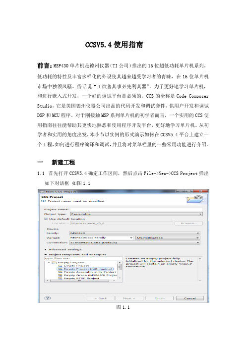
1.1首先打开CCSV5.4确定工作区间,然后点击File->New->CCS Project弹出 如下对话框如图1.1
图1.1
1.2在 Project name中输入新建工程的名字,在此输入lesson24。
1.3在Output type中有两个选项:Executable和Static library,前者为构建一个完整的可执行程序,后者为静态库。在此保留:Executable可执行程序
3.2.8 Restart
点击该按钮将程序指针指向程序的起始位置,即程序第一行。
3.3 设置断点
在调试的过程中,我们可以借助断点帮助调试。断点的作用是使程序在设置断点的地方停下来。
选择需要设置断点的位置:
方法一:在需要设置断点的那一行,右键选择Breakpoint->Breakpoint,显示断点 。
图2.3
如图示,程序没有错误,如果程序有错,该窗口会显示错误信息,根据错误显示修改程序,重新进行编译,直至无错方可进行调试。
三 程序调试
3.1 在编译无错后,点击工具栏类似昆虫按钮 进行调试,调试窗口如图3.1
(注:如果调试窗口没有出来,点击View->Debug)
图3.1
3.2 Debug窗口功能介绍
1.4在Location中选择存储路径,在此选择默认路径F:\workspace_v5_4。
MSP430G2xx3设备的SMBus库用户指南说明书

SMBus Library for MSP430G2xx3Devices User’s GuideDOCNUM-1.10.00.00Copyright©2015T exas Instruments Incorporated.1 CopyrightCopyright©2015Texas Instruments Incorporated.All rights reserved.MSP430and MSP430Ware are trademarks of Texas Instruments Instruments. ARM and Thumb are registered trademarks and Cortex is a trademark of ARM Limited.Other names and brands may be claimed as the property ofbe aware that an important notice concerning availability,standard warranty,and use in critical applications of Texas Instruments semi-conductor products and disclaimers thereto appears at the end of this document.Texas Instruments13532N.Central Expressway MS3810Dallas,TX75243/Revision InformationThis is version1.10.00.00of this document,last updated on Fri Feb13201511:59:44.Table of Contents2Table of ContentsCopyright (1)Revision Information (1)1Introduction (3)1.1Introduction (3)1.2SMBus (3)1.3The MSP430™SMBus Library Package (4)2Introduction to the MSP430™SMBus API (5)2.1Overview (5)2.2Supported Device Families (5)2.3Supported Development Environments (5)2.4Stack Organization (5)2.5Usage of MCU Peripheral Resources (6)2.6Release Notes and Migration from Previous Versions (6)3SMBus API Usage (7)3.1Introduction (7)3.2Usage (7)3.3Examples (8)IMPORTANT NOTICE (9)1Introduction1.1IntroductionThs SMBus(Sytem Management Bus)API(application programming interface)stack forMSP430™microcontrollers is a turnkey API.It includes support for applications where theMSP430™microcontroller is acting as the master or a slave.The API is designed to minimize the SMBus knowledge required to write an application:All SMBus protocol is handled automatically by the APIThe data interface presented to the application is simple to use,abstracting the applicationfrom SMBus protocolThe user should not need to modify the API source.However,for experienced developers,thesource is open and available for editing.Accessing the API’s source can also be useful for systemdebug.Application examples are included in the MSP430™SMBus Library Package.1.2SMBusThe System Management Bus(SMBus)is a lightweight two-wire interface based on the principlesof I2C,commonly used as a control bus and for power management tasks in computing,mobilecomputing and battery operated applications.A device performing data transfers on the bus canbe considered a master,which is the device which initiates a transaction and drives the clock,or aslave,which is the target of a SMBus transaction driven by the master.Both the master and theslave can act as transmitters or as receivers.SMBus2.0shares a lot of similarities with I2C,but some of the most relevant differences include:Time-out detection when a device stretches the clock for too longPacket Error Checking(PEC)can be optionally appended at the end of each transaction,allowing the bus to automatically validate packetsI2C only defines a PHY and Data-Link layers,but SMBus defines a network layer withdifferent SMBus protocols which can be used to exchange data between devicesOptional use of additional lines such as SMBAlert#and SMBSUS#.For more information about SMBus,please refer to the SMBus2.0specification:/specs/.For more information about I2C,please refer to/documents/user manual/UM10204.pdf1.2.1Supported FeaturesThe following table details the SMBus features supported in the MSP430™SMBus library.SMBus Feature MSP430FR5xx6xx MSP430G2xx3Applicable SMBus2.0 Master Slave Master Slave specification sectionClock Timeout detection1Y es Y es Y es1Y es1 3.1.1.2Manual NACK on invalid address/data N/A Y es2N/A No 4.2Arbitration Y es N/A Y es N/A 4.3.2Clock stretching Y es Y es Y es Y es 4.3.3Multiple Slave address N/A No N/A No 5.2General Call address N/A No N/A No 5.2PEC Y es Y es Y es Y es 5.4Quick Command Partial3Partial3Parial3Partial3 5.5.1Send Byte Y es Y es Y es Y es 5.5.2Receive Byte Y es Y es Y es Y es 5.5.3Write Byte/Word Y es Y es Y es Y es 5.5.4Read Byte/Word Y es Y es Y es Y es 5.5.5Process Call Y es Y es Y es Y es 5.5.6Block Write/Read Y es Y es Y es Y es 5.5.7Block write-block read process call Y es Y es Y es Y es 5.5.8Host notify protocol No No No No 5.5.9ARP No No No No 5.6SMBAlert#No No No No Appendix ASMBSUS#No No No No Appendix ANotes:1.MSP430G2xx3USCI doesn’t have integrated timeout detection and requires a timer2.MSP430FR5x/6xx can optionally-use DMA to stretch SCL while deciding to ACK/NACK thecurrent byte3.Only QuickCommand Write is supported,not QuickCommand Read1.3The MSP430™SMBus Library PackageThis User’s Guide documents the SMBus API and examples.The contents of the package isdescribed below:smbuslib:T op level directory.Contains release notes and the manifestfile related to licensing.•docs:Contains the API and User’s Guides for the supported MSP430™devices•driverlib:Contains the standard MSP430™driverlib which is used in the libraryimplementation for device families that support driverlib(for example,MSP430FR5xx6xx)•examples:Contains the example projects for each of the supported MSP430™devices•src:Contains the source code for the SMBus Library stack2Introduction to the MSP430™SMBus API 2.1OverviewThe MSP430™SMBus API stack allows easy creation of MSP430™applications thatcommunicate with other system components over a SMBus interface.This API supports using the MSP430™microcontroller as the SMBus master or as a SMBusslave.2.2Supported Device FamiliesThe SMBus API stack is supported on the following MSP430™device families:MSP430FR5xx6xxMSP430G2xx32.3Supported Development EnvironmentsThe SMBus API stack and examples build and run on both the IAR and CCS environments forMSP430™microcontrollers.See the Release Notes HTMLfile in the SMBus Library Package forspecific IAR/CCS version information.IAR and CCS are both available in free,code-size-limited versions(8K and16K,respectively,ofobject code).Applications thatfit under8K of memory can be run on both free versions.Applications that are greater than8K cannot be built using the free IAR Kickstart tool.Instead,thefree version of CCS can be used;or a licensed version of either environment.See the Release Notes within the SMBus Library Package zipfile for additional informationspecific to a given release.2.4Stack OrganizationThe software stack is organized into three layers:The public API layer defines the API’s that should be called by application programs.Thesefunctions are defined in smbus.h.The network layer manages the SMBus protocol state machine and interfaces with thephysical layer.These functions are defined in smbus nwk.h and should not be called directlyfrom application programs.The physical layer contain all the device specific code to interact with the MSP430™microcontroller.These functions are defined in smbus phy.h and should not be called directlyfrom application programs.2.5Usage of MCU Peripheral ResourcesWithin the SMBus API,the resources shown below are considered owned by the API.If theapplication accesses them,it should be aware of how the API uses them.2.6Release Notes and Migration from Previous VersionsA Release Notes HTMLfile accompanies each release of the SMBus Library Package.Referencethisfile for any information specific to this release,including:All changes from the previous versionsInstructions for migration from previous versionsUpdated IDE configuration informationKnown issues3SMBus API Usage3.1IntroductionThis chapter contains the detailed documentation for the application API functions anddescriptions on using the API to create a SMBus master or slave application.3.2UsageThis section illustrates the basic application template for master and slave applications.See theexamples for complete applications,and the HTML API documentation for details on theindividual APIs.3.2.1Master Usage Outline//Declare master SMBus structureSMBus SMB;//Initialize GPIOs and clocks...//Initialize GPIO I2C pins...//Initialize SMBus Master always at100kbps per SMBus specSMBus masterInit(&SMB,NULL,(MCLK MHZ*1000000));//Initialize I2C and enable SMBus InterruptsSMBus masterEnableInt(&SMB);//Send SMBus Sendbyte command(0x33)uint8t ret=SMBus masterSendByte(&SMB,//SMB struct0x40,//Slave Addr0x33);//SMB Command...3.2.2Slave Usage Outlinemain(){//Declare slave SMBus structureSMBus SMB;//SMBus receive and transmit buffersuint8t au8RxBuff[SMB MAX PACKET SIZE];uint8t au8TxBuff[SMB MAX PACKET SIZE];//Initialize GPIOs and clocks...//Initialize GPIO I2C pins...//Initialize SMBus SlaveSMBus slaveInit(&SMB,NULL);//Set the slave’s addressSMBus slaveSetAddress(&SMB,0x40);//Set the RX and TX buffers for SMBusSMBus slaveSetRxBuffer(&SMB,au8RxBuff,sizeof(au8RxBuff));SMBus slaveSetTxBuffer(&SMB,au8TxBuff,sizeof(au8TxBuff));//Initialize I2C and enable SMBus InterruptsSMBus slaveEnableInt(&SMB);...while(1){disable interrupt();{BIS SR(LPM3bits+GIE);//Go to sleep}enable interrupt();}//While(1)}#pragma vector=USCIAB0TX VECTOR,USCIAB0RX VECTORinterrupt void USCI ISR(void){//Check the state of SMBusswitch(SMBus slaveProcessInt(&SMB)){case SMBus State Slave QCMD://If a Quick command was detected,execute function(if any)break;case SMBus State Slave CmdComplete://Get command using SMBus slaveGetCommand(&SMB)and process command//if command is not valid/supported//SMBus slaveReportError(&SMB,SMBUS ErrorCode Cmd);LPM3EXIT;//Exit to main loop if requiredbreak;default:break;}//Clear flags to be ready for next packetSMBus processDone(&SMB);}#pragma vector=TIMER1A0VECTORinterrupt void TIMER1A0ISR(void){//Call the SMBUS function to handle a timeout error and restart the SMBUSSMBus slaveProcessTimeoutInt(&SMB);}3.3ExamplesSeveral examples are provided with the release package that illustrate using the library toimplement both SMBus master and slave application.For each example,matching master and slave implementations are provided.ReadByte Echo-sends and echoes back a ReadByte commandWriteWord Dimmer-sends and echoes back a WriteWord commandAllProtocols-sequences through all the SMBus protocolsExamples are configured for the MSP-EXP430G2and MSP-EXP430FR5969launch pad boardsand CCS and IAR projects are provided.9 IMPORTANT NOTICET exas Instruments Incorporated and its subsidiaries(TI)reserve the right to make corrections,modifications,enhancements,improvements, and other changes to its products and services at any time and to discontinue any product or service without notice.Customers should obtain the latest relevant information before placing orders and should verify that such information is current and complete.All products are sold subject to TI’s terms and conditions of sale supplied at the time of order acknowledgment.TI warrants performance of its hardware products to the specifications applicable at the time of sale in accordance with TI’s standard warranty.T esting and other quality control techniques are used to the extent TI deems necessary to support this warranty.Except where mandated by government requirements,testing of all parameters of each product is not necessarily performed.TI assumes no liability for applications assistance or customer product design.Customers are responsible for their products and applications using TI components.T o minimize the risks associated with customer products and applications,customers should provide adequate design and operating safeguards.TI does not warrant or represent that any license,either express or implied,is granted under any TI patent right,copyright,mask work right,or other TI intellectual property right relating to any combination,machine,or process in which TI products or services are used. Information published by TI regarding third-party products or services does not constitute a license from TI to use such products or services or a warranty or endorsement e of such information may require a license from a third party under the patents or other intellectual property of the third party,or a license from TI under the patents or other intellectual property of TI.Reproduction of TI information in TI data books or data sheets is permissible only if reproduction is without alteration and is accom-panied by all associated warranties,conditions,limitations,and notices.Reproduction of this information with alteration is an unfair and deceptive business practice.TI is not responsible or liable for such altered rmation of third parties may be subject to additional restrictions.Resale of TI products or services with statements different from or beyond the parameters stated by TI for that product or service voids all express and any implied warranties for the associated TI product or service and is an unfair and deceptive business practice.TI is not responsible or liable for any such statements.TI products are not authorized for use in safety-critical applications(such as life support)where a failure of the TI product would reasonably be expected to cause severe personal injury or death,unless officers of the parties have executed an agreement specifically governing such use.Buyers represent that they have all necessary expertise in the safety and regulatory ramifications of their applications, and acknowledge and agree that they are solely responsible for all legal,regulatory and safety-related requirements concerning their products and any use of TI products in such safety-critical applications,notwithstanding any applications-related information or support that may be provided by TI.Further,Buyers must fully indemnify TI and its representatives against any damages arising out of the use of TI products in such safety-critical applications.TI products are neither designed nor intended for use in military/aerospace applications or environments unless the TI products are specifically designated by TI as military-grade or“enhanced plastic.”Only products designated by TI as military-grade meet military spec-ifications.Buyers acknowledge and agree that any such use of TI products which TI has not designated as military-grade is solely at the Buyer’s risk,and that they are solely responsible for compliance with all legal and regulatory requirements in connection with such use.TI products are neither designed nor intended for use in automotive applications or environments unless the specific TI products are designated by TI as compliant with ISO/TS16949requirements.Buyers acknowledge and agree that,if they use any non-designated products in automotive applications,TI will not be responsible for any failure to meet such requirements.Following are URLs where you can obtain information on other Texas Instruments products and application solutions:ProductsAmplifiersData ConvertersDLP®ProductsDSPClocks and TimersInterfaceLogicPower Mgmt MicrocontrollersRFIDRF/IF and ZigBee®Solutions amplifi/clockswww.ti-rfi/lprfApplicationsAudioAutomotiveBroadbandDigital ControlMedicalMilitaryOptical NetworkingSecurityT elephonyVideo&ImagingWireless/audio/automotive/broadband/digitalcontrol/medical/military/opticalnetwork/security/telephony/video/wirelessMailing Address:T exas Instruments,Post Office Box655303,Dallas,T exas75265 Copyright©2015,T exas Instruments Incorporated。
MSP430F2XX中文手册(加了标签) 10.通用串口

MSP430F2系列16位超低功耗单片机模块原理第10章通用串口界面Universal Serial Interface 版本: 1.5日期: 2007.5.原文: TI MSP430x2xxfamily.pdf翻译: 陈安都湖南长沙-中南大学编辑: DC 微控技术论坛版主注:以下文章是翻译TI MSP430x2xxfamily.pdf 文件中的部分内容。
由于我们翻译水平有限,有整理过程中难免有所不足或错误;所以以下内容只供参考.一切以原文为准。
详情请密切留意微控技术论坛。
Page 1 of 15通用串行接口模块(USI)提供与硬件模块的SPI和I2C串行通信。
本章讨论这两种模式。
USI模块包含在MSP420X20XX系列中。
主题10.1 USI的介绍10.2 USI的使用10.3 USI的寄存器10.1 USI的介绍USI模块提供支持同步串行通信的基本功能。
一般地,一个8、16位移位寄存器能用来输出数据流,少许的几条指令就可以执行串行通信。
另外,USI包含的内置硬件可以模拟SPI和I2C通信。
USI模块还包括中断,可以进一步减少串行通信的通用程序并且保持MSP430的低功耗特性。
USI模块的特性包括:支持三线SPI模式支持I2C模式可变的数据长度在LPM4方式下不需要内部时钟MSB或LSB指令可选在I2C模式下能控制SCL打开、停止监测在主机模式下的仲裁丢失监测可编程的时钟发生器可选择的钟极性和相位控制Page 2 of 15表10-1展示了SPI模式下的USI模块Page 3 of 15表10-2展示了I2C模式下的USI模块10.2 USI的操作USI模块主要由移位寄存器和位计数器组成,通过逻辑控制来支持SPI和I2C 通信。
USI的移位寄存器为USISR,通过软件直接控制数据的移入和移出。
位计数器计算采样位的数目以及在USICNTX位写零时设置USI中断标志位Page 4 of 15USIIFG。
单片机430 2系列 用户指南1

2.1
Relaxation Oscillator (RO)
The relaxation oscillator method counts the number of relaxation oscillator cycles within a fixed period (gate time), as shown in Figure 1.
© 2011, ቤተ መጻሕፍቲ ባይዱexas Instruments Incorporated
SLAA490 – April 2011 Submit Documentation Feedback
Implementations
The naming convention for the RO method in the library identifies the relaxation oscillator mechanism, the timer used to measure or count oscillations, and the timer used to define the gate period (see Table 1). Table 1. Relaxation Oscillator Naming Convention
(1)
The software library described in this document can be downloaded from /docs/toolsw/folders/print/capsenselibrary.html.
2
Capacitive Touch Library
2
Implementations
For the implementations described in this document, the fundamental principle is that two independent timing domains are compared. One domain is fixed, and the other is variable as a function of the capacitance.
TI MSP430AFE2x3 2x2 2x1 微控制器说明书

MSP430AFE2x3MSP430AFE2x2MSP430AFE2x1 ZHCS136A–NOVEMBER2010–REVISED MARCH2011混合信号微控制器特性•低电源电压范围:1.8V至3.6V•多达3个具有差分可编程增益放大器(PGA)输入的24位三角积分模数(A/D)转换器•超低功耗•具有3个捕获/比较寄存器的16位Timer_A –激活模式:220μA(在1MHz频率和2.2V电压条件下)•串行通信接口(USART),可用软件来选择异步UART或同步SPI–待机模式:0.5μA•16位硬件乘法器–关闭模式(RAM保持):0.1μA•欠压检测器•5种节能模式•具有可编程电平检测功能的电源电压监控器/监视器•可在不到1μs的时间里超快速地从待机模式唤醒•串行板上编程,无需从外部进行电压编程,利用安•16位精简指令集(RISC)架构,高达12MHz系统时全熔丝实现可编程代码保护钟•片上仿真模块•基本时钟模块配置•系列成员汇总于表1。
–带有两个已校准频率的高达12MHz的内部频率•如需了解完整的模块说明,请参阅《MSP430x2xx –内部超低功耗低频(LF)振荡器系列用户指南》,文献编号SLAU144–高达16MHz的高频(HF)晶振–谐振器–外部数字时钟源说明德州仪器(TI)MSP430™系列超低功率微控制器包含几个器件,这些器件特有针对多种应用的不同的外设集。
这种架构与5种低功耗模式相组合,专为在便携式测量应用中延长电池使用寿命而优化。
该器件具有一个强大的16位RISC CPU,16位寄存器和有助于获得最大编码效率的常数发生器。
数字控制振荡器(DCO)可在不到1µs 的时间里完成从低功耗模式至运行模式的唤醒。
MSP430AFE2x3器件是超低功耗混合信号微控制器,集成了三个独立的24位三角积分A/D转换器、一个16位定时器、一个16位硬件乘法器、USART通信接口、安全装置定时器和11个I/O引脚。
MSP430F2XX中文手册(加了标签) 12.SPI 串行同步通讯模式
Page 4 of 14
MSP430 F2 系列超低功耗单片机模块原理 第 12 章 串行同步通讯模式 SPI
微控设计网
图12-2 通用串行通信接口主机和从机
图12-2说明了USCI在3线和4线模式下作为主机时的配置。当数据被送到传输数据缓冲器 UCxTXBUF时,USCI开始数据传送。当TX移位寄存器空了后,UCxTXBUF缓冲区的数据被传送到其 中, 在UCxSIMO上传送数据, 起始位是最高位还是最低位, 决定于UCMSB标志位的设置。 而UCxSOMI 上的数据在反向跳边沿下移入接收移位寄存器。当字符接收到之后,接收数据从RX移位寄存器 送入接收数据缓冲器UCxRXBUF,并且置位接收中断标志UCxRXIFG,表示接收/发送操作完成。 发送中断标志位UCxTXIFG被置位后,表明数据已从UCxTXBUF缓冲区进入TX移位寄存器, UCxTXBUF寄存器已经为发送新数据做好准备,但并不意味着传送和接收的完成。 为了在主机模式下接收USCI数据,数据必须事先写入UCxTXBUF,因为接收和发送操作不是 马上进行的。 4线SPI主机模式 在4线主机模式中,UCxSTE用来防止与其它主机相冲突并象表12-1描述的那样控制主机。当 UCxSTE处于主机不活动状态时: UCxSIMO 和 UCxCLK设置为输入,不再驱动总线。 出错位UCFE置位,表明在通讯的完整性上,使用者未按照规则操作。 内部状态被复位时,移位操作取消。 如果数据写入UCxTXBUF而主机通过UCxSTE位保持非工作状态, UCxSTE转换为主机工作状态, 数据立即被发送。如果一个正在工作的发送过程,因UCxSTE转换为主机不运行状态而取消时, 当UCxSTE转向主机运行状态时数据需要被重新写入UCxTXBUF。 UCxSTE输入信号不能应用3线主机 模式。 12.3.4 从机模式
MSP430初学者教程(最详细)
如何学习学习就是迎接挑战、解决困难的过程,没有挑战,就没有人生的乐趣。
下面以系列为例,解释一下学习的过程。
(1)获取资料购买有关书籍,并到杭州利尔达公司网站和TI网站获取资料,例如,在网上可以找到FET 使用指导、F1xx系列、F4xx系列的使用说明和具体芯片的数据说明,可以找到FET的、实验板、知识等大量的实际应用参考电路,当然有些资料是英文的,看懂英文资料是个挑战,学会4、6级英语就是为看资料的。
英语难学,但是看资料容易,只要下决心,看完一本资料,就可以看懂所有的相关资料。
(2)购买FET和实验电路板如果经济条件不错,可以直接购买。
(3)自制FET和实验电路板自制仿真器FET,首先要到网上找到FET,然后就可以使用画电路板软件画电路图和电路板图,这又是个挑战。
FET电常简单,但要把它制作出来还是需要下一番工夫的,找一本有关书,然后练习画,画完后,就学习认识,再购买元件,这时就可以画电路板图了,一旦画好,将形成的PCB文件交给公司,10天后,就可以得到电路板,焊上元件和电缆,等实验电路板做好后,就可以与实验电路板一起调试了。
自制实验电路板,需要单片机芯片内部工作原理的知识、封装知识,清楚的知道每一个的功能,还需要、按钮、、三端、、散热器、、普通电容、电阻、等元件的知识,对于初学者,可以做一个只有3个、8个按钮、8个的简单实验板,这样的实验板,虽然简单,但足可以帮助初学者入门单片机。
自制实验电路板与自制FET一样,首先画电路图,然后买元件,再画电路板。
由于系列芯片是扁平封装,焊接起来有一定难度,这好象是个挑战,但实际上很简单,方法如下:首先在焊盘上涂上,在未干的情况下,将芯片放在焊盘上,注意芯片第一的位置,并使与焊盘对齐,将擦干净的(不能有任何)接触引脚,引脚只要一热,焊盘上的就自动将引脚焊住了,千万注意上不能有,焊接时最好配备一个。
焊接电路板时,每一个元件都要核对参数,可以用万用表测量的元件一定要测量。
MSP430F2XX中文手册(加了标签) 5.Flash块控制器
Page 1 of 18MSP430F2系列16位超低功耗单片机模块原理第5章 Flash 块控制器版本: 1.3日期: 2007.6.原文: TI MSP430x2xxfamily.pdf翻译: 余川编辑: DC 微控技术论坛版主注:以下文章是翻译TI MSP430x2xxfamily.pdf 文件中的部分内容。
由于我们翻译水平有限,有整理过程中难免有所不足或错误;所以以下内容只供参考.一切以原文为准。
详情请密切留意微控技术论坛。
第五章 Flash 存储控制器本章介绍了MSP430x2xx 系列单片机Flash 存储控制器的操作。
5.1 Flash 存储器的介绍Page 2 of 18 5.2 Flash 存储器的分段结构5.3 Flash 存储器的操作5.4 Flash 存储器的控制寄存器5.1 Flash 存储器的介绍MSP430 的F lash 存储器是可位/字节/字寻址和编程的存储器。
该模块由一个集成控制器来控制编程和擦除的操作。
控制器包括三个寄存器,一个时序发生器及一个提供编程/擦除电压的电压发生器。
MSP430 的F lash 存储器的特点有:● 产生内部编程电压● 可位/字节/字编程● 超低功耗操作● 支持段擦除和多段模块擦除F lash 存储器和控制器的结构框图如图5−1所示。
注意:F lash 写入和擦除操作期间的最小电压值V CC 应为2.2V 。
如果在操作期间V CC 低于2.2V ,写入或擦除的结果将是不确定的。
图5−1 F lash 存储器框图Page 3 of 185.2 Flash 存储器的分段结构MSP430 F lash 存储器分成多个段。
可对其进行单个位/字节/字的写入,但是最小的擦除单位是段。
F lash 存储器分为主存储器和信息存储器两部分,在操作上两者没有什么区别,程序代码和数据可以存储于任意部分。
两部分的区别在于段的大小和物理地址。
信息存储器有四个64字节的段,主存储器有两个或更多的512字节的段。
MSP430入门详细讲解不错的入手机会
引脚使用举例
控制连接在P5.1口线的发光二极管的亮与熄: 首先、 P51为输出 亮 输出1 熄灭 输出0 ---P5DIR =0x0 2; ---P5OUT = 2 ; ---P5OUT = 0 ;
南京航空航天大学电子中心&TI南航430联合实验室
如何让发光二级管闪烁?
1、亮 2、延时1秒钟 3 3、熄灭 4、延时1秒钟 5、跳转到 步骤1 (演示)
串行密码锁设计
按照顺序:KEY0-KEY1-KEY2 ; KEY1-KEY0-KEY2 ; K0-K0-K0-K1-K2-K0-K2 ; K2-K2-K0-K1-K2 ; 错误状态的清除 很重要!!
南京航空航天大学电子中心&TI南航430联合实验室
如何让单片机发声?
声音是什么? ——声音是震动产生的; 扬声器发声的原理:处在磁场中的有电 流的线圈产生震动,继而发声。 不同的频率产生不同的声音; MSP430的端口可以输出不同的频率; 继而可以推动扬声器产生不同的声音。 下页的程序将发出什么声音呢?
指针类型 18E-38— 39E+38 18E-38— 39E+38 浮点类型
表达式语句(结构) 表达式语句(结构)
条件语句 开关语句 循环语句 返回语句
南京航空航天大学电子中心&TI南航430联合实验室
条件语句
语句表达形式有3种(a、b、c): a if(条件表达式) 语句 b if(条件表达式) 语句1 else 语句2 c if(条件表达式) 语句1 else if(条件表达式) 语句2 else if(条件表达式) 语句3 ……
第二段程序
void s1(void) { for(ff=30;ff<500;ff++) { P6OUT ^= BIT0; // 对输出置反 for(tmp=0;tmp<ff;tmp++); // 延时 } }