粮库冷却机电气控制系统设计说明书
制冷设备的电气控制系统(好)资料

PTC启动器的内部结构
(2)PTC启动器工作原理
第 六 章 制 冷 设 备 的 电 气 控 制 系 统
(a) PTC启动继电器接线图
(b) PTC启动器的电阻-温
度关系曲线
在使用应注意:由于PTC启动器的热惯性,压缩机每次起 动后,必须间隔2~3分钟后才能再次启动。
过电流过温升保护继电器
(1)过电流过温升保护器结构特点
第 六 章 制 冷 设 备 的 电 气 控 制 系 统
第 六 章 制 冷 设 备 的 电 气 控 制 系 统
(2)碟形热控过电流、过温升保护器工作原理
图6-13
碟形热控过电流、过温升保护继电器接线图
埋置式温度保护器
第 六 章 制 冷 设 备 的 电 气 控 制 系 统
其他保护器继电器
第 六 章 制 冷 设 备 的 电 气 控 制 系 统
(2)进行开路试验
第 六 章 制 冷 设 备 的 电 气 控 制 系 统
(3)进行短路试验
(4)对设备的对地绝 缘性能测量
(5)对设备绕组间的绝缘性能测量
第 六 章 制 冷 设 备 的 电 气 控 制 系 统
(6)处理后的“放电”工作
第 六 章 制 冷 设 备 的 电 气 控 制 系 统
图6-2
6-6
电磁换向阀的结构和修理
(1)电磁换向阀的工作制冷原理
第 六 章 制 冷 设 备 的 电 气 控 制 系 统
(2)电磁换向阀的工作制热原理
第 六 章 制 冷 设 备 的 电 气 控 制 系 统
电冰箱的电气控制线路
第 六 章 制 冷 设 备 的 电 气 控 制 系 统
(1)只有过电流保护装置的原理图
(3)罩极式电动机
粮油储藏谷物冷却机应用技术规程

粮油储藏谷物冷却机应用技术规程1.粮油储藏谷物冷却机主要用于降低谷物的温度,以延长储存时间。
The grain and oil storage grain cooling machine is mainly used to reduce the temperature of the grain to extend the storage time.2.冷却机应具备自动控制系统,能够根据谷物的温度自动调节风速和湿度。
The cooling machine should have an automatic control system that can automatically adjust the air speed and humidity based on the temperature of the grain.3.冷却机应具备风阻小、风量大的特点,以保证谷物能够均匀受热。
The cooling machine should have the characteristics of low wind resistance and high air volume to ensure that the grain can be evenly heated.4.冷却机应定期进行清洁和维护,以确保其正常运行。
The cooling machine should be cleaned and maintained regularly to ensure its normal operation.5.冷却机的温度控制精度应在±1摄氏度以内。
The temperature control accuracy of the cooling machine should be within ±1 degree Celsius.6.冷却机应具备过热、过载、短路等保护功能,确保设备运行安全。
The cooling machine should have overheat, overload, short circuit and other protection functions to ensure the safe operation of the equipment.7.冷却机应采用先进的节能技术,降低能耗,减少运行成本。
柴油发电机组的冷却系统说明书

柴油发电机组的冷却系统说明书1. 简介柴油发电机组是一种常见的发电设备,通过燃烧柴油产生动力,驱动发电机发电。
在发电过程中,机组需要保持合适的温度,以确保发电机组的正常运行。
本说明书将详细介绍柴油发电机组的冷却系统,包括系统组成、工作原理和注意事项。
2. 冷却系统组成柴油发电机组的冷却系统通常由以下几个主要组成部分构成:2.1 散热器:散热器是冷却系统中的核心部件,用于将柴油发电机组内部产生的热量散发到周围环境中。
散热器通常由多个散热管组成,通过流体循环使冷却水与热量交换。
散热器应保持良好的通风条件,以确保散热效果。
2.2 水泵:水泵用于循环冷却水,将热量带出发电机组并送至散热器。
水泵需保持良好的运转状态,确保冷却水循环畅通,防止过热现象。
2.3 水箱:水箱是储存冷却水的容器,供给冷却系统使用。
水箱应具备足够的容量,以满足冷却系统对冷却水的需要,并具备防漏功能。
2.4 温度传感器:温度传感器用于监测柴油发电机组的冷却水温度。
通过实时监测温度的变化,可以及时调整冷却水的循环速度,确保发电机组的正常工作。
3. 工作原理柴油发电机组的冷却系统工作原理如下:3.1 冷却水循环:水泵将冷却水从水箱中抽出,并通过管路输送至散热器。
在散热器中,冷却水与发电机组产生的热量进行交换,吸收热量后再由水泵送回发电机组,形成循环。
通过不断循环,冷却水能够稳定地保持发电机组的温度。
3.2 温度控制:温度传感器检测到冷却水温度超过设定范围时,会发送信号给控制系统。
控制系统根据信号调整水泵的转速,使冷却水的循环速度加快或减慢,以达到控制温度的目的。
通过温度控制,发电机组的温度得以稳定,避免过热或过低温度对机组的影响。
4. 注意事项在使用柴油发电机组的冷却系统时,需要注意以下事项:4.1 定期维护:定期检查散热器、水泵及水箱等组成部分的状态,并及时清洗或更换损坏的部件,确保冷却系统的正常运行。
4.2 水质管理:使用纯净水或经过处理的水作为冷却水,避免因水质问题导致冷却系统结垢或腐蚀。
冷库制冷系统设计及管理要求_标准__概述及解释说明

冷库制冷系统设计及管理要求标准概述及解释说明1. 引言1.1 概述冷库制冷系统是指通过特定的设备和技术手段,将冷库内的温度降低到低于周围环境温度,以实现食品、药品等货物的低温存储和保鲜。
制冷系统设计及管理要求是确保冷库制冷系统正常运行、高效工作的关键因素。
本文旨在介绍冷库制冷系统设计及管理要求的标准,并对其进行全面解释说明。
1.2 文章结构本文主要分为五个部分:引言、冷库制冷系统设计要求、冷库制冷系统管理要求、冷库制冷系统相关标准概述和结论。
引言部分将对文章进行概述,介绍该领域的背景和意义,并概述文章的结构。
接下来的各个部分将详细探讨与解释不同方面的内容,最后进行总结并给出未来发展展望和建议。
1.3 目的本文旨在深入了解和解释关于冷库制冷系统设计及管理要求相关的标准,包括设计原则、参数考虑因素、运行监控管理以及维护保养要求等。
通过深入理解这些标准,可以提高冷库制冷系统的设计水平和管理效率,确保其正常运行和可靠性。
同时,我们也将对国内外相关标准进行概述和比较分析,为技术人员和管理者提供参考依据,并为未来发展方向提出建议。
2. 冷库制冷系统设计要求:2.1 制冷系统概述在冷库的制冷系统中,主要包括压缩机、蒸发器、冷凝器、膨胀阀以及管道等组件。
通过循环利用制冷剂完成热量的吸收和释放,从而实现对冷库内部温度的控制。
2.2 设计原则和要点在进行冷库制冷系统设计时,需要考虑以下原则和要点:2.2.1 区分不同温度区域:根据冷库内部存放物品的不同需求,对其划分为不同的温度区域,确保不同区域的温度能够满足物品储存要求。
2.2.2 效率与节能:选用高效节能的制冷设备和材料,并结合科学合理的运行策略,以提高整体系统的能效比并降低能耗。
2.2.3 安全性:确保制冷系统运行时无泄漏和安全隐患,并设置适当的安全装置以应对紧急情况。
2.3 设计参数和考虑因素在进行设计时需要考虑以下参数和因素:2.3.1 温度范围:根据冷库内存放物品的特性和要求,确定设计温度范围。
精创冷库ecm-30说明书

精创冷库ecm-30说明书1、冷库设备安放在通风良好的干燥洁净环境中。
禁止在易燃、易爆、易腐蚀、有破坏绝缘的气体和导电尘埃的环境中使用本设备,禁止在不安全或有安全隐患的环境中使用本设备。
2、应有足够的空间进行冷库设备的安装,地面用混凝土抹面找平,基础耐力不小于10Tm 2。
地面预留排水孔或槽。
3、冷库设备使用的电源为三相四线380V50Hz ,检查所使用的电源是否与设备配套。
线载负荷是否符合要求而满足设备的的正常运行。
并配备冷库专用电闸。
4、冷库设备一般配用风冷式冷凝器,不需要用水,特别适用于边远地区和缺水地区使用。
(特殊情况下可用水冷式冷凝器>5、冷库设备应有专人负责看管。
并了解用电常识和熟悉冷库的基本构造、性能。
冷库内放置的物品应留有一定的空隙,以利于冷气的流动。
冷库的制冷机组周围严禁堆放物体并远离发热源,以利于空气流动而充分散热,并定期用软毛刷清除制冷机组、散热器上的灰埃。
这些都是为了确保散热。
冷库的库温设定应在规定的范围内,否则会增加冷库的工作负荷而损坏冷库元件。
储藏保鲜库库内温度设定在0+5 ℃,冷冻库库内温度设定在0到18℃,低温库库内温度设定在0到23 ℃。
其它参数的设定请参考说明书。
应尽量减少冷库的开门次数,并确保关门严密,进出货物时应尽量缩短时间,以减少冷量的损耗而节约电力。
观察电源电压的波动是否在规定的范围内。
经常观察冷库运行时的噪声有无异常。
制冷机组上的冷凝器风机是吸风散热(风向朝压缩机方向吹),经常观察风机的转向是否正确(三相电源的改变会改变风机的转向〉,风机转向不正确会导致制冷下降、缩短制冷机的使用寿命。
特别提醒用户:当冷库内有人,而冷库门却被外面的人关上时,冷库里的人不要心慌,当你靠近冷库门时会很快发现冷库门的紧急制动把手,用力向外推即可打开冷库门。
(完整word版)河北工程-冷库检测与控制系统设计(word文档良心出品)

信息与电气工程学院课程设计说明书(2015/2016学年第一学期)课程名称:测控系统工程设计题目:冷库检测与控制系统设计专业班级:学生姓名:学号:指导教师:王静爽王巍安宪军侯帅设计周数:2周设计成绩:2015年1月7日目录1 课程设计目的 (1)2 虚拟仪器简介 (1)3 设计任务及要求 (2)3.1 设计任务 (2)3.2 设计要求 (2)4 冷库检测与控制系统的设计 (2)4.1 设计原理 (2)4.2数据采集卡 (3)4.3软件设计 (3)4.3.1 前面板的设计 (5)4.3.2 后面板的设计 (6)4.4 调试及运行结果 (6)5 课程设计心得体会 (7)6 参考文献 (7)7 指导教师评语 (8)1 课程设计目的课程在教学计划中的地位和作用《虚拟测试技术与仪器课程设计》是为测控专业《虚拟测试技术与仪器》课程而开设的课程设计教学环节,其目的在于培养我们综合运用理论知识来分析和解决实际问题的能力。
通过课程设计能进一步锻炼学生在虚拟测试技术与仪器应用方面的实际工作能力。
我们要着重学会面对一个实际问题,如何去自己收集资料,如何自己去学习新的知识,如何自己去制定解决问题的方案并通过实践不断地去分析和解决前进道路上的一切问题。
虚拟仪器是随着计算机技术、电子测量技术和通信技术发展起来的一种新型仪器。
在国外,虚拟仪器技术已经比较熟了,由于其很强的灵活性,使得该技术非常适用于现代复杂的测试测量系统中。
近几年,虚拟仪器技术在国内的发展势也越来越受到重视。
成熟的虚拟仪器技术由三大部分组成:高效的软件编程环境、模块化仪器和一个支持模块化I/O集成的开放的硬件构架。
该课程设计的目的就是,通过一些功能简单的仪表系统的设计,要在这三个方面上有更深一步的了解。
2 虚拟仪器简介虚拟仪器的90年代提出的新概念。
虚拟仪器(Virtual Instrument,缩写为VI)就是在通用计算机上加上一组软件或硬件,使得使用者在操作这台计算机时,就像是在操作一台自己设计的专用的传统的电子仪器,其实质的充分利用计算机来实现和扩展传统仪器功能。
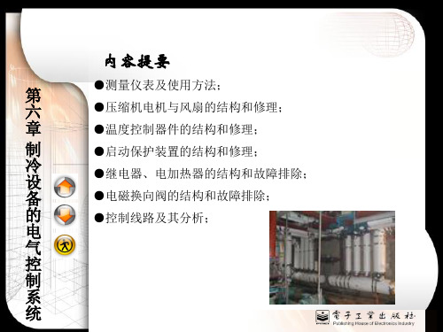
制冷设备的电气控制系统好概要ppt
设计方案
控制器选择
根据制冷设备的性能要求和成本预算,选择合适的控制器,如 PLC、单片机等。
传感器布局
根据设备运行需要,合理布局各种传感器(如温度、压力等), 实现对设备运行数据的实时监测。
执行器选型
根据制冷设备的制冷剂类型和操作要求,选择适合的电动阀、泵等 执行器。
系统调试
调试步骤
按照先局部后整体的调 试顺序,对制冷设备的 电气控制系统进行调试 。
对于噪音水平过高的问题,可以优化机械结构设计, 降低设备运行时的噪音。
07
本季度制冷设备的电气控制系统优化 和改进建议
控制算法优化
01
采用更先进的控制算 法
如PID控制器、模糊逻辑控制器等, 提高系统的稳定性和响应速度。
02
优化控制逻辑
简化控制流程,减少不必要的运算和 判断,提高控制效率。
03
引入模型预测控制
故障排查
根据调试过程中出现的 故障现象,进行故障定 位和排查,确保系统的 稳定性和可靠性。
性能测试
在调试完成后,进行性 能测试以确保制冷设备 的电气控制系统达到预 期的性能指标。
06
上季度实际控制效果与设计指标差异 分析
控制效果评估
温度波动范围
评估制冷设备的温度波动范围是否 在预设范围内,以及是否稳定。
执行器
作用
执行器是制冷设备电气控制系统的最终执行机构,主要负责接收控制器的控制信 号,驱动制冷设备的各种电动部件,如压缩机、冷凝器、蒸发器等,以达到控制 温度的目的。
类型
执行器主要分为电动阀、电动泵、冷却塔风机等,根据不同的制冷设备和控制需 求,选用不同类型的执行器。
03
控制算法
PID控制
控制储存粮油温度
【相关知识】
(二)对隔热材料的要求
1.导热系数小 这是选择隔热材料应首先考虑的。 一般低温库中使用的隔热材料导热系数应在0.024 ~0.14 w/m·℃ 之间,以保证其隔热性能。 2.容重小 容重小于1000 kg/m3的建筑材料称 为隔热材料或保温材料。
3.材料本身不易燃烧或可自熄。
4.机械强度高 这主要是对预制板材的、沉陷和剥落等现象。
(5)谷物冷却机出风温度的设置一般不宜低于10 ℃。过低的温度设置不能使冷却速度加快,反而造 成运行成本的提高。同时,严禁向仓内送入高于粮 食温度的热空气,以防粮食结露引起霉变。当采用 不同温度分阶段冷却通风时,不允许后阶段通风温 度高于前阶段。
【注意事项】
(6)设备运行过程中,若发现输出冷风温湿度波 动较大或与设定值偏差较大(与设定温度的差值大 于1℃或设定湿度的差值大于6%)时,以及粮食 水分变化较快时,应及时调整和纠正温湿度参数设 定值。若设备自控调节不利或不能纠正偏差时,必 须停机检查原因,排除故障后方能重新启动。
控制储存粮油温度
第十三章第一节 (P415)
学习目标和学习重点
学习目标 通过对本节的学习,能够通过采取不同
手段控制储藏过程中粮油种子的温度,从 而使粮油种子在适宜的环境条件下安全度 过储藏期。 学习重点
系统掌握《谷物冷却机低温储粮规程》 和《储粮机械通风技术规程》的主要内容
一、使用谷物冷却机降低储粮温度
(四)冷却通风的作业要求
(1)对计划低温储藏的粮食,入仓后的非低温粮 应尽快完成初冷作业。
(2)安全水分粮食初冷作业应将粮温降低到12 ~15℃,偏高水分粮应将粮温降低到10~12℃ 。在粮温回升到17~20℃左右时可进行复冷作 业。
(3)冷却通风应尽量在高温天气到来之前完成作 业。高温季节确需进行冷却通风时,应尽量选择 夜间或其他有利的气候条件进行。
冷库设计课程设计-冷库课程设计说明书
冷库设计课程设计:冷库课程设计说明书专业课程设计说明书课题名称:北京某单位小型冷库设计指导教师:职称:教授学生姓名:学号:专业:热能与动力工程学院:机械工程学院摘要本课程设计是北京地区某单位能够冷藏鱼、肉、禽类食品的小型组合式冷库。
设计中关于冻结容积、冷藏容积、冷库类型选择、库板传热系数计算、库房冷耗量计算、冷却设备和制冷压缩机选择等方面进行有关计算及选型。
通过对该冷库冷却系统进行布置,能够满足课题的有关要求,同时在平面布置进行了优化设计及计算,使该冷库设计能够适应课题的有关要求,为系列冷库设计提供有价值的参考。
关键词冷库;冷却系统;平面布置目录摘要 II 目录….. 1 第 1 章冻结库、冷藏库容积的确定 2 设计任务: 2 1.1 冻结库容积的确定 2 1.2 冷藏库容积的确定 3 第 2 章冷库类型的选择 4 第3章库板传热系数的计算 5 第4章库房耗冷量的计算 6 4.1 渗入热的计算 6 4.2食品热的计算 7 4.3操作热的计算 8 4.3.1动力热的计算 8 4.3.2开门渗入热的计算 10 第5章冷却设备和制冷压缩机组的选择 12 5.1 冷却设备的选择 12 5.2 制冷压缩机组的选择 13 总结 17 参考文献 18 致谢 19 第1 章冻结库、冷藏库容积的确定设计任务:北京地区某单位需建造一个带冻结食品能力的小型冷库。
冷藏食品主要是鱼肉禽类,规定的冷藏量是40t,冻结量每天4t,冻结时间为10h,要求的冷藏温度为-18℃,冻结温度为-24℃。
试为该单位设计一个满足上述要求的小型冷库。
1.1 冻结库容积的确定由设计任务知道该小型冷库不仅要求冷藏食品而且还要求冷冻食品,所以该小型冷库应由冻结库和冷藏库组成。
考虑到单位的冷库进食品种类较多,冻结库容积按设有搁架的公式计算(1-1)式中: =4000kg/d ; =10h;——搁架利用系数。
取=0.9;——鱼肉盘面积。
取;——每盘食品净重。
电气控制系统设计与处理装置说明书
The Electric Control System for Part Handling Device GuangZhen Cheng 1, a , Xiang PEI 2, b , Qian Zhou 1, c , ShiYang Wei 1,d1 Huzhou Teachers College, Huzhou, 313000, P.R. China2Henan Polytechnic Institutes, Nanyang 473000, P.R. Chinaa****************, b ***************, c *****************,d *****************Keyw ords: Electric Control; Handling Device; Ladder Diagram, PLC ProgramAbstract. Design content includes the choice of controller, design of external wiring, design of PLC programming. According to the movement process, write PLC program. The program has four components, the initialization program, the manual operation program, the automatic return to the origin program, and automatic working program. Simulating and debugging the program. The work piece on stepping conveyor was moved to the processing machine tool worktable. The device can work in succession, improve working environment, reduce labor intensity, and improve the level of automation. IntroductionThis paper introduced an electric control system for part handling device. The handling device was composed of a frame body, a moving device, a horizontal moving oil cylinder YG1, an upper and a lower movable oil cylinder YG2, a clamping oil cylinder YG3, a conveyor, a working table and a stroke switch. The oil cylinder YG1 is fixed on the frame body, and the oil cylinder YG1 piston rod is fixedly connected with the mobile device, which drives the moving device to realize horizontal movement along the guide rail of the mobile device, and the upper and lower moving oil cylinder YG2 is fixed on the moving device. The oil cylinder YG2 piston rod is fixedly connected with the clamping oil cylinder YG3, the oil cylinder YG2 piston rod can be moved up and down to move up and down, and the clamping oil cylinder YG3 drives the clamping block to realize the clamping and loosening. When the automatic modes operate, rely on the travel switch to achieve the action conversion. Travels switch installation location accurate, handling device motion position accurately. This design were installed upper limit position switch SQ0, down limit switch SQ1, left limit travel switch SQ2, right limit travel switch SQ3. The limit switch SQ0, SQ1 is relatively fixed with mobile device. The limit switch SQ2, SQ3 is relatively fixed with frame. The parts detecting switch SQ4 is fixed on the frame body, to ensure that there is no object on the working table, only then the feeding mechanism is allowed to drop and the parts is put into the working table. The structure ofthe handling device was shown in Fig.1.Fig.1 Structure schematic diagram3rd International Conference on Mechatronics and Information Technology (ICMIT 2016)PLC Control ProgramPLC uses Mitsubishi Co's programmable logic controller, the model was 48MR - FX2N. The control panel components layout was shown in Fig.2. The PLC control wiring diagram was shown in Fig.3. The operating mode was selected with rotary switch, when the rotary switch SA were located SA-1, SA-2, SA-3, SA-4, SA-5, the corresponding function is manual, back to the origin, single-step, single-cycle, automatic operation.Three implementation movements of cylinders YG1, YG2, YG3 were by three solenoid YV1, YV2, YV3 controlled. The cylinder YG1 realize moving left and right, the cylinder YG2realize moving up and down. The cylinders YG3 realize clamping and loosening. The cylinder YG3 has two pistons, intermediate into the oil chamber, left and right cavity of the oil return, left piston to move to the left, right piston shifted to the right, release the part; around into the oil chamber, in the midst of the cavity when the oil back, left piston shifted to the right, right piston to move to the left so as to clamp the part.Fig.2 The control panel components layoutFig.3 PLC control wiring diagramFor the initialization of the PLC, manual control, automatic back to origin, the program ladder diagram was shown in Fig.4. The Automatic cycle program ladder diagram was shown in Fig.5. Work Process AnalysisWhen turned on, the knob switch turned to the original position SA2, press the homing button SB5, institutions back into the origin, the feeding mechanism is in the leftmost, uppermost. All s electromagnet YA1, YA2, YA3, YA4, YA5 power off, this state was called in situ. Then the rotary switch turn to the appropriate operating mode, you can start work, the main actions are, the working bodies rise and down, left and right. Clamping device clamp and loosen. When the manual mode, press the corresponding manual button, complete the appropriate action. When the automatic operation mode, press the start button SB6, institutions in accordance with a predetermined program, start automatic work cycle. Automatically work process as follows.Downward movement and clamping. Select the Auto mode, push the start button SB6, the electromagnet YA2 power on, the solenoid YV2 in the right position, For the cylinder YG2 oil gointo the upper chamber and the under chamber return, the piston down until press the limit switch SQ1, electromagnet Y A2 power off, down moment to stop, while the energized electromagnet Y A5 power on, the solenoid YV3 in the left position, For the cylinder YG3 the oil go into the left and right chamber, the intermediate chamber back to the oil, the piston moves to clamp the parts.solenoid YV2 in left position, the cylinder YG2 lower chamber into oil and upper chamber return oil, the piston moves until the pressed limit switch SQ0, the electromagnet Y A1 power off, stop rising, while the electromagnet Y A3 power on, the solenoid YV1 in the right position, the cylinder YG1 left chamber into oil and right chamber return oil, the piston move to right, until the pressed limit switch SQ3, the electromagnet Y A3 power off, right moment stopped.Downward movement and loosen. Stop right at the same time, the electromagnet Y A2 power on, the solenoid YV2 was at right position, the cylinder YG2 upper chamber into oil and the lower chamber back to oil, the piston move down until press the limit switch SQ1, the electromagnet Y A2 power off, down moment stop, while the electromagnet Y A5 power off, the solenoid YV3 was at right position, the cylinder YG3 intermediate go into oil, left and right chamber return oil, the piston moves, the parts was released.Up movement and move to the left. After the released the parts, the electromagnet Y A1 power on, the solenoid YV2 was at left position, the cylinder YG2 lower chamber into oil and upper chamber return oil, the piston up until pressed limit switch SQ0, the electromagnet YA1 power off,the piston stopped rising, while the electromagnet Y A4 power on, the solenoid YV1 was at left position, the cylinder YG1 right chamber into oil and left chamber back to oil, the piston moved left until the pressed limit switch SQ2, the electromagnet Y A4 power off, the piston stopped left, went back into the origin, completed a cycle of work.Next, the electromagnet Y A2 power on, the solenoid YV2 was at right position, the cylinder YG2 upper chamber into oil and under chamber return oil, the piston moved down, the next working cycle started.Conclusion1) The control program has five working mode, that was manual, back to the origin, single step,single cycle and automation. Convenient for installation and debugging, equipment maintenance.2) The initialization program used to set up the origin conditions and the initial state, includingspecial auxiliary relay M8044 set origin position, M8002 used as an execution condition of IST.The source element of IST from X10, means X10~X17 has the functions of the PLC wiring diagram.3) The part detection switch SQ4 was installed on the frame body. To ensure when the feedingmechanism fall to the table, there was no part on the table. To Avoid feeding mechanism collide table.References[1] S.H. Chen: Machinery equipment electrical control (South China University pres, China 2002).[2] Y.S. Fan: Electrical Control and PLC applications (China Electric Power Press, China 2006) (inChinese).[3] Y.J. Jia, D.Y. Zhang, G.Z. Cheng: Applied Mechanics and Materials Vol. 164 (2012) pp344-347.[4] X.Q. Chen, G. L. Jiang and G.Z. Cheng: Advanced Materials Research Vol. 568 (2012) pp43-46[5] Z.Q. Qi. Machine Electrical Control Technolog y(Machinery Industry Press, China 2002).[6] Y.J. Jia and G.Z. Cheng: J. Hydraulic and pneumatic, Sep.2009, pp4-6 (in Chinese).[7] G.Y. Wang, S.W. Li and G.Z. Cheng: J. Coal Mine Machinery, Aug.2007, pp114-115 (inChinese).[8] Y.J. Jia and Y.B.Cheng: Advanced Materials Research Vols. 295-297 (2011) pp 2483-2486.[9] G.Z.Cheng: Automatic grinding machine electrical control system[J] ManufacturingTechnology & Machine, 2011 (9): 81-83.。
- 1、下载文档前请自行甄别文档内容的完整性,平台不提供额外的编辑、内容补充、找答案等附加服务。
- 2、"仅部分预览"的文档,不可在线预览部分如存在完整性等问题,可反馈申请退款(可完整预览的文档不适用该条件!)。
- 3、如文档侵犯您的权益,请联系客服反馈,我们会尽快为您处理(人工客服工作时间:9:00-18:30)。
摘要 随着粮食流通体制的改革和城乡人民生活水平的不断提高,市场和消费者对粮食质量的优劣更为关心。粮食的品质直接关系到人们的身体健康和市场价格,同时也对我国的粮食储备技术现代化提出了更高的要求,低温储粮是指通过自然或机械的方法,使粮堆温度长期保持15℃或20℃以下,从而降低粮食的呼吸强度, 抑制害虫和微生物的生长,减少粮食的损失,延缓粮食品质劣变,达到安全保存和保鲜的目的。 低温空调储粮的发展最初是采用水冷机组加末端空气处理空调系统, 调节仓库空气温度, 间接降低袋装储粮温度, 并要对粮仓进行隔热处理。然而其一次性投资大,冷却效率低,因此一种一次性投资较小机动性较强的冷却设备一一粮库冷却机运应而。 利用冷粮库却机进行低温储粮是一项先进、科学的粮食储藏技术。对稻谷一类不耐高温,易陈化的粮食采用谷物冷却机低温储藏的方法,既能快速有效降低储粮温度,延缓品质陈化劣变,又可以弥补机械制冷的不足,有效防止储粮因低温而造成的增湿结露现象,并可根据要求降低储粮水分。从粮库冷却机的电器元件入手, 根据粮库冷却机的工作特点, 利用变频技术调整电动机的转速,从而来调节离心通风机的风量与制冷压缩机的冷量,以达到节能的目的。变频技术应用于谷物冷却机具有独特的优势。本文概述了谷物冷却机的基本原理、主要结构、功能、技术特点以及在我国的应用。 粮库冷却机是一种能向粮仓提供连续、稳定恒温恒湿空气的绿色低温储粮关键设备。它是低温储粮中用电量比较大的设备.而目前国内外粮库冷却机的效率较低.因此降低粮库冷却机的能耗成为推广低温储粮技术的关键。基于以上背景.本文对谷物冷却机的几大部件和整个系统进行了优化设计与研究.使粮库冷却机的能耗下降.整机性能大幅提高。
关键词 : 粮库冷却机 低温储粮 粮温 Abstract With the reform of the grain circulation system and the urban and rural people's living standard continues to improve, the market and consumers are more concerned about the pros and cons of food quality.The quality of the food is directly related to people's health and the market price, but also put forward higher requirements for technological modernization of China's grain reserves, low temperature grain storage by natural or mechanical methods, long-term 15 ° C temperature of the grain bulkor 20 ° C, thereby reducing the respiration rate of the food, inhibit the growth of pests and microorganisms, and reduce food losses, slow down the deterioration of food quality, safe keeping and the purpose of preservation. The development of low-temperature air-conditioning grain storage initially water-cooled units and terminal air handling air-conditioning system to adjust the warehouse air temperature, and indirectly reduce the bag ged grain storage temperature, and be insulated to the granary. However, the one-time investment, the cooling efficiency is low, so a one-time investment the strong cooling equipment of smaller mobility transport and 11 grain cooler. Grain cooling grasping for low temperature grain storage is a state-of-the-art scientific grain storage technology. On of rice a class of high temperature, easy to aging food grain cooler cold storage method, both quickly and effectively reduce the temperature of stored grain, anti-aging quality deterioration, and can compensate for mechanical refrigeration insufficient to effectively prevent grain storagehumidifier caused due to low temperature condensation reduce stored grain moisture are available upon request.This article outlines Starting from the electrical components of the grain cooler, according to the characteristics of the work of the grain cooler, the use of inverter technology to adjust the motor speed, centrifugal fan air flow and refrigeration compressors to adjust cooling capacity, in order to achieve the purpose of energy saving。the basic principles of the grain cooler, structure, function, technical characteristics and application in China Grain Cooler is a granary continuous, stable the green air temperature and humidity low temperature grain storage key equipment. It is a low-temperature grain storage power than larger equipment. Less efficient domestic and international grain cooler. Therefore become the key to the promotion of low-temperature grain storage technology to reduce the energy consumption of grain cooler. Based on the above background. Several major components and the whole system of grain cooler Optimized Design and Research. Energy consumption decreased grain cooler A substantial increase in overall performance. Keywords :grain cooler low temperature grain storage grain temperature 目录 目录 ................................................................................................................................................................. 1 1 绪论 ............................................................................................................................................................. 7 1.1 研究意义 .......................................................................................................................................... 7 1.2 谷物冷却机现状 .............................................................................................................................. 8 1.3谷物冷却机的分类 ......................................................................................................................... 11 1.4 谷物冷却机的控制系统的目的 .................................................................................................... 11 1.4.1控制系统的可控制参数 .................................................................................................... 12 1.4.2 参数显示及其保护 ........................................................................................................... 13 1.5本设计主要问题及其社会效益 ..................................................................................................... 13 1.6本设计的主体思路 ......................................................................................................................... 14 1.7小结 ................................................................................................................................................. 16 2 谷物冷却机设计说明 ............................................................................................................................... 17 2.1 谷物冷却机简介 ............................................................................................................................ 17 2.2谷物冷却机设计方案选择 ............................................................................................................. 18 2.3谷物冷却机最优设计方案. ............................................................................................................ 19 2.4谷物冷却机组成 ............................................................................................................................. 20 2.5谷物冷却机的工作原理框图 ......................................................................................................... 21 2.6谷物冷却机的优点 ......................................................................................................................... 22 2.7制冷原理示意图 ............................................................................................................................. 22 2.8空气处理原理 ................................................................................................................................. 23 2.9小结 ................................................................................................................................................. 23 3 谷物冷却机设计内容 ............................................................................................................................... 24 3.1 谷物冷却机控制系统的设计 ........................................................................................................ 24 3.2谷物冷却机制冷系统的设计 ......................................................................................................... 24 3.3 谷物冷却机通风系统的设计 ........................................................................................................ 25 3.4谷物冷却机优化设计 ..................................................................................................................... 25 3.5谷物冷却机PLC主控回路的设计 ................................................................................................ 26 3.6后加热装置、除霜装置的电路设计 ............................................................................................. 27 3.7 PLC与变频器的连接 .................................................................................................................... 28 3.8 谷物冷却机系统流程图 ................................................................................................................ 31 3.9 小结 ................................................................................................................................................ 32 4谷物冷却机电路设计 ................................................................................................................................ 33 4.1离心风机与压缩风机回路设计 ..................................................................................................... 33 4.2冷凝风机与变频器连接 ................................................................................................................. 34 4.3蒸发器 ............................................................................................................................................. 35 4.3.1 蒸发器现状 ....................................................................................................................... 35 4.3.2蒸发器优化设计 ................................................................................................................ 35 4.3.3 蒸发器参数计算 ............................................................................................................... 36
