The corresponding author Synthesis of a Robust Controller and Fault Detection Filter for a
MaterialsLetters
Chemical synthesis of mesoporous CoFe2O4nanoparticles as promising bifunctional electrode materials for supercapacitorsLeilei Lv a,b,Qun Xu a,n,Rui Ding b,nn,Li Qi b,Hongyu Wang ca College of Material Science and Engineering,Zhengzhou University,No.75University Road,Zhengzhou450052,Chinab State Key Laboratory of Electroanalytical Chemistry,Changchun Institute of Applied Chemistry,Chinese Academy of Sciences,5625Renmin Street,Changchun130022,Chinac Changzhou Institute of Energy Storage Materials&Devices,No.9Hehai Eastern Road,Changzhou213000,Chinaa r t i c l e i n f oArticle history:Received8May2013Accepted12August2013Available online22August2013Keywords:CoFe2O4NanoparticlesPseudocapacitanceMesoporousMetallic compositesa b s t r a c tA promising mesoporous cobalt iron oxide(CoFe2O4)electrode material for supercapacitors has beensynthesized via a chemical co-precipitation method using aluminum nitrate(Al(NO3)3)as a precursor ofaluminum oxide(Al2O3)hard template.The as-prepared CoFe2O4materials were spherical-likenanoparticles with diameter of around25nm.Moreover,the as-prepared CoFe2O4materials exhibiteda high specific surface area(140.6m2gÀ1)and high porosity(0.23cm3gÀ1).The fabricated CoFe2O4electrode showed typical pseudocapacitive behavior with a broad potential window(1.5V),a highspecific capacitance(142F gÀ1,2mV sÀ1)and a long cycling life(71.8%retention after1000cycles).&2013Elsevier B.V.All rights reserved.1.IntroductionWith worldwide increasing warmth in the energy storagefieldof supercapacitors,3d transition metal oxides ranging from noblemetal oxides to inexpensive metal oxides,characterized by highlyreversible capacities,long cycle performance and high powerdensity,have been extensively studied[1].Among them,RuO2could exhibit prominent performance with pseudocapacitance ashigh as720F gÀ1[2],but the expensive cost and high toxicityapparently hinder its commercial application,which made MnO2,Co3O4,Fe3O4,V2O5and NiO,especially binary system materialsCo–Ni,Fe–Mn,Co–Mn,Mn–Ni oxides environmental and econom-ical alternatives of choice for improved applicability[1].Ferrosoferric oxide(Fe3O4)and cobalt oxide(Co3O4)of spinelseries are both attractive candidates for the application in super-capacitors owning to their low-cost and environmental friendlynature,as well as excellent electrochemical capacitive behavior[3,4].Their binary compound cobalt iron oxide(CoFe2O4),as anefficient magnetic material on demand infields of electronics,photomagnetism,catalysis,has widely been studied[5].In2005,Kuo and Wu[6]had a report of CoFe2O4with a specific capacitanceof7.1F gÀ1in neutral NaCl electrolyte,which shed light on itselectrochemical properties by improving inherent structure.Herein,we employ a hard template of Al2O3derived from co-precipitating Al(NO3)3precursor solution to fabricate the porouscapacitive CoFe2O4.And the artificial porous structures are provedto largely enhance the electrochemical performance of theCoFe2O4materials.2.ExperimentalIn a typical procedure,first,2.25g Al(NO3)3Á9H2O,4.85g Fe(NO3)3Á9H2O and1.75g Co(NO3)2Á6H2O were dissolved in120mLdeionized water to form a well-mixed solution.ExcessiveNH3ÁH2O was subsequently added to the solution dropwise untila pH level of10was reached.The obtained dark brown precipita-tion was further vigorously stirred at501C for4h with a constantspeed in a water-jacketed reaction vessel using circulating ther-mostatic bath.Then,the as-prepared sample was obtained bycentrifugalfiltration and dried at701C for10h,afterwardannealed in a muffle stove at4501C under air for2h at a heatingrate of21C minÀ1.Subsequently,the product was etched in2MKOH solution at501C for24h to remove Al2O3template,after-wardfiltrated by centrifugation and washed with distilled waterseveral times until a neutral pH level,andfinally dried at701Cfor10h.For comparison,the experiment without Al(NO3)3Á9H2Oaddition was also conducted.Thefinal products with andwithout Al2O3template are named T-CoFe2O4and CoFe2O4,respectively.Contents lists available at ScienceDirectjournal homepage:/locate/matletMaterials Letters0167-577X/$-see front matter&2013Elsevier B.V.All rights reserved./10.1016/j.matlet.2013.08.055n Corresponding author.Tel.:þ8637167767827.nn Corresponding author.Tel.:þ8643185262915.E-mail addresses:*************.cn(Q.Xu),***************.cn(R.Ding).Materials Letters111(2013)35–38X-ray diffraction (XRD)patterns of the samples were recorded on a Rigaku D/max-2500diffractometer equipped with monochromated Cu K α(λ¼0.15406nm)radiation.Scanning electron microscopy (SEM)images were taken using Philips XL 30and a JEOL JSM-6700F microscope.N 2adsorption –desorption measurements were performed on a Micromeritics ASAP 2020apparatus.Electrochemical examinations were carried out with a CoFe 2O 4working electrode,a Pt mesh counter electrode and a Hg/HgO (2M KOH aqueous solution)reference electrode.The working electrodes were prepared by pressing the homogenous mixture of 70wt%CoFe 2O 4active materials,15wt%acetylene black,and 15wt%poly(tetra fluoroethy-lene)(Sigma Aldrich)onto a stainless steel mesh collector.Cyclic voltammetry (CV)and cyclic stability were collected on CHI700D electrochemical workstation and land CT2001A tester,respectively.The gravimetric speci fic capacitance (C m )is calculated accord-ing to the following equation:C m ¼12vm ðΔV ÞZ V bV a I d V ð1Þwhere m ,νand (V a –V b )i.e.ΔV denote the mass of CoFe 2O 4or T-CoFe 2O 4active powders,scan rate and the potential window (1.5V),respectively.3.Results and discussionFig.1a displays the XRD patterns of T-CoFe 2O 4and CoFe 2O 4materials.All the resultant peaks can be indexed as a face-centered-cubic spinel phase.The identi fied eight diffraction peaks at 2θvalue of 30.211,35.701,37.131,43.161,54.131,57.361,62.961and 74.321correspond to the (220),(311),(222),(400),(422),(511),(440)and (533)crystal planes,respectively,which is in well agreement with the standard patterns for CoFe 2O 4(JPCDS No.22-1086).No signals of Al 2O 3phase (JCPDS No.10-0425)aredetected in the patterns [7].Moreover,neither does Al emerge in XPS nor in EDAX spectra of T-CoFe 2O 4(seen in Fig.S1and S2).All suggested the successful removal of the template.Furthermore,it is clearly seen that diffraction peaks of T-CoFe 2O 4are duller indicating T-CoFe 2O 4comprises of smaller nanoparticles than CoFe 2O 4and this inference is further con firmed by their SEM images (Fig.1b and c).The CoFe 2O 4in Fig.1b,shows basically microsized agglomerate particles with few pores and voids,and a smooth surface,whereas the T-CoFe 2O 4exhibits basically dis-persed and uniform spherical-like particles of around 25nm size with rough surface and high porosity,as can be seen in the domain of Fig.1c.Thus by etching the hard template,T-CoFe 2O 4exhibits a porous framework with smaller granular size rather than bulk.To accommodate super ficial electroactive species as much as possible,it is essential for the electrode material to enrich its inner surface area and pores so as to ease the mass transfer of electrolytes [8].The surface area and porosity of the T-CoFe 2O 4and CoFe 2O 4were further veri fied by nitrogen sorption measurements which are shown in Fig.1d.The N 2adsorption –desorption isotherms of CoFe 2O 4and T-CoFe 2O 4representative of type II and IV curves with distinct hyster-esis loops.The BET surface area of T-CoFe 2O 4is 140.6m 2g À1which is far larger than the value of 27.6m 2g À1for CoFe 2O 4.The main pore size distributes narrowly in the range of 4–8nm centered at 5.6nm and 2–4nm centered at 2.2nm for the T-CoFe 2O 4and CoFe 2O 4,respectively,(shown in the insets of in Fig.1d).Besides,average pore size and mesoporous volume of T-CoFe 2O 4are quantitatively eval-uated as 6.53nm and 0.23cm 3g À1,and the corresponding values of CoFe 2O 4are 2.2nm and 0.225cm 3g À1,respectively.High speci fic surface area and porosity is critical to enhance the electrochemical performances of electrode materials for supercapacitors [1].Thereby,improved electrochemical properties for the porous T-CoFe 2O 4,such as speci fic capacitance,high-rate capability,and longer cycling life,can be expectedaccordingly.Fig.1.XRD patterns (a)and N 2adsorption –desorption isotherms with insets of BJH pore size distribution (d)of CoFe 2O 4and T-CoFe 2O 4;SEM images of CoFe 2O 4(b)and T-CoFe 2O 4(c).L.Lv et al./Materials Letters 111(2013)35–3836The CV plots of CoFe 2O 4and T-CoFe 2O 4electrodes tested in the potential range of À1.0–0.5V were plotted in Fig.2a and b.Two obvious pseudocapacitive blocks are observed in the positive (À0.1–0.5V)and negative (À0.5–À1.0V)potential regions which contribute to most of the capacitance.While the middle intervals (À0.1–À0.5V)contribute to the minor EDL capacitance [9].Here,the observed redox couples well elucidate the pseudocapacitive properties of CoFe 2O 4electrodes.The three couples of redox peaks located at around 0.28/0.05V,0.5/0.38V,À0.75/À0.85V indicate the reversible redox processes of Co 3þ/Co 2þ,Co 4þ/Co 3þ,Fe 3þ/Fe 2þredox couples in alkaline electrolytes [4,9,10],which can be expressed as the following equations:1/3Co 3O 4þ1/3OH Àþ1/3H 2O 2CoOOH þ1/3e À(2)CoOOH þOH À2CoO 2þH 2O þe À(3)2/3Fe 3O 4þ2/3OH ÀþH 2O 22FeOOH þ2/3e À(4)Even though a series of reports have studied the capacitive properties of M Fe 2O 4(M ¼Mn,Fe,Co,Ni),CoFe 2O 4in our work may draw fresh attention as it can both act as anode and cathode electrode materials by virtue of the broad potential window area.The speci fic capacitance values of CoFe 2O 4and T-CoFe 2O 4electrodes are shown in Fig.2c,both speci fic capacitance decreases with increasing scan rate because of insuf ficient active material involved in the redox reactions under higher scan rate.The CoFe 2O 4electrode exhibits a low speci fic capacitance range of 44–13F g À1while the T-CoFe 2O 4electrode exhibits a much higher and considerable speci fic capacitance range of 142–23F g À1in the scan rate range of 2–50mV s À1.Obviously,the porous T-CoFe 2O 4has much higher electrochemical activity than the bulk CoFe 2O 4thanks to suf ficient electroactive sites for electrochemical reac-tions and easy ion diffusion pathways for electrolyte ions transfer process.Long cycle life is a crucial parameter for electrode materials used for supercapacitors.The cyclic performances of CoFe 2O 4and T-CoFe 2O 4electrodes are shown in Fig.2d.The CoFe 2O 4electrodeshowed a capacitance ′s decay in the first 200cycles,then gradually went up with the increasing cycle numbers and finally a retention rate of 68.7%was obtained.The speci fic capacitance of T-CoFe 2O 4,which is nearly three times of CoFe 2O 4,slightly decreased before 200cycles and remained almost stable in the subsequent cycles.A retention rate of 71.8%was obtained after 1000cycles for the T-CoFe 2O 4electrode.Here,the decline in the speci fic capacitance with cycle number may be ascribable to the loss of active material caused by the dissolution and/or detach-ment during early cycle number [11].Further work on searching the most appropriate ratio of template to improve the cycling behavior is currently under progress.4.ConclusionsIn summary,the mesoporous CoFe 2O 4materials for super-capacitors have been successfully synthesized with assistance of co-precipitating Al 2O 3template.High BET speci fic surface and porosity of 140.6m 2g À1and 0.23cm 3g À1were obtained which facilitate the Faradaic pseudocapacitive performance by virtue of suf ficient electroactive sites and easy ions pathways.The unique mesoporous CoFe 2O 4electrode delivered a wide potential window of 1.5V and a high speci fic capacitance of 142F g À1at 2mV s À1,which can be expected to take important roles in both anode and cathode materials for supercapacitors.AcknowledgmentsWe gratefully acknowledge the financial support of this research by National Basic Research Program of China (2012CB932800),Scienti fic Research Foundation for the Returned Overseas Chinese Scholars and State Education Ministry (SRF for ROCS,SEM).Fig.2.CV plots of CoFe 2O 4electrode (a)and T-CoFe 2O 4electrode (b);speci fic capacitance values under different scan rates (c)and cycling performances (d)of CoFe 2O 4and T-CoFe 2O 4electrodes.L.Lv et al./Materials Letters 111(2013)35–3837Appendix A.Supporting informationSupplementary data associated with this article can be found in the online version at /10.1016/j.matlet.2013.08.055. References[1]Wang GP,Zhang L,Zhang JJ.Chemical Society Reviews2012;41:797–828.[2]Zheng JP,Cygan PJ,Jow TR.Journal of the Electrochemical Society1995;142:2699–703.[3]Xu JA,Gao L,Cao JY,Wang WC,Chen ZD.Electrochimica Acta2010;56:732–6.[4]Du X,Wang CY,Chen MM,Jiao Y,Wang J.Journal of Physical Chemistry C2009;113:2643–6.[5]Li XH,Xu CL,Han XH,Qiao L,Wang T,Li FS.Nanoscale Research Letters2010;5:1039–44.[6]Kuo SL,Wu NL.Electrochemical and Solid State Letters2005;8:A495–9.[7]Shang XF,Wang XG,Nie WX,Guo XF,Zou XJ,Ding WZ,et al.Materials Letters2012;83:91–3.[8]Wei TY,Chen CH,Chien HC,Lu SY,Hu CC.Advanced Materials2010;22:347–51.[9]Li YH,Huang KL,Yao ZF,Liu SQ,Qing XX.Electrochimica Acta2011;56:2140–4.[10]Wu JB,Lin Y,Xia XH,Xu JY,Shi QY.Electrochimica Acta2011;56:7163–70.[11]Lokhande CD,Gujar TP,Shinde VR,Mane RS,Han SH.ElectrochemistryCommunications2007;9:1805–9.L.Lv et al./Materials Letters111(2013)35–38 38。
自动化专业毕业论文外文文献翻译

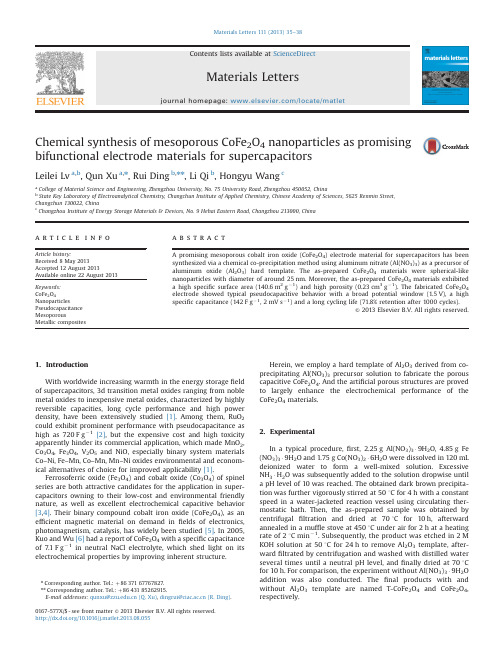
目录Part 1 PID type fuzzy controller and parameters adaptive method (1)Part 2 Application of self adaptation fuzzy-PID control for main steam temperature control system in power station (7)Part 3 Neuro-fuzzy generalized predictive control of boiler steam temperature ..................................................................... (13)Part 4 为Part3译文:锅炉蒸汽温度模糊神经网络的广义预测控制21Part 1 PID type fuzzy controller and Parametersadaptive methodWu zhi QIAO, Masaharu MizumotoAbstract: The authors of this paper try to analyze the dynamic behavior of the product-sum crisp type fuzzy controller, revealing that this type of fuzzy controller behaves approximately like a PD controller that may yield steady-state error for the control system. By relating to the conventional PID control theory, we propose a new fuzzy controller structure, namely PID type fuzzy controller which retains the characteristics similar to the conventional PID controller. In order to improve further the performance of the fuzzy controller, we work out a method to tune the parameters of the PID type fuzzy controller on line, producing a parameter adaptive fuzzy controller. Simulation experiments are made to demonstrate the fine performance of these novel fuzzy controller structures.Keywords: Fuzzy controller; PID control; Adaptive control1. IntroductionAmong various inference methods used in the fuzzy controller found in literatures , the most widely used ones in practice are the Mamdani method proposed by Mamdani and his associates who adopted the Min-max compositional rule of inference based on an interpretation of a control rule as a conjunction of the antecedent and consequent, and the product-sum method proposed by Mizumoto who suggested to introduce the product and arithmetic mean aggregation operators to replace the logical AND (minimum) and OR (maximum) calculations in the Min-max compositional rule of inference.In the algorithm of a fuzzy controller, the fuzzy function calculation is also a complicated and time consuming task. Tagagi and Sugeno proposed a crisp type model in which the consequent parts of the fuzzy control rules are crisp functional representation or crisp real numbers in the simplified case instead of fuzzy sets . With this model of crisp real number output, the fuzzy set of the inference consequence willbe a discrete fuzzy set with a finite number of points, this can greatly simplify the fuzzy function algorithm.Both the Min-max method and the product-sum method are often applied with the crisp output model in a mixed manner. Especially the mixed product-sum crisp model has a fine performance and the simplest algorithm that is very easy to be implemented in hardware system and converted into a fuzzy neural network model. In this paper, we will take account of the product-sum crisp type fuzzy controller.2. PID type fuzzy controller structureAs illustrated in previous sections, the PD function approximately behaves like a parameter time-varying PD controller. Since the mathematical models of most industrial process systems are of type, obviously there would exist an steady-state error if they are controlled by this kind of fuzzy controller. This characteristic has been stated in the brief review of the PID controller in the previous section.If we want to eliminate the steady-state error of the control system, we can imagine to substitute the input (the change rate of error or the derivative of error) of the fuzzy controller with the integration of error. This will result the fuzzy controller behaving like a parameter time-varying PI controller, thus the steady-state error is expelled by the integration action. However, a PI type fuzzy controller will have a slow rise time if the P parameters are chosen small, and have a large overshoot if the P or I parameters are chosen large. So there may be the time when one wants to introduce not only the integration control but the derivative control to the fuzzy control system, because the derivative control can reduce the overshoot of the system's response so as to improve the control performance. Of course this can be realized by designing a fuzzy controller with three inputs, error, the change rate of error and the integration of error. However, these methods will be hard to implement in practice because of the difficulty in constructing fuzzy control rules. Usually fuzzy control rules are constructed by summarizing the manual control experience of an operator who has been controlling the industrial process skillfully and successfully. The operator intuitively regulates the executor to control the process by watching theerror and the change rate of the error between the system's output and the set-point value. It is not the practice for the operator to observe the integration of error. Moreover, adding one input variable will greatly increase the number of control rules, the constructing of fuzzy control rules are even more difficult task and it needs more computation efforts. Hence we may want to design a fuzzy controller that possesses the fine characteristics of the PID controller by using only the error and the change rate of error as its inputs.One way is to have an integrator serially connected to the output of the fuzzy controller as shown in Fig. 1. In Fig. 1,1K and 2K are scaling factors for e and ~ respectively, and fl is the integral constant. In the proceeding text, for convenience, we did not consider the scaling factors. Here in Fig. 2, when we look at the neighborhood of NODE point in the e - ~ plane, it follows from (1) that the control input to the plant can be approximated by(1)Hence the fuzzy controller becomes a parameter time-varying PI controller, itsequivalent proportional control and integral control components are BK2D and ilK1 P respectively. We call this fuzzy controller as the PI type fuzzy controller (PI fc). We can hope that in a PI type fuzzy control system, the steady-state error becomes zero.To verify the property of the PI type fuzzy controller, we carry out some simulation experiments. Before presenting the simulation, we give a description of the simulation model. In the fuzzy control system shown in Fig. 3, the plant model is a second-order and type system with the following transfer function:)1)(1()(21++=s T s T K s G (2) Where K = 16, 1T = 1, and 2T = 0.5. In our simulation experiments, we use thediscrete simulation method, the results would be slightly different from that of a continuous system, the sampling time of the system is set to be 0.1 s. For the fuzzy controller, the fuzzy subsets of e and d are defined as shown in Fig. 4. Their coresThe fuzzy control rules are represented as Table 1. Fig. 5 demonstrates the simulation result of step response of the fuzzy control system with a Pl fc. We can see that the steady-state error of the control system becomes zero, but when the integration factor fl is small, the system's response is slow, and when it is too large, there is a high overshoot and serious oscillation. Therefore, we may want to introduce the derivative control law into the fuzzy controller to overcome the overshoot and instability. We propose a controller structure that simply connects the PD type and the PI type fuzzy controller together in parallel. We have the equivalent structure of that by connecting a PI device with the basic fuzzy controller serially as shown in Fig.6. Where ~ is the weight on PD type fuzzy controller and fi is that on PI type fuzzy controller, the larger a/fi means more emphasis on the derivative control and less emphasis on the integration control, and vice versa. It follows from (7) that the output of the fuzzy controller is(3)3. The parameter adaptive methodThus the fuzzy controller behaves like a time-varying PID controller, its equivalent proportional control, integral control and derivative control components are respectively. We call this new controller structure a PID type fuzzy controller (PID fc). Figs. 7 and 8 are the simulation results of the system's step response of such control system. The influence of ~ and fl to the system performance is illustrated. When ~ > 0 and/3 = 0, meaning that the fuzzy controller behaves like PD fc, there exist a steady-state error. When ~ = 0 and fl > 0, meaning that the fuzzy controller behaves like a PI fc, the steady-state error of the system is eliminated but there is a large overshoot and serious oscillation.When ~ > 0 and 13 > 0 the fuzzy controller becomes a PID fc, the overshoot is substantially reduced. It is possible to get a comparatively good performance by carefully choosing the value of αandβ.4. ConclusionsWe have studied the input-output behavior of the product-sum crisp type fuzzy controller, revealing that this type of fuzzy controller behaves approximately like a parameter time-varying PD controller. Therefore, the analysis and designing of a fuzzy control system can take advantage of the conventional PID control theory. According to the coventional PID control theory, we have been able to propose some improvement methods for the crisp type fuzzy controller.It has been illustrated that the PD type fuzzy controller yields a steady-state error for the type system, the PI type fuzzy controller can eliminate the steady-state error. We proposed a controller structure, that combines the features of both PD type and PI type fuzzy controller, obtaining a PID type fuzzy controller which allows the control system to have a fast rise and a small overshoot as well as a short settling time.To improve further the performance of the proposed PID type fuzzy controller, the authors designed a parameter adaptive fuzzy controller. The PID type fuzzy controller can be decomposed into the equivalent proportional control, integral control and the derivative control components. The proposed parameter adaptive fuzzy controller decreases the equivalent integral control component of the fuzzy controller gradually with the system response process time, so as to increase the damping of the system when the system is about to settle down, meanwhile keeps the proportional control component unchanged so as to guarantee quick reaction against the system's error. With the parameter adaptive fuzzy controller, the oscillation of the system is strongly restrained and the settling time is shortened considerably.We have presented the simulation results to demonstrate the fine performance of the proposed PID type fuzzy controller and the parameter adaptive fuzzy controller structure.Part 2 Application of self adaptation fuzzy-PID control for main steam temperature control system inpower stationZHI-BIN LIAbstract: In light of the large delay, strong inertia, and uncertainty characteristics of main steam temperature process, a self adaptation fuzzy-PID serial control system is presented, which not only contains the anti-disturbance performance of serial control, but also combines the good dynamic performance of fuzzy control. The simulation results show that this control system has more quickly response, better precision and stronger anti-disturbance ability.Keywords:Main steam temperature;Self adaptation;Fuzzy control;Serial control1. IntroductionThe boiler superheaters of modem thermal power station run under the condition of high temperature and high pressure, and the superheater’s temperature is highest in the steam channels.so it has important effect to the running of the whole thermal power station.If the temperature is too high, it will be probably burnt out. If the temperature is too low ,the efficiency will be reduced So the main steam temperature mast be strictly controlled near the given value.Fig l shows the boiler main steam temperature system structure.Fig.1 boiler main steam temperature systemIt can be concluded from Fig l that a good main steam temperature controlsystem not only has adequately quickly response to flue disturbance and load fluctuation, but also has strong control ability to desuperheating water disturbance. The general control scheme is serial PID control or double loop control system with derivative. But when the work condition and external disturbance change large, the performance will become instable. This paper presents a self adaptation fuzzy-PID serial control system. which not only contains the anti-disturbance performance of serial control, but also combines the good dynamic character and quickly response of fuzzy control .1. Design of Control SystemThe general regulation adopts serial PID control system with load feed forward .which assures that the main steam temperature is near the given value 540℃in most condition .If parameter of PID control changeless and the work condition and external disturbance change large, the performance will become in stable .The fuzzy control is fit for controlling non-linear and uncertain process. The general fuzzy controller takes error E and error change ratio EC as input variables .actually it is a non-linear PD controller, so it has the good dynamic performance .But the steady error is still in existence. In linear system theory, integral can eliminate the steady error. So if fuzzy control is combined with PI control, not only contains the anti-disturbance performance of serial control, but also has the good dynamic performance and quickly response.In order to improve fuzzy control self adaptation ability, Prof .Long Sheng-Zhao and Wang Pei-zhuang take the located in bringing forward a new idea which can modify the control regulation online .This regulation is:]1,0[,)1(∈-+=αααEC E UThis control regulation depends on only one parameter α.Once αis fixed .the weight of E and EC will be fixed and the self adaptation ability will be very small .It was improved by Prof. Li Dong-hui and the new regulation is as follow;]1,0[,,,3,)1(2,)1(1,)1(0,)1({321033221100∈±=-+±=-+±=-+=-+=ααααααααααααE EC E E EC E E EC E E EC E UBecause it is very difficult to find a self of optimum parameter, a new method is presented by Prof .Zhou Xian-Lan, the regulation is as follow:)0(),ex p(12>--=k ke αBut this algorithm still can not eliminate the steady error .This paper combines this algorithm with PI control ,the performance is improved .2. Simulation of Control System3.1 Dynamic character of controlled objectPapers should be limited to 6 pages Papers longer than 6 pages will be subject to extra fees based on their length .Fig .2 main steam temperature control system structureFig 2 shows the main steam temperature control system structure ,)(),(21s W s W δδare main controller and auxiliary controller,)(),(21s W s W o o are characters of the leading and inertia sections,)(),(21s W s W H H are measure unit.3.2 Simulation of the general serial PID control systemThe simulation of the general serial PID control system is operated by MATLAB, the simulation modal is as Fig.3.Setp1 and Setp2 are the given value disturbance and superheating water disturb & rice .PID Controller1 and PID Controller2 are main controller and auxiliary controller .The parameter value which comes from references is as follow :667.37,074.0,33.31)(25)(111111122===++===D I p D I p p k k k s k sk k s W k s W δδFig.3. the general PID control system simulation modal3.3 Simulation of self adaptation fuzzy-PID control system SpacingThe simulation modal is as Fig 4.Auxiliary controller is:25)(22==p k s W δ.Main controller is Fuzzy-PI structure, and the PI controller is:074.0,33.31)(11111==+=I p I p k k s k k s W δFuzzy controller is realized by S-function, and the code is as fig.5.Fig.4. the fuzzy PID control system simulation modalFig 5 the S-function code of fuzzy control3.4 Comparison of the simulationGiven the same given value disturbance and the superheating water disturbance,we compare the response of fuzzy-PID control system with PID serial control system. The simulation results are as fig.6-7.From Fig6-7,we can conclude that the self adaptation fuzzy-PID control system has the more quickly response, smaller excess and stronger anti-disturbance.4. Conclusion(1)Because it combines the advantage of PID controller and fuzzy controller, theself adaptation fuzzy-PID control system has better performance than the general PID serial control system.(2)The parameter can self adjust according to the error E value. so this kind of controller can harmonize quickly response with system stability.Part 3 Neuro-fuzzy generalized predictive controlof boiler steam temperatureXiangjie LIU, Jizhen LIU, Ping GUANAbstract: Power plants are nonlinear and uncertain complex systems. Reliable control of superheated steam temperature is necessary to ensure high efficiency and high load-following capability in the operation of modern power plant. A nonlinear generalized predictive controller based on neuro-fuzzy network (NFGPC) is proposed in this paper. The proposed nonlinear controller is applied to control the superheated steam temperature of a 200MW power plant. From the experiments on the plant and the simulation of the plant, much better performance than the traditional controller is obtained.Keywords: Neuro-fuzzy networks; Generalized predictive control; Superheated steam temperature1. IntroductionContinuous process in power plant and power station are complex systems characterized by nonlinearity, uncertainty and load disturbance. The superheater is an important part of the steam generation process in the boiler-turbine system, where steam is superheated before entering the turbine that drives the generator. Controlling superheated steam temperature is not only technically challenging, but also economically important.From Fig.1,the steam generated from the boiler drum passes through the low-temperature superheater before it enters the radiant-type platen superheater. Water is sprayed onto the steam to control the superheated steam temperature in both the low and high temperature superheaters. Proper control of the superheated steam temperature is extremely important to ensure the overall efficiency and safety of the power plant. It is undesirable that the steam temperature is too high, as it can damage the superheater and the high pressure turbine, or too low, as it will lower the efficiency of the power plant. It is also important to reduce the temperaturefluctuations inside the superheater, as it helps to minimize mechanical stress that causes micro-cracks in the unit, in order to prolong the life of the unit and to reduce maintenance costs. As the GPC is derived by minimizing these fluctuations, it is amongst the controllers that are most suitable for achieving this goal.The multivariable multi-step adaptive regulator has been applied to control the superheated steam temperature in a 150 t/h boiler, and generalized predictive control was proposed to control the steam temperature. A nonlinear long-range predictive controller based on neural networks is developed into control the main steam temperature and pressure, and the reheated steam temperature at several operating levels. The control of the main steam pressure and temperature based on a nonlinear model that consists of nonlinear static constants and linear dynamics is presented in that.Fig.1 The boiler and superheater steam generation process Fuzzy logic is capable of incorporating human experiences via the fuzzy rules. Nevertheless, the design of fuzzy logic controllers is somehow time consuming, as the fuzzy rules are often obtained by trials and errors. In contrast, neural networks not only have the ability to approximate non-linear functions with arbitrary accuracy, they can also be trained from experimental data. The neuro-fuzzy networks developed recently have the advantages of model transparency of fuzzy logic and learning capability of neural networks. The NFN is have been used to develop self-tuning control, and is therefore a useful tool for developing nonlinear predictive control. Since NFN is can be considered as a network that consists of several local re-gions, each of which contains a local linear model, nonlinear predictive control based onNFN can be devised with the network incorporating all the local generalized predictive controllers (GPC) designed using the respective local linear models. Following this approach, the nonlinear generalized predictive controllers based on the NFN, or simply, the neuro-fuzzy generalized predictive controllers (NFG-PCs)are derived here. The proposed controller is then applied to control the superheated steam temperature of the 200MW power unit. Experimental data obtained from the plant are used to train the NFN model, and from which local GPC that form part of the NFGPC is then designed. The proposed controller is tested first on the simulation of the process, before applying it to control the power plant.2. Neuro-fuzzy network modellingConsider the following general single-input single-output nonlinear dynamic system:),1(),...,(),(),...,1([)(''+-----=uy n d t u d t u n t y t y f t y ∆+--/)()](),...,1('t e n t e t e e (1)where f[.]is a smooth nonlinear function such that a Taylor series expansion exists, e(t)is a zero mean white noise and Δis the differencing operator,''',,e u y n n n and d are respectively the known orders and time delay of the system. Let the local linear model of the nonlinear system (1) at the operating point )(t o be given by the following Controlled Auto-Regressive Integrated Moving Average (CARIMA) model:)()()()()()(111t e z C t u z B z t y z A d ----+∆= (2) Where )()(),()(1111----∆=z andC z B z A z A are polynomials in 1-z , the backward shift operator. Note that the coefficients of these polynomials are a function of the operating point )(t o .The nonlinear system (1) is partitioned into several operating regions, such that each region can be approximated by a local linear model. Since NFN is a class of associative memory networks with knowledge stored locally, they can be applied to model this class of nonlinear systems. A schematic diagram of the NFN is shown in Fig.2.B-spline functions are used as the membership functions in theNFN for the following reasons. First, B-spline functions can be readily specified by the order of the basis function and the number of inner knots. Second, they are defined on a bounded support, and the output of the basis function is always positive, i.e.,],[,0)(j k j j k x x λλμ-∉=and ],[,0)(j k j j k x x λλμ-∈>.Third, the basis functions form a partition of unity, i.e.,.][,1)(min,∑∈≡j mam j k x x x x μ(3)And fourth, the output of the basis functions can be obtained by a recurrence equation.Fig. 2 neuro-fuzzy network The membership functions of the fuzzy variables derived from the fuzzy rules can be obtained by the tensor product of the univariate basis functions. As an example, consider the NFN shown in Fig.2, which consists of the following fuzzy rules: IF operating condition i (1x is positive small, ... , and n x is negative large),THEN the output is given by the local CARIMA model i:...)()(ˆ...)1(ˆ)(ˆ01+-∆+-++-=d t u b n t y a t y a t yi i a i in i i i a )(...)()(c i in i b i in n t e c t e n d t u b c b -+++--∆+ (4)or )()()()()(ˆ)(111t e z C t u z B z t yz A i i i i d i i ----+∆= (5) Where )()(),(111---z andC z B z A i i i are polynomials in the backward shift operator 1-z , and d is the dead time of the plant,)(t u i is the control, and )(t e i is a zero mean independent random variable with a variance of 2δ. The multivariate basis function )(k i x a is obtained by the tensor products of the univariate basis functions,p i x A a nk k i k i ,...,2,1,)(1==∏=μ (6)where n is the dimension of the input vector x , and p , the total number of weights in the NFN, is given by,∏=+=nk i i k R p 1)( (7)Where i k and i R are the order of the basis function and the number of inner knots respectively. The properties of the univariate B-spline basis functions described previously also apply to the multivariate basis function, which is defined on the hyper-rectangles. The output of the NFN is,∑∑∑=====p i i i p i ip i i i a y aa yy 111ˆˆˆ (8) 3. Neuro-fuzzy modelling and predictive control of superheatedsteam temperatureLet θbe the superheated steam temperature, and θμ, the flow of spray water to the high temperature superheater. The response of θcan be approximated by a second order model:The linear models, however, only a local model for the selected operating point. Since load is the unique antecedent variable, it is used to select the division between the local regions in the NFN. Based on this approach, the load is divided into five regions as shown in Fig.3,using also the experience of the operators, who regard a load of 200MW as high,180MW as medium high,160MW as medium,140MW as medium low and 120MW as low. For a sampling interval of 30s , the estimated linear local models )(1-z A used in the NFN are shown in Table 1.Fig. 3 Membership function for local modelsTable 1 Local CARIMA models in neuro-fuzzy modelCascade control scheme is widely used to control the superheated steam temperature. Feed forward control, with the steam flow and the gas temperature as inputs, can be applied to provide a faster response to large variations in these two variables. In practice, the feed forward paths are activated only when there are significant changes in these variables. The control scheme also prevents the faster dynamics of the plant, i.e., the spray water valve and the water/steam mixing, from affecting the slower dynamics of the plant, i.e., the high temperature superheater. With the global nonlinear NFN model in Table 1, the proposed NFGPC scheme is shown in Fig.4.Fig. 4 NFGPC control of superheated steam temperature with feed-for-ward control.As a further illustration, the power plant is simulated using the NFN model given in Table 1,and is controlled respectively by the NFGPC, the conventional linear GPC controller, and the cascaded PI controller while the load changes from 160MW to 200MW.The conventional linear GPC controller is the local controller designed for the“medium”operating region. The results are shown in Fig.5,showing that, as expected, the best performance is obtained from the NFGPC as it is designed based on a more accurate process model. This is followed by the conventional linear GPC controller. The performance of the conventional cascade PI controller is the worst, indicating that it is unable to control satisfactory the superheated steam temperature under large load changes. This may be the reason for controlling the power plant manually when there are large load changes.Fig.5 comparison of the NFGPC, conventional linear GPC, and cascade PI controller.4. ConclusionsThe modeling and control of a 200 MW power plant using the neuro-fuzzy approach is presented in this paper. The NFN consists of five local CARIMA models.The out-put of the network is the interpolation of the local models using memberships given by the B-spline basis functions. The proposed NFGPC is similarly constructed, which is designed from the CARIMA models in the NFN. The NFGPC is most suitable for processes with smooth nonlinearity, such that its full operating range can be partitioned into several local linear operating regions. The proposed NFGPC therefore provides a useful alternative for controlling this class of nonlinear power plants, which are formerly difficult to be controlled using traditional methods.Part 4 为Part3译文:锅炉蒸汽温度模糊神经网络的广义预测控制Xiangjie LIU, Jizhen LIU, Ping GUAN摘要:发电厂是非线性和不确定性的复杂系统。
Adaptive Trajectory Tracking Control of Skid-Steered Mobile Robots
1-4244-0602-1/07/$20.00 ©2007 IEEE.
2605
Authorized licensed use limited to: NANKAI UNIVERSITY. Downloaded on March 2, 2009 at 02:33 from IEEE Xplore. Restrictions apply.
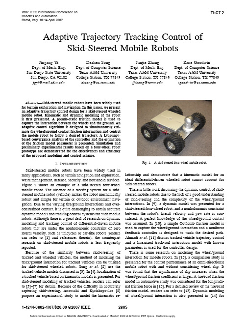
I. I NTRODUCTION Skid-steered mobile robots have been widely used in many applications, such as terrain navigation and exploration, waste management, defense, security, and household services. Figure 1 shows an example of a skid-steered four-wheel mobile robot. The absence of a steering system for a skidsteered mobile robot (vehicle) makes the robot mechanically robust and simple for terrain or outdoor environment navigation. Due to the varying tire/ground interactions and overconstrained contact, it is quite challenging to obtain accurate dynamic models and tracking control systems for such mobile robots. Although there is a great deal of research on dynamic modeling and tracking control of differential-driven mobile robots that are under the nonholonomic constraint of zero lateral velocity, such as unicycles or car-like robots (readers can refer to [1] and references therein), the counterpart research on skid-steered mobile robots is less frequently reported. Because of the similarity between skid-steering of tracked and wheeled vehicles, the method of modeling the track/ground interaction for tracked vehicles can be utilized for skid-steered wheeled robots. Song et al. [2] use the tracked vehicle models discussed in [3]. In [4], localization of a tracked vehicle based on kinematic models is presented. For skid-steered modeling of tracked vehicles, readers can refer to [5]–[7] for details. Because of the difficulty in accurately capturing skid-steering, Anousaki and Kyriakopoulos [8] propose an experimental study to model the kinematic re-
一类不确定Lur'e奇异系统的可靠鲁棒H∞跟踪控制

ACTA AUTOMATICA SINICA
August, 2008
Reliable Robust H ∞ Tracking Control for a Class of Uncertain Lur e Singular Systems
WANG Hui-Jiao1, 2 LIN Yue-Song2 XUE An-Ke2 PAN Hai-Peng1 LU Ren-Quan2
Control of singular systems has been extensively studied in the past years due to the fact that singular systems can better describe physical systems than regular ones. A great number of results based on the theory of regular systems have been extended to the area of singular systems, such as robust stability and robust stabilization problem[1−3] , robust H∞ control problem[4−6] , robust H∞ filtering problem[7] , guarantee cost problem[8] , etc. However, all the aforementioned results are under a full reliability assumption that all control components of the system are in good working condition. As is well known, failures of actuators or sensors, in practical engineering systems, often occur, which may lead to intolerable performance of the closed-loop system. Therefore, from a safety as well as performance point of view, it is required to design a reliable controller which can tolerate actuator or sensor failures and guarantee the stability and performance of resultant closed-loop system. Furthermore, there are lots of results about reliable control for regular systems[9−12] . For singular systems, [13] studied the reliable H∞ control problem with actuator failures and multiple time delays, but the reliable controller design method is based on a basic assumption that control component failures are modeled as outages, that is, when a failure occurs, the signal (in the case of sensors) or the control action (in the case of actuators) simply becomes zero. The outage model is the simplest case of control component failures. In this paper, a more practical and general failure model is adopted for sensor and actuator failures, which consists of a scaling factor with upper and lower bounds to the signal to be measured or to the control action, plus a disturbance. This model was introduced by [14]. For actuators, this general failure model could represent faults in the driving circuitry before the final control actuator. For sensors, it could represent faults in the signal conditioning circuitry at the sensors. To our knowledge, the reliable control problem of singular systems based on such failure model has not yet been fully investigated. On the other hand, designing a controller which can guarantee the output of controlled system tracking the reference signal is of theoretical and practical meaning. There are some results presented on the problem of reliable trackReceived June 29, 2007; in revised form February 23, 2008 Supported by National Natural Science Foundation of China (60434020, 60604003) 1. Institute of Automation, College of Mechanical Engineering and Automation, Zhejiang Sci-Tech University, Hangzhou 310018, P. R. China 2. Institute of Information and Control, Hangzhou Dianzi University, Hangzhou 310018, P. R. China DOI: 10.3724/SP.J.1004.2008.00893
基于自抗扰与观测器的环形耦合多电机协调滑模控制
微电机MIROMOTORS第54卷第4期2021年 4月Vol. 54. No. 4Ape2021基于自抗扰的环形耦合多电机协调滑模控制贺志浩,于海生(青岛大学自动化学院,青岛266071)摘要:在多电机控制系统中,参数摄动和负载转矩变化会影响系统的跟踪精度和同步性能,且传统的补偿方法难以有效的 系统的同步误差。
针对以 ,采用电流 的 耦合结构,设置同步比例系数实 电机的协调运行,设计自抗对电机进行电流 同步误差,同时将非奇异快速终 模和扰动 用于单台电机的控制。
结果表明,所设计的控使系统的鲁棒性和精 有所提高;相比于固定增和PI 补偿,系统的同步误 ,抗 能力强,实 了高精度的多电机协调控制。
关键词:多电机协调控制; 耦合;自抗 ;非异快速终模;扰动观测器中图分类号:TM351; TP273文献标志码:A文章编号:1001-6848(2021)04-0048-08Coordinated Sliding Mode Control of Ring-coupled Multi-motorBased on Activd Disterdance Rejection and ObserverHE Zhihao ,YU Haisheng(Collegc of Automation,,Qingdao University ,Qingdao Shandong 266071,China )Abstract : In multi-motoi controt system ,the parameterr perturbation and load torque change could afect the tracking accuracy and synchronization performance of the system ,and the traditional compensation methods were diKicult to effectively suppress the synchronization erroi of the system. Aiming at the above problems , the ring coupling structure of cuirent compensation was adopted ,the synchronization ratio coefVcients weresel to realiae the coordinated operation of multiple motors ,the active dKturbanca rejection compensatoi wasdesigned to compensate the motoi current to reduce the synchronization erroi, and the non-singulai fast tei- minal sliding mode and disturbance observer were used foi the controt of a single motoi. The simulation re sults show that the designed controt strateay improves the /bustnas and tracking accuracy of the system ;Compared to the fixed gain compensation and PI compensation ,the system has small synchronization erro/,strong anti -interference abfity ,and realizes high-precision munUmotoi coordinated control.Key words : multi-motoi coordinated controt ; ring coupling ; active disturbance rejection compensation ; non-singulai fast terminal sliding mode ; disturbance obse/eio 引言着自动化程度的不断提高,多电机控制系统已被 用到各种领域中, 、 、 、流水线 、机 控 (17。
永磁同步电机鲁棒预测电流控制器设计
第55卷第2期2021年2月电力电子技术Power ElectronicsVol.55,No.2February2021永磁同步电机鲁棒预测电流控制器设计林茂李颖晖1,徐浩军1,查翔2(1.空军工程大学,陕西西安710038; 2.93802部队,陕西西安712200)摘要:预测控制器充分考虑了电力电子器件的非线性离散特性在有限范围内控制开关元器件工作,近年来成为应用到功率变换器和传动装置的热门控制方案。
预测控制器主要基于系统的数学模型进行预测,因此算法对系统参数精度要求较高,然而,实际交流传动系统中存在电感、电容等元器件参数随着系统的运行条件变化(如温度、磁路的饱和等因素)而发生改变,容易对算法造成负面影响。
此处考虑在许多模型参数存在不确定因素时,设计一种改进预测控制算法,对电流误差项进行补偿设计,降低参数不确定性对算法的影响,最后通过仿真实验对该控制方案的可行性进行验证。
关键词:永磁同步电机;预测控制;电流误差项中图分类号:TM351文献标识码:A文章编号:1000-100X(2021)02-0060-05Research on Robust Predictive Current Controller forPermanent Magnet Synchronous MotorsLIN Mao L2,LI Ying-hui1,XU Hao-Jun1,ZHA Xiang2(l.Air Force Engineering University,Xi*an710038,China)Abstract:In recent years,predictive controller becomes a hot control strategy appling to the power converter and transmission scheme,for it fully considering the nonlinear discrete characteristics of the power electronic devices and limited switch components within the scope of operation, predictive controller control method is mainly based on the mathematical model to control system,so the requirements of algorithm to the system parameters accuracy is higher. However,during the actual AC drive system, the parameters of the elements such as inductor, capacitor,resistance,as the system operating condition changes(such as temperature,magnetic circuit saturation,etc.)and change,it easy to lead a negative impact to the predictive controller algorithm.When model parameters are uncertain,an improved predictive control algorithm is designed to compensate current error term and reduce the influence of parameter uncertainty on the algorithm.Finally,the feasibility of the control scheme is verified through simulation experiment. Keywords:permanent magnet synchronous motors;predictive control;current error term1引言永磁同步电机(PMSM)调速系统中存在干扰及不确定因素,如随温度非线性变化的磁链、定子电阻和电感参数"等均会引起电机转矩脉动干扰和转动惯量变化。
基于自校正自抗扰控制的多电机协同系统
No.2Feb.2021第2期2021年2月组合机床与自动化加工技术Modular Machine Tool & Automatic Manufadtring Techninur文章编号:1001 -2265(2021)02 -0077 -05DOI : 10.13462/j. cnki mmtamt. 2021.02. 019基于自校正自抗扰控制的多电机协同系统汪昕杨,刘亚超,钟永彬,高健(广东工业大学机电工程学院,广州510006)摘要:针对多电机协同控制系统的同步控制精度问题,提出一种自校正速度补偿器与改进型自抗扰 控制器结合的新型控制策略。
该方法通过自校正速度补偿器对多轴电机反馈的速度量进行校正补偿,与系统误差一起输入到改进型自抗扰控制器中实现精确控制,以解决多电机协同控制系统在实际应用中存在的滞后性、抗干扰能力弱等问题。
通过仿真验证所提方法对系统跟踪精度和抗干扰 能力的有效性,仿真结果表明,在高频噪声影响下,该方法能够大幅提升系统的响应速度和抗干扰能力,有效实现多电机的精密协同控制。
关键词:协同控制;自校正;控制性能;高频噪声中图分类号:TH16;TG65文献标识码:AMulti-motor Coordinateb System Based on Self-sorrection Active Disttrdancc Rejection ControlWANG Xin-yang , LID Ya-chao , ZHONG Yong-bin , GAO Jian(Colleae of Mechanicai and Electricai Engineering , Guangdong University of Technoloyy , Guangzhou 510006, China )Abstract : Focusing on the proMem of synchronous conaol accuracy of multi-motor coordinated conhoi syshem , anew conheo2sheahegy combining sef-co e echion speed compensahoeand impeoved achivedishueb-ance t V —tion conWoller is proposed. The method correcti and compensates the speed of the multi-axis mo- hoefeedback feom hhe elf-co e echion peed compen ahoe , and inpuhihinho hheimpeoved achivedihuebanceV —tion contoHeT together with system error to realize precise contoi and solve the problems of hysteresis and weak anti-interference ability in the practical application of multi-motor coordinated conhoi system.The simulation vsu U s show that under the influence of high frequency noise , this method can greatly im prove the response speed and anh-interference ability of the system, and effec t ively realize the pvcise co ordinated conhoi of multi-motor.Key wors : coordinated coniol ; self- correction ; coniol performance ; high frequency noise0引言多电机协同控制系统在机器人、高精度加工平台 等现代化工业领域中具有极高的研究价值,在实际应 用中协同控制性能的好坏将直接影响其加工产品的优 良程度⑴。
ADAPTIVE-ROBUST CONTROL OF THE STEWART-GOUGH PLATFORM AS A SIX DOF PARALLEL ROBOT
Keywords: Parallel robots, Stewart-Gough platform, adaptive-robust control scheme, Lagrangian dynamics.
1. INTRODUCTION
Parallel manipulators such as a Stewart-Gough platform, [1], have some advantages such as high force-to-weight ratio (high rigidity), compact size, capability for control with a very high bandwidth, their robustness against external forces and error accumulation, high dexterity and are suitable for an accurate positioning system. These manipulators have found a variety of applications in flight and vehicle simulators, high precision machining centers, mining machines, medical instruments, spatial devices, etc. However, they have some drawbacks of relatively small workspace and difficult forward kinematics problem. Generally, because of the nonlinearity and the complexity of the equations, forward kinematics of parallel manipulators is very complicated and difficult to solve. This is a contrast to serial manipulators. There are analytic solutions [2, 3 and 4], numerical ones [5] and solutions using the observers [6] for the forward kinematics problem of parallel robots. The analytical methods provide the exact solution; but, they are too complicated because the solution is obtained by solving the high-order polynomial equations. There is also the selection problem of the exact solution among the several ones. In fact there exists no general closed-form solution for the above problem. The Newton-Raphson method is known as a simple algorithm for solving nonlinear equations, whose convergence is good, but it takes much calculation time, and also it sometimes converges to the wrong solution according to the initial values. This method was used to solve the forward kinematic problem of platform-type robotic manipulators [5]. In the methods using the observers [6], two kinds of observers, linear and nonlinear, have been used. The linear observer is based on linearizing the nonlinear terms and leaves the steady-state error. The nonlinear observer has the difficulty to select the observation gains. A neural network based method may be applied to solve the forward kinematics problem as a basic element in the modeling and control of the parallel robots [7]. While the kinematics of parallel manipulators has been studied extensively during the last two decades, fewer contributions can be found on the dynamics problem of parallel mainpulators. Dynamical analysis of parallel robots, which is very important to develop a model-based controller, is complicated because of the existence of multiple closed-loop chains [8, 9]. Dynamic equations of a Stewart-Gough platform can be derived based on Lagrange' s formulation [10].
分数阶多机器人的领航-跟随型环形编队控制
第38卷第1期2021年1月控制理论与应用Control Theory&ApplicationsV ol.38No.1Jan.2021分数阶多机器人的领航–跟随型环形编队控制伍锡如†,邢梦媛(桂林电子科技大学电子工程与自动化学院,广西桂林541004)摘要:针对多机器人系统的环形编队控制复杂问题,提出一种基于分数阶多机器人的环形编队控制方法,应用领航–跟随编队方法来控制多机器人系统的环形编队和目标包围,通过设计状态估测器,实现对多机器人的状态估计.由领航者获取系统中目标状态的信息,跟随者监测到领航者的状态信息并完成包围环绕编队控制,使多机器人系统形成对动态目标的目标跟踪.根据李雅普诺夫稳定性理论和米塔格定理,得到多机器人系统环形编队控制的充分条件,实现对多机器人系统对目标物的包围控制,通过对一组多机器人队列的目标包围仿真,验证了该方法的有效性.关键词:分数阶;多机器人;编队控制;环形编队;目标跟踪引用格式:伍锡如,邢梦媛.分数阶多机器人的领航–跟随型环形编队控制.控制理论与应用,2021,38(1):103–109DOI:10.7641/CTA.2020.90969Annular formation control of the leader-follower multi-robotbased on fractional orderWU Xi-ru†,XING Meng-yuan(School of Electronic Engineering and Automation,Guilin University of Electronic Technology,Guilin Guangxi541004,China) Abstract:Aiming at the complex problem of annular formation control for fractional order multi robot system,an an-nular formation control method based on fractional order multi robot is proposed.The leader follower formation method is used to control the annular formation and target envelopment of the multi robot systems.The state estimation of multi robot is realized by designing state estimator.The leader obtains the information of the target state in the system,the followers detects the status of the leader and complete annular formation control,the multi-robot system forms the target tracking of the dynamic target.According to Lyapunov stability theory and Mittag Leffler’s theorem,the sufficient conditions of the annular formation control for the multi robot systems are obtained in order to achieve annular formation control of the leader follower multi robot.The effectiveness of the proposed method is verified by simulation by simulation of a group of multi robot experiments.Key words:fractional order;multi-robots;formation control;annular formation;target trackingCitation:WU Xiru,XING Mengyuan.Annular formation control of the leader-follower multi-robot based on fractional order.Control Theory&Applications,2021,38(1):103–1091引言近年来,随着机器人技术的崛起和发展,各式各样的机器人技术成为了各个领域不可或缺的一部分,推动着社会的发展和进步.与此同时,机器人面临的任务也更加复杂,单个机器人已经无法独立完成应尽的责任,这就使得多机器人之间相互协作、共同完成同一个给定任务成为当前社会的研究热点.多机器人系统控制的研究主要集中在一致性问题[1]、多机器人编队控制问题[2–3]、蜂拥问题[4–5]等.其中,编队控制问题作为多机器人系统的主要研究方向之一,是国内外研究学者关注的热点问题.编队控制在生活生产、餐饮服务尤其是军事作战等领域都发挥着极大的作用.例如水下航行器在水中的自主航行和编队控制、军事作战机对空中飞行器的打击以及无人机在各行业的应用等都是多机器人编队控制上的用途[6–7].目前,多机器人编队控制方法主要有3种,其中在多机器收稿日期:2019−11−25;录用日期:2020−08−10.†通信作者.E-mail:****************;Tel.:+86132****1790.本文责任编委:黄攀峰.国家自然科学基金项目(61603107,61863007),桂林电子科技大学研究生教育创新计划项目(C99YJM00BX13)资助.Supported by the National Natural Science Foundation of China(61603107,61863007)and the Innovation Project of GUET Graduate Education (C99YJM00BX13).104控制理论与应用第38卷人系统编队控制问题上应用最广泛的是领航–跟随法[8–10];除此之外,还有基于行为法和虚拟结构法[11].基于行为的多机器人编队方法在描述系统整体时不够准确高效,且不能保证系统控制的稳定性;而虚拟结构法则存在系统灵活性不足的缺陷.领航–跟随型编队控制法具有数学分析简单、易保持队形、通信压力小等优点,被广泛应用于多机器人系统编队[12].例如,2017年,Hu等人采用分布式事件触发策略,提出一种新的自触发算法,实现了线性多机器人系统的一致性[13];Zuo等人利用李雅普诺夫函数,构造具有可变结构的全局非线性一致控制律,研究多机器人系统的鲁棒有限时间一致问题[14].考虑到分数微积分的存储特性,开发分数阶一致性控制的潜在应用具有重要意义.时中等人于2016年设计了空间遥操作分数阶PID 控制系统,提高了机器人系统的跟踪性能、抗干扰性、鲁棒性和抗时延抖动性能[15].2019年,Z Yang等人探讨了分数阶多机器人系统的领航跟随一致性问题[16].而在多机器人的环形编队控制中,对具有分数阶动力学特性的多机器人系统的研究极其有限,大部分集中在整数阶的阶段.而采用分数阶对多机器人系统目标包围编队控制进行研究,综合考虑了非局部分布式的影响,更好地描述具有遗传性质的动力学模型.使得系统的模型能更准确的反映系统的性态,对多机器人编队控制的研究非常有利.目标包围控制问题是编队控制的一个分支,是多智能体编队问题的重点研究领域.随着信息技术的高速发展,很多专家学者对多机器人系统的目标包围控制问题进行了研究探讨.例如,Kim和Sugie于2017年基于一种循环追踪策略设计分布式反馈控制律,保证了多机器人系统围绕一个目标机器人运动[17].在此基础上,Lan和Yan进行了拓展,研究了智能体包围多个目标智能体的问题,并把这个问题分为两个步骤[18]. Kowdiki K H和Barai K等人则研究了单个移动机器人对任意时变曲线的跟踪包围问题[19].Asif M考虑了机器人与目标之间的避障问题,提出了两种包围追踪控制算法;并实现了移动机器人对目标机器人的包围追踪[20].鉴于以上原因,本文采用了领航–跟随型编队控制方法来控制多机器人系统的环形编队和目标包围,通过设计状态估测器,实现对多机器人的状态估计.系统中目标状态信息只能由领航者获取,确保整个多机器人系统编队按照预期的理想编队队形进行无碰撞运动,并最终到达目标位置,对目标、领航者和跟随者的位置分析如图1(a)所示,图1(b)为编队控制后的状态.通过应用李雅普诺夫稳定性理论,得到实现多机器人系统环形编队控制的充分条件.最后通过对一组多机器人队列进行目标包围仿真,验证了该方法的有效性.(a)编队控制前(b)编队控制后图1目标、领航者和追随者的位置分析Fig.1Location analysis of targets,pilots and followers2代数图论与分数阶基础假定一个含有N个智能体的系统,通讯网络拓扑图用G={v,ε}表示,定义ε=v×v为跟随者节点之间边的集合,v={v i,i=1,2,···,N}为跟随者节点的集合.若(v i,v j)∈ε,则v i与v j为相邻节点,定义N j(t)={i|(v i,v j)∈ε,v i∈v}为相邻节点j的标签的集合.那么称第j个节点是第i 个节点的邻居节点,用N j(t)={i|(v i,v j)∈ε,v i∈v}表示第i个节点的邻居节点集合.矩阵L=D−A称为与图G对应的拉普拉斯矩阵.其中:∆是对角矩阵,对角线元素i=∑jN i a ij.若a ij=a ji,i,j∈I,则称G是无向图,否则称为有向图.如果节点v i与v j之间一组有向边(v i,v k1)(v k1,v k2)(v k2,v k3)···(v kl,v j),则称从节点v i到v j存在有向路径.定义1Riemann-Liouville(RL)分数阶微分定义:RLD atf(t)=1Γ(n−a)d nd t ntt0f(τ)(t−τ)a−n+1dτ,(1)其中:t>t0,n−1<α<n,n∈Z+,Γ(·)为伽马函数.定义2Caputo(C)分数阶微分定义:CDαtf(t)=1Γ(n−α)tt0f n(τ)(t−τ)α−n+1dτ,(2)其中:t>t0,n−1<α<n,n∈Z+,Γ(·)为伽马第1期伍锡如等:分数阶多机器人的领航–跟随型环形编队控制105函数.定义3定义具有两个参数α,β的Mittag-Leffler方程为E α,β(z )=∞∑k =1z kΓ(αk +β),(3)其中:α>0,β>0.当β=1时,其单参数形式可表示为E α,1(z )=E α(z )=∞∑k =1z kΓ(αk +1).(4)引理1[21]假定存在连续可导函数x (t )∈R n ,则12C t 0D αt x T (t )x (t )=x T (t )C t 0D αt x (t ),(5)引理2[21]假定x =0是系统C t 0D αt x (t )=f (x )的平衡点,且D ⊂R n 是一个包含原点的域,R 是一个连续可微函数,x 满足以下条件:{a 1∥x ∥a V (t ) a 2∥x ∥ab ,C t 0D αt V (t ) −a 3∥x ∥ab,(6)其中:t 0,x ∈R ,α∈(0,1),a 1,a 2,a 3,a,b 为任意正常数,那么x =0就是Mittag-Leffler 稳定.3系统环形编队控制考虑包含1个领航者和N 个跟随者的分数阶非线性多机器人系统.领航者的动力学方程为C t 0D αt x 0(t )=u 0(t ),(7)式中:0<α<1,x 0(t )∈R 2是领航者的位置状态,u 0(t )∈R 2是领航者的控制输入.跟随者的动力学模型如下:C t 0D αt x i (t )=u i (t ),i ∈I,(8)式中:0<α<1,x i (t )∈R 2是跟随者的位置状态,u i (t )∈R 2是跟随者i 在t 时刻的控制输入,I ={1,2,···,N }.3.1领航者控制器的设计对于领航者,选择如下控制器:u 0(t )=−k 1(x 0(t )−˜x 0(t ))−k 2sgn(x 0(t )−˜x 0(t )),(9)C t 0D αt x 0(t )=u 0(t )=−k 1(x 0(t )−˜x 0(t ))−k 2sgn(x 0(t )−˜x 0(t )).(10)设计一个李雅普诺夫函数:V (t )=12(x 0(t )−˜x 0(t ))T (x 0(t )−˜x 0(t )).(11)根据引理1,得到该李雅普诺夫函数的α阶导数如下:C 0D αt V(t )=12C 0D αt (x 0(t )−˜x 0(t ))T (x 0(t )−˜x 0(t )) (x 0(t )−˜x 0(t ))TC 0D αt (x 0(t )−˜x0(t ))=(x 0(t )−˜x 0(t ))T [C 0D αt x 0(t )−C 0D αt ˜x0(t )]=(x 0(t )−˜x 0(t ))T [−k 1(x 0(t )−˜x 0(t ))−k 2sgn(x 0(t )−˜x 0(t ))−C 0D αt ˜x0(t )]=−k 1(x 0(t )−˜x 0(t ))T (x 0(t )−˜x 0(t ))−k 2∥x 0(t )−˜x 0(t )∥−(x 0(t )−˜x 0(t ))TC 0D αt ˜x0(t )=−2k 1V (t )−k 2∥x 0(t )−˜x 0(t )∥+∥C 0D αt ˜x0(t )∥∥x 0(t )−˜x 0(t )∥=−2k 1V (t )−(k 2−∥C 0D ∝t ˜x0(t )∥)∥x 0(t )−˜x 0(t )∥ −2k 1V (t ).(12)令a 1=a 2=12,a 3=2k 1,ab =2,a >0,b >0,得到a 1∥x 0(t )−˜x 0(t )∥a V (t ) a 2∥x 0(t )−˜x 0(t )∥ab ,(13)C t 0D αt V(t ) −a 3∥x 0(t )−˜x 0(t )∥ab .(14)根据引理2,可知lim t →∞∥x 0(t )−˜x 0(t )∥=0,即x 0(t )逐渐趋近于˜x 0(t ).为了使跟随者能够跟踪观测到领航者的状态,设计了一个状态估测器.令ˆx i ∈R 2是追随者对领航者的状态估计,给出了ˆx i 的动力学方程C 0D αt ˆx i=β(∑j ∈N ia ij g ij (t )+d i g i 0(t )),(15)其中g ij =˜x j (t )−˜x i (t )∥˜x j (t )−˜x i (t )∥,˜x j (t )−˜x i (t )=0,0,˜x j (t )−˜x i (t )=0.(16)对跟随者取以下李雅普诺夫函数:V (t )=12N ∑i =1(ˆx i (t )−x 0(t ))T (ˆx i (t )−x 0(t )).(17)计算该函数的α阶导数如下:C 0D αt V(t )=12C 0D αtN ∑i =1(ˆx i (t )−x 0(t ))T (ˆx i (t )−x 0(t )) N ∑i =1(ˆx i (t )−x 0(t ))TC 0D αt (ˆx i (t )−x 0(t ))=N ∑i =1(ˆx i (t )−x 0(t ))T [C 0D αt ˆxi (t )−C 0D αt x 0(t )]=N ∑i =1(ˆx i (t )−x 0(t ))T [β(∑j ∈N ia ijˆx j (t )−ˆx i (t )∥ˆx j (t )−ˆx i (t )∥+d iˆx 0(t )−ˆx i (t )∥ˆx 0(t )−ˆx i (t )∥)−C 0D αt x 0(t )]=N ∑i =1(ˆx i (t )−x 0(t ))T β(∑j ∈N i a ij ˆx j (t )−ˆx i (t )∥ˆx j (t )−ˆx i(t )∥+106控制理论与应用第38卷d iˆx 0(t )−ˆx i (t )∥ˆx 0(t )−ˆx i (t )∥)−N ∑i =1(ˆx i (t )−x 0(t ))TC 0D αt x 0(t )=βN ∑i =1(ˆx i (t )−x 0(t ))T ∑j ∈N i a ij ˆx j (t )−ˆx i (t )∥ˆx j (t )−ˆx i (t )∥+βN ∑i =1(ˆx i (t )−x 0(t ))Td i ˆx 0(t )−ˆx i (t )∥ˆx 0(t )−ˆx i(t )∥−N ∑i =1(ˆx i (t )−x 0(t ))TC 0D αt x 0(t ).(18)在上式中,令C 0D αt V (t )=N 1+N 2以方便后续计算,其中:N 1=βN ∑i =1(ˆx i (t )−x 0(t ))T ∑j ∈N i a ij ˆx j (t )−ˆx i (t )∥ˆx j (t )−ˆx i (t )∥+βN ∑i =1(ˆx i (t )−x 0(t ))Td i ˆx 0(t )−ˆx i (t )∥ˆx 0(t )−ˆx i (t )∥=β2[N ∑i =1N ∑j =1a ij (ˆx i (t )−x 0(t ))T ˆx j (t )−ˆx i (t )∥ˆx j (t )−ˆx i (t )∥+N ∑j =1N ∑i =1a ij (ˆx j (t )−x 0(t ))Tˆx i (t )−ˆx j (t )∥ˆx i (t )−ˆx j (t )∥]−βN ∑i =1d i∥ˆx 0(t )−ˆx i (t )∥2∥ˆx 0(t )−ˆx i (t )∥=β2N ∑i =1N ∑j =1a ij [(ˆx i (t )−x 0(t ))Tˆx j (t )−ˆx i (t )∥ˆx j (t )−ˆx i (t )∥−(ˆx j (t )−x 0(t ))T ˆx i (t )−ˆx j (t )∥ˆx i (t )−ˆx j (t )∥]−βN ∑i =1d i∥ˆx 0(t )−ˆx i (t )∥2∥ˆx 0(t )−ˆx i (t )∥=β2N ∑i =1N ∑j =1a ij [ˆx T i(t )ˆx j (t )−ˆx i (t )∥ˆx j (t )−ˆx i (t )∥−x T 0(t )ˆx j (t )−ˆx i (t )∥ˆx j (t )−ˆx i (t )∥−ˆx T j(t )ˆx i (t )−ˆx j (t )∥ˆx i (t )−ˆx j (t )∥+x T0(t )ˆx i (t )−ˆx j (t )∥ˆx i (t )−ˆx j (t )∥]−βN ∑i =1d i ∥ˆx 0(t )−ˆx i (t )∥=β2N ∑i =1N ∑j =1a ij [ˆx T i (t )ˆx j (t )−ˆx i (t )∥ˆx j (t )−ˆx i (t )∥−ˆx T j (t )ˆx i (t )−ˆx j (t )∥ˆx i (t )−ˆx j (t )∥]−βN ∑i =1d i ∥ˆx 0(t )−ˆx i (t )∥2∥ˆx 0(t )−ˆx i (t )∥=β2N ∑i =1N ∑j =1a ij (ˆx T i(t )−ˆx Tj (t ))ˆx j (t )−ˆx i (t )∥ˆx j (t )−ˆx i (t )∥−βN ∑i =1d i ∥ˆx 0(t )−ˆx i (t )∥2∥ˆx 0(t )−ˆx i (t )∥=−β(12N ∑i =1N ∑j =1a ij (ˆx T j (t )−ˆx T i (t ))׈x j (t )−ˆx i (t )∥ˆx j (t )−ˆx i (t )∥+N ∑i =1d i ∥ˆx 0(t )−ˆx i (t )∥2∥ˆx 0(t )−ˆx i (t )∥),(19)N 2=−N ∑i =1(ˆx i (t )−x 0(t ))TC 0D αt x 0(t )=N ∑i =1∥ˆx i (t )−x 0(t )∥∥C 0D αt x 0(t )∥×cos {ˆx i (t )−x 0(t ),−C 0D αt x 0(t )}.(20)由于∥C 0D αt x 0(t )∥k 1∥x 0(t )−˜x 0(t )∥+k 2∥sgn(x 0(t )−˜x 0(t ))∥ k 1∥x 0(t )−˜x 0(t )∥+k 2.(21)根据定义3,当lim t →∞∥x 0(t )−˜x 0(t )∥=0时,存在T >0(T 为实数),使得在t >T 时∥x 0(t )−˜x 0(t )∥ ε成立,那么对于t >T ,有0<∥C 0D αt x 0(t )∥ k 1ε+k 2=M 2,可得−N ∑i =1(ˆx i (t )−x 0(t ))TC 0D αt x 0(t )N ∑i =1∥ˆx i (t )−x 0(t )∥M 2M 2N max {∥ˆx i (t )−x 0(t )∥},(22)C 0D αt V(t ) −(β−M 2N )max i ∈I{∥ˆx i (t )−x 0(t )∥}−2β1λmin V (t ).(23)根据引理2,得lim t →∞∥ˆx i (t )−x 0(t )∥=0.(24)由上式可知,ˆx i (t )在对目标的追踪过程中逐渐趋近于x 0(t ).3.2跟随者控制器的设计在本文中,整个多机器人系统中领导者能够直接获得目标的位置信息,将这些信息传递给追随者,因此需要为每个追随者设计观测器来估计目标的状态.令ϕi (t )∈R 2由跟随者对目标i 的状态估计,给出ϕi (t )的动力学方程C 0D αt ϕi(t )=α(∑j ∈N ia ij f ij (t )+d i f i 0(t )),(25)其中f ij =ϕj (t )−ϕi (t )∥ϕj (t )−ϕi (t )∥,ϕj (t )−ϕi (t )=0,0,ϕj (t )−ϕi (t )=0.(26)取如下李雅普诺夫函数:V (t )=12N ∑i =1(ϕi (t )−r (t ))T (ϕi (t )−r (t )).(27)计算α阶导数如下:C 0D αt V(t )=第1期伍锡如等:分数阶多机器人的领航–跟随型环形编队控制10712N ∑i =1(ϕi (t )−r (t ))T (ϕi (t )−r (t )) N ∑i =1(ϕi (t )−r (t ))TC 0D αt (ϕi (t )−r (t ))=N ∑i =1(ϕi (t )−r (t ))T [C 0D αt ϕi (t )−C 0D αt r (t )]=N ∑i =1(φi (t )−r (t ))T [α(∑j ∈N ia ij f ij (t )+d i f i 0(t ))]−C 0D αt r (t )=N ∑i =1(ϕi (t )−r (t ))T α(∑j ∈N ia ij ϕj (t )−ϕi (t )∥ϕj (t )−ϕi (t )∥+d i ϕ(t )−ϕi (t )∥ϕ(t )−ϕi (t )∥)=βN ∑i =1(ϕi (t )−r (t ))T ∑j ∈N i a ijϕj (t )−ϕi (t )∥ϕj (t )−ϕi(t )∥+βN ∑i =1(ϕi (t )−r (t ))T d i ϕ(t )−ϕi (t )∥ϕ(t )−ϕi(t )∥−N ∑i =1(ϕi (t )−r (t ))TC 0D αt r (t ),(28)可得lim t →∞∥x i (t )−˜x i (t )∥=0.(29)由上式可知,x i (t )在对目标的追踪过程中逐渐趋近于˜x i (t ).4仿真结果与分析本节通过仿真结果来验证本文所提出的方法.图2为通信图,其中:V ={1,2,3,4}表示跟随者集合,0代表领导者.以5个机器人组成的队列为例进行验证,根据领航者对目标的跟随轨迹,分别进行了仿真.图2通信图Fig.2Communication diagrams假设系统中目标机器人的动态为C 0D αt r (t )=[cos t sin t ]T ,令初始值r 1(0)=r 2(0)=1,α=0.98,k 1=1,k 2=4,可知定理3中的条件是满足的.根据式(24)和式(29),随着时间趋于无穷,领航者及其跟随者的状态估计误差趋于0,这意味着领航者的状态可以由跟随者渐近精确地计算出来.令k 2>M 1,M 1=M +M ′>0,则lim t →∞∥x 0(t )−˜x 0(t )∥=0,x 0渐近收敛于领航者的真实状态.此时取时滞参数µ=0.05,实验结果见图3,由1个领航者及4个跟随者组成的多机器人系统在进行目标围堵时,最终形成了以目标机器人为中心的包围控制(见图3(b)).(a)领航者和跟随者的初始位置分析(b)编队形成后多机器人的位置关系图3目标、领航者和追随者的位置分析Fig.3Location analysis of target pilots and followers综合图4–5曲线,跟随者对领航者进行渐进跟踪,领航者同目标机器人的相对位置不变,表明该领航跟随型多机器人系统最终能与目标机器人保持期望的距离,并且不再变化.图4领航者及其跟随者的状态估计误差Fig.4The state estimation error of the leader and followers108控制理论与应用第38卷图5编队形成时领航者与目标的相对位置关系Fig.5The relative position relationship between leader andtarget仿真结果表明,多个机器人在对目标物进行包围编队时,领航者会逐渐形成以目标物运动轨迹为参照的运动路线,而跟随者则渐近的完成对领航者的跟踪(如图6所示),跟随者在对领航者进行跟踪时,会出现一定频率的抖振,但这些并不会影响该多机器人系统的目标包围编队控制.5总结本文提出了多机器人的领航–跟随型编队控制方法,选定了一台机器人作为领航者负责整个编队的路径规划任务,其余机器人作为跟随者.跟随机器人负责实时跟踪领航者,并尽可能与领航机器人之间保持队形所需的距离和角度,确保整个多机器人系统编队按照预期的理想编队队形进行无碰撞运动,并最终到达目标位置.通过建立李雅普诺夫函数和米塔格稳定性理论,得到了实现多机器人系统环形编队的充分条件,并通过对一组多机器人队列的目标包围仿真,验证了该方法的有效性.图6领航者与跟随者对目标的状态估计Fig.6State estimation of target by pilot and follower参考文献:[1]JIANG Yutao,LIU Zhongxin,CHEN Zengqiang.Distributed finite-time consensus algorithm for multiple nonholonomic mobile robots with disturbances.Control Theory &Applications ,2019,36(5):737–745.(姜玉涛,刘忠信,陈增强.带扰动的多非完整移动机器人分布式有限时间一致性控制.控制理论与应用,2019,36(5):737–745.)[2]ZHOU Chuan,HONG Xiaomin,HE Junda.Formation control ofmulti-agent systems with time-varying topology based on event-triggered mechanism.Control and Decision ,2017,32(6):1103–1108.(周川,洪小敏,何俊达.基于事件触发的时变拓扑多智能体系统编队控制.控制与决策,2017,32(6):1103–1108.)[3]ZHANG Ruilei,LI Sheng,CHEN Qingwei,et al.Formation controlfor multi-robot system in complex terrain.Control Theory &Appli-cations ,2014,31(4):531–537.(张瑞雷,李胜,陈庆伟,等.复杂地形环境下多机器人编队控制方法.控制理论与应用,2014,31(4):531–537.)[4]WU Jin,ZHANG Guoliang,ZENG Jing.Discrete-time modeling formultirobot formation and stability of formation control algorithm.Control Theory &Applications ,2014,31(3):293–301.(吴晋,张国良,曾静.多机器人编队离散模型及队形控制稳定性分析.控制理论与应用,2014,31(3):293–301.)[5]WANG Shuailei,ZHANG Jinchun,CAO Biao.Target tracking al-gorithm with double-type agents based on flocking control.Control Engineering of China ,2019,26(5):935–940.(王帅磊,张金春,曹彪.双类型多智能体蜂拥控制目标跟踪算法.控制工程,2019,26(5):935–940.)[6]SHAO Zhuang,ZHU Xiaoping,ZHOU Zhou,et al.Distributed for-mation keeping control of UA Vs in 3–D dynamic environment.Con-trol and Decision ,2016,31(6):1065–1072.(邵壮,祝小平,周洲,等.三维动态环境下多无人机编队分布式保持控制.控制与决策,2016,31(6):1065–1072.)[7]PANG Shikun,WANG Jian,YI Hong.Formation control of multipleautonomous underwater vehicles based on sensor measuring system.Journal of Shanghai Jiao Tong University ,2019,53(5):549–555.(庞师坤,王健,易宏.基于传感探测系统的多自治水下机器人编队协调控制.上海交通大学学报,2019,53(5):549–555.)[8]WANG H,GUO D,LIANG X.Adaptive vision-based leader-followerformation control of mobile robots.IEEE Transactions on Industrial Electronics ,2017,64(4):2893–2902.[9]LI R,ZHANG L,HAN L.Multiple vehicle formation control basedon robust adaptive control algorithm.IEEE Intelligent Transportation Systems Magazine ,2017,9(2):41–51.[10]XING C,ZHAOXIA P,GUO G W.Distributed fixed-time formationtracking of multi-robot systems with nonholonomic constraints.Neu-rocomputing ,2018,313(3):167–174.[11]LOPEZ-GONZALEA A,FERREIRA E D,HERNANDEZ-MAR-TINEZ E G.Multi-robot formation control using distance and ori-entation.Advanced Robotics ,2016,30(14):901–913.[12]DIMAROGONAS D,FRAZZOLI E,JOHNSSON K H.Distributedevent-triggered control for multi-agent systems.IEEE Transactions on Automatic Control ,2019,57(5):1291–1297.[13]HU W,LIU L,FENG G.Consensus of linear multi-agent systems bydistributed event-triggered strategy.IEEE Transactions on Cybernet-ics ,2017,46(1):148–157.第1期伍锡如等:分数阶多机器人的领航–跟随型环形编队控制109[14]ZUO Z,LIN T.Distributed robustfinite-time nonlinear consensusprotocols for multi-agent systems.International Journal of Systems Science,2016,47(6):1366–1375.[15]SHI Zhong,HUANG Xuexiang,TAN Qian.Fractional-order PIDcontrol for teleoperation of a free-flying space robot.Control The-ory&Applications,2016,33(6):800–808.(时中,黄学祥,谭谦.自由飞行空间机器人的遥操作分数阶PID控制.控制理论与应用,2016,33(6):800–808.)[16]YANG Z C,ZHENG S Q,LIU F.Adaptive output feedback con-trol for fractional-order multi-agent systems.ISA Transactions,2020, 96(1):195–209.[17]LIU Z X,CHEN Z Q,YUAN Z Z.Event-triggered average-consensusof multi-agent systems with weighted and directed topology.Journal of Systems Science and Complexity,2016,25(5):845–855.[18]AI X L,YU J Q.Flatness-basedfinite-time leader-follower formationcontrol of multiple quad rotors with external disturbances.Aerospace Science and Technology,2019,92(9):20–33.[19]KOWDIKI K H,BARAI K,BHATTACHARYA S.Leader-followerformation control using artificial potential functions:A kinematic ap-proach.IEEE International Conference on Advances in Engineering.Tamil Nadu,India:IEEE,2012:500–505.[20]ASIF M.Integral terminal sliding mode formation control of non-holonomic robots using leader follower approach.Robotica,2017, 1(7):1–15.[21]CHEN W,DAI H,SONG Y,et al.Convex Lyapunov functions forstability analysis of fractional order systems.IET Control Theory& Applications,2017,11(7):1070–1074.作者简介:伍锡如博士,教授,硕士生导师,目前研究方向为机器人控制、神经网络、深度学习等,E-mail:***************.cn;邢梦媛硕士研究生,目前研究方向为多机器人编队控制,E-mail: ****************.。