DSN-DMY电磁锁说明书
多奥双门磁力锁规格书

◆250KG±10%静态直线拉力◆可自行设定12VDC±10%或24VDC±10%
◆内置反向电流保护装置(MOV)◆防残磁设计,防磨损材料制造
◆铝外壳采用高强度合金材料◆双重锁体绝缘处理
◆完全电磁吸力工作,不存在机械故障
技术参数:
锁体尺寸:长500x宽47x厚26(mm)吸板尺寸:长180x宽38x厚11(mm)
工作电压:DC12V±10%/DC24V±10%工作电流:480mA±5%/240mA±5%
信号输出:锁状态信号输出延时开门:无
安全类型:断电开门适用门型:木门\玻璃门\金属门\防火门等
质量认证:CE/FCC/CMA/ROHS/UL选配支架:DA-280L/280U/280ZL
双门输出
最大拉力280kg*2静态直线拉力
锁体长480x宽48.5x厚26.5(mm)
吸板180x38x11mm
适用于木门、金属门、防火门/国内标配
输入电压DC12V或DC24V
支持门磁输出
使用环境:室内
工作电流:12V/500mA x2 ;24V/250mAx2
功耗:12W
电磁锁使用方法
电磁锁使用方法
电磁锁使用方法
电磁锁是一种常见的门禁设备,它可以通过电流控制锁的开关状态,从而实现门的开关。
在使用电磁锁时,需要注意以下几点:
1. 安装电磁锁
首先需要安装电磁锁。
安装时应注意以下几点:
(1)确定安装位置:电磁锁应该安装在门框上或门扇上,根据实际情况选择合适的位置。
(2)确定安装方式:根据不同的门型和材质,选择合适的安装方式。
(3)连接线路:将电源线、信号线和地线连接到相应的接口上。
注意接线正确、牢固。
2. 供电
接好线路后,需要给电磁锁供电。
一般来说,使用12V直流或者24V
直流供电比较常见。
有些型号支持AC供电,具体要看说明书。
3. 控制信号
控制信号是控制开关状态的重要因素。
一般来说,有两种方式控制信号:
(1)手动控制:通过手动按钮或者遥控器发送指令来实现开关状态的切换。
(2)自动控制:通过感应器或者密码输入等方式来触发开关状态切换。
4. 注意事项
在使用电磁锁时,需要注意以下事项:
(1)防水:电磁锁一般不适合在潮湿的环境中使用,需要注意防水。
(2)安全:电磁锁的安全性很重要,应该选择质量可靠的产品,并且定期检查和维护。
(3)配套设备:电磁锁需要与配套设备一起使用,如感应器、控制器等。
总结
以上是关于电磁锁使用方法的介绍。
在实际操作中,需要根据具体情
况进行调整和改进。
同时,在使用过程中也需要注重安全和维护工作,确保设备正常运行。
电磁锁安装指南说明书

DSN-DMY电磁锁说明书
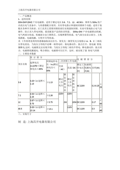
一、产品概述
1、适用范围
DSN-DMY\DMZ户内电磁锁,适用于额定电压3.6、7.2、12、40.5KV,频率为50Hz的户内高压电气设备中,与传感器配合使用,具有带电指示和强制闭锁两个功能,适用于装配在各种开关柜前、后门及其它需要闭锁的部位实现强制闭锁,从而可靠地防止电气误操作,防止误入带电间隔,提高配套产品的防误性能。
DSN□-DM户内电磁锁由机械、电气两部分组成,机械部分由门锁铁芯,压缩弹簧等组成。
电气部分由显示部分、主机线路板、电磁线圈、行程开关等组成。
其工作原理是利用传感器抽取高压信号,使发光二极管发光分别指示A、B、C三相高压带电状况,当高压主母线不论哪一相带电时,继电器动作,接点打开,使电磁铁线圈断电,这时,电磁锁无法实现开锁,当高压主母线三相均不带电,断电器动作,接点闭合,电磁锁线圈通电,吸合锁扣,电磁锁可以打开,这时,就实现了强制电气闭锁二、主要技术数据
制造:上海昌开电器有限公司
四、安装说明
1、使用该锁必须配置GSN、DXN系列高压带电显示装置的传感器,传感器的电压等级可根据用户要求选用,安装使用参见《高压带电显示装置》
正常操作步骤:
1、通入工作电压,电源指示灯亮,L1、L
2、L3三相指示灯不亮,说明高压回路不带电,该状态允许开锁。
2、将手柄向开锁相反方向转到位,按下电磁锁按钮,开锁灯亮,转动手柄(Y-右开,沿逆时针方向转动,Z-左开,沿顺时针方向转动)即可开锁。
3、若开锁指示灯不亮,显示部分指示灯亮,则表示不能开锁。
制造:上海昌开电器有限公司。
埋入型电磁锁说明书

12
18
5
38
10
15
2
32
12
18
5
38 (10000,10000ST型號選配)
10003M1000010000ST Unit: mm
埋入型電磁鎖安裝使用說明書
能微微調動,讓吸附板和電磁
鎖吸附面能緊密結合而無間隙
使吸力達到最高。
依照型號之不同,配件有所不同。
+
.
N.C.
Power Input Sensor Output
無法上鎖
問題 引起原因 如何排除
拉力不足
無訊號輸出
無電源
吸附板與電磁鎖吸附面有阻礙輸入功率不足
電磁鎖外部加二極體
確認電源線是否正確接到電磁鎖?確認電源供應器是否有電?
確認控制電磁鎖的門禁系統Relay 接點是否正確(N.C.)?
確認吸附板表面是否有變形?
確認吸附板是否加橡膠墊片?
確認吸附板與電磁鎖二者吸附面是否清潔無雜物?確認電磁鎖內部12/24VDC 規格是否設定正確?確認到電磁鎖的末端電壓/流是否設定正確?
電磁鎖內部已加保護裝置,請移除任何的二極體。
修正吸附板與電磁鎖的磁簧位置正確貼齊。
電源線與訊號線不可使用同一絞線,否則會互為干擾。
吸附板與電磁鎖接觸面不正確。
磁力锁说明书

1、吸力强,磁吸力为280kg。
本锁利用优质电工材料和先进加工工艺制造而成,外型美观,吸力强,无剩磁。
2、无机械磨损,克服一般要机械锁和电子锁缺陷,使用寿命长。
3、电源为12/24伏双直流电压入口。
4、启动电流0.45A,持续电流为0.45A,温升为室温+15℃。
锁体尺寸:250*47*25mm吸合力:280kg(静态直线)电压:DC12V\DC24V电流:480mA\240mA安装方式:明装状态指示灯:LED安全类型:断电开锁电磁锁的安装方法电磁锁(磁力锁)的标准安装方法[图]一.外开门的表面安装方法:(参照图一至图八)第一步:首先用螺丝刀打开盖板,再用六角扳手打边板,准备安装(见图一)第二步:拿出安装纸板,将纸板沿着虚线折叠按图二所示方法把纸板放到所需装锁的位置,然后把需要打孔的地方做上记号后打孔.第三步:A.继铁板的固定(参见图三)将内六角螺丝插入继铁板中,把橡胶华司置与两片金属华司之间,然后套在内六角螺丝上。
将继铁板插入门上打的三个孔中,同时把香菇头从门的另一面插入,利用六角扳手将继铁板锁在门上。
B.边板的固定(参见图三)把边板用两个半圆头螺丝固定在先前打孔的门框上(固定在边板的长形孔中)。
注意:不要将边板锁紧,让其能前后能移动以利于安位置的修正。
C.修正边板的位置使边板与继铁板的位置合适,目的使锁主体能与继铁板紧密的接触。
D:固定锁主体与边板锁紧边板的半圆头螺丝后,再锁上所有的沉头螺丝,然后再卸下半圆头螺丝,在适当的位置钻孔以便接线。
最后用六角扳手把锁主体锁在边板上。
(参见图四)第四步:按照说明书的指示接线。
第五步:盖上盖板,把小铝柱体塞进锁主体(参见图五)的螺丝孔中。
参见图六图七与图八所示为典型的外开门外置式的安装式样★安装注意事项在安装继铁板的时候,不要把它锁紧,让其能轻微摇摆以利于和锁主体自然的结合。
二、内开门的表面安装(ZL型支架的安装方法):解决外装磁力锁的内装问题。
内开门做表面安装时需要有辅助配件来协助安装,我们选用富有装饰性的优质进口铝材来制做这种安装配件:Z&L支架。
电磁锁安装说明书

Electromagnetic LocksInstallation ManualE-941SA-1K2DPSQ shownSECO-LARM Electromagnetic LocksHex-headmounting screws Steel washers x2 Armature screw Mounting plate Short self-tapping screws x2Door spacer Armature plate Rubber washer Long self-tapping screws x4 Sexnut boltArmature plateholder* Electromagnet Tamper caps x2Guide pins Parts List1x Electromagnet 1x Armature plate 2x Short self-tapping screws 1x Armature screw 2x Steel washers 1x Rubber washer 4x Long self-tapping screws 1x Sexnut bolt 2x Guide pins 1x Door spacer 2x Hex-head mounting screws 1x Mounting plate 2x Tamper caps2xHex wrenches1xArmature plate holder*1xManualSpecificationsHolding Force 600-lb1,200-lb.Operating voltage12/24 VDC Currentdraw 12VDC 500mA 24VDC 250mABond sensorSPDT relay, 3A@12VDC Door position sensor Reed switch, 0.2A@12VDC Operating temperature32°~120° F (0°~49° C)DimensionsMagnet913/16"x111/16"x1" (250x43x25 mm) 101/2"x27/16"x19/16" (267x62x40 mm) Armature71/4"x11/2"x 1/2" (185x38x12 mm) 71/4"x27/16"x5/8" (184x62x16 mm)Destructive attack Level I Line Security Level I Standby power Level I EnduranceLevel IVOverviewTypical Installation Plate Spacers "L" Bracket "L" Bracket and "Z" bracket "U" Bracket Armature Mounting Plate5.Do not install a diode in parallel with the electromagnetic lock as this may cause a delay whenreleasing the door as well as cause residual magnetism.6.The best location to install the electromagnetic lock is on the inside of the door that is beingsecured with the wiring concealed in the frame to prevent tampering with the unit.7.The minimum permissible wire size to be used shall not be less than 22AWG.SECO-LARM Electromagnetic LocksInstallationIdeal mounting locationDoor framee a hammer to lightly tap the two guide pins into the guide pin holes on thearmature plate.4.Place the template against the door and frame. Markwhere the holes are to be drilled. Door frameTemplateDoor5.Drill holes in the frame andthe door as shown on the template and in step #6 below. The smaller holes on the door should not go all the way through. Door frameDoorSee step#6 below6.Depending on the type of door being protected, drill holes according to the diagrams below:Drill a 5/16" hole (8mm) diameter holethrough the armature-plate side of the door for the armature screw. Then drill a 5/8" (16mm) diameter hole for the sexnut screw on the opposite side of the door.Drill a 1/4" hole (6.8mm) diameter and 1" (25mm) deep hole, tap for M8x1.25 thread.Drill a 5/16" hole (8mm) diameter hole in the door for the armature screw and drill a 1/2" (12.7mm) diameter and 1" (25mm) deep hole from the opposite side for the sexnut screw Reinforced doorSolid-core doorHollow metal door5/8" (16mm) 5/16" (8mm) 1/4" (6.8mm) for M8x1.25 thread 1/2" (12.7mm) 5/16" (8mm)7.Put a rubber washer between the two metal washers and place them over the armature screw between the armature plate and the armature plate holder. This allows the plate to pivot around the screw to compensate for door misalignment.The rubber washer is sandwiched between the two metal washers and all three are placed betweenthe armature plate and thearmature plate holder.Metal washers8.Tighten the armature screw enough so that the armature plate can withstand a break-in attempt, but loose enough so that thearmature plate can pivot slightly. Make sure the anti-spin guide pins are in the two guide pin holes.Guide pinsArmature screw TIPUse a thread-locking compound on the armature screw to ensure a long-lasting installation.Guide pins9.Screw the two short self-tapping screws through the mounting plate’s slotted holes, but do not over-tighten them. Keeping them loose will allow for adjustment of the plate so that the long edge of the mounting plate and the armature plate are parallel. See the diagram below.Armature plateMounting plate90°Short self-tapping screws10.Once the mounting plate position is correct, use the four long self-tapping screws to permanently mount the mounting plate. 11.Drill the cable access hole. Run the wiring through the cable access hole in the mounting plate and through the hole in thedoor frame.SECO-LARM Electromagnetic LocksInstallation (Continued)12.Remove the cover from the front of the electromagnet. Run the power leadsthrough the large cable access hole.13.Push the electromagnet against themounting plate so the electromagnet ends are flush with the ends of the mounting plate. Use the Allen wrench to screw the hex-head mounting screws through the bottom of theelectromagnet into the mounting bracket.14.Cut the wires so they are long enough to connect with the terminal block. Set the voltage using the selection jumpers based on your input voltage. NOTES•Failure to correctly set the input voltage may cause damage to the lock.•Connect switching devices like push-to-exitswitches between the power source and the positive terminal on the lock. Connecting switching devices to the negative terminal may cause a delay in unlocking. Position 2 jumpers on all four pins for 12VDC operation (default)Position a jumper on the two center pins for 24VDC operationVoltage Selection Jumpers15.Connect the power and other wires according to the wiring diagram on page 7. Test the unit. Then replace the front cover and install the hex-head tamper caps (x2).NOTE: This should be the very last step after all steps are confirmed, since once the tamper caps are in place, they are verydifficult to remove.SECO-LARM Electromagnetic LocksWiring DiagramNOTES• Connect switching devices like push-to-exit switches between the power source and the positive terminal of the lock. Connecting them to the negative terminal may cause a delay in unlocking.Maximum Distance from Power SourceFor a complete chart, visit 12VDC Minimum Wire GaugeWire Length 25ft 50ft 75ft 100ft 150ft 200ft 250ft 300ft 400ft 500ft 1,000ft Wire Gauge@500mA 2018 18 18 16 14 14 12 10 --- ---24VDC Minimum Wire GaugeWire Length 25ft50ft 75ft 100ft 150ft 200ft 250ft 300ft 400ft 500ft 1,000ft Wire Gauge@250mA 222222 20 18 18 16 16 14 14 14Wiring DiagramA fail-safe lock unlocks when power is lost so that, in case of an emergency such as a fire in the building, the fail-safe lock will automaticallyunlock allowing personnel to escape quickly.NOTE:All field wiring must be within the protected area.Maglock (Fail-safe)* (Indoor)Key Switch (Outdoor)N/C Exit Button (Indoor) Keypad (Outdoor)Access ControlUnitControl Device+ – Power Supply 12/24 VDCN.C.COM N.O. –+= 12VDC = 24VDCVoltage jumpersSECO-LARM Electromagnetic Locks TroubleshootingDoors lock, but can easily be forced open •Make sure the electromagnet and armature plates are properly aligned.•Make sure the contact surfaces of the electromagnet and armature plates are clean and free from rust.•Check the power leads with a meter, and make sure 12VDC or 24VDC is present.•Make sure the rubber washer is installed and free from damage.Delay in door releasing •The electromagnet is fitted with a metal oxide varistor to prevent interference, so do not install a second diode.•Ensure that the control device is connected between the power source and the positive terminal of the lockSECO-LARM® U.S.A., Inc.16842 Millikan Avenue, Irvine, CA 92606 Website: PITGW1 reserved.。
DSN-Y电磁锁使用说明书

DSN-Y电磁锁使⽤说明书⼀、概述DSN-Z DSN-Y型系列户内电磁锁是⼀种防⽌⾼压开关设备电器误操作的电控机构联锁装置。
主要适⽤于户内⾼压开关设备的前后柜门、隔离开关、断路器、接地线等需要闭锁部位实现联锁,防⽌误操作的发⽣,是发电和供电部门不可缺少的闭锁装置。
另外,为适应综合⾃动化变电站的需要,该系列电磁锁亦增加了锁内辅助接点。
能在锁具的合分位置给⽤户提供⼀对相应的开关接点,便于⽤户锁具相互联锁及综合⾃动化采样,避免了⾛空和,是现代化变电站设备理想的闭锁装置。
专利产品“电控锁”解决了综合⾃动化变电站中机械程序锁钥匙⽆法进⾏控制管理的缺陷。
⼆、主要技术参数1、⼯作电压交直流220V,110V2、辅助接点:电流≤3A电流≤6A(断路器闭锁)3、使⽤环境a、温度:上限+40℃下限-25℃-----10℃b、湿度:⽇平均值不⼤于95%⽉平均值不⼤于90%三、⽤途与使⽤范围本产品是⼀种防⽌⾼压开关设备电⽓误操作的电控机构联锁装置,主要供⾼压开关柜柜门及其它需要安全联锁的地⽅实现强制联锁,防⽌误⼊带电间隔和误操作的发⽣,是发电和供电部门不可缺少的闭锁装置。
四、正常⼯作条件周围空⽓温度:上限+40°C,下限:⼀般地区-10°C,⾼寒地区-25°C。
海拔⾼度:安装地区海拔不⾼于1000m。
环境湿度:空⽓相对湿度⽇平均不⼤于95%、⽉平均值不⼤于90%。
环境条件:⽆明显污秽、⽆易燃、易爆、化学腐蚀和盐雾及⽆经常性剧烈振动场所。
五、型号与含义户内电磁门锁选⽤基本参数(订货时请注明订货序号)六、安装使⽤说明电磁门锁安装步骤1.依次卸下⾯板安装螺杆的M5螺母、弹垫、平垫;2.从柜门外⾯将锁体的锁栓侧先放⼊开孔内,然后转动锁体使⾯板上的安装螺杆装⼊柜门上开好的?60mm孔内,并使锁⾯板与柜门板平整;3.从柜门内侧依次将平垫、弹垫、M5螺母装上锁⾯板上的M5螺杆,最后拧紧M5螺母。
电磁门锁使⽤说明(1)正常操作步骤a、揿下按钮,电源接通,电磁铁线圈受电动动作,动铁芯脱离锁栓挡块,开锁指⽰灯亮,表⽰允许开锁。
- 1、下载文档前请自行甄别文档内容的完整性,平台不提供额外的编辑、内容补充、找答案等附加服务。
- 2、"仅部分预览"的文档,不可在线预览部分如存在完整性等问题,可反馈申请退款(可完整预览的文档不适用该条件!)。
- 3、如文档侵犯您的权益,请联系客服反馈,我们会尽快为您处理(人工客服工作时间:9:00-18:30)。
一、产品概述
1、适用范围
DSN-DMY\DMZ户内电磁锁,适用于额定电压3.6、7.2、12、40.5KV,频率为50Hz的户内高压电气设备中,与传感器配合使用,具有带电指示和强制闭锁两个功能,适用于装配在各种开关柜前、后门及其它需要闭锁的部位实现强制闭锁,从而可靠地防止电气误操作,防止误入带电间隔,提高配套产品的防误性能。
DSN□-DM户内电磁锁由机械、电气两部分组成,机械部分由门锁铁芯,压缩弹簧等组成。
电气部分由显示部分、主机线路板、电磁线圈、行程开关等组成。
其工作原理是利用传感器抽取高压信号,使发光二极管发光分别指示A、B、C三相高压带电状况,当高压主母线不论哪一相带电时,继电器动作,接点打开,使电磁铁线圈断电,这时,电磁锁无法实现开锁,当高压主母线三相均不带电,断电器动作,接点闭合,电磁锁线圈通电,吸合锁扣,电磁锁可以打开,这时,就实现了强制电气闭锁二、主要技术数据
制造:上海昌开电器有限公司
四、安装说明
1、使用该锁必须配置GSN、DXN系列高压带电显示装置的传感器,传感器的电压等级可根据用户要求选用,安装使用参见《高压带电显示装置》
正常操作步骤:
1、通入工作电压,电源指示灯亮,L1、L
2、L3三相指示灯不亮,说明高压回路不带电,该状态允许开锁。
2、将手柄向开锁相反方向转到位,按下电磁锁按钮,开锁灯亮,转动手柄(Y-右开,沿逆时针方向转动,Z-左开,沿顺时针方向转动)即可开锁。
3、若开锁指示灯不亮,显示部分指示灯亮,则表示不能开锁。
制造:上海昌开电器有限公司。