HKD640微型客车设计(离合器及操纵机构及传动轴设计)(有exb图+中英文翻译)
汽车设计0204第二章 离合器设计 第四节 设计与计算

Gd ns 3 8D p K
切变模量G=83~103 N/mm24§2-Fra bibliotek离合器的设计与计算
二、圆柱弹簧 3.弹簧工作圈数ns,总圈数ns'
弹簧刚度K=20~45 N/mm
或
F F K f
Δf—分离过程弹簧的变形量Δf(mm) 单盘 1.1~2.6
双盘
3.0~3.6
ns' =ns +(1.5~2.0)
三、膜片弹簧
2.弹簧特性计算公式
Eh1 ln( R / r ) Rr 1 R r 2 F1 ( H 1 )( H )h 2 2 6(1 ) ( R1 r1 ) R1 r1 2 R1 r1
膜片弹簧的计算公式由碟形弹簧的计算 公式得来。
假设膜片弹簧在承载过程中,其子午断面刚 性地绕此断面上的某中性点O转动(图2-10)。
通过支承环和压盘加在膜片弹簧上的载荷 F1(N)集中在支承点处,加载点间的相对轴向变 形为λ1(mm) (图2-12b),则膜片弹簧的弹性特性 (图2-11)如下式表示。
§2-4离合器的设计与计算
§2-4离合器的设计与计算
§2-4离合器的设计与计算
4.计算弹簧自由状态的高度H
H=ns' d+(ns +1)δ+ Δf+f δ=0.5~1.5 f=F/K 分离状态下的最小长度 Hmin=(ns +1)δ+ ns' d mm
§2-4离合器的设计与计算
三、膜片弹簧的弹性特性
1.膜片弹簧的优点:见前述。
2.膜片弹簧的载荷与变形的关系
膜片弹簧自由状态下碟簧部分的内截锥高度 H; 膜片弹簧钢板厚度 h ; 自由状态下碟簧部分大端半径 R;
GD6360微型客车变速机构设计
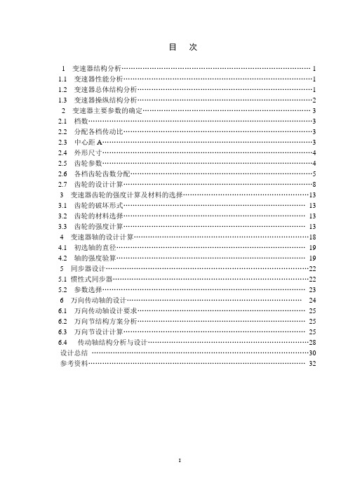
目次1 变速器结构分析 (1)1.1 变速器性能分析 (1)1.2 变速器总体结构分析 (1)1.3 变速器操纵结构分析 (2)2 变速器主要参数的确定 (3)2.1 档数 (3)2.2 分配各档传动比 (3)2.3 中心距A (3)2.4 外形尺寸 (4)2.5 齿轮参数 (4)2.6 各档齿轮齿数分配 (5)2.7 齿轮的设计计算 (8)3 变速器齿轮的强度计算及材料的选择 (13)3.1 齿轮的破坏形式 (13)3.2 齿轮的材料选择 (13)3.3 齿轮的强度计算 (13)4 变速器轴的设计计算 (18)4.1 初选轴的直径 (19)4.2 轴的强度验算 (19)5 同步器设计 (22)5.1 惯性式同步器 (22)5.2 参数选择 (23)6 万向传动轴的设计 (24)6.1 万向传动轴设计要求 (25)6.2 万向节结构方案分析 (25)6.3 万向节设计计算 (25)6.4 传动轴结构分析与设计 (28)设计总结 (30)参考资料 (32)1 变速器结构分析1.1 变速器性能分析变速器的功用是在不同的使用条件下,改变发动机传到驱动轴上的转矩和转速,使汽车得到不同的牵引力和速度,同时使发动机在最有利的工况范围内工作。
此外,应保证汽车能倒退行驶和在滑行或停车时,使发动机传动系保持分离。
需要时还要有动力输出功能。
变速器的设计需要在整车设计的总体原则下结合变速器要满足的具体功能展开。
因此本着好用、好造、好修的总原则,力求产品通用化、标准化、系列化。
对变速器提出如下的基本要求:1)正确选择挡数和传动比,保证汽车有必要的动力性和经济性指标;2)设置空挡,以使发动机能启动怠速、换档、切断发动机动力向驱动轮的传输;在滑行或停车时使发动机和传动系彻底分离;3)设置倒挡,使汽车能倒退行驶;4)设置动力输出装置,能进行功率输出;5)换档迅速、省力、方便,以便缩短加速时间并提高汽车的动力性能;6)工作可靠,汽车行驶中,变速器不得有跳挡、乱挡以及换挡冲击等现象发生;7)变速器还应当满足效率高,噪声低,体积小,质量轻,制造容易,成本低等要求、维修方便等要求。
汽车零部件中英文对照表
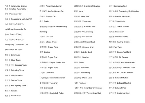
汽车类Automobile English整车Finished Automobile轿车Passenger Car休旅车Recreational Vehicle (RV) 小型商用车(3.5吨以下)Light Duty Commercial Car (Less Than 3.5 Tons)大型商用车(3.5吨以上)Heavy Duty Commercial Car (More Than 3.5 Tons)散装车Bulk Truck搅拌车Mixer Truck环境卫生车Garbage Truck液罐车Refueling Truck倾卸车Dumper Truck曳引车Tractor Truck消防车Fire Fighting Truck堆高机Forklift拖板车Pallet Truck 运钞车Armor Cash Carrier冷气客车Air-Conditioned Car冷冻车Freezer Car拖车Trailer车体打造(改装) Car Body Building(Refitting)瓦斯车LPG Car底盘车Chasis Truck引擎零件Engine Parts引擎Engine引擎波司Engine Bush引擎修理包Engine Gasket Kits引擎零件Engine Parts凸轮轴Camshaft凸轮轴链轮Sprocket Camshaft皮带张力器Tensioner曲轴Crankshaft曲轴皮带盘Crankshaft Pulley曲轴轴承片Crankshaft Bearing汽门Valve汽门座Valve Seat汽门摇臂Valve Arm汽门摇臂盖Rocker Cover汽门弹簧Valve Spring汽门导管Valve Guide汽缸头(盖) Cylinder Head汽缸衬套Cylinder Liner汽缸体Cylinder Block波司垫片Washer活塞Piston活塞肖Piston Pin活塞环Piston Ring活塞衬套Piston Liner飞轮Flywheel飞轮环齿轮Ring Gear of Flywheel时规炼条/皮带Timing Chain/Belt连杆Connecting Rod连杆轴承片Connecting Rod Bearing摇臂轴Rocker Arm Shaft汽门锁Valve Cotter止推垫片Thrust Washer共鸣箱Resonator喷油嘴Injection Nozzle燃料系统Fueling System油箱Fuel Tank油箱浮筒Gauge Fuel Tank空气滤清器Air Cleaner空气滤清器盖Air Cleaner Cover空气滤清器导管Air Intake Tube空气滤蕊Air Cleaner Element消音器Exhaust Muffler排气歧管Exhaust Manifold排气管Exhaust Pipe进气歧管Intake Manifold节流阀Throttle Valve燃油管Fuel Pipe燃油帮浦Fuel Pump燃油滤清器Fuel Filter触媒转化器Catalytic Converter柴油车黑烟净化器Diesel Particulate Filter时规炼条/皮带外盖Timing Chain/Belt Cover燃料系统Fueling System废气回收管EGR Tube冷却系统Cooling System水箱Radiator水管Water Hose水箱水管Radiator Hose水帮浦Water Pump水箱风扇Radiator Fan风扇Fan副水箱Auxiliary Radiator 节温器Thermostat调节器Regulator水箱支架Radiator Mounting冷却系统Cooling SystemA/C风扇A/C Fan润滑系统Lubrication System油底壳Oil Pan自排车用滤油器Oil Filter forAutomaticTransmission机油尺Oil Level Gauge机油帮浦Oil Pump机油滤清器Oil Filter机油滤网Oil Strainer润滑系统Lubrication System机油尺导管Oil Level Gauge Tube空调系统Air-conditioning System冷气总成A/C Assembly冷气配管A/C Hose冷气导风管A/C Duct冷气压缩机A/C Compressor冷凝器A/C Condenser暖气总成Heater Assembly鼓风机Blower Assembly蒸发器Evaporator冷媒管A/C Pipe储液瓶A/C Receiver空调相关零件A/C RelatedComponents空气清净机Air Purifier空调滤网A/C Filter空调系统Air-conditioning System提速器Actuator车身钣金件Body & Stamping Parts引擎支撑Engine Mounting引擎盖Engine Hood车身Car Body车门Door Panel车顶板Roof底盘及其另件Chassis and RelatedParts底盘车架Frame门框Sash保险杆Bumper钣金件Stamping Parts叶子板Fender横梁Cross Member行李箱盖Trunk Lid车柱Pillar车身钣金件Body & Stamping Parts支架Bracket补强板Reinforcement Plate底盘系统Chassis System下臂Lower Arm上臂Upper Arm手剎车拉柄Parking Brake Lever支柱总成Strut Assembly方向盘Steering Wheel比例阀Proportional Valve主轴、副轴Mainshaft / Countershaft平衡杆Stabilizer Bar扭力杆Torsion Bar剎车分泵Brake Cylinder剎车来令片Brake Lining Shoe剎车油管(软) Brake Hose剎车油管(硬) Brake Tube剎车真空倍力器Brake Vacuum Booster剎车总泵Brake Master Cylinder后轴总成Rear Axle Assembly动力方向系统Power Steering System动力转向油管Power Steering Hose动力转向帮浦Power Steering Pump控制拉线Control Cable排档杆Shift Lever排档头Knob 球形接头Ball Joint等速接头C.V. Joint传动轴Propeller Shaft叶片弹簧Leaf Spring鼓、碟式剎车器Drum / Disc BrakeAssembly鼓式剎车盘Brake Drum碟式剎车盘Brake Disc辅助气囊Air Bag踏板Pedal齿轮Gear横拉杆接头Tie-Rod End螺旋弹簧Coil Spring避震器Shock Absorber转向连杆Steering Linkage转向节臂Knuckle转向齿轮箱Steering Gear Box转向机柱Steering Column转向总成Steering Assembly离合器分泵Clutch Cylinder离合器片Clutch Disc离合器外壳Clutch Case离合器总成Clutch Assembly离合器总泵Clutch Master Cylinder离合器释放轴承Clutch ReleaseBearing变速箱Transmission Box变速箱外壳Transmission Case曳力杆Trailing Arm避震器前后活塞杆Piston Rod of Frontand RearShock Absorber底盘系统Chassis System自排变速箱修理包AutomaticTransmissionGasket Kits齿条Gear Rack剎车真空管Brake Boost VacuumTube车轮系统Wheeling System轮毂Wheel Hub轮胎Tire轮胎汽门嘴Tire Valve中文产品名称Chinese英文产品名称English轮圈Wheel Disk轮圈盖Wheel Cover内胎(含内衬) Inner Tire (Flap)车轮系统Wheeling System电装品Electrical Parts电瓶Battery中央门控Central Door Lock分电盘Distributor火星塞Spark Plug汽车用电子钟Digital Clock汽车音响Car Audio防盗器Car Burglar Alarm雨刷及雨刷连杆Wiper / Linkage保险丝座Fuse Seat保险丝Fuse洗涤壶Windshield Washer配线Wire Harness马达类Motor高压线组Ignition Cable喇叭Horn发电机(零件) Alternator (Components) 开关类Switch蜂鸣器Buzzer预热塞Glow Plug仪表Combination Meter灯泡Bulb灯类Lamp点火线圈Ignition Coil 继电器Relay倒车雷达Reverse Sensor电池充电器Battery Charger闪光器Flasher省电器Energy Saving Unit端子Terminal电动座椅装置Power Seat Unit马达零件Motor Components电装品Electrical Parts汽车用光盘Car CD汽车用液晶显示器Car LCD调整器Regulator整流器Rectifier电子点火器Ignition Module倒车显示器Rear View Display定速器Cruise ControllerHID车灯安定器组合HID BallastComplete Set forHeadlightsLED 灯LED Lamp车灯控制器Lighting Controller点火线圈模块Ignition Coil Module外装品Exterior Parts水箱饰罩Radiator Grille天线Antenna车身护条Side Protector防撞护垫Bumper Pad后视镜Door Mirror装饰贴纸、标志Ornament Mark轮弧Fender Trim挡泥板Mud Guard扰流板Spoiler前防撞杆Guard Assy (Front)后防撞杆Grard Assy (Rear)外装品Exterior Parts内装品Interior Parts仪表板Instrument Panel中央置物箱Console孔塞Grommet Plug地毯Floor Mat安全带Seat Belt车门扶手Door Armrest车门把手Door Handle车门锁Door Lock车顶内衬Roof Lining车窗升降摇柄Window Lifter Handle车窗升降机Window Lifter防水衬条Weatherstrip油量表Fuel Gauge门饰板Door Trim室内镜Room Mirror音响喇叭盖Speaker Cover(电动)座椅(Electric) Seat顶蓬Headlining烟灰缸Ashtray各类隔音垫All Kinds of Silencer饰板/饰条Garnish / Trim仪表饰板Instrument Panel Garnish遮阳板Sunvisor压条Moulding点烟器Cigar Lighter备胎板Trim for Spare Tire天窗Sun Roof后置物板Rear Parcel Shelf后舱室饰板Rear Trunk Trim内装品Interior Parts仪表板支架Instrumental Panel Mounting其它Others随车工具Tools千斤顶Jack尼龙绳、特多龙绳Nylon Rope生产、检测及涂装设备Production,Test & Painting Equipment各类孔盖Cap、Cover扣具Cargo Lash夹片、管束Clamp, Clip油土与基准模型Clay Model andMaster Model油封Oil Seal门铰链Door Hinge故障标志Reflector玻璃类Glass修理业Repairing & Maintenance粉末冶金Powder Metallurgy轴承Bearing塑料件Plastic Parts隔热材Heat Insulator电子件Electrical Parts垫片类Seal、Gasket、Washer、Packing碳刷Carbon Brush管类Pipe, Hose, Tube铜套类Bushing弹簧SpringEnglish模、夹、治、检具Die, Fixture, Jig,CheckingGauge橡胶件Rubber Parts帮浦类Pump螺帽/螺栓/螺丝Nut/Bolt/Screw锻造件(加工) Forging Parts(Processing)滤清器类Filter锁Lock镜类Mirror铸造件(加工) Casting Parts(Processing)引擎盖铰链Hinge of Engine Hood行李箱铰链Hinge of Trunk Lid保险杆支撑Mount of BumperCAD/CAM车身设计CAD/CAM CarBody Design汽车清洁保养用品Cosmetics forAutomobile涂料Paints合成木材Synthetic Wood电磁阀Solenoid Valve热水阀Heater Valve冷煤电磁阀Refrigerate Solenoid valve玻璃滑槽Glass Run双面胶带Acrylic Foam Tape触媒转换器缓冲绵Catalytic ConverterMate黑烟过滤器Diesel Particle Filter车用灭火器Extinguisher零组件用材料Components Materials汽车用行动电话Car Hand-free MobilePhone汽车保全系统Car Security System汽车导航系统Car Navigation System人造革Artificial Leather铭板Nameplate汽车用计算机Car Computer无线电胎压侦测仪Wireless Tire Monitor汽车内装用牛皮Leather for Car Interior打蜡机Buffer (Car Polisher)金属表面处理(材料) Metal Surface Treatment(Material)插接件Connector Clip胎压不足警示器Tire Low Pressure Indicator温度感应器Water Temperature Sensor油压感应器Oil Pressure Sensor机油Engine Oil中文产品名称Chinese英文产品名称English自动变速箱油Automatic TransmissionOil油品添加剂Oil Additive热处理Heat Treatment自行车类Bicycle整车Finished Bicycle一般自行车Regular Bicycle三轮车Tricycle协力车Tandem Bicycle城市车ATB孩童车Junveniles Bicycle室内运动车(健身车) Exerciser单轮车Unicycle无链式自行车Chainless Bicycle登山车Mountain Bicycle越野车Trekking Bicycle跑车(自由车)Racing Bicycle电动自行车Electrical Bicycle折叠式自行车Folding Bicycle海滩车Beach Bicycle(电动)滑板车(Electric) Kick BoardScooter其它特种自行车OtherSpecial-purposeBicycles避震脚踏车Suspension Bicycle传动件Transmission曲柄组Chainwheel & Crank飞轮Flywheel链条Chain变速杆Shift Lever变速器Derailleur电动自行车马达Electric Bicycle Motor电动自行车控制器Electric BicycleDriver齿轮箱Gear Box车轮及剎车Wheel and Brake轮胎Tire夹式剎车器Caliper Brake快拆Quick Release花鼓Hub & Free HubEnglish液压式剎车器Hydraulic Brake脚剎车器Coaster Brake碟式剎车器Disk Brake轮圈Rim辐条/辐帽Spoke/Nipple悬臂式剎车器Cantilever Brake控制拉线Control Cable剎车来令片Brake Lining Shoe配件Accessories铃Bell反光片Reflector水壶架Bottle Cage打气筒Floor Pump商标贴纸Sticker货架Luggage Carrier速度表Speed Meter喇叭Horn电灯Dynamo / Lighting Set辅助轮Training Wheel挡泥板Mud Guard / Fender头盔Helmet锁Lock链盖Chain Cover篮Basket后视镜Rear Mirror车体Body车架Frame把手Handle Bar中轴组件(天心)Bottom Bracket Parts 车手带Handle Strap车头组件Headset 前叉Front Fork前叉肩Fork Crown后叉端Rear Fork End座杆Seat Post座杆束Seat Post Clamp停车支架Kickstand接头Lug & Shell辅助把手Bar End竖管Stem螺帽/螺栓/螺丝Nut/Bolt/Screw避震前叉Suspension Fork避震器Shock Absorber三通管3-way Pipe五通管5-way Pipe车架材料Frame Materials其它Others座垫Saddles水壶架Bottle Cage夹器固定座Pivot定趾器Toe Clip闪光灯Flasher趾夹带Toe Strap把手套Grip塑料件Plastic Parts脚踏板Pedal碳刷Carbon Brush弹簧Spring轮圈盖Wheel Cover锻造件(加工) Forging Parts(Processing)导线Cable模、夹、治、检具Die,Fixture,Jig &CheckingGauge橡胶件Rubber Parts生产、检测及涂装设备Production,Test& PaintingEquipment座垫套Saddle Cover涂料Paints充电器Charger温度记录器Temperature Recorder电池容量计Battery Capacity Indicator电动自行车电路设计Electric BicycleCircuitDesign电动自行车电池组Electric BicycleBattery Set机车类Motorcycle整车Finished Motorcycle50CC以下机车Less Than 50CCMotorcycle50~150CC机车50~150CCMotorcycle150CC以上机车More Than 150CCMotorcycle残障专用车Motorcycle for Handicap电动机车Electric Motorcycle其它电动辅助车辆Other Electric AuxiliaryVehicles多功能休闲车ATV引擎零件Engine Parts汽缸Cylinder化油器Carburetor引擎Engine引擎零件Engine Parts引擎盖Engine Cover水箱Radiator火星塞Spark Plug凸轮Cam凸轮轴Camshaft凸轮轴链条Cam Chain凸轮链条张力器Cam Chain Tensioner曲轴Crankshaft曲轴箱Crankcase曲轴箱盖Crankcase Cover 汽门Valve汽门座Valve Seat汽门导管Valve Guide汽缸头Cylinder Head汽缸头侧盖Cylinder Head Side Cover油帮浦Oil Pump后轮驱动座Rear Wheel Drive Seat活塞Piston活塞肖Piston Pin活塞环Piston Ring连杆Connecting Rod涡轮增压器Turbo-Supercharger脚踏起动机杆Kick Starter齿轮变速零件Gear Shift Parts机油冷却器Oil Cooler离合器Clutch离合器座Clutch Plate离合器杆Clutch Lever变速箱Transmission Box油管Fuel Pipe汽门锁Valve Cotter火星塞盖Plug Cover齿轮衬套Gear Bushing曲轴肖Crank Shaft Pin炼条调整器Tensioner节流阀Throttle Valve离合器来令片Clutch Lining齿轮轴Gear Axle马达轴Motor Axle传动轴Transmission Axle车体及电装Body and Electrical Parts灯类LampC.D.I.总成C.D.I. Unit Assembly工具Tool中心盖Center Cover反光片Reflector引擎罩盖Air Shroud / Cylinder方向把手Steering Handle主滑动模轮组件Primary SheaveAssembly主脚架Main Stand交流发电机(零件) A.C. Generator(Components)行李箱Luggage Box冷却风扇Cooling Fan把手盖Handle Cover车架Frame车体盖Body Cover拉杆Handle Lever油杯Fuel Cup Assembly油箱Fuel Tank空气滤清器Air Cleaner剎车来令片Brake Shoe剎车鼓Brake Drum剎车盘Brake Disk剎车踏板Brake Pedal剎车总成Brake Assembly前叉Front Fork前叉顶梁Fork Top Bridge前护盖Front Fender后视镜Back Mirror后悬吊系统Rear Suspension 风扇盖Air Shroud飞轮Flywheel座垫Seat侧脚架Side Stand侧盖Side Cover排气消音器Exhaust Muffler后架Carrier喇叭Horn无段自动变速系统C.V.T.发电机Alternator传动轴总成Secondary Sheave Assembly 摇臂Rocker Arm煞车踏板Brake Pedal节流把手Throttle Grip脚踏板Board / Footrest脚踏杆Kick Crank Assembly电圈Starter电瓶Battery配线Wire Harness碳刷Carbon Brush仪表Meter调整器Regulator轮胎Tire轮圈Wheel Disk轮毂Wheel Hub导线Cable挡泥板Fender机车链轮Chain灯泡Bulb燃油滤清器Fuel Strainer Assembly避震器Shock Absorber点火线圈Ignition Coil转向主干Steering Stem Comp链条Chain链条盖Chain Case继电器Relay触媒转化器Catalytic Converter排气管Exhaust Pipe吊架Hanger控制拉线Control Cable活性碳罐Canister油箱浮筒Tank Float机油浮筒Oil Float档位调整器Gear Position Indicator端子Terminal电动机车控制器Electric MotorcycleDriver把手座Grip Holder马达类Motor马达零件Motor Components避震器前后活塞杆Piston Rod of Frontand RearShock Absorber其它Others油封Oil Seal舌簧阀Reed Valve钣金件Stamping Parts防盗器Burglar Alarm闪光器Flasher贴纸Sticker轴承Bearing开关类Switch塑料件Plastic Parts电子件Electrical Parts垫片Gasket管类Tube or Pipe弹簧Spring模、夹、治、检具Die, Fixture, Jig, CheckingGauge辐条/辐帽Spoke/Nipple齿轮Gear橡胶件Rubber Parts帮浦类Pump螺帽/螺栓/螺丝Nut/Bolt/Screw锻造件(加工) Forging Parts (Processing)滤清器Filter铸造件(加工) Casting Parts (Processing)锁Lock生产、检测及涂装设备Production,Test & PaintingEquipment铭板Name Plate油土及基准模型Clay Model and Master Model 涂料Paints握把Grip置物袋Carriage Bag机车座垫用牛皮Leather for Motorcycle Seat铁路车辆类Railroad Vehicle铁路车辆制造及修理Railroad Vehicle Manufacture& Repair铁路车辆零件Railroad Vehicle Parts。
实用微型客车设计-车架、制动系设计英文翻译
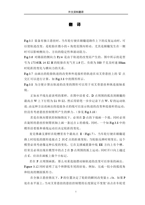
翻译Fig.3.5 装备有独立悬挂时,当车轮行驶在颠簸道路作上下的反复运动时,可以使轨迹改变,是轮胎在微小的α角度范围内转动。
尤其是颠簸发生在一侧时可以影响侧向力、方向的稳定性和滚动阻力。
Fig.3.6 对路面的侧向力Fy.w是由于轨迹的改变而产生的。
图中所示的是型号为175/65R 14 82 H的轮胎在充气至1.9巴、负荷为380千克及时速80km 时轮距的变化与横向力的关系。
Fig.3.7 由画出的轮胎轨迹的改变和外连接杆的轨迹在双叉骨悬挂上的U点交汇可以进行计算,如Fig.3.8中的图形所示。
Fig.3.8 为方便计算出轨迹的改变的图形可以用于双叉骨悬挂和纵连接轴系统。
正如水平线先前表明的那样,在图中沿着C、D点周围的弧直到颠簸的最高点W上下行程为S1和S2。
然后用铅笔一步步记录下点W、U的运动轨迹。
由这种方法而画出的连接各点的线可以显示轨迹的改变和连接杆的运动,但没有考虑悬挂控制臂所产生的弹力。
(参见Fig.3.18)若是在纵向臂状控制轴情况下,必须在D点的下端画一个弧,同时必须在旋转的悬挂控制臂状轴上画一条过点1的垂线。
同时,一个如Fig.3.8中的模形沿着弧和垂线运动以决定轮距的变化。
麦克佛森支撑杆在轮槽里有个最高点E(Fig1.7),当车轮行驶在颠簸道路上时较低的圆形连接点2 到C点的距离变短,当轮胎反弹时则变长。
这个模型必须考虑像这种长度的变化,它在支撑减震器中线EE方向上有个槽。
经常且必须出现在模型中的点2在D点周围的弧上运动,同时开口向上越过点C。
应该在画板上做个小标记。
若在P点周围画弧,那么双重连接摆动轴轨迹的改变可以容易的画出。
Figure 3.12同时说明了这个和降低车尾的好处。
例如,完成一较小的弧度角和较高的侧面弧形力。
在全独立悬挂情况下,P的位置决定了轮距的瞬间改变量±⊿b。
如果P 处在水平面上,当双叉骨悬挂的悬挂控制臂的长度固定不变使`该点在车轮受挤压或反弹时从一边到另一边作水平运动时(Fig.3.13),轮距的改变可以完全得到避免。
中英文文献翻译—离合器的简单介绍
附录A对于手动挡的车型而言,离合器是汽车动力系统的重要部件,它担负着将动力与发动机之间进行切断与连接的工作。
在城市道路或者复杂路段驾驶时,离合器成了我们最频繁使用的部件之一,而离合器运用的好坏,直接体现了驾驶水平的高低,也体现了对于车辆保护的好坏。
正确使用离合器,掌握离合器的原理以在特殊情况下利用离合器来解决问题,是每个驾驶手动挡车型的车友应该掌握的。
所谓离合器,顾名思义就是说利用“离”与“合”来传递适量的动力。
离合器由摩擦片,弹簧片,压盘以及动力输出轴组成,布置在发动机与变速箱之间,用来将发动机飞轮上储存的力矩传递给变速箱,保证车辆在不同的行驶状况下传递给驱动轮适量的驱动力和扭矩,属于动力总成的范畴。
在半联动的时候,离合器的动力输入端与动力输出端允许有转速差,也就是通过其转速差来实现传递适量的动力。
离合器分为三个工作状态,即不踩下离合器的全连动,部分踩下离合器的半连动,以及踩下离合器的不连动。
当车辆在正常行驶时,压盘是紧紧挤靠在飞轮的摩擦片上的,此时压盘与摩擦片之间的摩擦力最大,输入轴和输出轴之间保持相对静摩擦,二者转速相同。
当车辆起步时,司机踩下离合器,离合器踏板的运动拉动压盘向后靠,也就是压盘与摩擦片分离,此时压盘与飞轮完全不接触,也就不存在相对摩擦。
最后一种,也就是离合器的半连动状态。
此时,压盘与摩擦片的摩擦力小于全连动状态。
离合器压盘与飞轮上的摩擦片之间是滑动摩擦状态。
飞轮的转速大于输出轴的转速,从飞轮传输出来的动力部分传递给变速箱。
此时发动机与驱动轮之间相当于一种软连接状态。
一般来说,离合器是在车辆起步和换挡的时候发挥作用,此时变速箱的一轴和二轴之间存在转速差,必须将发动机的动力与一轴切开以后,同步器才能很好的将一轴的转速保持与二轴同步,挡位挂进以后,再通过离合器将一轴与发动机动力结合,使动力继续得以传输。
在离合器中,还有一个不可或缺的缓冲装置,它由两个类似于飞轮的圆盘对在一起,在圆盘上打有矩形凹槽,在凹槽内布置弹簧,在遇到激烈的冲击时,两个圆盘之间的弹簧相互发生弹性作用,缓冲外界刺激。
汽车离合器中英文对照外文翻译文献
汽车离合器中英文对照外文翻译文献(文档含英文原文和中文翻译)Fethermal analysis of a ceramic clutch1. IntroductionAbrasive dry running vehicle clutches are force closure couplings. Torque and speed transmission are ensured by the frictional force generated between two pressed surfaces. Reasons for the application of ceramic as a friction medium include good heat and wear resistance properties, which provide the opportunity to drive higher pressures, and a low density. Thus, an increasing power density is enabled with a parallel minimization of construction space.Measurements with a first prototype of a clutch disk using ceramic facings were performed at Karlsruhe University in a laboratory specialized in passenger car drive system testing. In the course of analysis the finite element (FE) model was to be constructed with the knowledge of measurement data and measurement conditions. Calculations were intended to determine the temperature distribution of the clutch disk and its environment at each moment in time corresponding to measurements. It is essential to be familiar with the temperature range in order to examine the wear characteristics of the system. Thus,important information is derived from measurement data. In critical load cases, the highest expected temperatures must be forecast in space and time in order to protect measuring instruments close to the location of heat generation.The goal of this study is to analyze and modify the clutch system to provide better operating conditions by improving the heat conduction and convection of the system or to increase the amount of the energy converted into frictional heat. Furthermore, it is desired to find better design solutions for more efficient clutch systems.Calculations were performed by the Cosmos Design Star software. During model development, great care had to be taken for proper simplification of geometry, the selection of element sizes, and the correct adjustment of time steps due to the substantial hardware requirements for transient calculations. Changes in thermal parameters such as the surface heat convection coefficient and thermal load had to be taken into consideration on an on-going basis in terms of time and location. The two sides of the analyzed test clutch system can only be managed by two independent models linked by heat partition, according to the hypothesis that the contact temperature must be identical on both sides while there is proper contact between them and its value must be adjusted by iteration. Calculations revealed that the heat partition changed by cycle and it differed along the inner and outer contact rings. As a result of the different cooling characteristics between the ceramic and steel side, a heat flow is launched from the ceramic side to the steel side. This heat flow was also determined by iteration, its value also changes by cycle and differs along the inner and outer contact rings.2. First prototype of a clutch using engineering ceramics as friction materialThe examined clutch disk was developed according to the “specific ceramic” product development process established at the Institute for Product Development (IPEK) at the University of Karlsruhe. This development process already has the possibility for connection to a real transmission shaft; further, it has a cushion spring device for the facings allowing good start behaviour. Abrasive clutches must comply with the following basic requirements:●high torque transmission according to high friction coefficients,●high comfort (no vibrations through self-induced chattering),●homogeneous temperature distribution,●low wear characteristic.A critical element of the switch is the abrasive disk.With regard to the design utmost care must be taken to select the right material. A high and constant friction coefficient,,wear resistance and thermal resistance are desired characteristics. The clutch disk has instead of the generally applied ring-shaped abrasive inlet two rows of SSIC (as sintered) ceramic pellets. These pellets are placed on 6 separate segments. The segments are fixed to the central hub by rivets. Each segment consists of 4 plates, 2 working as facing springs and 2 as carriers.3. MeasurementsMeasurements were performed at the department of power train development of the Institute for Product Development (IPEK) at the Karlsruhe University (TH) Research University, where a category IV component test rig is used for tests of new frictional materials and examinations of new materials in real clutch disks. Real conditions are applied by the simulation of driving resistance (e.g. starting in the plane, starting at the hill). It is a component test rig leveled on the fourth position of the tribological testing environment.In order to give an idea of dimensions: the equipment length is about 4-5m. The two electric motors and the axial force are controlled independently by computer; thereby many operational states can be realized. This enables the equipment to complete a myriad of tribological measurements all while properly modeling the operation of a clutch disk in a passenger car. It is also equipped with an automatic IT measurement system. Measurable quantities include the following:●two heavy-duty electric motors (150 KW, Baumuller DS 160L-305),●device suitable for exerting axial force,●torque meter (Manner Sensortelemetrie MF100),●axial force meter,●steel disk in friction,●replaceable head to affix the device to be tested,●temperature along two different radii at 0.4mm below the abrasive surface of the steeldisk (Omega HJMTSS-IM100U-150-2000,J-typeiro-constantan thermocouples),●revolutions per minute for both sides (Polytene LSV 065).The greatest challenge out of these is temperature measurement as we would like to know the temperature of the revolving steel disk. The two thermoelements placed in the steel disk forward data to the computer through a wireless blue tooth system and are placed 0.4mm below the abrasive surface of the steel disk on the two opposite arcs of the clutch disk.3.2. Measurement processDue to component analyses and cost reduction only one side of the clutch disk is mounted with ceramic facings. Thus, the clutch disk and its fitting will be referred to as the ceramic side, and the abrasive steel disk with its environment revolving together will be referred to as the steel side. In the course of measurements, data were collected at a sampling frequency of 100 and 1000HZ. Measurements were conducted according to the time curves.The measurement starts by increasing the revolutions per minute of the steel side (the driving side) to a specific value (1500 rpm here). Then the ceramic side (the driven side), held at zero rpm, is pushed towards the steel disk and the axial force is applied until a designated value is reached (nominally 4200N here). Upon reaching the designated axial force the ceramic side is released and the two sides start to synchronize. A few seconds after synchronization, the axial load is discontinued and after some time both the steel and the ceramic sides—revolving at the same speed—are slowed down. This is deemed to be one measurement cycle. Ten cycles are completed in the course of a single measurement. During application of the axial force the ceramic side is held at zero rpm until the desired force is reached to ensure synchronization occurs at nearly the same time of each cycle. This is unfavorable from the viewpoint of both measurements and calculations. Measurements are usually conducted by changing only 3 parameters: the speed, the axial load and the inertia. The following figures are applied in various combinations:●speed n: 700, 1100 and 1500 (rpm),●axial force F: 4200, 6400 and 8400 (N) andinertia I: 1, 1.25 and 1.5 (kgm2).Experimental measurements are launched with approx.10-15 min intervals, during which the system cools down to about 30-40 1C. This makes calculations difficult, as the exact temperature distribution of the system is not known at the commencement of the measurement. However, it can be assumed that a period of 10-15min is sufficient for a nearly homogeneous temperature distribution to be produced. The parameters for the following simulation have been chosen for an intermediate case with a speed n =1500 rpm, an axial force F = 4200 N and an inertia I = 1 kg m2.4. Calculations of heat generationThe mechanical energy consumed during the friction of two bodies is transformed into heat. The generated heat can be calculated by the following simple formula: Q =μ·ν·F [W] .where m is the the frictional coefficient; v is the sliding velocity; F is the force perpendicularly compressing the surfaces. And the heat flux density per surface unit is q=μ·ν·p [Wm2].where p is the the pressure calculated as a ratio of the force and the contacting surface. As the ceramic tablets are placed at two different radii along the clutch disk, the heat generated must be calculated separately for each radii. Sliding can be divided into two sections. In the first section, the ceramic side is kept in a stationary position by braking, meanwhile the axial load is increased; therefore compression changes in the course of time while the speed difference between the two sides is constant. In the second section (at synchronization) the speed difference is equalized while the force value is constant, so velocity changes in time. On the basis thereof, the heat generated is.The nominal contact area is the aggregate of the contacting surfaces of the 24 and 18 ceramic tablets on the given ring. The diameter of ceramic tablets is:.Calculations were performed for the load case to be characterized by the following parameters:.Based on experimental measurements a constant friction coefficient of 0.4 was established..The velocity can be calculated with the knowledge of the radius and the speed..Surface pressure can be calculated as a ratio of the axial force and the contacting surface. This produces the same figure for each ceramic pellet, assuming an even load distribution..Thus, the maximum values of the generated heat are.In the first section of sliding, the generated heat is rising due to the increase of the load force; in the second section, it is decreasing due to the equalization of the speed difference. It is necessary to know the time of each sliding section in order to be able to specify the generated heat time curve. These can be determined from measurement dataseries. Synchronization time can be easily determined from the speed of the ceramic side. Speed increase is linear. Force increase is non-linear. For the sake of simplicity, force increase was substituted by a straight line in calculations so that the area below the straight line is nearly identical with the area measured below the curve. Thus, the time difference between the two terminal points of the straight line is the time of the first sliding section.The above-mentioned method was applied for each cycle and their average was specified. Based on these results, the following values were determined for sliding times:.Now the time curve of heat generation can be produced. The same curve was used in each cycle as there were no significant differences between parameters in each cycle. The generated heat-calculated this way-will appear as thermal load in the thermal model. It must be distributed appropriately between the contacting surfaces by taking into consideration heat partition. Heat partition requires the contact temperatures to be identical at both surfaces. Correct adjustment requires repeated iterations.有限元热分析的陶瓷离合器1 引言磨料空转车辆离合器是力封闭联轴器。
4座微型客货两用车设计外文资料 翻译
变速器尽管现代汽车所使用的变速器各式各样,但它们的工作原理是大致相同的。
变速器有液力变速器,也有由制动器和离合器控制的行星齿轮组,行星齿轮组可以提供两个或三个前进挡。
变速器可以提供不同数值的传动比,对于发动机这很重要。
发动机低速运转时传递动力不大。
汽车起步时又要求输出扭矩较大,这使发动机就必须高速运转。
驾驶员挂上第一档,此时使发动机以高速运转:其传动比为发动机的曲轴转12圈,后车轮转一圈。
这时发动机提供的大功率使汽车启动并快速加速。
然后,驾驶员换二档(分开离合器,使变速器中的齿轮顺利换档),此次后二档使汽车加速到更高的速度,速比为8:1,最后换到第三档,在这一档中,动力通过变速器直接传递,传动轴与发动机曲轴转速一致。
第三档的传动比为1:1。
另设有一倒档,在这一档中,传动轴将朝反方向传动,从而使汽车实现倒向行驶。
四轮驱动在美国,虽然更多的消费者不愿再使用运动型多功能车(休闲越野车SUV),而更倾向于选择轿车和功能交叉型车,但他们依然不愿放弃全轮驱动(AWD)系统,因为对他们来说,这是一个安全的系统。
在最近一次对休闲越野车(SUV)车主的调查中,73%的车主表示他们希望自己的下一部车是全轮驱动型车,或四轮驱动型车。
豪华车市场中50%的车主希望自己的客车或运货车卡车是全轮驱动的。
来自工业调查公司JD Power的一份近期报告预测,截至2008年,四轮驱动汽车将占到美国汽车市场的37%。
预计基于前轮驱动车的AWD系统销量的增加,将促成这一增长的到来,而AWD的市场份额在未来两年内,将达到现在的两倍还要多,即从现在的13%增至32%。
看到SUV车销量下滑,汽车制造商福特公司顺势而动,推出带有全轮驱动的福特Fusion、水星Milan、林肯MKZ中型私家轿车、福特Egde和林肯MKX多功能交叉车。
现今,福特已有36种车型提供四轮驱动或全轮驱动。
与四轮驱动的手动启动不同,AWD系统要么处于不停运转,要么不停地监控汽车运行情况并独立启动。
微型汽车万向传动设计
山东交通学院2015 届毕业生毕业设计题目:微型汽车万向传动设计院(部)别汽车工程学院专业车辆工程班级车辆114学号 110412403姓名俞毅指导教师陈雯二○一五年六月摘要在汽车工业的迅猛发展,车型多样化、个性化的今天,人们对汽车舒适性、使用性能的要求日益提高。
但传动轴及万向节的设计装配不良,会产生振动和噪声。
因此,万向传动轴的设计就成为汽车设计中的重要环节之一。
本毕业设计将依据现有生产企业在生产车型的万向传动装置作为设计原型。
在给定整车主要技术参数以及发动机、变速器等主要总成安装位置确定的条件下,对整车结构进行了分析,确定了传动轴布置方案,选定为十字轴式万向传动装置。
并对传动轴、万向节总成进行设计,对相关零件进行了强度校核,结果表明满足设计要求。
关键字:万向节,传动轴,十字轴ABSTRACTIn the rapid development of automobile industry, model diversification and individuation,the car comfort, the use of performance requirements is increasing day by day. But the design of the transmission shaft and universal joint assembly, can produce vibration and noise. Therefore, the design of the universal transmission shaft becomes one of the important link of car design.This graduation design will be based on the existing production enterprises in the production of universal transmission device as a design prototype models. In a given vehicle main technical parameters of the engine, transmission and other major assemblies and installation location to determine conditions,I analyzes the vehicle structure, determine the shaft arrangement scheme, selected for the cross shaft universal transmission device. And the drive shaft, universal joint assembly design, has carried on the intensity of related parts, the results show that meet the design requirements.Key words:Universal joint,Drive shaft,Cross shaft目录摘要 (I)ABSTRACT (II)前言 (1)1概述 (2)2原始数据及设计要求 (5)2.1原始数据 (5)2.2设计要求 (5)3万向传动轴的结构特点及基本要求 (6)3.1万向传动轴的结构特点 (6)3.2基本要求 (7)4万向传动轴结构方案的分析 (8)4.1基本组成的选择 (8)4.2万向传动轴的计算载荷 (9)5万向传动轴的选择 (10)5.1传动轴管的选择 (10)5.2伸缩花键的选择 (10)6传动轴的计算与强度校核 (11)6.1传动轴的临界转速 (11)6.2传动轴计算转矩 (11)6.3传动轴长度选择 (11)6.4传动轴管内外径确定 (11)6.5传动轴扭矩强度校核 (12)7十字轴总成尺寸的确定与强度校核 (13)7.1十字轴万向节尺寸的确定与强度校核 (13)7.2传动轴的花键 (15)7.3十字万向节的轴承 (16)8万向节叉的尺寸的确定与强度校核 (18)8.1万向节叉的尺寸的确定 (18)8.2万向节叉的尺寸的强度校核 (18)结论 (20)致谢 (21)参考文献 (22)附录 (23)前言国内发展情况与应面对的问题2007年中国汽车销售879.15万辆,2008年汽车产销量将突破900万辆。
中英文文献翻译—离合器工作原理
附录How Clutches WorkIf you drive a manual transmission car, you may be surprised to find out that it has more than one clutch. And it turns out that folks with automatic transmission cars have clutches, too. In fact, there are clutches in many things you probably see or use every day: Many cordless drills have a clutch, chain saws have a centrifugal clutch and even some yo-yos have a clutch.CIn!cp I山g?e CgIIeL入D!g?Lg山 o\ cgL 2poM!u? cIn!cp Iocg!!ou. eee 山oLe cIn!cp !山g?e2In this article, you'll learn why you need a clutch, how the clutch in your car works and find out some interesting, and perhaps surprising, places where clutches can be found. Clutches are useful in devices that have two rotating shafts. In these devices, one of the shafts is typically driven by a motor or pulley, and the other shaft drives another device. In a drill, for instance, one shaft is driven by a motor and the other drives a drill chuck. The clutch connects the two shafts so that they can either be locked together and spin at the same speed,or be decoupled and spin at different speeds.In a car,you need a clutch because the engine spins all the time,but the car's wheels do not. In order for a car to stop without killing the engine, the wheels need to be disconnectedf rom the engine somehow. The clutch allows us to smoothly engage a spinning engine to a non-spinning transmission by controlling the slippage between them.To understand how a clutch works, it helps to know a little bit about friction, which is a measure of how hard it is to slide one object over another. Friction is caused by the peaks and valleys that are part of every surface -- even very smooth surfaces still have microscopic peaks and valleys. The larger these peaks and valleys are, the harder it is to slide the object. You can learn more about friction in How Brakes Work.A clutch works because of friction between a clutch plate and a flywheel. We'll look at how these parts work together in the next section.Fly Wheels,Clutch Plates and FrictionIn a car’s clutch, a flywheel connects to the engine, and a clutch plate connects to the transmission. You can see what this looks like in the figure below.When your foot is off the pedal, the springs push the pressure plate against the clutch disc, which in turn presses against the flywheel. This locks the engine to the transmission input shaft, causing them to spin at the same speed.Pressure plateThe amount of force the clutch can hold depends on the friction between the clutch plate and the flywheel, and how much force the spring puts on the pressure plate. The friction force in the clutch works just like the blocks described in the friction section of How Brakes Work, except that the spring presses on the clutch plate instead of weight pressing the block into the ground.W h en the clutch pedal is pressed, a cable or hydraulic piston pushes on the release fork, which presses the throw-out bearing against the middle of the diaphragm spring. As the middle of the diaphragm spring is pushed in, a series of pins near the outside of the spring causes the spring to pull the pressure plate away from the clutch disc (see below). This r eleases the clutch from the spinning engine.Common ProblemsFrom the 1950s to the 1970s, you could count on getting between 50,000 and 70,000 miles from your car's clutch. Clutches can now last for more than 80,000 miles if you use them gently and maintain them well. If not cared for, clutches can start to break down at 35,000 miles. Trucks that are consistently overloaded or that frequently tow heavy loads can also have problems with relatively new clutches.Photo courtesy Carolina MustangClutch plateThe clutch only wears while the clutch disc and the flywheel are spinning at different speeds. When they are locked together, the friction material is held tightly against the flywheel, and they spin in sync. It's only when the clutch disc is slipping against the flywheel that wearing occurs. So, if you are the type of driver who slips the clutch a lot, you'll wear out your clutch a lot faster.Sometimes the problem is not with slipping, but with sticking. If your clutch won't release properly, it will continue to turn the input shaft. This can cause grinding, or completely p revent your car from going into gear. Some common reasons a clutch may stick are: Broken or stretched clutch cable - The cable needs the right amount of tension to push and pull effectively.Leaky or defective slave and/or master clutch cylinders - Leaks keep the cylinders from building the necessary amount of pressure.Air in the hydraulic line - Air affects the hydraulics by taking up space the fluid needs to build pressure.Misadjusted linkage - When your foot hits the pedal, the linkage transmits the wrong amount of force.Mismatched clutch components - Not all aftermarket parts work with your clutch.depress fully. If you have to press hard on the pedal, there may be something wrong. Sticking or binding in the pedal linkage, cable, cross shaft, or pivot ball are common causes. S o metimes a blockage or worn seals in the hydraulic system can also cause a hard clutch. Another problem associated with clutches is a worn throw-out bearing, sometimes called a clutch release bearing. This bearing applies force to the fingers of the spinning pressure plate to release the clutch.If you hear a rumbling sound when the clutch engages,you might have a problem with the throw-out.Types of ClutchesThere are many other types of clutches in your car and in your garage.An automatic transmission contains several clutches. These clutches engage and disengage various sets of planetary gears. Each clutch is put into motion using pressurized hydraulic fluid. When the pressure drops, springs cause the clutch to release. Evenly spacedridges, called splines, line the inside and outside of the clutch to lock into the gears and the clutch housing. You can read more about these clutches in How Automatic Transmissions Work.An air conditioning, compressor in a car has an electromagnetic clutch. This allows the compressor to shut off even while the engine is running. When current flows through a magnetic coil in the clutch, the clutch engages. As soon as the current stops, such as when you turn off your air conditioning, the clutch disengages.Most cars that have an engine-driven cooling fan have a thermostatically controlled viscous clutch -- the temperature of the fluid actually drives the clutch. This clutch is positioned at the hub of the fan, in the airflow coming through the radiator. This type of clutch is a lot like the viscous coupling sometimes found in all-wheel drive cars. The fluid in the clutch gets thicker as it heats up, causing the fan to spin faster to catch up with the engine rotation. When the car is cold, the fluid in the clutch remains cold and the fan spins s lowly, allowing the engine to quickly warm up to its proper operating temperature.Many cars have limited slip differentials or viscous couplings, both of which use clutches to help increase traction. When your car turns, one wheel spins faster than the other, which makes the car hard to handle. The slip differential makes up for that with the help of its clutch. When one wheel spins faster than the others, the clutch engages to slow it down and match the other three. Driving over puddles of water or patches of ice can also spin your wheels. You can learn more about differentials and viscous couplings in How Differentials Work.Gas-powered chain saws and weed eaters have centrifugal clutches, so that the chains or strings can stop spinning without you having to turn off the engine. These clutches work automatically through the use of centrifugal force. The input is connected to the engine crankshaft. The output can drive a chain, belt or shaft. As the rotations per minute increase, w eighted arms swing out and force the clutch to engage. Centrifugal clutches are also often found in lawn mowers, go-karts, mopeds and mini-bikes. Even some yo-yos are m anufactured with centrifugal clutches.C lu tches are valuable and necessary to a number of applications. For more information on clutches and related topics, check out the links on the following page.离合器工作原理如果您驾驶手动变速箱的汽车,您可能会惊讶地发现,它有一个以上的离合器。
RL6460混合动力微型客车总布置设计
1.1 课题研究的目的和意义............................................................................................... 1 1.2 混合动力汽车概述...................................................................................................... 1 1.3 混合动力汽车的现状及发展趋势............................................................................... 2 1.3.1 国内混合动力汽车的发展现状.......................................................................2 1.4 研究的基本内容和拟解决的主要问题...................................................................... 4 1.4.1 论文主要研究内容...........................................................................................4 1.4.2 拟解决的主要问题........................................................................................4
- 1、下载文档前请自行甄别文档内容的完整性,平台不提供额外的编辑、内容补充、找答案等附加服务。
- 2、"仅部分预览"的文档,不可在线预览部分如存在完整性等问题,可反馈申请退款(可完整预览的文档不适用该条件!)。
- 3、如文档侵犯您的权益,请联系客服反馈,我们会尽快为您处理(人工客服工作时间:9:00-18:30)。
HKD640微型客车设计(离合器及操纵机构及传动轴设计)摘要本次设计了离合器和传动轴。
在汽车传动系的这些部件中,离合器和传动轴是其中两个重要的部件。
在传动系统中,离合器位于发动机与变速器之间,其作用是使驾驶员可以把发动机与变速器接合或分离。
离合器是一种摩擦式分离装置,与驾驶室中离合器踏板相连接。
驾驶员通过操纵离合器既可以使发动机与离合器暂时分离,也可以在汽车起步时使发动机与离合器平稳接合。
本次设计为膜片弹簧离合器。
本设计通过对传动轴的传动类型分析,结合所设计微型客车的特点以及市场趋势等因素,对传动方式和传动轴进行了选型;通过对传动轴的类型与结构分析,选择传动轴的十字轴滚针轴承的密封形式为外卡环式密封,并在其密封部位采用橡胶骨架油封和毡圈油封相结合的密封形式,以适应农村地区的恶略路况;通过对万向节的十字轴、滚针轴承、万向节叉的设计计算,确定了所设计车辆使用的这些部件的具体尺寸;通过对传动轴的临界转速和计算载荷的确定,用待定系数法确定了传动轴的花键轴和轴管的尺寸,并校核了其扭转强度和临界转速,确定了合适的安全系数。
鉴于矩形花键的一系列优点和国内的生产加工水平,传动轴花键采用了矩形花键。
传动轴的实验室传动轴的生产加工中的一项至关重要的程序,本文在该书中对传动轴的试验进行了简要介绍,并且在设计过程中对涉及到实验的部分有针对性查阅了同类型的产品的试验结果,对设计结果予以修正。
综合各部分的设计及校核结果,所设计的传动轴能满足所设计的微型客车的传动要求。
关键词:离合器, 摩擦式, 膜片弹簧, 传动轴, 十字轴HKD640MINI PASSENGER CAR—CLUTCH、CONTROL MECHANISMANDPROPELLER SHAFT DESIGNABSTRACTIn this thesis ,clutch、control mechanism and propeller shaft isdesigned .The clutch and the transmission are two important units of all .The clutch is located in the power train between the engine and the transmission .Its purpose is to permit the driver to coupe or uncouple the engine and transmission .The clutch is a friction-type device .It is linked to a clutch pedal in the driver’s compartment .The clutch allows the driver to couple the engine or uncouple the engine from transmission while he is shifting gears or starting the automobile moving rest .In the design ,we use the type of coil-pressure-spring .The thesis introduced power transmission shaft used on farming transporters. According to the features of the farming transporter and the characters of the road in rural areas ,we chose the simply made open style power transmission shaft .For farming transporters , its cost and convenience for reparation and adaptability rather than its comfort ability and science ratio are concerned .So during the design we did not pay too much attention to the popular which is often advanced technology of the filed .On the contrary ,we just made some necessary improvement to the using form .For example ,we use involutes serration instead of rectangle serration ,so the durability of the spine will be much upgraded while its cost still low because nowadays its not more difficult to machine involutes serration than rectangle serration .To up the durability of the shaft ,we paid much attention to the seal form of the unit .We used rubber bone seal together with felt washer .KEY WORDS:clutch, friction-type, Diaphragm spring, power transmissionshaft, cross axle目录第一章前言 (1)第二章离合器概述 (2)§2.1 离合器的主动部分 (3)§2.2 离合器的结构选择 (5)§2.3离合器的工作原理 (6)第三章离合器设计计算 (6)§3.1离合器设计要求 (6)§3.2离合器参数的选择 (6)§3.3从动盘总成 (10)§3.4压盘和离合器盖计算 (12)§3.5 膜片弹簧的设计计算 (15)§3.6 扭转减震器计算 (17)§3.7 离合器操纵系统设计 (18)第四章传动轴计算 (19)§4.1 万向传动的计算载荷 (20)§4.2 十字轴设计计算 (20)§4.3 十字轴滚针轴承的计算 (22)§4.4 万向节叉的设计计算 (23)§4.5 传动轴临界转速计算 (25)§4.6 轴管强度计算 (27)§4.7 传动轴花键轴的计算 (28)第五章结论 (30)参考文献 (31)致谢 (32)外文翻译 (33)常用符号表第二章 离合器设计计算物理量代号 单位 物理量 代号 单位 摩擦片外径D mm 发动机最大功率时转速 n r/min 摩擦片最大圆周速度V m/s 离合器后备系数 β 单位压力0P 静摩擦力矩 c T N.m 摩擦面间的静摩擦因数f 压盘施加在摩擦面上的工作压力 F N 摩擦面数Z 摩擦片的平均摩擦半径 c R mm 单位摩擦面积滑磨功w 2/mm J 汽车总质量 a m Kg 轮胎滚动半径r r m 主减速器传动比 0i 轴的扭转切应力T τ a MP 轴的抗扭截面系数 T W 3mm 发动机最大转矩max e T N.m第三章 传动轴计算 物理量代号 单位 物理量 代号 单位 传动轴计算载荷se T m N . 变速器一挡传动比 1i 计算驱动桥数n 万向传动的计算转矩 s T N.m 万向传动的最大夹角α 十字轴轴颈根部弯曲应力 w σ a MP 滚针工作长度b L mm 材料的弹性模量 E a MP 临界转速c n r/mi 安全系数 K 动载系数d K 传动花键轴的扭转切h τ a MP应力齿侧挤压应力 h a MP 变速器一挡传动比 1g i第一章 前 言随着汽车工业的发展,离合器也在原有的基础上不断改进和提高,以适应新的使用条件。
从国外的发展动向来看,汽车的性能在向高速发展,发动机的功率和转速不断提高,载重汽车趋于大型化,国内情况也类似于此。
另外,离合器的使用条件也日酷一日。
因此,增加离合器的传扭能力,提高其使用寿命,简化操作已成为离合器目前发展的趋势。
离合器的结构形式虽然可以各不相同,但在使用中对它们的基本要求却是一致的。
对汽车离合器的基本要求有以下几点: ①能可靠地传递发动机的最大扭矩; ②接合时要平顺、柔和,使汽车起步时没有抖动和冲击; ③分离时要迅速彻底; ④离合器从动部分的转动惯量要小,以减轻汽车起步和换档时变速器齿轮轮齿间的冲击,方便换档; ⑤离合器的通风散热应良好; ⑥高速回转时要具有可靠的强度,应注意平衡问题和离心力的影响; ⑦应使汽车传动系避免共振,并具有吸收振动,缓和冲击和减少噪音的能力; ⑧操纵轻便; ⑨离合器的工作性能应保持稳定,这就要求作用在摩擦片上的总压力要不因摩擦表面的磨损而变化,或者变化较小; ⑩要求使用寿命长。
此外,离合器也要尽量做到结构简单,紧凑,制造工艺性好,维修方便,重量轻等等。
基于上述要求,离合器的压紧弹簧从普遍采用的圆柱螺旋弹簧改为膜片弹簧,其利甚多。
首先,膜片弹簧本身兼起压紧弹簧和分离杠杆的作用,使零件数量减少,重量减轻,离合器结构大为简化,并显著地缩短了离合器的轴向尺寸。
其次,由于膜片弹簧与压盘以整个圆周接触,使压力分布均匀,摩擦片的接触良好,磨损均匀,再者,由于膜片弹簧具有非线性的特性,因此,可设计成当摩擦片磨损后,弹簧压力几乎可以保护不变,且可减轻分离离合器时的踏板力,使操纵轻便。
另外,膜片弹簧的安装集团对离合器轴的中心线来说是对称的,因此它的压紧力实际上不受离心力的影响。
膜片弹簧与螺旋弹簧的对比:1、制造工艺方面膜片弹簧由弹簧钢板冲制而成,而螺旋弹簧由钢丝卷绕而成,相比之下前者制造工艺性好。
2、零件数量方面膜片弹簧本身带有分离爪,勿须另加分离杆,且一个离合器只用一张膜片弹簧作为压紧弹簧;而螺旋弹簧要另加分离杆,且一个离合器要用若干个螺旋弹簧作为压紧弹簧。
相比之下前者零件数量少,结构紧凑;后者零件数量多。
零件数量少者,拆装、维修方便省时;零件数量多则费时。
3、其他方面(1) 螺旋弹簧其弹性特性为线性的,因此离合器的调整比较容易。
而膜片弹簧其弹性特性为非线性的,因而离合器的调整较困难。
不过,适当选取H/ h 的值,适合汽车离合器使用的膜片弹簧总可以制造出来,只要我们掌握了膜片弹簧的特性,离合器调整问题也可随之解决。
