MPPT太阳能电动车充电控制器使用说明书
[VIP专享]MPPT太阳能控制器安装使用手册 (中文)
![[VIP专享]MPPT太阳能控制器安装使用手册 (中文)](https://img.taocdn.com/s3/m/4c927d0077232f60dccca148.png)
深圳市爱庞德新能源科技有限公司I-P-SMART2-40A/50A/60A目录1注意事项 (2)2安全说明 (2)3设备开封检查 (5)4MPPT控制器安装 (6)5 MPPT控制器连接 (7)6LED\LCD和功能键说明. (10)7 MPPT控制器参数设置 (12)8 MPPT控制器与PC的连接 (13)9MPPT控制器技术参数 (18)10维护和清洁................................................................................... . (20)11 储存和废弃处理 (21)12 故障处理与保修 (21)标志图1 MPPT 太阳能控制器配件图项目A AEDHF4.2.1 尺寸如果高电压输入,操作不正确,太阳能充电控制器可能导致生太阳能充电系统连接图图4 太阳能充电系统连接图5.2.1 太阳能板组串请选择具有优异性能和可靠质量的光伏组件,可以多块太阳能板串联和并联,组成后的太阳能板模块列阵的开路电压和总功率应小于太阳能控制器允许5.2.2 蓄电池系统电压及其类型确保控制器按以上安装和连接后6、LED\LCD显示和功能键说明6.1面板说明图3 面板显示示意图LED指示灯及功能键说明:ALARM (Red) ----- 故障灯(红色,控制器出现故障后此灯会亮) CHANGE(Blue) ----- 充电示灯(蓝色,控制器充电过程此灯会亮) LOAD(Green)------- 负载灯(绿色,当DC开关打开后此灯会亮)UP ----------- UP功能键(用于查询或设置上翻页和数值增大的更改)DOWN ------- DOWN 功能键(用于查询或设置下翻页和数值减小的更改)ENTER ------------------ ENTER 键(用于确认、进入某参数的设置)ESC ------------------- ESC 键(用于退出并且保存)6.2 充电模式辨别本控制器充电模式有三种模式,分别是恒流充电阶段(CC模式),恒压充电阶段(CV模式),浮充充电阶段(CF模式);在快充CC模式中,蓝色电源指示灯每秒会闪一次;在恒压CV充电模式中,蓝色电源指示灯每三秒会闪一次;在浮充CF模式中,电源指示灯会处在常亮状态中。
PWM Solar Power Controller 太阳能控制器 说明书

太阳能控制器说明书本控制器适用于太阳能离网系统(独立系统)中,自动控制充电和放电的过程。
控制器的蓄电池的放电过程是经过优化的,能够延长蓄电池的寿命,改善系统的性能。
其全面的电子保护功能,可以避免用户在安装错误和系统故障是控制器损坏。
功能特点1. 系统的电压自动识别2. 高速高性能双MCU设计3. 优良的散热和电磁兼容设计4. 采用了PWM充电主电路,增加了用电时间,使系统有更长的使用寿命5. 采用字符LCD液晶显示器及双按键人机界面,完整的菜单显示和操作6. 人性化的浏览界面,方便用户操作7. 使用功率MOSFET作为开关,没有任何机械开关8. 智能化蓄电池电量指示,方便用户查看蓄电池的工作状态9.铅酸密封,胶体两种蓄电池充电程序可选10. 外置温度传感器,具有高精度的温度补偿11. 参数设置掉电保存功能,无需重复设置,使用方便快捷12. 具有直观的LED显示,让用户了解太阳能,负载的运行状态。
13. 具有过充,过放,过载保护以及电子短路保护与蓄电池防反接保护。
14 防雷击保护控制器整体面板指示图:控制器的安装及使用1.控制器的安装要牢靠,尺寸如下:外形尺寸和安装尺寸图:2.导线的准备:先确定导线的长度,确定安装位置后,尽可能减少导线的长度,以减少电损耗。
3.先接蓄电池,注意正负极,不要反接。
如接反,控制器指示灯和液晶屏没有任何指示,但不会损坏控制器内部元器件。
如连接正确,液晶有初始化显示界面。
4.再连接太阳能电池板的导线,注意正负极,不要反接;如果有阳光,CHARGE指示灯10S后会亮或充电闪烁,否则检查连接对否。
5.最后连接负载,将LED光源或直流负载连接控制器的输出正负极,注意正负极,不要反接,以免烧坏用电器。
LED灯显示和功能设置人机界面面板显示图:本控制器采用0802的字符屏,LED和两个薄膜按键作为人机界面,如上图所示。
按键说明:设定参数按键(设定控制器定时,负载模式,蓄电池类型)注明:有箭头指示,表示此页面可设定操作循环翻页键菜单说明:1.蓄电池上电初始化液晶显示,自动识别系统电压。
太阳能控制器说明书
PWM太阳能控制器使用说明书版本号:2014-V1.0非常感谢您购买我公司的太阳能控制器!请在安装及使用本产品前,仔细阅读说明书,并妥善保管。
须有经验的技术人员进行安装操作,安装过程需严格按照本使用手册进行安装,以确保该产品能正常工作。
目录一、重要的安全说明 (2)二、一般安全信息 (2)三.产品简介 (2)四.性能特点 (3)五、产品外观 (3)六、LCD液晶显示说明 (3)七、安装说明第1步:连接蓄电池 (6)第2步:连接光伏组件 (6)第3步:连接负载 (7)第4步:检查连接 (8)第5步:控制器通电 (8)第6步:光伏组件通电 (8)八、LCD浏览说明 (9)九、系统异常情况下的显示说明 (10)十、系统设置说明 (11)十一、一般故障排除 (13)十二、光伏发电系统的维护 (14)十三、使用环境 (14)十四、保修承诺 (15)十五、声明 (15)十六、型号说明 (15)十七、部分技术参数 (16)十八、控制器外形尺寸图 (17)十九、监控软件及数据线的连接 (18)一、重要的安全说明警告1. 连接蓄电池之前,确保蓄电池电压高于额定电压的80%!低于80%时控制器很大可能会造成损坏。
严禁使用劣质蓄电池!2.光伏组件的总开路电压不得高于蓄电池组电压的2倍。
3. 光伏组件的总工作电压不得低于蓄电池组电压的1.2倍。
4. 严禁在未接蓄电池情况下,用三相交流电整流后模拟光伏组件充电。
二、一般安全信息控制器内部没有需要维护或维修部件,用户不可拆卸和维修控制器。
在安装和调整控制器的接线前务必断开光伏的连线和蓄电池端子附近的保险或断路器。
建议在控制器外部安装合适的保险丝或断路器。
防止水进入控制器内部。
安装之后检查所有的线路连接是否紧实,避免由于虚接而造成热量聚集发生危险。
三、产品简介是针对小型的光伏离网发电系统设计的一款智能型光伏控制器,能控制多路太阳能电池方阵实现蓄电池组的充放电管理功能,依据蓄电池组端电压的变化趋势自动控制太阳能电池方阵的依次接通或切离,既可充分利用宝贵的太阳能电池资源,又可保证蓄电池组安全而可靠的工作。
MPPT控制器

3.3 安装
注意:安装 控制器时,确保有足够的空气流过控制器的散热片,所有 控制器上下至少留有150mm 用以冷却散热。如果安装在一个封闭的箱子内,强 烈建议箱子通风。
警告:爆炸的危险!千万不要将控制器和开口式电池安装在同一个密闭的空 间内!也不要安装在一个电池气体可能聚集的密闭的地方。
第1 步:选择安装地点 避免将 控制器安装在阳光直射、高温和容易进水的地方,并且要保证控制器周围 通风良好。
开口式电池 关(拨到下面)开(拨到上面)
6
1 2 34
上 下
负载控制- 低压断开/恢复连接 在 两 种 控 制 电 压 之 间 选 择:
2号 开 关 关(拨 到 下 面)
低压保护电压(LVD) 恢复连接电压(LVR)
11.5V
12.6V
开(拨 到 上 面)
11.0V
12.1V
备注: 这些数据可以根据用户需要调整. 但是只能厂家设置,客户不能自己修改
2 一般资料
2.1 产品概述 我公司生产的新一代MPPT 控制器是一款根据最新技术 开发,代表最新光伏技术发展水平的产品,本产品拥有许多优秀的性能: · 本控制器主要应用于太阳能离网系统(独立系统)中,调节充电和放电,非常先进.并且带有 最大功率跟踪技术,内置一个先进的跟踪算法,来获取太阳能板组件的最大功率点,从而给 蓄电池充电.同时LVD(低压保护)功能可以有效的保护蓄电池过度放电.
4.5 负载控制信息
................................ 14
5 保护、故障排除、维护 5.1 保护功能 5.2 故障排除
................................ 14 ................................ 14 ................................ 16
太阳能充电控制器操作手册说明书
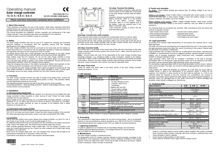
Operating manualSolar charge controller10.10 A / 8.8 A / 6.6 APlease read these instructions completely before installation!1. About this manualThese operating instructions are part of the product. Read these operating instructions carefully before use, keep them over the entire lifetime of the product, and pass them on to any future owner or user of this product.This manual describes the installation, function, operation and maintenance of the solar charge controller. These operating instructions are intended for end customers.A technical expert must be consulted in cases of uncertainty.2. SafetyThe solar charge controller may only be used in PV systems for charging and controlling lead-acid batteries in accordance with this operating manual and the charging specifications of the battery manufacturer.The solar charge controller may only be connected to the local loads and the battery by trained personnel and in accordance with the applicable regulations. Follow the installation and operating instructions for all components of the PV system.No energy source other than a solar generator may be connected to the solar charge controller. Follow the general and national safety and accident prevention regulations.Keep children away from PV systems. Do not use the solar charge controller in dusty environments, in the vicinity of solvents or where inflammable gases and vapours can occur. No open fires, flames or sparks in the vicinity of the batteries. Ensure that the room is adequately ventilated. Check the charging process regularly.Follow the charging instructions of the battery manufacturer. Battery Acid splashes on skin or clothing should be immediately rinse with plenty of water. Seek medical advice.Do not operate the solar charge controller when it does not appear to function at all. The solar charge controller or connected cables are visibly damaged or loose. In these cases immediately remove the solar charge controller from the solar modules and battery.3. FunctionsThe solar charge controller monitors the state of charge of the battery bank, controls the charging process, controls the connection/disconnection of loads. This optimises battery use and significantly extends its service life.The following protection functions are part of the basic function of the controller: Overcharge protection ; Deep discharge protection ; Battery undervoltage protection ; Solar module reverse current protection.4. Installation4.1 Mounting location requirementsDo not mount the solar charge controller outdoors or in wet rooms. Do not subject the solar charge controller to direct sunshine or other sources of heat. Protect the solar charge controller from dirt and moisture.Mount upright on the wall (concrete) on a non-flammable substrate. Maintain a minimum clearance of 10 cm below and around the device to ensure unhindered air circulation. Mount the solar charge controller as close as possible to the batteries (with a safety clearance of at least 30 cm).4.2 Fastening the solar charge controllerMark the position of the solar charge controller fastening holes on the wall.Drill 4 Ø 6 mm holes and insert dowels. Fasten the solar charge controller to the wall with the cable openings facing downwards, using 4 oval head screws M4x40 (DIN 7996).4.3 ConnectionUse an wire size suited to the current ratings of the charge controller, e.g. 6mm² for 10A, 5 mm² for 8A, 4 mm² for 6A, 3 mm² for 5A for cable length of 10 m.An additional external 20A fuse (not provided) must be connected to the battery connection cable, close to the battery pole. The external fuse prevents cable short circuits.Solar modules generate electricity under incident light. The full voltage is present, even when the incident light levels are low. Protect the solar modules from incident light during installation, e.g. cover them.Never touch not isolated cable ends. Use only insulated tools. Ensure that all loads to be connected are switched off. If necessary, remove the fuse.Connections must always be made in the sequence described below.1st step: Connect the batteryConnect the battery connection cable with thecorrect polarity to the middle pair of terminalson the solar charge controller (with the batterysymbol).If present, remove any external fuse. Connectbattery connection cable A+ to the positivepole of the battery. Connect batteryconnection cable A– to the negative pole ofthe battery. Insert the external fuse in thebattery connection cable.If the connection polarity is correct, the infoLED illuminates green.2nd step: Connect the solar moduleEnsure that the solar module is protected from incident light (cover it or wait for night).Ensure that the solar module does not exceed the maximum permissible input current.First connect the M+ solar module connection cable to the correct pole of the left pair ofterminals on the solar charge controller (with the solar module symbol), then connect theM– cable. Remove the covering from the solar module.3rd step: Connect loadsFirst connect the L+ load cable to the correct pole of the right pair of terminals on the solarcharge controller (with the lamp symbol), then connect the L– cable. Insert the load fuse orswitch on the load.Notes : Connect loads that must not be deactivated by the solar charge controller deepdischarge protection, e.g. emergency lights or radio connection, directly to the battery.Loads with a higher current consumption than the device output can be directly connectedto the battery. However, the solar charge controller deep discharge protection will no longerintervene. Loads connected in this manner must also be separately fused.4th step: Final workFasten all cables with strain relief in the direct vicinity of the solar charge controller(clearance of approx. 10 cm).5. LED displaysLED Status Meaningilluminates green normal operationInfo LEDflashes slowly red* system fault- too high charging current- overload / short circuit- overheatedtogether with red LED :- too low battery voltagetogether with green LED :- too high battery voltageflashing quickly* battery empty, low voltage disconnectionprewarning, loads still onBatteryredLED flashing slowly* deep discharge protection active (LVD), loadsdisconnectedilluminates battery weak, loads are onBatteryyellowLEDflashes slowly yellow* LVD reconnection setpoint has not yet beenreached, loads still disconnectedilluminates battery goodBatterygreenLEDflashes quickly green* battery full, charge regulation active*flashing slowly: 0,4Hz: 4 times in 10 second, flashing quickly: 3Hz: 3 times in 1 second6. GroundingThe components in stand-alone systems do not have to be grounded – this is not standardpractice or may be prohibited by national regulations (e.g.: DIN 57100 Part 410: Prohibitionof grounding protective low voltage circuits). Ask your dealer for technical assistance.7. Lightning protectionIn systems subjected to an increased risk of overvoltage damage, we recommendinstalling additional lightning protection / overvoltage protection to reduce dropouts.Ask your dealer for technical assistance.8. MaintenanceThe solar charge controller is maintenance-free.All components of the PV system must be checked at least annually, according to thespecifications of the respective manufacturers. Ensure adequate ventilation of the coolingelement. Check the cable strain relief. Check that all cable connections are secure. Tightenscrews if necessary. Check corrosion on terminals.9. Faults and remediesNo display : Check battery polarity and external fuse. Or battery voltage is too low orbattery defective.Battery is not charged : Check if solar modul is connected with correct polarity or if shortcircuit at the solar input. If solar module voltage is lower than battery voltage or if solarmodule is defective the battery cannot be charged.Battery displays jumps quickly : Battery voltage changes quickly. Large pulse currentscause voltage fluctuation. Battery is too small or defective. Ask your dealer for technicalassistance.The following faults do not destroy the controller. After correcting the fault, the device willcontinue to operate correctly:* solar module short circuits * reverse solar module polarity *2* short circuits at load output * excessive load current* reversed battery polarity *1* solar module overcurrent* device overtemperature * overvoltage at the load output10. Legal guaranteeAccording to the German legal requirements, for this product the customer has a 2 yearlegal guarantee.The seller will remove all manufacturing and material faults that occur in the product duringthe legal guarantee period and affect the correct functioning of the product. Natural wearand tear does not constitute a malfunction.Legal guarantee does not apply if the fault can be attributed to third parties, unprofessionalinstallation or commissioning, incorrect or negligent handling, improper transport, excessiveloading, use of improper equipment, faulty construction work, unsuitable constructionlocation or improper operation or use.Legal guarantee claims shall only be accepted if notification of the fault is providedimmediately after it is discovered. Legal guarantee claims are to be directed to the seller.The seller must be informed before legal guarantee claims are processed.For processing a legal guarantee claim an exact fault description and the invoice / deliverynote must be provided. The seller can choose to fulfil the legal guarantee either by repair orreplacement.If the product can neither be repaired nor replaced, or if this does not occur within asuitable period in spite of the specification of an extension period in writing by thecustomer, the reduction in value caused by the fault shall be replaced, or, if this is notsufficient taking the interests of the end customer into consideration, the contract iscancelled. Any further claims against the seller based on this legal guarantee obligation, inparticular claims for damages due to lost profit, loss-of-use or indirect damages areexcluded, unless liability is obligatory by German law.11. Technical DataSteca Solsum F 6.6F 8.8F 10.10FSystem voltage 12 V (24 V)Own consumption < 4 mADC input sideOpen circuit voltage solar module(at minimum operating temperature)< 47 VModule current 6 A 8 A 10 ADC output sideLoad current 6 A 8 A 10 AEnd of charge voltage 13.9 V (27.8 V)Boost charge voltage 14.4 V (28.8 V)Reconnection voltage (SOC / LVR) *³> 50 % / 12.4 V … 12.7 V(24.8 V … 25.4 V)Deep discharge protection (SOC / LVD) *³< 30 % / 11.2 V … 11.6 V(22.4 V … 23.2 V)Operating conditionsAmbient temperature -25 °C … +50 °CFitting and constructionTerminal (fine / single wire) 4 mm2 / 6 mm2 - AWG 12 / 9Degree of protection IP 32Dimensions (X x Y x Z) 145 x 100 x 24 mmWeight approx. 150 g*1Solsum is protected against reverse battery polarity together with polarity protectedloads. Reverse battery polarity combined with short circuited or polarised load couldcause damages in load or regulator*2Avoid reverse module polarity in a 24V system*3Lower value for nominal current, higher value for lowest currentInfo LED Battery LEDsManufactured in aDIN EN ISO 9001:2000 facilitySolsum / Z02 / Version 1104/ 730.930。
太阳能充电控制器操作手册 10.10 A 8.8 A 6.6 A说明书

Operating manualSolar charge controller10.10 A / 8.8 A / 6.6 APlease read these instructions completely before installation!1. About this manualThese operating instructions are part of the product. Read these operating instructions carefully before use, keep them over the entire lifetime of the product, and pass them on to any future owner or user of this product.This manual describes the installation, function, operation and maintenance of the solar charge controller. These operating instructions are intended for end customers.A technical expert must be consulted in cases of uncertainty.2. SafetyThe solar charge controller may only be used in PV systems for charging and controlling lead-acid batteries in accordance with this operating manual and the charging specifications of the battery manufacturer.The solar charge controller may only be connected to the local loads and the battery by trained personnel and in accordance with the applicable regulations. Follow the installation and operating instructions for all components of the PV system.No energy source other than a solar generator may be connected to the solar charge controller. Follow the general and national safety and accident prevention regulations.Keep children away from PV systems. Do not use the solar charge controller in dusty environments, in the vicinity of solvents or where inflammable gases and vapours can occur. No open fires, flames or sparks in the vicinity of the batteries. Ensure that the room is adequately ventilated. Check the charging process regularly.Follow the charging instructions of the battery manufacturer. Battery Acid splashes on skin or clothing should be immediately rinse with plenty of water. Seek medical advice.Do not operate the solar charge controller when it does not appear to function at all. The solar charge controller or connected cables are visibly damaged or loose. In these cases immediately remove the solar charge controller from the solar modules and battery.3. FunctionsThe solar charge controller monitors the state of charge of the battery bank, controls the charging process, controls the connection/disconnection of loads. This optimises battery use and significantly extends its service life.The following protection functions are part of the basic function of the controller: Overcharge protection ; Deep discharge protection ; Battery undervoltage protection ; Solar module reverse current protection.4. Installation4.1 Mounting location requirementsDo not mount the solar charge controller outdoors or in wet rooms. Do not subject the solar charge controller to direct sunshine or other sources of heat. Protect the solar charge controller from dirt and moisture.Mount upright on the wall (concrete) on a non-flammable substrate. Maintain a minimum clearance of 10 cm below and around the device to ensure unhindered air circulation. Mount the solar charge controller as close as possible to the batteries (with a safety clearance of at least 30 cm).4.2 Fastening the solar charge controllerMark the position of the solar charge controller fastening holes on the wall.Drill 4 Ø 6 mm holes and insert dowels. Fasten the solar charge controller to the wall with the cable openings facing downwards, using 4 oval head screws M4x40 (DIN 7996).4.3 ConnectionUse an wire size suited to the current ratings of the charge controller, e.g. 6mm² for 10A, 5 mm² for 8A, 4 mm² for 6A, 3 mm² for 5A for cable length of 10 m.An additional external 20A fuse (not provided) must be connected to the battery connection cable, close to the battery pole. The external fuse prevents cable short circuits.Solar modules generate electricity under incident light. The full voltage is present, even when the incident light levels are low. Protect the solar modules from incident light during installation, e.g. cover them.Never touch not isolated cable ends. Use only insulated tools. Ensure that all loads to be connected are switched off. If necessary, remove the fuse.Connections must always be made in the sequence described below.1st step: Connect the batteryInfo LED Battery LEDsConnect the battery connection cable with thecorrect polarity to the middle pair of terminalson the solar charge controller (with the batterysymbol).If present, remove any external fuse. Connectbattery connection cable A+ to the positivepole of the battery. Connect batteryconnection cable A– to the negative pole ofthe battery. Insert the external fuse in thebattery connection cable.If the connection polarity is correct, the infoLED illuminates green.2nd step: Connect the solar moduleEnsure that the solar module is protected from incident light (cover it or wait for night).Ensure that the solar module does not exceed the maximum permissible input current.First connect the M+ solar module connection cable to the correct pole of the left pair ofterminals on the solar charge controller (with the solar module symbol), then connect theM– cable. Remove the covering from the solar module.3rd step: Connect loadsFirst connect the L+ load cable to the correct pole of the right pair of terminals on the solarcharge controller (with the lamp symbol), then connect the L– cable. Insert the load fuse orswitch on the load.Notes : Connect loads that must not be deactivated by the solar charge controller deepdischarge protection, e.g. emergency lights or radio connection, directly to the battery.Loads with a higher current consumption than the device output can be directly connectedto the battery. However, the solar charge controller deep discharge protection will no longerintervene. Loads connected in this manner must also be separately fused.4th step: Final workFasten all cables with strain relief in the direct vicinity of the solar charge controller(clearance of approx. 10 cm).5. LED displaysLED Status Meaningilluminates green normal operationInfo LEDflashes slowly red* system fault- too high charging current- overload / short circuit- overheatedtogether with red LED :- too low battery voltagetogether with green LED :- too high battery voltageflashing quickly* battery empty, low voltage disconnectionprewarning, loads still onBatteryredLED flashing slowly* deep discharge protection active (LVD), loadsdisconnectedilluminates battery weak, loads are onBatteryyellowLEDflashes slowly yellow* LVD reconnection setpoint has not yet beenreached, loads still disconnectedilluminates battery goodBatterygreenLEDflashes slowly green* battery full, charge regulation active*flashing slowly: 0,4Hz: 4 times in 10 second, flashing quickly: 3Hz: 3 times in 1 second6. GroundingThe components in stand-alone systems do not have to be grounded – this is not standardpractice or may be prohibited by national regulations (e.g.: DIN 57100 Part 410: Prohibitionof grounding protective low voltage circuits). Ask your dealer for technical assistance.7. Lightning protectionIn systems subjected to an increased risk of overvoltage damage, we recommendinstalling additional lightning protection / overvoltage protection to reduce dropouts.Ask your dealer for technical assistance.8. MaintenanceThe solar charge controller is maintenance-free.All components of the PV system must be checked at least annually, according to thespecifications of the respective manufacturers. Ensure adequate ventilation of the coolingelement. Check the cable strain relief. Check that all cable connections are secure. Tightenscrews if necessary. Check corrosion on terminals.9. Faults and remediesNo display : Check battery polarity and external fuse. Or battery voltage is too low orbattery defective.Battery is not charged : Check if solar modul is connected with correct polarity or if shortcircuit at the solar input. If solar module voltage is lower than battery voltage or if solarmodule is defective the battery cannot be charged.Battery displays jumps quickly : Battery voltage changes quickly. Large pulse currentscause voltage fluctuation. Battery is too small or defective. Ask your dealer for technicalassistance.The following faults do not destroy the controller. After correcting the fault, the device willcontinue to operate correctly:* solar module short circuits * reverse solar module polarity *2* short circuits at load output * excessive load current* reversed battery polarity *1* solar module overcurrent* device overtemperature * overvoltage at the load output10. Legal guaranteeAccording to the German legal requirements, for this product the customer has a 2 yearlegal guarantee.The seller will remove all manufacturing and material faults that occur in the product duringthe legal guarantee period and affect the correct functioning of the product. Natural wearand tear does not constitute a malfunction.Legal guarantee does not apply if the fault can be attributed to third parties, unprofessionalinstallation or commissioning, incorrect or negligent handling, improper transport, excessiveloading, use of improper equipment, faulty construction work, unsuitable constructionlocation or improper operation or use.Legal guarantee claims shall only be accepted if notification of the fault is providedimmediately after it is discovered. Legal guarantee claims are to be directed to the seller.The seller must be informed before legal guarantee claims are processed.For processing a legal guarantee claim an exact fault description and the invoice / deliverynote must be provided. The seller can choose to fulfil the legal guarantee either by repair orreplacement.If the product can neither be repaired nor replaced, or if this does not occur within asuitable period in spite of the specification of an extension period in writing by thecustomer, the reduction in value caused by the fault shall be replaced, or, if this is notsufficient taking the interests of the end customer into consideration, the contract iscancelled. Any further claims against the seller based on this legal guarantee obligation, inparticular claims for damages due to lost profit, loss-of-use or indirect damages areexcluded, unless liability is obligatory by German law.11. Technical DataSteca Solsum F 6.6F 8.8F 10.10FSystem voltage 12 V (24 V)Own consumption < 4 mADC input sideOpen circuit voltage solar module(at minimum operating temperature)< 47 VModule current 6 A 8 A 10 ADC output sideLoad current 6 A 8 A 10 AEnd of charge voltage 13.9 V (27.8 V)Boost charge voltage 14.4 V (28.8 V)Reconnection voltage (SOC / LVR) *³> 50 % / 12.4 V … 12.7 V(24.8 V … 25.4 V)Deep discharge protection (SOC / LVD) *³< 30 % / 11.2 V … 11.6 V(22.4 V … 23.2 V)Operating conditionsAmbient temperature -25 °C … +50 °CFitting and constructionTerminal (fine / single wire) 4 mm2 / 6 mm2 - AWG 12 / 9Degree of protection IP 32Dimensions (X x Y x Z) 145 x 100 x 24 mmWeight approx. 150 g*1Solsum is protected against reverse battery polarity together with polarity protectedloads. Reverse battery polarity combined with short circuited or polarised load couldcause damages in load or regulator*2avoid reverse module polarity in a 24V system*3Lower value for nominal current, higher value for lowest currenManufactured in aDIN EN ISO 9001:2000 facilitySolsum / Z02 / Version 09.45/ 730.930。
太阳能智能充电控制器使用说明书
问题及处理方法 请检查光电池连线是否正确,接触是否可靠 系统超压,请检查蓄电池是否连接可靠,或是蓄电池电压过高; 蓄电池供电故障,请检测蓄电池连接是否正确 蓄电池过放,充足后自动恢复 负载功率超过额定功率,减少用电设备后,长按键一次恢复 负载短路,故障排除后,长按键一次或第二天自动恢复 请检查用电设备是否连接正确、可靠 请检查外接电源是否连接正确,+,-极有无接反,电源有无供电 检测接线是否可靠,12V/24V 自动识别是否正确(针对自动识别的型号)
保护电路:
E 系列 □5A □10A □15A □20A □5A □10A □15A □20A □12V ; □24V ; □12V/24V Auto
<5mA; 不大于 0.20V; 不大于 0.20V; 17V;×2/24V; 14.6V;×2/24V (维持时间:30min)(当出现过放电时调用,或每 7 天调用一次) 14.4V;×2/24V (维持时间:30min) 13.6V;×2/24V (维持时间:直至降到充电返回电压动作) 13.2V;×2/24V 12.5V;×2/24V 12.0V;×2/24V 11.5V; ×2/24V 11.1V;×2/24V 12.0V;×2/24V 4mv/℃/2V(提升、直充、浮充、充电返回电压补偿); 充电:PWM 脉宽调制; -35℃至+65℃; 1.25 倍额定电流 30 秒;1.5 倍额定电流 5 秒过载保护动作;≥3 倍额定电流短路保护。
solar power intelligent PV controller
Instruction book
Main features
1.
Intelligent control is realized by using microprocessor and dedicated control calculation.
PWM 12 24V 30A 太阳能充电控制器说明书

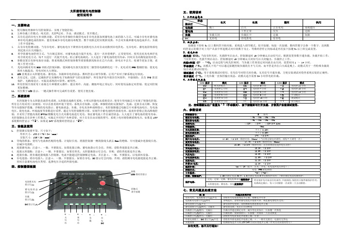
Solar Charge ControllerThis device is a PWM 12/24V 30A charge controller used in solar applications. Its flush mount design is ideal for solar power systems in RV's, boats and vehicles. Carefully read the manual before installation.l)PCBA common negative design, necessary for all negative grounded solar power systems.2) 12/24V auto recognition. Lithium battery must be set manually set. 3)PWM 3-phase charging: equalize - boost- float (for Flooded, AGM and GEL). 4) Easy to use settings. User defined parameters for lithium battery.SJ F lush mount design for convenient installation.6)Back lit LCD display (system status, current, voltage, voltage value settings, etc).7) Easy to use menu buttons.8) SV USB port for mobile device charging.9) Temperature compensation for better battery maintenance in extreme environments.lO) Multiple built in protections including solar reverse connection, battery reverse connection, battery over-discharge and over voltage.1) IMPORTANT REMINDERS•The battery must be connected to the controller first.•Please note that the maximum solar (PV) input voltage is SSV open circuit voltage (OCV). Do not use solar panel(s) with working voltage (VMP) of more than 40V (refer to solar (PV) module specs).•Note the maximum solar (PV) input power is 450W/12V or 900W/24V. Do not exceed the rated power.•Do not change any settings in the "LI" battery mode if you are not using a lithium battery.•In the LI battery mode, you must set the battery system voltage (12 or 24V) manually. SET THE VOLTAGE FIRST, then set the charging voltage.•If you would like to check the information in the "Li" battery mode settings, but not alter any settings, remember to set the correct voltage set (12 or 24V) before exiting from the settings.2)HARDWARE SUGGESTIONS*For maximum PWM charge efficiency, we suggest using solar panels with an output of 18V (VMP) for a 12V battery system, and 36V (VMP) panel for 24V battery systems. You can still use panels with lower voltages but it may lead to a slightly lower charge efficiency. In all cases the solar (PV) input voltage (VMP) must be higher than the battery system voltage.*For added safety and protection we suggest using a DC breaker or fuse between both the solar panel and the controller, as well as between the controller and the battery.5 61 LCD Display 5 Solar input wiring terminal2 USB Port 6Battery wiring terminal 3 Set/Page button 7Installation holes4Parameter set button•First: Connect the battery first.Last: Connect the solar panel second, use 10AWG PV wire.1) Display OverviewYou can check system information using the LCD display, including PV input voltage, charge current, battery voltage, battery capacity, controller temperature, error code and battery setting pages.��ram.�=��:Error�ii:;e Settingr ----------------------------�-.&.12V 24V 0:��:; 0 ·� ·� 0 V%°C!ICHG_Vu u.u.uA kWh:,-.�•PV Charge StatusStatusBattery Status2) Solar (PV), Battery & Charge Indications ICONITEMON PVOFF $ IndicationSlow flash ON Fast flash ONiiiON Battery Indication Fast flash ON � ChargeFlowing IndicationNo flowINDICATION REMARKPV volt higher than light control volt PV volt lower than light control volt Charging PV over voltage Battery is ok Battery is not ok Battery over discharged ChargingNo chargeUs er 's M an u alS TAT US OFFl)Button Setting InfoThere are 2 buttons on the controller for operations and settings. Check the below diagram for setting details:BUTTONSETTING STATUSPRESSFUNCTIONIn Setting «Not in Setting In Setting (+/-)Not in SettingP ress & hold Enter pageQ uickly pr e ss Enter next page for settings P ress & hold Enter page for settings Q uickly pr e ss Enter next page P ress & hold No function Q uickly press To adjust parameter P ress & hold No function Q uickly press No functionRemarks: "In Setting" means the user is in process of setting parameters.2) Information Pages::---L 1 • -: . f :Mn1Type���·--�-■---8 -• Syst.emVolt.ilgeI121I SettingI•�•�-�----,: �:��1��� � •ChargeVottageI.._,IYY' �'--"------,..,...,....., ..lb�•-rTyJ>O<;ott;ogl1) Battery Type Setting•• • DISPLAYFLD SEL GELLIFLd:��-----: =?SEL•I L:.ea$. :I ___________ �¢==ij • 'E' U L:.ea$. : :.ea$. :! ___________ �! ___________ �BATTERY TYPE REMARKSFlooded Battery Sealed/AGM Battery Gel Battery Lithium BatteryBattery system voltage auto recognition; parameters set.System voltage, charge/discharge parameters, adjustable.2) Battery System Voltage Setting (only for lithium battery , set manually)•V3) Charge Voltage Setting (only for lithium battery)CIILY,uuvf I. I·�•The controlle r may display an error code on the LCD screen if there is an issue in the system. If this happens please refer to the below diagram:CODE ERRORANALYSIS SOLUTION (Recovery)EOONo Error--Recovered once batteryThe battery has beenvoltage returns to normalEOl Over-dischargeddischarged belowrange. An alternate charge normal ranges.source may be requireddepending on depth of discharge The battery voltage Recovered after the battery voltage returns to the normal E02 Over voltageexceeds the normal range. It is possible that the range.battery m ay be defective. Charge shuts downRecovered after temperature E06 Device over heatingdue to high temperature returns to the normal range. inside the controller The solar (PV) input Recovered after the solar (PV) EOB Input over load power exceeds the input power is within the rated value controller ratings.The solar (PV) input Recovered after the solar (PV) ElOPV over voltage input voltage is within the voltage is too high. controller ratings. EBPV anti-connection Solar (PV) module +-Correct the + and -solar polarity reverse-connection connection.E14Battery anti-connectionBattery+-polarity Correct the + and -battery reverse-connectionconnection.ITEMPARAMETERSModel No. SCC30AFMSystem Voltage12V/24V No-load Loss8ma (12V) , 12ma (24V)Max PV Input Voltage< 55Voc Rated Charge Current 30AMax PV Input Power 450W/12V; 900W/24VBattery Type Selection FLD SEL GEL LI Equalize Charge Voltage14.8V (12V) / 14.6V (12V) / --29.6V (24V) 29.2V (24V)14.6V (12V) / 14.4V (12V) / 14.2V (12V) / 14.2V (12V) / Boost Charge Voltage28.2V (24V)29.2V (24V)28.BV (24V) 28.4V (24V)adjustableFloat Charge Voltage 13.8V (12V) / 27.6V (24V) -Boost Charge Recovery Volt13.2V (12V) / 26.4V (24V)-11.0V (12V) /Over Discharge 21.0V (24V )Recovery Volt.12.6V (12V) / 25.2V (24V)*auto adjusted to over-discharge volt10.0V (12V) /Over Discharge Voltage 11.1 V (12V) / 22.2V(24V)20.0V (24V) adjustableLight Control VoltageSV(l2V system) , 10V(24V system)Light Control Delay Time 10s Operation Temperature-35"C -+45"CIP ProtectionIP32 Net Weight1 lbController Size6.67" x 5.12" x 1.84"。
- 1、下载文档前请自行甄别文档内容的完整性,平台不提供额外的编辑、内容补充、找答案等附加服务。
- 2、"仅部分预览"的文档,不可在线预览部分如存在完整性等问题,可反馈申请退款(可完整预览的文档不适用该条件!)。
- 3、如文档侵犯您的权益,请联系客服反馈,我们会尽快为您处理(人工客服工作时间:9:00-18:30)。
太阳能电动车充电控制器使用说明
一、概述
CJCD系列太阳能电动车充电控制器安装在电动车上,能够将太阳能电池板输出的直流电,通过控制器内部调压装置,调节出充足的电能供蓄电池充电,即可实现电动车边走边充,大大提高蓄电池的使用寿命,最大解决了电动车行程短的难题。
本控制器也适用于离网光伏发电系统。
二、产品特点
1、采用先进CPU精确计算,大大提高充电效率,节约电池板能量,减轻电池板成本。
2、高速高性能芯片及合理设计,使控制器反应速度快,工作稳定。
3、输入电压宽(DC12-45V),适合10-400瓦太阳能光伏组件。
4、输出电压宽,满足多种电动车,48V、60V、72V自由调整。
5、LED数码管直观的显示太阳能充电电压。
6、控制器从太阳能电池板取电,不消耗蓄电池能量,待机功耗为零。
7、内置保险丝,具有过流、短路保护。
三、技术参数
1、本控制器专为太阳能电池板升压设计,用于太阳能电动车充电、离网光伏发电系统。
2、控制器输入端只能接入12V---45V的太阳能电池板,电池板功率10-400W。
3、控制器输入端接线:红线接正极,蓝线接负极,千万不可接反。
4、控制器输出端接电动车电瓶,适应于48V、60V、72V的电瓶,输出电压通过开关调。
拨动开关48V位置---------空载显示56V±2V(可充48V蓄电池)
拨动开关60V位置---------空载显示72V±2V(可充60V蓄电池)
拨动开关72V位置---------空载显示82V±2V(可充72V蓄电池)
5、控制器输出端接线:红线接正极,蓝线接负极,千万不可接反。
6、
1、控制器输入端只能接光伏板组件,千万不能接其他电源、电动车电瓶及空载接超过45V
的太阳能组件,切记!切记!切记!
2、输出端的电压一定要和电动车电瓶的电压匹配,不匹配,千万不要接!。