API682标准冲洗方案.
API682:2004机械密封辅助系统介绍

机械密封辅助系统介绍API 682:2004yoyo_i整理API 682:2004美国石油协会技术标准:离心旋转泵用轴封系统的附录G编入的是已经应用在工业上的标准冲洗布置和辅助硬件的图纸。
虽然API 682:2004未引入这类布置图纸的全部,但经过买方的同意,他们可以用于特殊情况。
API682 2004:冲洗方案01a)管道和仪表流程图b)密封腔细部图图注:1、进口2、急冷接口/排液接口(Q/D)3、密封腔从泵的出口到密封的完整循环过程,只推荐应用洁净的工作介质。
方案01 :除了冲洗液冲叶轮后部靠近出口的部位直接引入密封腔以外,方案01与方案11非常相似。
这种冲洗方案仅适用清洁流体。
冲洗方案 1 常用于常温下,且被输送流体非常粘稠或容易固化的情况下,以防止流体在冲洗管内凝固。
对于方案1,要特别注意再循环量的供应要充分满足密封操作条件。
a)管道和仪表流程图b)密封腔细部图图注:1、备日后接循环液体用的堵头接口2、放气口(如果需要)3、加热/冷却进口(HI或CL),加热/冷却出口(HO/CO)4、冲洗口/排液口(Q/D)5、密封腔卧式泵优先采用放气布置。
方案02 :用于无冲洗流体循环,密封腔一端封闭的情况下,一般用于化工行业中的密封腔压力和温度较低的情况下。
通常,这种冲洗方案采用锥形密封腔以改进流体的流动形式。
这种方案通常用于被输送的介质比较清洁,以防止由于旋涡的作用对密封法兰盘、密封腔或密封部件产生侵蚀作用。
同时也要考虑被密封介质的闪蒸敏感性以避免在密封腔中或密封端面产生闪蒸。
这种冲洗方案也可以用于温度较低的、清洁的、比热较高的流体(水),且泵的转速一般不高。
当采用方案02时,要仔细计算输送介质汽化的温度裕量。
a)管道和仪表流程图b)密封腔细部图图注:1、来自泵的出口2、冲洗接口(F)3、急冷接口/排液口(Q/D)4、密封腔从泵的出口通过限流孔板道密封的循环过程。
冲洗液进入密封腔靠近机械密封端面处冲洗端面,然后穿过密封腔回流到泵。
第三版API682标准冲洗方案Plan53解析
1 引言
第三版 A I6 2 心泵 、 P 8 离 转子泵用轴 封系统(hf S ̄ n S a e ig t
Ss msf etfgla d R t yP m s yt o C nru a n o r u p) e r i a 是美 国石油协会发
1
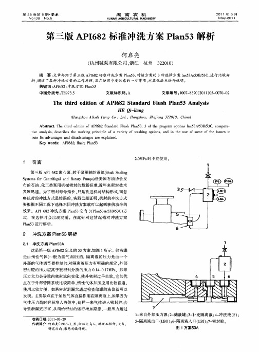
这是第一版 A I8 P6 2定义 的 5 方案 , 3 如图 1 示。储液罐 所 是 由惰性气 体( 一般 为氮气)Ⅱ 的,隔离 液 的压 力是 由一个 力压
外部 的气体 调节器控制 的, 对隔离液压力 有 明确 的规定 , 外部
密封腔 的压力 应高于被密封介质 的压力 O1 ~ .7 a . 01MP ,如果 4 压力 太力会导致 内密封 流向变化 , 使外 密封过早 失效 。 的优 它 点在 于外部管路 系统比较简单 , 惰性气 体加压应用 比较普 遍 , 使用 比较 方便 ,如果密 封泄 漏大通过检查储 罐的液位就可 以 发 现。主要缺 点在 于加压气 体直接作 用在隔离液上, 因为 如果
气体 压力高时容易溶入 液体中 , 样一来气体 进入密封 腔, 这 会
导致泄漏更厉 害 , 而给密封 的运行增 加隐患 , 般压力超过 从 一 1 来 自外部压力 源 ;一 一 2 储液罐 ;- 3 补充隔离 液 ;一 4 冲洗液 ( ) F;
收 稿 日期 :0 10 — 9 2 1- 3 2
Th h r d to f API 8 t n a d Fl h a 5 e t i d e ii n o 6 2 S a d r us Pl n 3 Anay i l ss HE Q -in il g a
( nzo k iP m o,Ld,H nzo , hj n 2 0 0 hn) Hagh uAld u p C . t . a gh u Z ei g3 2 1 ,C i a a
机械密封冲洗方案

—
两对密封端面之间的压力
低于密封腔压力
密封腔的压力应高于大气压力0.035MPa
a)密封腔的压力-介质饱和蒸汽压 ≥0.35MPa。 b)密封腔的压力(绝压)/介质饱和蒸汽 压≥1.3 宜满足a),若a)达不到,应满足b)
布置方式3 两对密封端面(双端面)
隔离液由外部引入到两对密封端 面间,其压力高于密封腔压力。
方案描述:通过密封 腔的结构设计实现冲 洗液的循环。
特点:密封腔为圆锥 形,无喉部衬套。
用于密封产生热量不多的场合; 用于传统密封腔会产生固体颗粒聚集的场合。
Plan11
用于泵送清洁流体的场合。
方案描述:从泵出口 经限流孔板流到密封 腔。
Plan12
方案描述:从泵出口 经过滤器和限流孔板 流到密封腔。
单端面
F-冲洗口 Q-急冷(吹扫)口 D-排净口
双端面
背对背
面对背
面对面
LBI/LBO-缓冲液(隔离液)入口/出口
密封端面材料
密封面材料 碳化钨 碳化硅(无压烧结) 碳化硅(反应烧结) 加碳碳化硅(无压烧结) 加碳碳化硅(反应烧结) 碳石墨:
浸渍树脂 浸渍锑
最高温度℃ 1100 1650 1400 550 550
285 500
一、API682的由来 二、机械密封的结构 三、机械密封的分类 四、机械密封冲洗方案
► 三个系列:系列1、系列2、系列3 ► 三种型式:A型、 B型、 C型 ► 三种布置方式: 布置方式1、 2、 3
三个系列
特征 密封腔尺寸标准
密封腔温度范围 最大密封腔压力 是否提供双端面密封内循环 装置的流量-扬程曲线 订单资料要求 合同资料要求
Plan01
用于泵送清洁流体的场合; 用于常温下较粘稠或易固化的流体。
API682(第三版)密封标准冲洗方案的解释70461789
2020/9/6
28
API682:2004/标准冲洗布置和辅助硬件图 PLAN53b
2020/9/6
29
API682:2004/标准冲洗布置和辅助硬件图 PLAN53cAPI682:2004/标准冲洗布置和辅助硬件图 PLAN53c
2020/9/6
31
API682:2004/标准冲洗布置和辅助硬件图 PLAN53a,b,c
2020/9/6
32
API682:2004/标准冲洗布置和辅助硬件图 PLAN53a,b,c
2020/9/6
33
API682:2004/标准冲洗布置和辅助硬件图 PLAN54
2020/9/6
34
API682:2004/标准冲洗布置和辅助硬件图 PLAN54
2020/9/6
35
API682:2004/标准冲洗布置和辅助硬件图 PLAN54
ANSI API682:2004/ISO21049:2004
(第三版)
工程技术部----
2020/9/6
1
API682:2004/标准冲洗布置和辅助硬件图 PLAN01
2020/9/6
2
API682:2004/标准冲洗布置和辅助硬件图 PLAN01
2020/9/6
3
API682:2004/标准冲洗布置和辅助硬件图 PLAN02
2020/9/6
20
API682:2004/标准冲洗布置和辅助硬件图 PLAN41
2020/9/6
21
API682:2004/标准冲洗布置和辅助硬件图 PLAN51
2020/9/6
22
API682:2004/标准冲洗布置和辅助硬件图 PLAN52
API682 方案53详细说明
API682 方案53详细说明方案53或布置方式3(加压双端面密封)用于不允许输送介质泄露到大气中的情况。
方案53a由双端面密封和密封之间的阻封液构成。
阻封液盛装一个密封罐中,密封罐的压力高于被密封介质压力0.14MPa。
内部密封泄露时,阻封液泄到被输送的介质中。
如果被密封介质压力变化过大,或高于500psig,外部密封腔压力可以通过应用可控压差调节器,以设定外部密封腔压力高于被密封介质压力0.14MPa~0.17MPa。
方案53b也是一种加压双端面密封,与53a的差别是方案53b通过过袋式缓冲器维持密封循环系统的压力。
方案53c也是一种加压双端面密封,但它采用活塞式缓冲器维持阻封系统压力高于被密封介质压力。
方案53通常用于代替52,用于脏的、磨蚀的、或聚合性介质,在这些情况下如果采用方案52要么会损坏密封要么会引起阻封系统出现问题。
方案53有两个缺点在选择时需要考虑。
首先,采用方案53时,阻封液总会泄到被输送的介质中去(泄露率可以通过密封罐的液位来监测),所以产品中总会包含一定量从阻封系统中的杂质。
其次,方案53系统依靠密封罐中的压力维持在正确的数量。
如果密封罐压力下降,系统就会像方案52或像无压双端面密封一样操作,这时所提供的密封性能与方案53将会不同。
尤其是内部密封的泄露方向发生相反方向的变化,阻封液中就会含有产品杂质,从而可能会导致其他密封失效。
acidity, mL.; M--calibration of the molar concentration of sodium hydroxide standard solution, moI/L; V--amount of the volume of sodium hydroxide standard solution, Ml; M--the weight of the sample, g. Such as poor meets the requirements, take the arithmetic mean of the second determination as aresult. Results one decimal. 6, allowing differential analyst simultaneously or in quick succession for the second determination, the absolute value of the difference of the results. This value should be no more than 1.0. 1, definitions and principles for determination of ash in starches, starch and ash: starch samples of ash the residue obtainedafter weight. Original sample residue weight of sample weight or weight expressed as a percentage of the dry weight of the sample. Samples ofash at 900 ? high temperature until ashing sample ... The Crucible: determination of Platinum or other conditions of the affected material, capacity of 50mL. Dryer: has effectively adequate drying agent and-perforated metal plate or porcelain. Ashing furnaces: device for controlling and regulating temperature, offers 900 incineration temperature of 25 c. Analytical balance. Electric hot plate or Bunsen. 3, crucible of analysis steps preparation: Crucible must first wash with boiling dilute hydrochloric acid, then wash with a lot of water and then rinse with distilled water. Wash the Crucible within ashing furnace, heated at 900 to 25 ? 30min, and in the desiccator to cool to room temperature and then weighing,方案53a管道和仪表流程图acidity, mL.; M--calibration of the molar concentration of sodium hydroxide standard solution, moI/L; V--amount of the volume of sodium hydroxide standard solution, Ml; M--the weight of the sample, g. Such as poor meets the requirements, take the arithmetic mean of the seconddetermination as a result. Results one decimal. 6, allowing differential analyst simultaneously or in quick succession for the second determination, the absolute value of the difference of the results. This value should be no more than 1.0. 1, definitions and principles for determination of ash in starches, starch and ash: starch samples of ash the residue obtained after weight. Original sample residue weight of sample weight or weight expressed as a percentage of the dry weight of the sample. Samples of ash at 900 ? high temperature until ashing sample ... The Crucible: determination of Platinum or other conditions of the affected material, capacity of 50mL. Dryer: has effectively adequate drying agent and-perforated metal plate or porcelain. Ashing furnaces: device for controlling and regulating temperature, offers 900 incineration temperature of 25 c. Analytical balance. Electric hot plate or Bunsen. 3, crucible of analysis steps preparation: Crucible mustfirst wash with boiling dilute hydrochloric acid, then wash with a lot of water and then rinse with distilled water. Wash the Crucible within ashing furnace, heated at 900 to 25 ? 30min, and in the desiccator to cool to room temperature and then weighing,密封腔细部图图注:1、来自外部压力源2、储液罐3、补充隔离液4、冲洗液(F)5、隔离液出口(LBO)6、隔离液入口(LBI)7、密封腔LSH 液位开关高位LSL 液位开关低位LI 液位计PI 压力计PSL 压力开关低位外设加压隔离液储罐提供洁净的液体给密封腔。
密封冲洗方案

机械密封冲洗方案净化分厂李志2009年11月17日一、API682 简介密封冲洗类型三、现场冲洗方案四、屏蔽泵一、API682 简介美国石油学会标准离心泵及回转泵轴封系统Shaft Sealing Systems forCentrifugal and Rotary PumpsAPI682是美国石油协会1994年10月发布的石油、化1.概述工类泵用机械密封的最新标准。
近年来密封技术发展很快。
集装式机械密封不及新材料的不断应用,使密封寿命大大延长,泄漏大减少。
API682标准充分反映了密封技术的这种发用户得益于这些发展。
API682不但能被符合API610的离心泵或符合的转子泵所引用,而且也能被其它转动设备所引用。
2.API682的章节及编制目的API 682标准包含以下章节:1.总则(General);(Seal Design);辅助设备(Accessories);测试设备/仪表(Instruments);检验、测试和发货前的准备(Inspection, test,and preparation for shipment);制造厂数据(Manufacturers data)。
附录制定API 682标准的目的是:2.API682的章节及编制目的(1)在满足环保机构对泄漏量规定的条件下,要求机械密封连续运转周期最少3年;)精简密封种类,提供一套选择方案的密封选型程序,以保证选用密封的可靠,低库存及维修费用。
为了达到这个目的,必须选用合适的密封型式和配置,合适的密封系统和材料,并遵循严格的试验规范。
3.API682的密封型式和配置(1)所有的标准型机械密封均应为集装式设计)标准型机械密封型式)密封配置a.单端面密封b.无压双重密封相当于串联密封c.有压双重密封相当于双端面机械密封3.API682的密封型式和配置标准型机械密封型式①滑动式多弹簧密封其配对密封面为烧结碳化硅对优质浸渍石合成橡胶,弹簧为哈氏合金C,其如轴套、压盖、限位器等)为316不锈压盖内需设置一个优质石墨制成的节流衬环。
国外公司的机封冲洗方案(满足API682标准)
Mechanical Seal Piping PlansSingle Seals plans 01, 02, 11, 13, 14, 21, 23, 31, 32, 41Dual Seals plans 52, 53A, 53B, 53C, 54Quench Seals plans 62, 65Gas Seals plans 72, 74, 75, 76Flow SolutionsMechanical Seal Piping Plans Flowserve’s Flow Solutions Division recognizes one of the most effective ways to achieve long, uninterrupted mechanical seal life is to create a healthy environment around the seal faces. Piping plans help keep mechanical seals running cool and clean, promote safe handling of dangerous fluids, and extend the operational availability of rotating equipment. This reference book provides a concise summary of the most essential piping plans used successfully in today’s process plants.Each plan shows all the standard and optional auxiliary components referenced in ISO 21049 / API Standard 682 and recommended by Flowserve. Consult your local Flowserve Flow Solutions Sales Engineer to identify the right solution that satisfies your application requirements.•Simplified centrifugal pump shown for all plans •Shows typical sealarrangements•Provides general tips toimprove reliability and fortroubleshootingPage LayoutWhatInternal seal chamber flush from pump discharge.Operates similar to Plan 11.WhySeal chamber heat removal.Seal chamber venting on horizontal pumps.Reduce risk of freezing/polymerizing fluid in exposed Plan 11 piping.WhereCustom seal chamber, most likely an ANSI/ASME pump.Clean, moderate temperature fluids.Used with single seals, rarely with dual seals.Preventative MaintenanceFlush typically can not be directed over seal faces and seal heat removal is limited.Calculate flush flow rate based on head loss through internal porting.WhatDead-ended seal chamber with no flush.WhyNo fluid recirculation needed.WhereLarge bore/open throat seal chambers in moderate temperature services.Cooling jacket seal chambers in high temperature services.Clean fluids.Top-entry mixers/agitators with dry seals.Preventative MaintenanceProcess must have adequate boiling point margin to avoid vaporization.Cooling fluid in seal chamber jacket may be needed at all times in hot services. Horizontal equipment must be self-venting.Often used in combination with steam quench, Plan 62.WhatSeal flush from pump discharge through orifice.Default single seal flush plan.WhySeal chamber heat removal.Seal chamber venting on horizontal pumps.Increase seal chamber pressure and fluid vapor margin.WhereGeneral applications with clean fluids.Clean, non-polymerizing fluids.Preventative MaintenanceUse an orifice with a minimum 0.125" (3 mm) diameter.Calculate flow rates to size orifice for adequate seal chamber flow.Increase boiling point margin with proper orifice and throat bushing sizing.Flush should be directed over seal faces with piping at 12 O’clock position.Typical failure mode is a clogged orifice - check temperatures at pipe ends.WhatRecirculation from seal chamber to pump suction through orifice.Standard flush plan on vertical pumps.WhyContinuous seal chamber venting on vertical pumps.Seal chamber heat removal.WhereVertical pumps.Seal chamber pressure is greater than suction pressure.Moderate temperature fluids with moderate solids.Non-polymerizing fluids.Preventative MaintenanceVent piping loop prior to starting vertical pumps.Use an orifice with a minimum 0.125" (3 mm) diameter.Calculate flow rates to size orifice for adequate seal chamber flow.Reduce seal chamber pressure with proper orifice and throat bushing sizing.Typical failure mode is a clogged orifice - check temperatures at pipe ends.WhatSeal flush from pump discharge and recirculation to pump suction with orifices. Combination of Plan 11 and Plan 13.WhyContinuous seal chamber venting on vertical pumps.Seal chamber heat removal.Increase seal chamber pressure and fluid vapor margin.WhereVertical pumps.Clean, non-polymerizing fluids at moderate temperatures.Preventative MaintenanceUse an orifice with a minimum 0.125" (3 mm) diameter.Calculate flow rates to size orifice for adequate seal chamber flow.Increase boiling point margin with proper orifice and throat bushing sizing.Flush should be directed over seal faces.Vent piping loop prior to starting vertical pumps.Typical failure mode is a clogged orifice - check temperatures at pipe ends.WhatSeal flush from pump discharge through orifice and cooler.Cooler added to Plan 11 flush increases heat removal.WhySeal cooling.Reduce fluid temperature to increase fluid vapor margin.Reduce coking.WhereHigh temperature service, typically less than 350° F (177° C).Hot water over 180° F (80° C).Clean, non-polymerizing fluids.Preventative MaintenanceSeal cooler and piping must have air vents at highest elevation - vent before starting. When using 682 Seal Cooler, pipe with series flow to maximize heat transfer.Use an orifice with a minimum 1/8" (3 mm) diameter.Calculate flow rates to size orifice for adequate seal chamber flow.Increase boiling point margin with proper orifice and throat bushing sizing.Regularly monitor cooler inlet and outlet temperatures for signs of clogging or fouling.WhatSeal flush from internal pumping device through cooler.Standard flush plan in hot water services.WhyEfficient seal cooling with low cooler duty.Increase fluid vapor margin.Improve water lubricity.WhereHigh temperature service, hot hydrocarbons.Boiler feed water and hot water over 180° F (80° C).Clean, non-polymerizing fluids.Preventative Maintenance - Reference Appendix ASeal cooler and piping must have air vents at highest elevation - vent before starting. When using 682 Seal Cooler, pipe with parallel flow to minimize head loss.Seal chamber requires close clearance throat bushing to isolate process fluid. Tangential seal gland taps should enter at bottom and exit at top.Regularly monitor cooler inlet and outlet temperatures for signs of clogging or fouling.Process fluids with iron should flow through magnetic separator before cooler.WhatSeal flush from pump discharge through cyclone separator.Centrifuged solids are returned to pump suction.WhySeal chamber heat removal.Solids removal from flush and seal chamber.WhereDirty or contaminated fluids, water with sand or pipe slag.Non-polymerizing fluids.Preventative MaintenanceCyclone separator works best on solids with a specific gravity twice the process fluid. Seal chamber pressure must be nearly equal to suction pressure for proper flows. Piping should not include an orifice and is not expected to vent the seal chamber.Typical failure mode is clogged separator or pipes - check temperatures at pipe ends.from clean source, normallyopenWhatSeal flush from an external clean source.WhySeal chamber heat removal.Process and solids removal from seal chamber.Increase seal chamber pressure and fluid vapor margin.WhereDirty or contaminated fluids, paper pulp.High temperature service.Polymerizing and/or oxidizing fluids.Preventative MaintenanceUse throat bushing sized to hold pressure or maintain flow velocity.To restrict dirty process fluid, regulate injection flow rate.To increase fluid vapor margin, regulate injection pressure.Injection fluid must be compatible with process fluid.Regularly monitor control system for closed valves or signs of plugging.WhatSeal flush from pump discharge through cyclone separator and cooler. Combination of Plan 21 and Plan 31.WhySeal cooling.Solids removal from flush and seal chamber.WhereHigh temperature service, typically less than 350° F (177° C).Dirty or contaminated fluids, water with sand or pipe slag.Non-polymerizing fluids.Preventative MaintenanceSeal cooler and piping must have air vents at highest elevation - vent before starting. When using 682 Seal Cooler, pipe with series flow to maximize heat transfer. Cyclone separator works best on solids with a specific gravity twice the process fluid. Seal chamber pressure must be nearly equal to suction pressure for proper flows.Typical failure mode is clogged separator or pipes - check temperatures at pipe ends.(high)WhatUnpressurized buffer fluid circulation through reservoir.Fluid is circulated by a pumping ring in the dual seal assembly.WhyOutboard seal acts as a safety backup to the primary seal.Zero to very low process emissions.No process contamination is allowed.WhereUsed with dual unpressurized seals (“tandem”).High vapor pressure fluids, light hydrocarbons.Hazardous/toxic fluids.Heat transfer fluids.Preventative Maintenance - Reference Appendix BPiping loop must self-vent to vapor recovery/flare system near atmospheric pressure. Process vapor pressure is generally greater than reservoir pressure.Buffer fluid must be compatible with process leakage.Primary seal leakage is indicated by increased vent pressure.Reservoir level indicator shows outboard seal leakage.(low) pressure switch(high)WhatPressurized barrier fluid circulation through reservoir.Fluid is circulated by a pumping ring in the dual seal assembly.WhyIsolate process fluid.Zero process emissions.WhereUsed with dual pressurized seals (“double”).High vapor pressure fluids, light hydrocarbons.Hazardous/toxic fluids.Heat transfer fluids.Dirty/abrasive or polymerizing fluids.Mixers/agitators and vacuum service.Preventative Maintenance - Reference Appendix BPiping loop must self-vent to reservoir located at highest elevation.Pressurize reservoir at all times, maximum gas charge 150 - 200 psi (10 - 14 bar). Barrier fluid must be compatible with process.Reservoir level indicator shows both inboard and outboard seal leakage.pressure switch(low)liquid fill,(alternative reservoir)WhatPressurized barrier fluid circulation with bladder accumulator.Fluid is circulated by a pumping ring in the dual seal assembly.WhyIsolate process fluid.Zero process emissions.Higher pressure than Plan 53A.WhereUsed with dual pressurized seals (“double”).High vapor pressure fluids, light hydrocarbons.Hazardous/toxic fluids.Heat transfer fluids.Dirty/abrasive or polymerizing fluids.Preventative Maintenance - Reference Appendix BPiping loop must be fully vented before starting.Accumulator must be pressurized at all times, usually by gas charge.Barrier fluid must be compatible with process.Regularly monitor barrier pressure - manually add barrier fluid when pressure decays.pressure switch valveWhatPressurized barrier fluid circulation with piston accumulator.Fluid is circulated by a pumping ring in the dual seal assembly.WhyIsolate process fluid.Zero process emissions.Higher pressure than Plan 53A.Dynamic tracking of system pressure.WhereUsed with dual pressurized seals (“double”).High vapor pressure fluids, light hydrocarbons.Hazardous/toxic fluids.Heat transfer fluids.Preventative Maintenance - Reference Appendix BPiping loop must be fully vented before starting.Reference line must tolerate process contamination without plugging.Barrier fluid must be compatible with process.Reservoir level indicator indicates both inboard and outboard seal leakage.WhatPressurized barrier fluid circulation by external system.WhyIsolate process fluid.Zero process emissions.Seal cannot induce circulation.WhereUsed with dual pressurized seals (“double”).High vapor pressure fluids, light hydrocarbons.Hazardous/toxic fluids.Heat transfer fluids.Dirty/abrasive or polymerizing fluids.Mixers/agitators.Preventative MaintenancePiping loop must be fully vented before starting.Circulating system must be pressurized and energized at all times.Barrier fluid must be compatible with process.Circulating system level indicator shows both inboard and outboard seal leakage.WhatExternal quench on atmospheric side of seal.Quench fluids typically steam, nitrogen, or water.WhyPrevent solids buildup on atmospheric side of seal.Prevent icing.WhereUsed with single seals.Oxidizing fluids or fluids that coke, hot hydrocarbons.Crystallizing fluids or fluids that salt out.Caustic.Cold fluids less than 32° F (0° C).Preventative MaintenanceQuench inlet should be on top of gland with outlet/drain on bottom.Quench pressure should be limited to 3 psi (0.2 bar) or less.Use throttle bushing on atmospheric side of seal to direct quench flow to seal drain.Monitor regularly, checking for closed valves, blocked lines, and steam trap condition.overflowWhatExternal drain with leakage detection on atmospheric side of seal.WhyLeakage collection for process leakage or quench fluid.Safety indicator for primary seal to detect failure.WhereMay be used alone or with Plan 62 quench.Used with close clearance throttle bushing.Useful with single seals in remote locations and critical services.Preventative MaintenanceDrain must be on bottom of gland with downward-sloped piping.Continuously drain to liquid recovery system.Orifice downstream of level switch typically 1/4” (5 mm) must be oriented vertically. Bypass line from overflow chamber must re-enter below orifice.Piping may require heat tracing when used with solidifying fluids.Monitor regularly, checking for closed valves, blocked lines, and working level switch.coalescing filter regulatorpressure indicator pressure switch (low) orificeflow indicatorflow switch (high)check valveWhatUnpressurized buffer gas control system.Containment seal support typically with nitrogen buffer gas.WhyZero to very low process emissions.Safety backup to primary seal.WhereUsed with dual unpressurized containment seals (“tandem”).High vapor pressure fluids, light hydrocarbons.Hazardous/toxic fluids.Clean, non-polymerizing, non-oxidizing fluids.Used in combination with Plan 75 and/or Plan 76.Preventative MaintenanceClean, reliable, low pressure gas must be supplied to seal at all times.Bottled gas supply is not recommended except as part of emergency backup system. Primary seal leakage is indicated by pressure in the vent line.Vent or drain are usually connected to low pressure vapor recovery/flare system.WhatPressurized barrier gas control system.Gas seal support typically with nitrogen barrier gas.WhyIsolate process fluid.Zero process emissions.WhereUsed with dual pressurized gas seals (“double”).High vapor pressure fluids, light hydrocarbons.Hazardous/toxic fluids.Services that do not tolerate liquid barrier seals.Clean, non-polymerizing fluids.Moderate temperature fluids.Preventative MaintenanceClean, reliable, pressurized gas must be supplied to seal at all times.Barrier pressure is typically at least 25 psig (1.75 bar) above seal chamber pressure. Flow indicator shows both inboard and outboard seal leakage.Bottled gas supply is not recommended except as part of emergency backup system.openWhatDrain from containment seal cavity to liquid collector and vapor recovery.WhyLeakage collection for zero to very low process emissions.Safety indicator for primary seal.WhereMay be used alone or with Plan 72 on containment seals.Fluids that condense at ambient temperature.High vapor pressure fluids, light hydrocarbons.Hazardous/toxic fluids.Clean, non-polymerizing, non-oxidizing fluids.Preventative MaintenanceCollection reservoir must be located below seal drain and downward-sloped piping. Continuously vent collection reservoir to low pressure vapor recovery/flare system. Drain collection reservoir to liquid recovery system as needed.Primary seal leakage is indicated by increased vent pressure.Monitor regularly for liquid level, valve settings, and low vent pressure.WhatVent from containment seal cavity to vapor recovery.WhyLeakage collection for zero to very low process emissions.Safety indicator for primary seal.WhereMay be used alone or with Plan 72 on containment seals.Fluids that do not condense at ambient temperature.High vapor pressure fluids, light hydrocarbons.Hazardous/toxic fluids.Clean, non-polymerizing, non-oxidizing fluids.Preventative MaintenanceContinuously vent to low pressure vapor recovery/flare system.Vent piping should include a condensate drain.Primary seal leakage is indicated by increased vent pressure.Monitor regularly for valve settings, blocked lines, and low vent pressure.high point ventSingle Seals - Plan 23 shownWhatMinimize restrictions in piping systemsDual Seals - Plan 53A shownGood Piping Practicesconvection seal coolers.API 682 compliant reservoirs.dual coil seal coolercomplete API 682specifications.Plans 53, 53A & 53Bsupport system.system for dual gasseals.manually fill liquidreservoirs.reservoir for dualseals.Plug and platestyle flush lineorifices.for seal flush.Solid particle separatorused in dirty flushstream.Combination flushflow regulator andmeter.。
API682密封系统-中英文对照版
by cooling only small amount of liquid that is recirculated.用于高温工况,通 过冷却密封腔的小部分的循环流体来使冷却器的热负荷降至最低.
内部循环从泵的出口到密封
API Piping Plans API 冲洗方案
Points to Note for API Plan 02: API 02 冲洗方案应注意的事项: - The injection tapping is used for venting prior to start–up. -在开车前 ,入口用来进行放空 - API plan 02 is often used together with plan 62, especially on high temperature bellows seals.冲洗方案 2经常与62一起用,特别是用在高温波 纹管密封
seal and fluid with solids back to pump suction line
API Piping Plans API 冲洗方案
Needle valve
Points to Note for API Plan 51:对于API plan 51 须注意:
-- Dead ended blanket on atmospheric side of seal to prevent freezing of moisture. Seal face will not stick together when the pump started. - 在密封大气侧,一端封闭的
API682密封系统-中英文对照版
API Piping Plans API 冲洗方案Leabharlann Throat Bushing
Points to Note for API Plan 32: 对于API plan 32 须注意:
- Chose a proper source of seal
flush to eliminate the potential for
Other applications其他应用
* high temperature liquid close to bubble point. * 接近沸点的高温液体.
API Piping Plans API 冲洗方案
Clean overflow
Inlet Underflow
Recirculation from pump discharge through a cyclone separator delivering clean fluid to the seal and fluid with solids back to pump suction line冲洗液从泵出口流出,通过一旋液分离器,使干净流体进入
Recirculation from seal chamber through a flow control orifice and back to pump suction从密封
腔里出,通过一个孔板返回到泵的入口
API Piping Plans API 冲洗方案
+=
Points to Note for API Plan 14: API 冲洗方案 14 应注意的事项:
API Piping Plans API 冲洗方案
Cooling Water Inlet
机械密封冲洗方案全套介绍
P52/P53用仪表
P52/P53用仪表
P52/P53用仪表
换热器和虹吸罐
虹吸罐
换热器
【技产术方品案】P62
执行标准
辅助密封方案,根据介质性质可接水、氮气、蒸汽。
【技产术方品案】P54
执行标准
适用含固体颗粒或易结晶介质,冲洗介质在外部循环,不会污 染泵送介质。
【技产术方品案】P52
执行标准
适用清洁、易燃介质。
【技产术方品案】P53A
执行标准
适用含固体颗粒或易结晶、易燃、有毒介质。
【技产术方品案】P53B
执行标准
适用含固体颗粒或易结晶、易燃、有毒介质。
P52/P53用仪表
开关类仪表:输出为开关量,主要用于连锁和保护。 防护等级IP65,一般要求防爆。 输出方式:常规SPDT(单刀双掷),特殊DPDT(双刀双掷) 变送器类仪表:输出为模拟量,主要用于参数的显示、调节和控制 防护等级IP67,一般要求防爆(隔爆或本安型)。 输出方式:常规4~20mA,特殊4~20mA叠加hart协议,RS485/Modbus RTU。 显示方式:常规无现场显示,特殊LCD数字显示。
机械密封及冲洗方案
冲洗的目的:①对机械密封润滑和降温。②回收泄露介质。 API682标准常用冲洗方案:P11、21、23、31、32、52、53、
54、62。 其中11、21、23、31、32为单端面机封,52、53、54为双端
面机封、62为辅助密封方案。 大连工厂常用机封品牌 ①厂标机封:上海克兰、
机封的分类
小弹簧 大弹簧
波纹管
集装机封和非集装机封
集装机封:动静环、弹簧、动环座、机 封轴套和机封压盖均由机封厂提供,价 格较贵。 非集装机封:机封轴套和机封压盖由泵 厂加工,其余由机封厂提供,价格较便 宜。
- 1、下载文档前请自行甄别文档内容的完整性,平台不提供额外的编辑、内容补充、找答案等附加服务。
- 2、"仅部分预览"的文档,不可在线预览部分如存在完整性等问题,可反馈申请退款(可完整预览的文档不适用该条件!)。
- 3、如文档侵犯您的权益,请联系客服反馈,我们会尽快为您处理(人工客服工作时间:9:00-18:30)。
1
API 方案11
循环液从泵出口(1)经过流量控制孔板到达 方案 11
密封冲洗孔(2),液流进入密封腔(4)中邻近
密封面的地方,冲洗密封面,液流经过密封后
返回进入泵中。
API 方案21
循环液从泵出口(1)经过流量控制孔
板和冷却器到达密封冲洗孔(2),
Ti是温度表。
API 方案23
循环液由密封腔中的泵送环从循环出口(1)
送出,经冷却器返回到密封循环入口(2),
本方案使用在较高温度装置中,只对密
封腔中的介冷却,最大程度地减少冷却
器上的热负荷。在管线最高点新增加排
气孔(5),Ti是温度表。本方案是对所
有热水泵的选择方案。
2
API 方案32
方案 32
来源于外部的冲洗液注入
密封冲洗孔(2),选择正确
的冲洗液必须注意消除冲洗
液汽化的可能和避免污染泵
送的介质。
注:a线左边的由卖方提供,右边的买方自备;b为可选项。Fi流动指示,Pi压力表,
Ti温度表。
API 方案52
外部容器(2)为串联密封的外级密封提供缓冲液,在正常运行时,缓冲液由内部泵
送环维持循环,容器通常连续向排气管线(1)排气而维持压力低于密封腔的压力。
3—补缓冲液,LSH、LSL 方案 52
—低液位开关,Ll—液
位指示,Pi—压力表,PSH—高
压限压开关。注:a线以
上由用户自备,以下由
卖方提供;
b、正常为打开;
c、如果规定。
3
API 方案53A
方案 53A
有压的外部隔离液容器(2)
向密封腔提供洁净的液体,由
内部泵送环维持循环,容器
中的压力大于流程介质压力,
本方案被用在安装方式3的
布置上。1—接外部压力源
3—补隔离液, LSH、LSL—
高低液位开关,Ll—液位指示,Pi—压力表,PSL—低压限压开关,6—隔离液入口。
注:a 线以上由用户自备,以下由卖方提供;b、正常为打开;c、如果规定。
API 方案54
方案 54
有压的外部隔离液容器或系统向密封腔
提供洁净的液体,通过外部泵或压力系统
循环,容器中的压力大于流程介质压力,
本方案被用在安装方式3的布置上。1、2—接外部管线,5—隔离液入口。
API 方案62
方案 62
外供流体急冷,这种急冷液需要能阻止
固体物质在密封的大气侧聚积,通常与
带有精确间隙的节流衬套一起使用。
API 方案
在原标准Plan 方案基础上新增机械密封辅助系统:
Plan14;新增Plan14 系统方案,它是Plan11 与Plan13 的
组合,主要应用立式泵排空和保证密封腔的压力。
Plan53A,53B,53C;新增Plan53A,53B,53C 系统方案,
它是在原Plan53 系统方案基础上进一步改进。
4
API 方案53A
应用于外侧密封依靠隔离液封液系统,通过热虹吸作用,
外侧密封设计的泵效环作用(或其他),对外侧密封产生的搅
拌热,摩擦热循环到封液罐,通过水冷却盘管冷却后返回到外
侧密封腔,另一作用是对外侧密封主密封面润滑,对于主密封
而言,其泄露方向改变,由隔离液通过主密封面向内密封腔介
质泄露。Plan53A 系统必须外接压力源,通常是氮气,建议隔离
液的压力应高于主密封腔的压力 1.5Bar,对于主密封腔压力经
常变动或压力超过500Psi时,应在压力源处设置调压阀,确保
隔离液压力高于主密封腔压力20-25Psi。
Plan53A
5
API 方案53B
由于直接利用氮气加压,当压力超过一定值时,氮气浸入
隔离液而成为带气液体,它不仅影响热循环效果,更更重要的
是带气隔离液将在主密封面气体析出造成干运转而使密封失
效,因此在使用压力有一个限制,通常介质压力高于 20bar,
将不采用Plan53A 封液系统,改为Plan53B 封液系统,由另外
配置的气瓤式蓄能器提供压力源(见下图),气瓤消除了氮气
和隔离液的接触,同样由于现场无高于介质的压力源,隔离液
压力源由气囊式蓄能器提供。
Plan53B
6
气囊式蓄能器
API 方案53C
由于内侧密封腔介质压力较高,同时波动较大,外侧二次
保护密封隔离液的压力值必须按波动最高值设定,使外侧密封
经常处于高压工况条件下运行,为改变此现状,应用 Plan53C
封液系统,由压力差为1:1.1 的差压缸提供给隔离液的压力源,
差压缸的大油缸接主密封腔,小油缸(有活塞杆)接隔离液,
隔离液的压力将随主密封腔介质压力按1:1.1 的增压幅度随
动,Plan53C 适用于高压且压力变动的工况。对于 Plan53 系
7
统另一主要功能是当隔离液(气)压力下降低于介质压力,或
液位超过液位开关允许值,将报警并实现自动切换
Plan53C
压差油缸
8
API682由于标准增加了接触干运转密封和非接触气膜干气
密封,相应增加了 Plan71,Plan72,Plan74,Plan75,和 Plan76
系统(见下图)。
API 方案
71/72
Plan71 相当于Plan61 如果对于外侧二次保护密封为接触
干运转密封,其主密封泄露至外侧的介质送至收集系统,按
Plan72 接口接入缓冲气后,缓冲氮气首先将泄露介质稀释至最
低浓度,同时将经稀释的泄露介质吹送至收集系统,通常缓冲
氮气压力为5-7psi a,通过稀释泄露介质将把通过二次保护密封
接触干运转密封至大气的介质泄露降至最低水平。
Plan72
9
API 方案
74
由外部提供隔离气-氮气,通常氮气压力应高于主密封腔介
质压力,标准规定隔离气应高1.75-2bar a(25psi-30psi),隔离气由
有过滤器,调压筏,流量计,单向伐,压力表和压力开关组成
的控制板提供,隔离气的泄露方向一是通过主密封面向主密封
腔泄露,另一是通过外侧非接触干气密封向大气侧正常泄露,
同样实现介质的零泄露。
Plan74
10
API 方案
75(Plan75通常 Plan72,75,76 组合使用)
通常考虑介质由内侧主密封通过主密封面的正常泄露至外
侧密封腔将汽化,然而对于泄露的介质未汽化的部分通过
Plan75 将未汽化的泄露介质收集到相应的收集系统中。
Plan75
API 方案
76
对于主密封正常泄露至外侧二次接触干运转保护密封汽化
的介质和通过 Plan72 系统注入的缓冲气(低压氮气),通过
Plan76 系统排放至安全区域收集系统,该系统由排放管路,单
向阀,压力表,压力开关及节流孔板组成,如果主密封失效,
干运转密封腔压力压力提高,超过 0。5bar 后,压力开关动作
报警,实现自动切换。
11
Plan76
API 方案 缓冲液/隔离液封液系统(见下图);
AP1682 第二版对缓冲液/隔离液封液系统容积应用做了
如下修正,建议缓冲液/隔离液封液系统容积参考主密封轴径确
定,轴直径小于60mm,其缓冲液/隔离液封液系统容积选用
3gallon(12Lit),轴直径大于60mm,其缓冲液/隔离液封液系
统容积选用5gallon(20Lit),同时对缓冲液/隔\离液封液系统
仪表和开关配置要求如下:配置压力表和压力开关是必要的,
配置低液位开关是必要的,对于高液位开关的配置属可选择,
对于连接密封腔的进出循环回路不需设置截止阀,一方面增加
12
阀门开关将增加循环回路的阻力,直接影响循环冷却效果,另
一方面由于误操作造成回路关闭,机械密封随之过热损坏。
缓冲液 /隔离液封液系统