华中科技大学研究生先进光纤传感课程optical fiber sensor lecture notes_D2-2015new
分布式光纤传感器原理
分布式光纤传感器原理一、分布式光纤传感器原理分布式光纤传感器(Distributed Optical Fiber Sensor,DOFS)是一种新型传感技术,它利用光纤原理监测、测量被测目标的参数。
传感器通过植入光纤改变或分析光纤内传播的光脉冲,根据数学模型和算法从光脉冲的改变中分析出被测参数,从而达到监测或测量的目的。
传统的光纤传感器主要分为单点检测和分布式传感两类。
单点检测只能检测光纤段的一点,而分布式传感则可以同时监测整个光纤段的参数,如压力、温度、振动等。
分布式光纤传感器主要有两种:光纤Brillouin散射传感器(Fiber Brillouin Scattering Sensor)和光纤Raman散射传感器(Fiber Raman Scattering Sensor)。
1. 光纤Brillouin散射传感器光纤Brillouin散射传感器是利用光纤内固有的acoustic-optic 效应(Brillouin散射)来测量光纤内部的物理参数,如压力、温度、拉力等。
光纤Brillouin散射是指一束光线入射至光纤材料或结构中,由于光纤材料的内部固有声子和光子的相互作用,使得光子的波长会发生微小的变化,即光子的波长会发生一个内部固有的 Brillouin 光谱线,里面包含着光纤的特征参数,例如压力、拉力、温度等。
2. 光纤Raman散射传感器光纤Raman散射传感器是基于光纤Raman散射原理,利用激光激发出的光纤中的能量状态的微小变化来测量物理参数,如温度、压力、拉力等。
光纤Raman散射(Fiber Raman Scattering)是指一束激光入射至光纤中,由于光子和光纤中的自由电子的相互作用,使得激光光子中的能量状态发生微小的变化,从而产生一条Raman光谱线。
里面包含着光纤的特征参数,如温度、压力、拉力等。
二、分布式光纤传感器的应用分布式光纤传感器在工程和科学研究中有着广泛的应用,如用于: 1. 架构监测:可为大型结构物提供细节的分布式监测,如桥梁、建筑物等;2. 海洋和河流监测:可以实现实时的海洋流速和河流溯源的监测;3. 地质监测:可以检测地表或地下的地质变化,如地震、地质构造变化等;4. 军事和安全监控:可以检测活动的物体,如坦克、舰船等;5. 工厂设备监控:可以实现机器的实时监控,如机床、发动机等。
ofs光子灯笼渐变少模光纤参数

ofs光子灯笼渐变少模光纤参数光子灯笼渐变少模光纤(Optical Fiber Sensor, OFS)是一种利用光纤作为传感元件的传感器技术。
它采用光纤作为信号传输媒介,通过对光纤的改变来检测环境中的物理量。
光子灯笼渐变少模光纤是一种特殊类型的OFD,它具有渐变的光纤芯径和光纤折射率,能够实现对不同物理量的高灵敏度检测。
光子灯笼渐变少模光纤的主要参数包括光纤芯径、光纤折射率、光纤长度和光纤材料等。
其中,光纤芯径决定了能够测量的物理量的范围,光纤折射率决定了光信号在光纤中的传播速度和传播路径,光纤长度决定了光信号的传输距离,光纤材料决定了光纤的机械强度和耐温性能。
光子灯笼渐变少模光纤可以应用于多个领域,例如光纤传感、生物医学、材料科学等。
在光纤传感领域,光子灯笼渐变少模光纤可以用于测量温度、压力、应变、湿度等物理量。
它的优点是具有高灵敏度、快速响应和抗干扰能力强,可以实现对微小变化的检测。
在生物医学领域,光子灯笼渐变少模光纤可以用于检测生物体内的温度、压力、光强等参数,对于临床诊断和治疗具有重要意义。
在材料科学领域,光子灯笼渐变少模光纤可以用于材料表面的形貌测量、材料内部的应力分布等。
光子灯笼渐变少模光纤的工作原理是利用光信号在光纤中的传播特性来实现物理量的测量。
当光信号经过光纤时,由于光纤的渐变芯径和折射率,光信号会发生多次反射和干涉,形成光纤中的特有模式。
当光纤受到外界物理量的影响时,光信号的传播路径和传播速度会发生变化,从而改变光纤中的模式。
通过对光纤中的模式进行分析和处理,可以得到外界物理量的信息。
光子灯笼渐变少模光纤在实际应用中需要考虑多个因素。
首先,光纤的材料选择要符合应用环境的要求,例如要具有良好的机械强度和耐温性能。
其次,光纤的制备工艺要精细,以保证光纤的质量和性能。
还需要考虑光纤的连接和固定方式,以保证光纤的稳定性和可靠性。
此外,光子灯笼渐变少模光纤的测量系统也需要进行精确的校准和调试,以提高测量的准确度和精度。
华中科技大学研究生先进光纤传感课程optical fiber sensor lecture notes_D5-2015-FP fiber sensor2
δ FPI =
2π
λ
n2 L
8
HF Etch
different etch rate between the pure silica cladding and the germaniumdope fiber core
Tafulo Sensors Journal, IEEE 12.1 (2012): 8-12.
15
2、temperature measurement
For the temperature measurement ,no significant intensity change in the spatial freqency spectrum(critical in simultaneous measurement for strain and temperature)
Fourier spectrum:with ERI increasing,peak2 and peak3 was decreased while peak1 was not affected(use peak1 to compensate the power fluctuation of the light source).No shift in spatial frequency(critical in simultaneous measurement for ERI and temparature) Another important feature to be noticed is that the ERI-unaffected peak 1, produced by the HOF cavity, can be used for compensating any undesirable input power fluctuation in principle.
全分布式光纤应力传感器的研究新进展_孙琪真
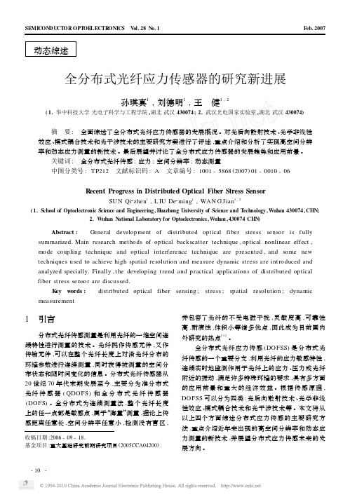
布里渊频移 ,频移量与应力大小成正比 。自发布里 渊散射相对较弱 ,频移量小 (石英光纤对于波长为 1. 3μm 光的应变系数为 5. 8 M Hz/ 10 - 4 ) ,因此测量 谱线移动较为困难 。1993 年 T. Kurashima 等人首 先利用双光源的相干检测方法实现了自发布里渊信 号的检测和分布式应变测量 ,随后又通过引入一个 光频移环路实现了单光源的相干自外差检测 ,克服 了对两光源相干性的要求 。 2. 1. 4 基于相位敏感的光时域反射型 ( Ф2O TDR) 应力传感器[6 ]
利用逆向传输的泵浦光和探测光之间的非线性 效应也可以实现分布式应力传感 。这类传感器动态 范围大 ,测量精度高 ,但需要双端测量 ,系统较复杂 , 同时受到温度的影响 。 2. 2. 1 基于受激拉曼效应的应力传感器
强泵浦脉冲注入单模光纤 ,在斯托克斯波长下 , 与光纤另一端注入的连续探测光相互作用产生非线
Key words : dist ributed optical fiber sensing ; st ress ; spatial resolutio n ; dynamic mea s u re me nt
1 引言
分布式光纤传感测量是利用光纤的一维空间连 续特性进行测量的技术 。光纤既作传感元件 ,又作 传输元件 ,可以在整个光纤长度上对沿光纤分布的 环境参数进行连续测量 ,同时获得被测量的空间分 布状态和随时间变化的信息 。分布式光纤传感器从 20 世纪 70 年代末期发展至今 ,主要分为准分布式 光纤 传 感 器 ( QDOFS) 和 全 分 布 式 光 纤 传 感 器 (DO FS) 。全分布式为连续测量法 ,整个光纤长度 上的任一点都是敏感点 ,属于“海量”测量 ,理论上传 感距离任意长 ,空间分辨率任意小 ,检测没有盲区 ,
长距离布里渊光时域反射光纤传感技术进展
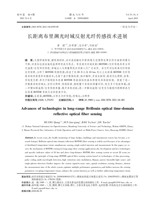
第51卷 第4期 激光与红外Vol.51,No.4 2021年4月 LASER & INFRAREDApril,2021 文章编号:1001 5078(2021)04 0395 09·综述与评论·长距离布里渊光时域反射光纤传感技术进展黄 强1,2,孙军强1,包宇奔1,刘新波2(1 华中科技大学武汉光电国家研究中心,湖北武汉430070;2 多电源地区电网运行与控制湖南省重点实验室,湖南邵阳422000)摘 要:大型桥梁坍塌、建筑物倾斜、冰灾造成输电杆塔倒塌大范围停电等自然灾害新闻屡见不鲜,对类似这些设施的监测研究成为热点。
布里渊光时域反射(BOTDR)光纤传感具有分布式温度/应变同时传感、单端注入与测量等优点而被人们广泛采用。
本文针对长距离光纤传感应用场景,分析了BOTDR传感机理;综述了近20年以来10km及以上长距离BOTDR光纤传感系统的发展和关键技术;总结了基于数据处理、脉冲编码、多波长探测、高消光比调制、拉曼、窄线宽光源、单光子探测技术改善BOTDR性能指标的基本原理及具体指标值。
展望了进一步提高系统信噪比、空间分辨率、传感距离、缩短整个系统的测量时间,优化多个性能参数;进一步增加除温度/应变传感参量,提升系统功能;进一步解决温度/应变交叉敏感问题都将成为长距离BOTDR系统今后的发展方向。
关键词:长距离;BOTDR;分布式光纤传感;信噪比;分辨率中图分类号:O436 3;TN253 文献标识码:A DOI:10.3969/j.issn.1001 5078.2021.04.001Advancesoftechnologiesinlong rangeBrillouinopticaltime domainreflectiveopticalfibersensingHUANGQiang1,2,SUNJun qiang1,BAOYu ben1,LIUXin bo2(1 WuhanNationalLaboratoryforOptoelectronics,HuazhongUniversityofScienceandTechnology,Wuhan430070,China;2 HunanProvincialKeyLaboratoryofGridsOperationandControlonMulti PowerSourcesArea,Shaoyang422000,China)Abstract:Inrecentyears,thehealthmonitoringoflargebridges,buildingsandtransmissiontowershasbecomearesearchhotspot Brillouinopticaltime domainreflection(BOTDR)fibersensingiswidelyusedbecauseofitsadvantagesofdistributedtemperature/strainsimultaneoussensing,single endedinjectionandmeasurement Inthispaper,wereviewthemechanismofBOTDRsensingforlong rangefibersensingapplications;thedevelopmentandkeytechnologiesandspecificindicatorvaluesof10kmandabovelong distanceBOTDRfibersensingsysteminrecent20years;wesummariestheprincipleoflong rangeBOTDRopticalfibersensingsystembasedontechnologiesofdataprocessing,pulsecoding,multi wavelengthdetection,highextinctionratiomodulation,Raman,narrowlinewidthlightsourceandsingle photondetection Furtherimprovethesystemsignal to noiseratio,spatialresolution,sensingdistance,shortenthemeasurementtimeofthewholesystem,optimizemultipleperformanceparameters;andfurtherincreasethesensingparametersexceptingtemperature/strain,enhancethesystemfunction;aswellasfurtheraddressingtemperature/strain基金项目:武汉市科技计划项目(No.2018010401011272);湖南省科技计划重点项目(No.2016TP1023);湖南省教育厅资助科研项目(No.17B239)资助。
华中科大光纤通信chapter 2 optical fiber
2.1 Geometrical Optics & Wave Optics in Fiber
2.1.1 Geometrical Optics
suited for a >> λ Multimode Step-Index Optical Fiber
2 2 n1 -n 2 n1 -n 2 Δ= 2 2n1 n1
2017/10/25 OE, HUST
Cross-phase modulation 交叉相位调制 Large effective-area fiber 大有效面积发光 Phase-matching condition 相位匹配条件 Optical phase conjugation 光相位共轭 Elastic scattering 弹性散射 Inelastic scattering 非弹性散射 Fiber Manufacturing:光纤制作 Doubly clad:双包层 Depressed-cladding fiber: 凹陷包层光纤 Cylindrical preform:预制棒 MCVD:改进的化学汽相沉积 OVD:轴外汽相沉积 VAD:轴向沉积 PCVD:等离子体化学汽相沉积 Flame hydrolysis 火焰裂解 Sintering :烧结 Light-duty cable 轻型光缆 Heavy-duty cable 重型光缆 Connector 连接头 Furnace 熔炉
Fiber-Optic Communication Technology
Chapter 2 Optical Fibers
Chapter 2. Optical Fibers
Geometrical Optics & Wave Optics in Fiber
光纤传感技术-华中科技大学光学与电子信息学院
2.3 分布式拉曼光纤传感系统
2.4 分布式布里渊光纤传感系统
2.5 分布式光偏振时域反射计传感系统
2.6 光纤传感器组网技术
2.7 无源光纤传感网络系统与技术
2.8 有源光纤传感网络系统与技术
第三章光纤光栅传感技术与系统(6学时)
3.1 Bragg光纤光栅传感原理
3.2 基于Bragg光纤光栅的几种传感器
3.3 其他类型的光纤光栅的传感应用
3.4 准分布式光纤光栅传感系统
3.5 光纤光栅传感系统的典型工程应用
第四章基于光子晶体光纤的光纤传感技术(6学时)
4.1 光子晶体光纤的原理与制备技术
4.2 光子晶体光纤的传感特性分析
4.3 基于光子晶体光纤的几种典型传感器
开课学期:spring
总学时:32
学分:2
先修课程要求:fiber optics, physical optics, optical fiber communication
课程组教师姓名
职 称
专 业
年 龄
学术方向
Ming Tang
Prof.
OE
34
Fiber communication and sensing
职 称
专 业
年 龄
学术方向
唐明
教授
光电
34
光纤通信与传感
孙琪真
副教授
光电
31
光纤通信与传感
课程负责教师教育经历及学术成就简介:
唐明教授,博士,教育部新世纪优秀人才支持计划入选者,楚天学者特聘教授,国际电子与电气工程师协会高级会员(Senior member of IEEE),日本应用物理学会会员。2001年于华中科技大学光电子工程系获得学士学位;2001年至2005年于新加坡南洋理工大学(NTU)电子与电气工程学院攻读博士课程并于2005年获得博士学位;2005年至2009年于新加坡南洋理工大学网络技术研究中心(NTRC)从事博士后研究;2009年2月至2011年2月加入日本理化学研究所(RIKEN)极端光子学研究项目组(Extreme Photonics Program)任特别研究员;2011年1月作为引进人才加入华中科技大学。
华中科技大学研究生先进光纤传感课程2015微纳光纤环涂覆聚合物材料测电流-6
Highly Sensitive Current Sensor Based on an Optical Microfiber Loop Resonator Incorporating LowIndex Polymer OverlayMin-Seok Yoon,Soo Kyung Kim,and Young-Geun Han,Member,IEEE,Member,OSAAbstract—A highly sensitive current sensor based on an optical microfiber loop resonator(MLR)incorporating low index polymer is proposed and experimentally demonstrated.The microfiber with a waist diameter of2μm is wrapped around the nichrome wire with low index polymer overlay to realize the MLR as the highly sensitive current sensor.Low index polymer overlay can success-fully reduce round-trip fractional loss resulting in the improve-ment of the Q-factor(Q)and thefinesse(F)of the MLR around the nichrome wire.The use of the microfiber with a waist diameter of2μm and low index polymer with high thermal property can effectively improve the current sensitivity of the proposed MLR to be437.9pm/A2.Index Terms—Electric current sensors,fiber-optic sensors,mi-crofiber,microfiber loop resonator.I.I NTRODUCTIONO PTICAL microfibers have attracted much attention in versatile applications to optical biosensors,nonlinear optical devices for supercontinuum generation,and optical res-onators because of their unique optical properties of the optical microfiber such as,low-loss evanescentfield coupling,strong confinement,and configurability[1]–[4].Many research efforts have focused on the development of optical resonators based on microfibers,which are very useful for many applications to opticalfilters and sensors[5]–[10].The optical resonators based on microfiber are very sensitive to a change in the surrounding environment due to the large evanescentfield in the microfiber [11],[12].Recently,the current sensor based on microfiber knot resonator(MKR)has been reported[13].The current sensor based on the MKR was able to overcome the limitation of previous optical current sensor such as,requirement of very long length offiber due to extremely small Verdet constant of silica and complex manufacturing techniques to coat thefiber [14].However,it is not easy to improve the current sensitivity of the MKR-based current sensor with a copper support rod because of the low value of thermal-expansion coefficient and electric resistivity of the copper wire and undesirable insertion loss in the interface between the copper rod and the MKR. Manuscript received August29,2014;revised October20,2014,November 4,2014,and November12,2014;accepted September12,2014.Date of pub-lication December4,2014;date of current version April29,2015.This work was supported by the Basic Science Research Program through the National Research Foundation of Korea,funded by the Ministry of Education,Science and Technology(2012R1A1A2000999).The authors are with the Department of Physics and the Research Institute for Natural Sciences,Hanyang University,Seoul133-791,South Korea(e-mail: yghan@hanyang.ac.kr).Color versions of one or more of thefigures in this paper are available online at .Digital Object Identifier10.1109/JLT.2014.2371030Fig.1.Experimental scheme for the fabrication of the microfiber.In this paper,we propose a highly sensitive current sensor based on a microfiber loop resonator(MLR)incorporating low index polymer.A microfiber with a diameter of2μm is coiled around a nichrome wire with low index polymer coating to make the MLR as the current sensing probe.The electric current in the nichrome wire increases temperature around the nichrome wire and accordingly changes thermal properties of the MLR with low index polymer overlay.The Q-factor(Q)and thefi-nesse(F)of the MLR around the nichrome wire can be effec-tively enhanced by using low index polymer overlay.Since the main parameter to determine the sensitivity of the MLR-based sensing probe around the nichrome wire to the electric current is the thermal expansion(TE)factor of the MLR,the use of the microfiber with a diameter of2μm and high thermal properties of low index polymer can dramatically increase the current sen-sitivity to be437.9pm/A2which is∼10time higher than the previous result[13].II.O PERATION P RINCIPLE AND F ABRICATIONFig.1shows the experimental scheme for the fabrication of the microfiber to realize the MLR-based current sensor.A conventional single-modefiber on the motorized stage is adi-abatically elongated by using a micro-tapering technique[10]. Heating and elongation processes play a key role in the fab-rication process of the microfiber.The waist diameter of the microfiber and its uniform length were measured to be2μm and20mm respectively.To fabricate the MLR-based current sensing probe,the mi-crofiber was wrapped around the surface of a nichrome wire by using a computer-controlled rotational stage resulting in the for-mation of the MLR surrounding the nichrome wire.The exper-imental procedure and the microscopic image of the fabrication of the MLR with low index polymer coating(PC-373,Luventix) are shown as Fig.2(a)and(b),respectively.The microfiber with0733-8724©2014IEEE.Personal use is permitted,but republication/redistribution requires IEEE permission.See /publications standards/publications/rights/index.html for more information.Fig.2.(a)Experimental procedure of the fabrication of the MLR for the realization of a highly sensitive current sensor,(b)microscopic image of the fabricated MLR with low index polymer coating and(c)microscopic side view of the nichrome wire without and with low index polymer overlay.the strong evanescentfield is readily affected by the external cir-cumstance.Since the nichrome wire has higher refractive index than the microfiber and surface roughness as seen in Fig.2(c), undesirable loss should be arisen from the interface between the nichrome wire and the microfiber.To reduce unwanted loss, the surface of the nichrome wire was coated by UV-curable low refractive index polymer[10],[15].The microfibers were attentively wrapped around the nichrome wire with low index polymer coating and sufficiently cured by using the UV lamp to fabricate the MLR as seen in Fig.2(a).Low index polymer with high thermal quantities has multiple functionalities,such as the effective improvement of the current sensitivity related with the thermal property of polymer,the safe sustenance of the optical resonant coupling,and the mechanical protection.The diameter (=2r n)of the nichrome wire and the thickness(t p)of low index polymer overlay were measured to be0.5,and0.1mm, respectively,as seen in Fig.2(c).To understand the operating principle of the proposed MLR-based current sensor with low index polymer coating,we should have knowledge of the MLR.Fig.3shows the operating prin-ciple of the MLR.For the input light of E1in the microfiber coupling region is split to E3and E4.E3in the microfiber re-gion3has the same phase with respect to E1because of the direct-coupling from the input light E1.Then E3should circu-late in the microfiber loop.E4in the microfiber region4suffers a phase delay ofπ/2with respect to E1and E3because of the cross-coupling from the input light of E1in the microfiber cou-pling region and goes straight to the output port.Since E2is diverted from E3after circulation through the MLR,E3has a phase delay of e jβL(L:the loop length of the MLR)with re-spect to E3in the microfiber region3.Then,the cross-andthe Fig.3.Scheme for the operating principle of the MLR.direct-couplings from E2should additionally generate E3and E4resulting in a supplementary phase delay ofπ/2between E3and E4.The complex amplitudes of E2,E3,E4can be expressed by[16]E2=E3e−α0L e jβL(1)E3=1−γ0(√1−KE1+j√KE2)(2) E4=1−γ0(j√KE1+√1−KE2)(3) whereγ0is fractional coupler intensity loss(0≤γ0≤1).α0is an amplitude attenuation coefficient of the microfiber.K is the in-tensity coupling ratio in the MLR coupling region(0≤K≤1).β(=2πn eff/λ)and L are the propagation constant and the loop length of the MLR.By substituting Eqs.(1)and(2)into Eq.(3), we can obtain the relationship between E1and E4asE4=(1−γ0)e−α0L e jβL+j√1−γ0√K1−j√1−γ0√Ke−α0L e jβLE1(4)By considering Eq.(4)and Euler’s formula,we can achieve the analytical expression of transmittance of the MLR asT=E4E12=(1−γ0)1−(1−K)α1+K(1−α)+2K(1−α)sin(βL)(5)α=1−(1−γ0)e−2α0L(6) whereαis round-trip fractional loss of the MLR,which is closed related with fractional coupler intensity loss(γ0)and an amplitude attenuation coefficient(α0).From Eq.(5),the resonant wavelength(λ)of the MLR can be derived asλ=2πsin−1α−K−12K(1−α)+2mπ−1n eff·L =γ·n eff·L(7)γ=2πsin−1α−K−12K(1−α)+2mπ−1(8)Fig.4.Transmission spectra of the MLR fabricated by winding the microfiber around the nichrome wire without(a,c)and with(b,d)low index polymer overlay,respectively.where n effis the effective index of the microfiber with low index polymer coating.m is a positive integer(>0).And the free spectral range(FSR)and the full width half maximum of the MLR can be derived as[16].FSR=λ2n effL(9)FWHM=λ2n effLαπ√1−α(10)From Eqs.(9)and(10),the Q-factor(Q)and thefinesse(F) of the MLR can be achieved byQ=λFWHM=n effLλπ√1−αα(11)F=FSRFWHM=π√1−αα.(12)From Eqs.(11)and(12),it is evident that the Q-factor(Q)and thefinesse(F)is inversely proportional to the amount of theround-trip fractional loss(α).Fig.4(a)and(c)exhibit theoretical and experimental resultsof transmission spectra of the MLR formed around the nichromewire without low index polymer overlay.The diameter(a)of theMLR to determine the loop length(L=π·a)was∼700μmas seen in Fig.2(c).The effective index(n eff)of the microfiberwithout low index polymer obtained by using afinite elementmethod(FEM)was∼1.4238[17],[18].Numerical parameterswere:α0=200,γ0=0.81,α=0.92,K=0.20.For the caseof the MLR without low index polymer,a high insertion loss of ∼11dB was observed because of high refractive index of the nichrome wire and high scattering loss generated by the sur-face roughness of the nichrome wire[19].The amount of theQ-factor(Q)and thefinesse(F)were measured to5200and2.5,respectively.Fig.4(b)and(d)depict theoretical and exper-imental results of transmission spectra of the MLR configuredaround the nichrome wire with low index polymer overlay.The Fig.5.Theoretical results of variation of(a)round-trip fractional loss of the MLR as a function of the thickness of low index polymer overlay,variation of (b)the Q-factor and(c)thefinesses of the MLR as a function of round-trip fractional loss.effective index(n eff)of the microfiber with low index poly-mer was estimated to be∼1.4259.Numerical parameters were:α0=15,γ0=0.14,α=0.20,K=0.93.Low index polymer overlay is capable of reducing the refractive index difference be-tween the microfiber and the nichrome wire and the scattering loss induced by the surface roughness of the nichrome wire.The reduction of round-trip fractional loss(α)can sequently enhance the intensity coupling ratio(K).It means that the transmission characteristics of the MLR should be consequently improved by low index polymer overlay as seen in Fig.4(b)and(d).The Q-factor(Q)and thefinesse(F)of the MLR with low index poly-mer overlay were enhanced to62000and32.0,respectively.The insertion loss was dramatically reduced to be∼1dB as seen in Fig.4(b)and(d).The theoretical results were good agreement with experimental ones.We theoretically analyzed the variation of round-trip frac-tional loss of the MLR with respect to the thickness of low index polymer overlay by using a beam propagation method as seen in Fig.5(a).Increasing the thickness of low index polymer overlay enclosed the MLR gradually reduces round-trip frac-tional loss(α).Fig.5(b)shows the variation of the Q-factor and thefinesse of the MLR as a function of round-trip fractional loss(α).Reducing round-trip fractional loss(α)can effectively improve the Q-factor and thefinesse of the MLR.Since the nichrome wire has higher refractive index than the silica-based microfiber,the guided mode in the microfiber must be radiated and scattered at the interface between the microfiber and the nichrome wire resulting in additional round-trip fractional loss (α)[19],[20].Low index polymer overlay,however,plays an important role in the reduction of round-trip fractional loss(α) resulting in the improvement of the Q-factor(Q)and thefinesse (F)of the MLR around the nichrome pared with theFig.6.Theoretical result of variation of effective indices of the microfiber with low index polymer overlay as a function of temperature.MLR formed around the copper wire[13],the Q-factor(Q)and thefinesse(F)of the MLR around the nichrome wire with low index polymer overlay were dramatically enhanced by a factor of14and7,respectively.When the electric current is applied to the nichrome wire, thermal properties of the MLR with low index polymer coating should be changed and accordingly the resonant wavelength of the MLR must be shifted[21].From Eq.(7),the sensitivity of the resonant wavelength of the MLR with low index polymer coating to temperature generated by the electric current change can be derived as∂λ∂T =γLn e f fL∂L∂T+∂n e f f∂TTE TO(13)In Eq.(13),it is clearly evident that the dependence of the resonant wavelength of the MLR with low index polymer coat-ing on the electric current is basically composed of the TE and the thermo-optic(TO)terms.As seen in Fig.3,the MLR was formed by winding the microfiber around the nichrome wire in-corporating low index polymer overlay.Since the loop length(L) of the MLR is essentially determined by the diameter(=2r n) of the nichrome wire and the thickness of low index polymer (t p),the TE factor in Eq.(13)can be expressed by[22].n effL ∂L∂T=n effr n+t p∂r n∂T+∂t p∂T=n effr n+t p(r n C v n+t p C v p)(14)where C v n(1.7×10⁻⁵/◦C)and C v p(4.5×10⁻⁴/◦C)are TE coefficients of the nichrome wire and low index polymer,re-spectively.The applied current increases temperature around the nichrome wire with the MLR coated by low index poly-mer resulting in the variation of the radius of the MLR induced by the positive value of C v n and C v p.By considering C v n and C v p,the TE factor in Eq.(13)can be theoretically esti-mated to be1.7×10−4/◦C.To get the TO term in Eq.(13), we analyzed the variation of effective indices of the microfiber with low index polymer overlay as a function of temperature by using FEM.In Fig.6,the external temperature changes the effective index of the microfiber with low index polymer overlay.The negative TO coefficient of low indexpolymer Fig.7.Transmission spectra of the MLR with variations in the electric current: (a)increasing the electric current,(b)decreasing the electric current,and(c) resonant wavelength shift of the proposed sensing probe as a function of the electric current.(−3.4×10⁻⁴/◦C)is more dominant than the positive one of the microfiber(9.0×10⁻⁶/◦C),the TO factor in Eq.(13)is theo-retically estimated to be−1.3×10⁻⁵/◦C as seen in Fig.6.It is evident that the positive TE factor(1.7×10⁻⁴/◦C)in Eq.(13) is10time higher than the negative TO one(−1.3×10⁻⁵/◦C). Consequently,the resonant wavelength of the proposed MLR-based current sensor eventually shifts into longer wavelength as the electric current increases.By considering the variation of temperature induced by the electric current[23],the wavelength shift of the MLR around the nichrome wire with low index polymer overlay can be written asΔλ=γLn effr n+t p(r n C v n+t p C v p)+∂n eff∂TI2RG T(15) where I is the electric current.R is the resistivity.G T is the thermal conductance of ambient temperature sink[23].From Eq.(15),it is noticeable that the wavelength change of the MLR around the nichrome wire with low index polymer overlay is proportional to the square of the electric current.III.E XPERIMENTS AND R ESULTSWe measured the transmission characteristics of the MLR-based current sensor with variations in the electric current by us-ing an optical spectrum analyzer(ANDO,AQ6317)and an am-plified spontaneous emission(ASE)source(ANDO,AQ4315A) as an input light source.The direct current(DC)current was di-rectly applied to the nichrome wire of the fabricated MLR-based current sensor using a DC power supply.Fig.7(a)depicts the transmission spectra of the proposed sensor based on the MLR as the electric current increases. The nichrome wire with the electric currentflow acts as a heating element resulting to instantaneous temperature riseTABLE IS ENSITIVITIES TO THE ELECTRIC CURRENT,SENSING RANGE AND INSERTION LOSS OF DIFFERENT TYPES OF CURRENT SENSORSType of current sensor Sensitivity Current range Loss MKR with copper wire[13]51.3[pm/A2]2[A]UnknownInline microfiber MZIwith copper wire[24]140.3[pm/A2]3[A]12[dB]Proposed MLR with lowindex polymer overlay437.9[pm/A2] 1.2[A]∼1[dB]in the MLR-based current sensor.Accordingly,the resonant wavelength of the proposed sensing probe is shifted to longer wavelengths by increasing the electric current around the nichrome wire.At a loading current of1.0A,the amount of the resonant wavelength shift was measured to be∼440pm. Decreasing the electric current around the nichrome wire made the resonant wavelength shifted to shorter wavelengths because of the reduction of temperature in the proposed sensing probe as seen in Fig.7(b).No difference of resonant wavelength shifts by increasing or decreasing the electric current was observed. Fig.7(c)shows the resonant wavelength shift of the MLR as a function of the electric current.The linearfitting curve of current sensitivity of the proposed sensing probe was∼437.9 pm/A2with a correlation coefficient(R2)of0.9993.The measurement range of the electric range is mainly determined by the FSR of the MLR.It means that the measurement range of the electric current can be enhanced by reducing the diameter of the MRL.In our experiment,since the diameter of the MLR was∼700μm resulting to a FSR of0.75nm,the measurement range of the electric current is∼1.2A.However,the use of a nichrome wire with a small diameter can enhance the FSR of the MLR andfinally the measurement range of the electric current based on the proposed sensing method.In Table I,we compared the performance of the proposed sensing probe with the previous results in terms of current sensitivity,measurement range of the electric current,and insertion loss.The proposed current sensing method has a low insertion loss of∼1dB.IV.C ONCLUSIONA highly sensitive current sensor based on the MLR incor-porating low index polymer with high thermal properties was proposed and experimentally demonstrated.To reduce an unde-sirable loss arose in the interface between the nichrome wire and the microfiber with the large evanescentfield,the nichrome wire wasfirstly coated by low index polymer.The microfiber with a waist diameter of2μm around the nichrome wire with low index polymer coating was coiled to realize the MLR with high current sensitivity.Since low index polymer effectively miti-gated round-trip fractional loss(α)of the MLR,the Q-factor (Q)and thefinesse(F)of the MLR around the nichrome wire could be adequately enhanced.The insertion loss of the pro-posed current sensing probe was measured to be∼1dB,which was12times lower than the previous result[24].Since the TE term of the MLR played a key role in the sensitivity of the MLR to temperature produced by the electric current,a small waist diameter of the microfiber and low index polymer with high thermal quantities could additionally increase the current sensitivity of the proposed MLR-based sensor.The current sen-sitivity of the proposed MLR-based sensor was measured to be 437.9pm/A2,which was∼10times higher than the previous result[13].R EFERENCES[1]Y.Chen,Z.Ma,Q.Yang,and L.Tong,“Compact optical short-passfilters based on microfibers,”Opt.Lett.,vol.33,no.21,pp.2565–2567, Nov.2008.[2]G.Brambilla,“Opticalfibre nanowires and microwires:A review,”J.Opt.,vol.12,no.4,pp.1–19,Apr.2010.[3]Y.Li and L.Tong,“Mach–Zehnder interferometers assembled with op-tical microfibers or nanofibers,”Opt.Lett.,vol.33,no.4,pp.303–305, Oct.2011.[4]J.Wo,G.Wang,Y.Cui,Q.Sun,R.Liang,P.P.Shum,and D.Liu,“Refrac-tive index sensor using microfiber-based Mach–Zehnder interferometer,”Opt.Lett.,vol.37,no.1,pp.67–69,Jan.2012.[5]M.Sumetsky,“Opticalfiber microcoil resonators,”Opt.Exp.,vol.12,no.10,pp.2303–2316,May2004.[6]Y.Chen,F.Xu,and Y.Q.Lu,“Teflon-coated microfiber resonator withweak temperature dependence,”Opt.Exp.,vol.19,no.23,pp.22923–22928,Nov.2011.[7]X.Jiang,Y.Chen,G.Vienne,and L.Tong,“All-fiber add-dropfilters basedon microfiber knot resonators,”Opt.Lett.,vol.32,no.12,pp.1710–1712, Jun.2007.[8]Y.Chung,“Time-domain numerical investigation of ring resonator opticaldelay devices,”J.Opt.Soc.Korea,vol.17,no.5,pp.441–446,Oct.2013.[9]X.Zeng,Y.Wu,C.Hou,J.Bai,and G.Yang,“A temperature sensor basedon optical microfiber knot resonator,”mun.,vol.282,no.18, pp.3817–3819.Sep.2009.[10]M.S.Yoon,H.J.Kim,G.Brambilla,and Y.G.Han,“Development ofa small-size embedded optical microfiber coil resonator with high Q,”J.Korean Phys.Soc.,vol.61,no.9,pp.1381–1385,Nov.2012.[11] F.Xu,P.Horak,and G.Brambilla,“Optical microfiber coil resonatorrefractometric sensor,”Opt.Exp.,vol.15,no.12,pp.7888–7893, Jun.2007.[12] F.Xu and G.Brambilla,“Demonstration of a refractometric sensor basedon optical microfiber coil resonator,”Appl.Phys.Lett.,vol.92,no.10, pp.101126–1–101126-3,Mar.2008.[13]K.S.Lim,S.W.Harun,S.S.A.Damanhuri,A.A.Jasim,C.K.Tio,andH.Ahmad,“Current sensor based on microfiber knot resonator,”Sens.Actuator A,Phys.,vol.167,no.1,pp.60–62,May2011.[14] B.Culshaw,“Opticalfiber sensor technologies:Opportunities and perhapspitfalls,”J.Lightw.Technol.,vol.22,no.1,pp.39–50,Jan.2004. [15] F.Xu and G.Brambilla,“Embedding optical microfiber coil resonators inTeflon,”Opt.Lett.,vol.32,no.15,pp.2164–2166,Aug.2007.[16]L.F.Stokes,M.Chodorow,and H.J.Shaw,“All-single-modefiber res-onator,”Opt.Lett.,vol.7,no.6,pp.288–290,Feb.1982.[17] F.Xu,P.Horak,and G.Brambilla,“Optical microfiber coil resonatorrefractometric sensor,”Opt.Exp.,vol.15,no.12,pp.7888–7893, Jun.2007.[18]J.L.Kou,J.Feng,Q.J.Wang,F.Xu,and Y.Q.Lu,“Microfiber-probe-based ultrasmall interferometric sensor,”Opt.Lett.,vol.35,no.13, pp.2308–2310,Jul.2010.[19]P.Polynkin, A.Polynkin,N.Peyghambarian,and M.Mansuripur,“Evanescentfield-based opticalfiber sensing device for measuring the refractive index of liquids in microfluidic channels,”Opt.Lett.,vol.30, no.11,pp.1273–1275,Jun.2005.[20]X.Guo,Y.Li,X.Jiang,and L.Tong,“Demonstration of critical couplingin microfiber loops wrapped around a copper rod,”Appl.Phys.Lett., vol.91,no.7,pp.073512–1–073512-3,Aug.2007.[21]G.Y.Chen,T.Lee,Y.Jung,M.Belal,G.Brambilla,N.Broderick,andT.P.Newson,“Investigation of thermal effects on embedded microcoil resonators,”in Proc.Eur.Quantum Electron.Conf.,May2011,p.Ch2_2.[22]Y.Wang,M.Sasaki,and T.Hirai,“Thermal properties of chemicalvapour-deposition SiC-C nanocomposites,”J.Mater.Sci.,vol.26,no.20, pp.5495–5501,Oct.1991.[23] C.J.and M.J.Mcnutt,“Effects of substrate thermal characteristics on theelectromigration behavior of Al thinfilm conductors,”in Proc.Annu.Rel.Phys.Symp.,Apr.1983,pp.24–31.[24] A.A.Jasim,S.W.Haruna,M.Z.Muhammad,H.Arof,and H.Ahmad,“Current sensor based on inline microfiber Mach–Zehnder interferome-ter,”Sens.Actuators A,vol.192,pp.9–12,Apr.2013.Min-SeokYoon was born in Mokpo,South Korea.He received the B.S.degree from the Department of Physics,Hanyang University,Seoul,South Korea,in 2010.He started working toward the M.S.degree at the Department of Physics, Graduate School of Hanyang University,in2010.His research interests include opticalfiber nanowires,optical sensor andfiber laser applications.He was a Visiting Researcher at the Optoelectronics Research Centre,University of Southampton,from June2011to July2011.Soo Kyung Kim was born in Pohang,South Korea.He received the B.S.degree from the Department of Physics,Yeungnam University,Gyeongsan,South Ko-rea,in2014.He started working toward the M.S.degree at the Department of Physics,Graduate School of Hanyang University,Seoul,South Korea,in2014. His research interests include optical sensor andfiber laser applications.Young-Geun Han(M’05)was born in Busan,South Korea.He received the M.S.and Ph.D.degrees in information and communications engineering from the Kwangju Institute of Science and Technology,Kwangju,South Korea,in 1999and2003,respectively.He was a Visiting Researcher at the Department of Electrical and Computer Engineering,Johns Hopkins University,Baltimore,MD,USA,from January 2002to July2002.He was a Senior Member of Technical Staff,Korea Institute of Science and Technology,Seoul,South Korea,from2003to2006.He was a Visiting Researcher at the Integrated Research Center for Photonic Networks and Technologies,Pisa,Italy,from July2006to September2006.In2007,he joined the Faculty of Department of Physics,Hanyang University,Seoul.He was a Visiting Associate at the California Institute of Technology,Pasadena,CA, USA,from2013to2014.His research interests include opticalfibers,nonlinear fiber optics,photonic crystalfibers,fiber gratings,all-optical signal processing, optical communication systems,opticalfiber amplifiers,opticalfiber sensors, nano/bio photonics including optical coherent tomography,and bio sensors.He is an author and/or coauthor of more than300international journal and confer-ence technical papers.He has served as a committee member and an invited speaker for various international conferences.He is serving as various international and domestic conference organizing and technical committee members including the Inter-national Conference on Optical Fiber Sensors,Asia Pacific Optical Sensors Conference,Asia Communication and Photonics Conference,Photonics Global Conference,Asia-Pacific Bio-Photonics Conference,OptoWin Conference,and Photonics Conference.He is also serving as an Executive Editor for the Journal of the Optical Society of Korea and as a Topical Editor for the Current Applied Physics.He is a Fellow of the Korean Physics Society,a Fellow of the Optical Society of Korea,a Member of the IEEE Lasers and Electro-Optics Society,and the Optical Society of America.。
光纤传感技术 优秀的外文书籍
光纤传感技术优秀的外文书籍以下是 7 条关于光纤传感技术优秀外文书籍的描述及例子:1. "Optical Fiber Sensor Technology: A Comprehensive Guide" - 这本书就像一把打开光纤传感技术奇妙世界的钥匙!比如,想象一下能够像拥有千里眼一样精确地监测各种物理量,那多厉害啊,这本书就能带你领略其中奥秘。
2. "Advanced Fiber Optic Sensing" - 哇塞,它简直是光纤传感技术的进阶宝典!就好像一位资深导师,一步步引领你深入这个领域,你不想跟着它探索一番吗?3. "Fiber Optic Sensing Systems and Applications" - 看这本书,就如同踏上一场刺激的冒险之旅!比如在大型工程中,光纤传感就像忠实的卫士,默默守护着一切,这里面的知识多有趣呀。
4. "Fundamentals of Fiber Optic Sensing Technology" - 这绝对是基础中的宝藏啊!好比万丈高楼的基石,没有它怎么能行呢?赶紧来好好研读吧。
5. "Practical Fiber Optic Sensing" - 这本书超级实用的好不好!就像给你一双灵巧的手,让你能够实际操作起来,难道你不想拥有吗?6. "Emerging Trends in Fiber Optic Sensing Technology" - 哇,这里面都是崭新的趋势呢!如同站在科技前沿的瞭望塔,能让你先人一步看到未来,还等什么呢?7. "Understanding Fiber Optic Sensing: From Basics to Applications" - 这就是帮助你全面理解的好帮手呀!就像一盏明灯,照亮你在光纤传感技术领域前行的路,不读不行啊。
光纤传感器基本原理
第五章 光纤传感器基本原理
采用双波长工作方式的目的是为了消除测量中多种因素 所造成的误差。取绿光 (1=558nm)作为参考光,红光 (2 =630 nm)作调制检测光,探测器接收到的绿光与红光强 度的吸收比值为R,pH值与R的关系为
第五章 光纤传感器基本原理
可渗透的 薄膜容器 装入直径为5~10 mm的聚丙酸脂小 球,并用指示剂将 小球染色
透过率受到外界 物理量的调制
由于指示剂的透明度在红色光谱区域对 pH 值非常敏 感,在绿色区域却与 pH 值无关。所以,当白光由光 纤导入浸泡在被测溶液中的 pH 探头后,经过用指示 济染色的聚丙酸脂小球的散射,得到反映溶液 pH 值 的光信号。
根据上式,可以设计出多普勒光纤流速、流量测量 传感器
多普勒光纤流速测量技术 第五章 光纤传感器基本原理
设光源频率为f,经半反射镜进入光纤射入到被测流体,
当流体以速度υ 运动时,根据多普勒效应,其向后散射
光的频率为f +Δ f 或f –Δ f (视流向而定)
f f 2 f f
c
(cos 1 cos 2 )
第五章 光纤传感器基本原理
可渗透的 薄膜容器 装入直径为5~10 mm的聚丙酸脂小 球,并用指示剂将 小球染色
光信号由光纤导出进入旋转的双色滤光器,从而使 红光和绿光交替地投射到光电二极管探测器上,通 过信号处理系统把这两种颜色 ( 波长 ) 的光强信号的 比值测量出来.测量结果直接反映被测溶液的pH值。
光纤传感技术
Optical fiber sensors
第
五
章
opticalfibersensors 光纤传感器基本原理
Fundamental of Optical Fiber Sensor
- 1、下载文档前请自行甄别文档内容的完整性,平台不提供额外的编辑、内容补充、找答案等附加服务。
- 2、"仅部分预览"的文档,不可在线预览部分如存在完整性等问题,可反馈申请退款(可完整预览的文档不适用该条件!)。
- 3、如文档侵犯您的权益,请联系客服反馈,我们会尽快为您处理(人工客服工作时间:9:00-18:30)。
2015/9/10
13
Differential reflective fiber-optic angular displacement sensor
Suppress the common mode noise caused by the disturbance in intensity and detector׳s electrical drift, and achieve higher anti-interference capacity;
2015/9/10
3
S2: Intensity modulated OFS
• • • • Basic structures Other types of intensity based OFS Property, pros & cons Special structures
2015/9/10
4
S2-1: Basic structures
7
• Displacement underground induce microbending of fibers; • Microbending loss is measured by OTDR for distributed displacement sensing application. 2015/9/10
2015/9/10 5
S2-1: Basic structures
Transmission type
• Similar to a movable reflector • Used as distance or strain sensors
Limitation: no reference signal so it suffers from light source intensity fluctuation and fiber loss varies
2015/9/10 6
S2-2: Other intensity based types:
Microbending fiber sensor
No bending, fiber is straight
2015/9/10
Heavy pressure applied cause microbending loss
ቤተ መጻሕፍቲ ባይዱ
2015/9/10
11
S2-3: Property of intensity based types: • Versatile • Simple design and easy signal interpretation • Usually suffer from intensity fluctuations and low sensitivity • Variation of light source, fiber loss, modal power distribution, long-term drift
8
S2-2: Other intensity based types:
Intensity based force sensor
2015/9/10
9
S2-2: Other intensity based types:
Liquid level fiber sensor
Liquid
2015/9/10
2015/9/10
2
Recall what we learned last lecture:
• • • • • Overview Sensor capabilities Advantages Sensor types Review of fiber optics
– Absorption, scattering, NA…
2015/9/10
Sensors and Actuators B 208 (2015) 315– 319
15
A novel and compact fiber MI-based sensor was demonstratedby means of splicing a section of TCF to a standard SMF with acore offset. The core offset and the TCF length were improved to8 m and 3 mm, respectively, in order to achieve a large fringe con-trast of up to 18 dB. Such a MI-based RI sensor based on intensitymodulation exhibits a high sensitivity of at the −202.46 dB/RIU atthe refractive index of 1.42, which is two or three times higherthan that of other intensity-modulated RI sensors reported previ-ously. Moreover, the RI sensor is insensitive to temperature, thusovercoming the cross sensitivity problem between surrounding RIand temperature. Our MIbased RI sensor also exhibits the advantages of compact size (8 mm), simple structure, easy fabrication,and good repeatability.
Optics & Laser Technology 2015/9/10 Volume 68, 2015, 124–128
14
Intensity modulated refractive index sensor based on optical fiberMichelson interferometer
光纤传感系统与网络 Optical fiber sensor system and networks
鲁平 Ping Lu
华中科技大学光学与电子信息学院 光通信与光网络系 Email: pluriver@
Lecture note 2
Session 1 – Fundamental concept and components
2015/9/10 12
S2-4: Special structures
Differential intensity type
• Mitigating the power fluctuation issue by using differential intensity signal from sensing arm and reference arm • Pout1-Pout2 ∞ L1-L2
2015/9/10 16
Split-spectrum intensity-based optical fiber sensors for measurement of microdisplacement,strain, and pressure
The power ratio of the sensing signal to the reference signal is thus a function of the air-gap separation. However, because the two signals travel along the same optical path in the fiber and are also radiated from the same source, they carry the same information concerning the fiber losses and sourcepower fluctuations. The power ratio should therefore be immune to variations in both the fiber losses and the source power. Thus a low drift and a high long-term accuracy may be expected for this system. The output of a broadband source is coupled into a multimode fiber and propagates through a fiber coupler and mode scrambler to the sensor.The short-wave-pass interference edge filter, which is attached to or directly fabricated on the output end face of the lead-in–lead-out optical fiber, reflects the portion of the spectrum above its cutoff wavelength but allows the portion of the spectrum below its edge wavelength to transmit. The reflected signal, referred to as the reference signal, returns directly to the fiber. The light transmitted through the filter,referred to as the sensing signal, propagates across the air gap to the mirror. The light is reflected by the mirror and is then partially recoupled into the fiber. The two reflections travel along the same fiber to the detector end and are separated spectrally by the wavelength division multiplexer WDM or demultiplexer. The function of the mode scrambler is to ensure similar MPD’s for the two signals. The intensity of the reference signal is independent of the air gap in the sensor,but the intensity of the sensingsignal is a function of the air-gap separation. 17