60 Series Tube Fitting
Swagelok 针穿阀门目录 PDF说明书

Parker Hose 产品目录说明书
More of what you need to work smarter,AccessoriesV i s u a l I n d e x59RG D-17T1RG D-17Partek Sleeve D-18ParKoil™ (PG) D-19GuardsO-Rings for CA, CE,CF MetricFlange “D” Rings Caterpillar ® Style FlangesT ube O-Ring Fittings and CompressorFittingsO-Rings for Compression Fittings (IT126)O-Rings for C9, OC, 1C Metric Swivels88HC-H Clamp D-2488DB Clamp D-24Hose Assembly D-26Workstations3/4 Reel Rack D-2772B-Cabinet D-28HR6 Hose Bin D-28Hose Adapters D437° Flare Metric Triple-Lok ®Sizes: 6 mm – 38 mmMaterials : Steel, Stainless Steel Pressures : Up to 7200 psi60° Cone BSPPK4Sizes : 1/8” – 2”Materials : Steel Pressures : Up to 5000 psi30° Flare Komatsu StyleSizes : M14 x 1.5 – M33 x 1.5Materials : Steel Pressures : Up to 4000 psiO-Ring Face-Seal Metric Seal-Lok™Sizes: 1/4” – 2”Materials: Steel, Stainless Steel Pressures: Up to 9200 psiJapanese Industrial Standard JISSizes : 1/4” – 1”Materials : Steel Pressures : Up to 5000 psiWhen ordering Parker Adapters, please state the Catalogued Number of each type of adapter desired. Be sure to double check tube and hose sizes of items required.To select proper seal materials for specific applications, refer to Media Compatibility Chart in Tube Fitting Catalog 4300, or contact your Parker Tube Fitting Distributor.If in doubt about which type or size of fitting to specify, consult your Parker Tube Fitting Distributor. In addition Parker Field Sales, Technical Services,the Tube Fitting Division and your local Parker Service Center will help you find answers to all your issues.Phone: (614) 279-7070Fax: (614) 279-7685Web: /tfdNote: Refer to Parker Catalog 4300 for more detailed application information.CALL TOLL-FREE 1-800-C PARKER (1-800-272-7537)Parker Information Center for catalogs, literature or additional information.O-Ring Face-Seal Seal-Lok™ Sizes: 6 mm – 38 mm Materials: Steel, Stainless Steel Pressures: Up to 9200 psi37° Flare FittingsTriple-Lok ®Sizes: 1/8” – 2”Materials: Steel, Stainless Steel, BrassPressures: Up to 9000 psiPipe Fittings and Port AdaptersSizes: 1/8” – 2”Materials : Steel, Stainless Steel, BrassPressures : Up to 7200 psiPipe SwivelsSizes : 1/8” – 2”Materials : Steel, Stainless Steel Pressures : Up to 5000 psiConversion AdaptersSizes: 1/4” – 1-1/2”Materials : Steel, Stainless Steel Pressures : Up to 7700 psiHydraulic Flange and Flange AdaptersSizes : 3/4” – 3”Materials : Steel, Stainless Steel Pressures : Up to 6000 psi15T3SAE (Code 61) Flange – Male SAE (JIC) 37˚ FlareCaution: Do not use the T3 flange to tube or swivel nut to tube adapter in hose assembly applications inwhich pressures exceed the SAE100R2 working pressure range.17T3SAE (Code 61) Flange – Male SAE (JIC) 37˚ Flare - 45˚ Elbow19T3SAE (Code 61) Flange – Male SAE (JIC) 37˚ Flare - 90˚ Elbow39T3Male - Female Swivel - SAE (JIC) 37˚ - 90˚ Elbow41T3Male - Female Swivel - SAE (JIC) 37˚ - 90˚ Elbow - Long4AH3SAE Code 61 Flange - Male SAE (JIC) 37˚ Flare - 5000 psi Caution: Do not use the T3 flange to tube or swivel nut to tube adapter in hose assembly applications in which pressures exceed the SAE100R2 working pressure range.4FH3SAE Code 61 Flange - Male SAE (JIC) 37˚ Flare - 5000 psi -45˚ Elbow4NH3SAE Code 61 Flange - Male SAE (JIC) 37˚ Flare - 5000 psi -90˚ Elbow6AH3SAE Code 62 Flange - Male SAE (JIC) 37˚ Flare6FH3SAE Code 62 Flange - Male SAE (JIC) 37˚ Flare - 45˚ Elbow4AJMCode 61 Flange - Male Seal-Lok4FJMCode 61 Flange - Male Seal-Lok - 45˚ Elbow4NJMCode 61 Flange - Male Seal-Lok - 90˚ Elbow6NH3SAE Code 62 Flange - Male SAE (JIC) 37˚ Flare - 90˚ Elbow6NJMCode 62 Flange - Male Seal-Lok - 90˚ Elbow6FJMCode 62 Flange - Male Seal-Lok - 45˚ Elbow6AJMCode 62 Flange - Male Seal-LokNote:*5000 psi with 4A, 4F and 4N Fittings and 50H Flange Halves.There are two non-interchangeable SAE split flanges: a: S tandard or Code 61 is for 3,000psi to 5,000psi maximum, depending on size.b.H igh Pressure or Code 62 is for 6,000psi maximum, r egardless of size. The flange head is “V” notched for identification.Consult these tables to determine flange halves and flange kits specifications.High Pressure (Code 62)Standard Pressure (Code 61)Note: For use with 4A, 4F and 4N Flanges.50H5000 psi Flange Half (Code 61)Note: For use with 4A, 4F and 4N Flanges.Note: High pressure applications also require the use of Code 61 Flange End hose fittings.51HSAE Flange Half (Code 61)5050HK5000 psi Flange Kit (Code 61)5151HKSAE Flange Kit (Code 61)HFHSAE Flange Half (Code 62) HFHFHKSAE Flange Kit (Code 62) 8FHFlange Half (8000 psi)8FHFHKFlange Kit (8000 psi)DIN and ISO Metric PortsDIN (German) and ISO (International Organization for Standardization) flange heads are the same as SAE flange heads. By comparison, the ports have the same configura-tion except that the DIN and ISO Type I ports accept metric bolts. This requires specialflange halves in most sizes.Note: High pressure applications also require the use of Code 62 Flange End hose fittings.M1HDIN (ISO) Flange HalfM1M1HKDIN (ISO) Flange Kit (Code 61)M2M2HKDIN (ISO) Flange Kit (Code 62)M2HDIN (ISO) Flange Half (Code 62)711509O-Rings - SAE Thread (Compound N552-90)*711510O-Rings - Code 61 and Code 62 Flanges (Compound N552-90)**Note: F or use with petroleum base fluids, other compounds available for Phosphate Ester fluids.Please contact The Parker Hannifin Seal Group/O-Ring Division (1-800-C-PARKER) for additional information.C9RG O-Rings for CA, CE, CF MetricC9RG O-Rings for C9, OC, 1C Metric SwivelsD9DTBonded Seal for BSPP Port Fittings*Note: D 9DT must be ordered from the Tube FittingsDivision. Please contact TFD for additional size and product information.XARGFlange “D” Rings Caterpillar ®Style FlangesJ0RGO-Rings - Seal-Lok ®Note: O -Rings for use in Seal-Lok ® connections are illustrated in actual size. Part numbers for O-Ringsused in Seal-Lok ® and in SAE port connections are also listed in the table. O-Rings are supplied in Nitrile NBR compound, 90 durometer hardness.SAE 711509-4-8Seal-Lok J0RG-8-8Photo shows an actual comparison between an SAE port O-Ring (top) and a Seal-Lok ® O-Ring (bottom). They differ in both diameter and cross section.8ARGFlange “D” Rings for 76 Series Style FlangeT1RGO-Rings for Compression Fittings (1T126)Charge Ports CapsR134aR12CORGCaptive O-Ring Assembly ToolsParker’s new CORG Assembly Tools are designed to facilitate the installation of the O-Ring into the half-dovetail groove of the O-Ring face seal fitting.Note: C ORG Assembly T ools must be ordered from the T ube Fittings Division (614) 279-7070.Note: O -Rings listed are for use with petroleum base fluids. Other compounds are available for Phosphate Ester fluids by special order. For Viton ® or otherO-Ring compounds, consult Parker Hannifin, Seal/O-Rings Products Division (1-800-C-PARKER.)Bench TypeHand Type59RGO-Rings for Tube O-Ring Fittingsand Compressor FittingsNote:T he above O-Rings (RG) have HNBR compound number N1195-70 (green).Accessory Selection Guide – Partek Sleeve (AS-B, AS-Y or PS)Note: T he inside flat “A” dimension correspondswith the inside diameter “B” dimension. For example, AS-Y -13 flat surface “A” is 1.34 in. This offers a .86 in. inside diam-eter “B”. Hose with a smaller O.D. can be specified for this size sleeve. Parker 201-5 hose has a .58 in. O.D. and can easily be inserted in the Partek AS-Y -13Sleeve.Note: 1. T he dimensions shown are related to the hose outside diameter and may not fit over the fitting. For over the fitting applications, a larger sizesleeve may be required.2. Cut lengths are available. Contact your local distributor for prices ().Partek SleevePartek “PS” SleeveParker’s Partek Nylon Protective Sleeving gives you tough hose abrasion protection two ways. First, per the ISO 6945 specification, Partek has a unique tubular weave nylon construction, Partek “AS” is strong enough to withstand greater than 200,000 abrasion cycles without wearing through the fabric at any loca-tion. Partek “PS” can withstand greater than 50,000 abrasion cycles. In addition, this weave also gives an exceptionally smooth interior wall, allowing rubber hose to move freely inside the sleeve. This provides easy installation and prevents any internal abrasion problems. Partek sleeving is available in either black or yellow and in sizes to fit most hydraulic hose. Partek, the quick and easy solution to hose protection in high-abrasion areas.Temperature Range: -67°F to +248°F (-53°C to +120°C)Accessory Selection Guide – PolyGuard (HG)• S hield hose from abrasion and cuts • Minimize kinking• Cannot rust or corrode • R esist water, oil, gasoline, hydraulic fluid, and most solvents • I deal for bundling plastic tubing or hose lines • E asy to install without removing hose lines; no clamps neededPolyGuardHeavy-duty polyethylene provides protection in rugged operating conditions.Great for b undling high-pressure hose lines.Cut edges can be smoothed by applying heat.CAUTION: This material will support combustion.Color: BlackTemperature Range:0˚F to +200˚F (-17˚C to +93˚C)Parkoil ™Lower-cost protection for applications that call for a tighter bend radius and are less demanding.Cut edges can be smoothed by applying heat.CAUTION: This material will support combustion.Color: BlackTemperature Range:0˚F to +200˚F (-17˚C to +93˚C)Accessory Selection Guide – ParKoil ™ (PG)Accessory Selection Guide – Spring Guard and Armor GuardNote:Spring Guard and Armor Guard are packaged in 10 ft. pieces.Parker Spring Guard and Armor Guard are two products that prolong the life of hose lines that are exposed to rugged operating conditions. They distribute bending radii to avoid kinking in hose lines and protect hose from abrasion and deep cuts. Guards areconstructed of steel wire and plated to resist rust.Spring Guard (SG)Armor Guard (AG)Accessory Selection Guide – Firesleeve (FS-F)Parker Firesleeve is a flame resistant sheath that protects the hose from extreme temperature conditions. Firesleeve easily slides over hoses and readily expands over fitting. It can be assembled with Parker FSC or properly sized wormgear clamp.Construction: Braided fiberglass sleeve and an orange,bonded and seamless silicone rubber cover.Specifications: Conforms to SAE Aerospace Standard 1072A Type 2A.Temperature Range:-54˚C to +260˚C (-65˚F to +500˚F).Note: T he Firesleeve inside dimension (I.D.)must exceed the outside diameter (O.D.) of the hose and offer an allowance for easy hose insertion. For example, 201-16 has a 1.23 in. O.D. FS-S-24, with an I.D. of 1.46 in., is the suggested Firesleeve. Note: P arker FSC Clamp fits all hoses up to2 in. O.D. Note: P arker HC Clamps (wormgear) are listedon page D-24.Note: See Page D-22 for Firesleeve assembly instructions.Firesleeve (FS-F)FSC ClampPart Number: FSC(One size fits all hoses up to 2 inch O.D.)Accessory Selection Guide – Firesleeve (cont.)1. A ssemble one end fitting on hose. Cut firesleeve to same length as hose. Cover approximately 1” of each end of fire-sleeve with FSS sealant and allow to dry.2. P ush firesleeve back from cut end of hose and assemble the second end fitting. Then pull firesleeve completely over both sockets.3. I nsert tail of FSC clamp into FST clamping tool.4. P osition clamp around middle of socket and tighten with tool. Bend end of band back over buckle. Repeat on other end.Repair any scuffs or abrasions in firesleeve with FSS sealant.FSC ClampUsed to attach firesleeve around socket on hose sizes with a 2” maximum O.D.FST Clamp ToolPart Number: FST -711617 Used to secure FSC clamp.FSS Firesleeve SealantKeeps end of firesleeve from fraying - for neater, longer lasting installation.FiresleeveAssembly InstructionsAccessory Selection Guide – CL ClampVinyl coated steel clamps provide hose support where long lengths are used. Provides neater installation of hose lines, minimizes hose chafing and prevents damage to hose.Material: CR Steel with Zinc PlatingCoating: Black Vinyl Plastisol - 0,8 mm (0.03 inch) thick.Temperature Range:-40°C to +107°C (-40°F to +225°F).Accessory Selection Guide – HC, 88HC-H and 88DB ClampThe Parker HC Clamp is a stainless steel worm gear clamp designed for low presure industrial hose applications.Material: Stainless steelSpecifications: SAE J1508, Type F and Type HD88HC-HSeries Hose Clamp(High Torque Wormgear)88DBSeries Heavy Duty Hose Clamp(Double Bolt Hose Clamp)HC Hose Clamp TableNote: See 88 Series Assembly Instructions for proper 88HC-H clamp attachment.Accessory Selection Guide – Protection Shields (HP , HT, and HP-B)Prevent hose abrasion while extending your hose life. Parker Hose Protection Shields extend hose life by protecting the hose from abrasion that occurs when hose rubs against other hose, metal or concrete. Parker hose shields are resistant to oil, lubricants, gasoline, most solvents and can withstand ambient temperatures from -40° to +300° F . Easily installed and secured by cable ties without disconnect-ing any hose lines. Use with hose from 1/4” to 2” I.D.♦ Eliminate hose abrasion on concrete, metal or any rough surface. ♦ Guard against hose deterioration on mobile hydraulic equipment. ♦Let Parker fill all your hydraulic and pneumatic hose product needs.Hose Protector Shields are a fast and extremely cost effective way to isolate fluid lines from direct contact with other lines, components or structural members. They’re available in 4-inch, 6-inch and 8-inch lengths and the width can be trimmed to satisfy a variety of situations. These flexible protectors simply clamp around the hose and are securely held in place by nylon cable ties which are included. The cable ties are recessed in molded grooves to protect them from abrasion. You don’t need to disconnect a line to install a Parker Hose Protector Shield the way you do with a continuous tubular sleeve. Just wait until the installation is up and running to see exactly where contact needs to be prevented.Parker Hose Protector Shields are available in bulk quantities and in convenient assortments in 4”, 6” and 8” sizes. Cable ties are included with all protectors and are also available in bulk.Hose ShieldsTie Wraps HP-B-13X18-KIT2 ea. HP-13 RFL HT -12-KIT 30 ea. HT -12 Tie Wraps 2 ea. HP-15 RFL HT -16-KIT 30 ea. HT -16 Tie Wraps4 ea. HP-18 RFLHT -22-KIT15 ea. HT -22 Tie Wraps20 Hose Protectors and 60 Tie Wraps for each size are in point of purchase display box.HP-B-13-RFL 10 ea. HP-B-13 Hose Protectors (4”). 30 ea. HT -12 Tie Wraps in a sealed plastic bag.HP-B-15-RFL10 ea. HP-B-15 Hose Protectors (6”). 30 ea. HT -16 Tie Wraps in a sealed plastic bag.HP-B-18-RFL5 ea. HP-B-18 Hose Protectors (8”). 15 ea. HT -22 Tie Wraps in a sealed plastic bag.Contact your authorized Parker Hose Products Distributor for pricing and delivery information.Note: Parker Hose Protector Shield products are intended to prevent damage. They are not suitable as patches or repairs for lines which are already damaged or worn beyond safe use standards.Counter DisplayThe complete on-site complete hose assembly workstation design (above) includes:• TH7-5-C—6’ table with 1 hose reel and 1 bottom shelf • TH7-6—16 hose reel system, with rotating base • T H7-7—15” wide table set up for Parker 239 or 339 Cut-Off Saw Specifications: HoseFab Table (heavy duty)• Laminated wood table top • 1-1/2” square tubing structure • Gussetted corner braces • 6-leg design• All legs have adjustable feet • Hose reel/shelf combinations• 40B-Cabinet or 72B-Cabinet for fitting storage • Optional: Hose trough for measurement of hose • Calibrated to line up to Saw Table • Adjustable stop for standard length cuts• Built-in tape measureSpecifications: Rotary Reel Rack (TH7-6)• 16 Hose reel capacity • Compact design• Rotates for 1 man use• Center post bolts to floor in 4 places • Optional: Overhead craneSpecifications: Saw Table (TH7-7)• Calibrated to line up to Hose trough • Adjustable feet• Mounts to 6-foot benchSpecifications: 3 or 4 Reel Rack • Free standing 3 reel rack (TH7-8)• Bolts to floor• Optional: 4th reel capacity with wall mounts (TH7-8-F)• (2) 40B-Cabinet 40 openings - 4·1/2” x 4·1/2” x 12” in size • TH7-6-C—Optional overhead crane • T H7-5-HT—Optional 6’ measured hose trough with ad -justable hose stopPictured left is a complete on-site hose assembly workstation, the Parker Kart:The Parker Kart, TH7-4, is a portable all-in-one unit designed to hold a Minikrimp, Karrykrimp, Karrykrimp 2, or Parkrimp 1; a 332T -115V Cut-off Saw; 4 reels of hose; and has a 40 bin cabinet with 3 drawers for tools. The TH7-4 can be customized to fit your specific hose assembly needs. Contact Parker HPD or your Parker Hose distributor for details.Note: Part number TH7-4 does not include hose, fittings or equipment.Note: Part number and specifications of components for both workstations are listed on the following pages.HPD Hose Assembly WorkstationsHose Products Division has set up an agreement to allow Hose Products customers to purchase directly from our vendor, Safety Step.Safety Step’s contact information is:Safety Step Annette Cox 888-448-4237*********************See Safety Step contact information at the top of this pageSaw TableFeaturesThe Saw Table, specially designed for Parker 239 or 339 Hose Cut-Off Saw, attaches directly to the HoseFab Table.Part Number DescriptionTH7-715” wide table set up for Parker 239 or 339 Cut-Off Saw Table measurements:H eight - 18” Width - 28”Length - 14”3/4 Reel RackFeaturesCompact in its design, the standard version will hold 3 reels of hose. Optional 4th reel capacity designed with wall anchor mounts.P art Number DescriptionTH7-8 Upright 3 hose reel rackTH7-8-FO ptional extension with wall anchor for 4th reel Rack measurements:Height - 59” (82·1/2” with 4th reel option) Width - 27·3/4”Length - 27·1/2”HoseFab TableFeaturesHeavy duty constructed table for mounting Minikrimp, Karrykrimp, Karrykrimp 2, or Parkrimp 1. HoseFab Table is available in 3 versions to meet your require-ments. Options include two 40B-Cabinets or 72B-Cabinets for fitting storage.Part Number Description TH7-5-R 6’ table with 2 hose reels TH7-5-S 6’ table with 2 bottom shelves TH7-5-C 6’ table with 1 hose reel and 1 bottom shelf TH7-5-HT O ptional 6’ measured hose trough with adjustable hose stop 40B-Cabinet 40 openings - 4·1/2” x 4·1/2” x 12” in size 72B-Cabinet 72 openings - 4·1/2” x 4·1/2” x 12” in size Table measurements: Height - 31-3/4” Width - 29”Length - 72”Rotary Reel RackFeatures16 Hose reel capacity that fits in a compact area. Supplied with heavy duty casters which allow for ease of turning, even when fully loaded. Optional overhead crane available.Part Number DescriptionTH7-6 16 hose reel system, with rotating base TH7-6-C Optional overhead craneRack measurements:Height - 104” (120” with optional overhead crane) Width - 67”Length - 67”See Safety Step contact information on page D-26See Safety Step contact information on page D-26See Safety Step contact information on page D-26See Safety Step contact information on page D-26Parker Kart Part No. TH7-4Parker Kart organizes and stores all your necessary Parker hoses, fittings, power and hand tools - everything you need to make fast hose assemblies on site. As a valued addition to any facility, Parker Kart will save on downtime and labor costs, as well as eliminate errors in cutting and fitting attachment. With Parker Kart, you’ll always have the materials you need, right when and where you need them.• Easy one-man movement• Eight-inch urethane casters with brakes• Forklift carry tubes• Electric receptable with cord• Fitting bins and drawers• Large tool drawer• Four hose reel holders• Choice of Parker crimping equipment• Optional accessories availableParker Kart can be customized to fit specific hose assem-bly needs. Parker Kart does not include hose, fittings orequipment.Fitting Stock Bins72B-Cabinet36” wide, 43” high, 12” deep, with 72 openings each 4-1/2”x 4-1/2” x 12”, heavy duty steel, all welded construction.Product bin labels are available.Hose Stock BinsHR6-Hose-BinRugged metal cabinet for stocking coils of Parker hose 36”wide, 28” high, 20” deep, with upright separators to provide6 compartments varying in width from 4” to 8”.Provides suitable base on which to place the fittings stockbin (top measures 36” x 20”, bottom of fittings bin measures36” x 12”.)Yellow with black “Parker Hose” lettering.See Safety Step contact information on page D-26。
公司名:Parker,产品:Parkrimp系统,型号:无说明书

EQUIPMENT SOLUTIONS Every step of the way.With the largest selection of hose, and more fitting sizes andconfigurations than any other manufacturer, Parker has exactlywhat you need. Parker also delivers exceptional quality and reliabilitywhen it comes to equipment and tooling. Factory-quality hoseassemblies can be quickly, easily, and cost effectively manufacturedwith Parker’s industry leading equipment. For example, Parker’sParkrimp system provides users with several key advantages:n P erfect alignment: Our exclusive Parkalign systempositions the fitting in the die for a perfect crimp every time.n E fficient design: Bottom loading crimpers make iteasier for operators to manage long hose lengths.n C olor-coded linked dies: Our linked dies arecolor-coded by size for easy identification.n D urability: Parkrimp crimpers have been designed andmanufactured to provide years of reliable service.A complete line of equipment and tooling from hose saws, topush-on stands, to crimpers, to cleaning and capping systemsare available to help you every step of the way while fabricatinghose assemblies.Parker has a multiple hose cut-off machines that offer industry leading performance. They are engineered to cut single and multiple wire reinforced hose easily and efficiently. Our cut-off machines are easy to operate and assure clean, square hose cuts. These machines require very little work space due to their compact design. We offer three different cut-off machines in order to deliver what you need for your fabrication requirements.Part No. 332T-115Vn C uts spiral reinforced hose up to1¼" I.D.n8" scalloped cutting bladen1.5 HP, 3450 RPM, 115/230V singlephase electric motor wired for 115VLET PARKER HELP YOU select the appropriate materialsand tooling.CrimpSource is Parker’s exclusive online software applicationthat supplies you with the necessary crimp specifications inorder to adhere to our strict safety standards. It is the industry’smost complete resource for crimper technical information.It provides easy access to all the specifications necessaryto correctly fabricate a factory-quality hose assembly.With a series of dropdown menus, users are able to choosea crimper, the type of hose, and compatible fittings. Once thecrimper is selected, the user is provided with crimp specs,crimper die recommendations, technical manuals, and crimperdecals available for immediate printing.For complete product information on all of Parker’s crimpers,please visit:/crimpsourcePart No. 631075n C uts multi-braided wire reinforced hose including 4-wire spiral up to 1¼" I.D.n7" scalloped cutting bladen115V, 13 amp, universal AC motorn P ortable saw for cutting on the job with universal clamp attachment Part No. 239 & 339n C uts multi-braided wire reinforced hose including 6-wire spiral up to 2" I.D.n 10" scalloped cutting bladen Model 239 – 230V, single phase motor n M odel 339 – 3 HP motor 230V,3 phase, 60 cycleIn order to make a proper hose assembly, hoses must be pushedcompletely onto the fitting. If the hose is not inserted into the shell ofthe fitting per the recommended length, the fitting can blow off, makingfor extremely dangerous situations. Hose insertion depth blocks are away to quickly and easily mark proper hose insertion depth for guaranteedvalidity each and every time and reducing the risk of failure.In addition to hose insertion depth blocks, Parker offers a fitting push-onstand which quickly and easily pushes fittings onto hose, in order to boostproductivity and quality of hose assemblies. This stand eliminates the needfor rubber mallets and oils to get fittings onto the end of the hose and canbe used for crimped fittings as well as field attachable fittings.crimping is simple.Karrykrimp & Karrykrimp Bench MountParker’s Karrykrimp modular design comes in both bench mount and portable styles. This gives users the flexibility of aportable crimper with the advantages of increased productivity when connected to the stationary power unit. The increasedheight enables longer bent tube fittings to be crimped with Parker’s 25, 26, 43, 81 and HY Series Parkrimp fittings.Parker’s Karrykrimp models can crimp straight or bent-stem steel fittings from 5/8" to 1-1/4" in diameter.n C ompatible with 2-wire braided hoses up to 1-1/4" I.D. and 4-wire spiral hoses up to 5/8" I.D.n P ivoting pusher design for easy die change outn F or use with 25, 26, 43, 81, and HY series steel fittingsO ptional Tooling: Die Kit 43K-KDA (Includes 43 Series dies in sizes 1/4", 3/8", 1/2", 3/4", 1", 1-1/4" only)Karrykrimp 2 & Karrykrimp 2 Bench MountThe Karrykrimp 2 is a portable or bench mount, compact and ruggedly built crimper that is an economic alternative for the self-assembly of Parker’s hose and fittings. Parker’s Karrykrimp 2 models can easily crimp Parkrimp style straight or bent-stem stainless and stainless steel fittings up to 1-1/4" in diameter including 25, 26, 43, 70, 71, 73, 77, 78, 81 and HY series.n C ompatible with 2-wire braided hoses up to 1-1/4" I.D., 4-wire spiral hose up to 1-1/4" I.D., and 6-wire spiral hose up to 1" I.D.n P ivoting pusher design for easy die change outn F or use with 25, 26, 43, 70, 71, 73, 77, 78, 81 and HY series fittingsParkrimp 2The Parkrimp 2 is Parker’s largest and most versatile crimper that comes in either single phase or three phase electric. Parker’s Parkrimp 2 models can crimp straight or bent-stem steel and stainless steel fittings from 1/4" to 2" in diameter including 25, 26, 43, 70, 71, 73, 76, 77*, 78, 79, 81 S6, and HY series.n C ompatible with 2-wire braided hose up to 2" I.D., and 4- and 6-wire spiral hose up to 2" I.D.n C rimps both steel and stainless steel fittingsn For use with 25, 26, 43, 70, 71, 73, 76, 77*, 78, 79, 81 S6, and HY series fittings*Can crimp 77 series stainless steel fittings up to 1-1/2"Optional Tooling: D ie Kit PK2-KDA (Includes 43 Series dies in sizes 1/4", 3/8", 1/2", 3/4", 1", 1-1/4" and77 Series dies in sizes 1/2", 5/8", 3/4", 1", 1-1/4", 1-1/2", and 2" only) or Die Kit 77K-KDA(includes 77 Series dies in sizes 1/2", 5/8", 1", 1-1/4", 1-1/2", and 2" only)O ptional Tooling: D ie Kit KK2-KDA (Includes 43 Series dies in sizes 1/4", 3/8", 1/2", 3/4", 1", 1-1/4" and77 Series dies in sizes 1/2", 5/8", 3/4", and 1" only)the way you want.Production CrimperThe TH8-380 sets a new standard for high quality and cost effective production crimpers. The electronic controls come preloaded with Parker hose part numbers and crimp specifications to make hose selection quick and easy. Furthermore, the greaseless die design of the TH8-380 requires less maintenance and provides a cleaner work environment due to the revolutionary slide bearing technology.n C ompatible with 2-wire braided hose up to 3" I.D., 4- and 6-wire spiral hose up to 3" I.D., and up to 4" industrial hoses n G reaseless die designUltra Clean Hose Cleaning Kit .ORGANIZATION IS KEYto reducing labor costs.After your hose assembly is complete, the final step is to rid the assembly of any possible contamination. Tiny particles could be stuck inside the hose from the fabrication process, so Parker offers several products to help make sure your hose assemblies are contamination free – reducing costly downtime and hose failures. Parker offers two hose cleaning kits that will ensure your hose assemblies are contamination free. These kits include a pellet flushing system, which fires a Styrofoam pellet through the hose assembly dragging out any debris that may be stuck in the hose. It takes only seconds to clean, greatly reducing the chance of a hydraulic system failure.Along with the pellet flushing system, Parker offers an innovative capping system. Clean Seal is a quick, easy, and clean alternative to cap your hose and fitting assemblies. This reduces contamination, capping time, and cap inventory as one cap may fit many different end configurations and sizes. Simply place the cap on the end of your hose or fitting, place in the Clean Seal System for a few seconds, and remove. The caps enable a secure fit due to the heat shrink technology. Caps can just as easily be removed by pulling the tab that sticks up once heated.Parker offers stock bins and die racks in order to keep hoses, fittings, and dies organized so you can easily and efficiently find what you are looking for. Storing and selecting the right materials is made easy and simple, which can boost productivity and quality of fabricating hose assemblies.Economy Hose Cleaning KitClean Seal© 2016 Parker Hannifin Corporation BUL.4480-B188 10/16Your complete source for quality tube fittings, hose & hose fittings, brass & composite fittings, quick-disconnect couplings, valves, and assembly tools, locally available from a worldwide network of authorized distributors.Fittings:Available in inch and metric sizes covering SAE, BSP , DIN, GAZ, JIS, and ISO thread configurations, manufactured from steel, stainless steel, brass, aluminum, nylon, and thermoplastic.Hose, Tubing, and Bundles:Available in a wide variety of sizes and materials including rubber, wire-reinforced, thermoplastic, hybrid and custom compounds.Worldwide Availability:Parker operates Fluid Connectors manufacturing locations and sales offices throughout North America, South America, Europe, and Asia-Pacific.For information, call toll-free:1-800-C-PARKER (1-800-272-7537)Parker Fluid Connectors GroupNorth American Divisions & Distribution Service CentersNorth American DivisionsFluid System Connectors Division Otsego, MIphone 269 694 9411fax 269 694 4614Hose Products Division Wickliffe, OHphone 440 943 5700fax 440 943 3129Industrial Hose Division Wickliffe, OHphone 440 833 2120fax 440 833 2230Parflex Division Ravenna, OHphone 330 296 2871fax 330 296 8433Quick Coupling Division Minneapolis, MNphone 763 544 7781fax 763 544 3418Tube Fittings Division Columbus, OHphone 614 279 7070fax 614 279 7685Distribution Service CentersBuena Park, CAphone 714 522 8840fax 714 994 1183Conyers, GAphone 770 929 0330fax 770 929 0230Louisville, KYphone 502 937 1322fax 502 937 4180Portland, ORphone 503 283 1020fax 503 283 2201Toledo, OHphone 419 878 7000fax 419 878 7001fax 419 878 7420 (FCG Kit Operations)CanadaGrimsby, ONTphone 905 945 2274fax 905 945 3945(Contact Grimsby for other Service Center locations.)Parker Hannifin Corporation Fluid Connectors Group 30240 Lakeland Blvd.Wickliffe, OH 44092phone 440 943 5700fax 440 943 3129。
施瓦格洛克 微调阀-S,M,L,31系列产品手册说明书

S, M, L, and 31 Series■Straight-pattern flow coefficients (C v) from 0.004 to 0.16■ Low- and high-pressure service■Repeatable vernier handles available■Brass and 316 stainless steel materials2 Needle and Metering ValvesT U B E F I T T I N G SP I P E , W E L D , V C R , V C O F I T T I N G SS T A N D A R D T U B I N GM O D U L A R S Y S T E M DH O S E / F L E X I B L E T U B I N GB E L L O W S , D I A P H R A G M V A L V E SB A L L & P L U G V A L V E S31C H E C K & R E L I E F V A L V E SR E G U L A T O R S & F I L T E R S I N S T R U M E N T M A N I F O L D S Y S T E M SM E A S U R E M E N T D E V I C E SR E F E R E N C E SM E D I U M - H I G H - P R E S S U R ELock screw “locks in” flowsettings (knurled andslotted handles)Guide O-ring enhances stemalignment (S series only)Tapered stem tip accurately controls gas and liquid flow ratesStem threads are isolated from system fluidHandle stop helps prevent damage to stem and orifice Stem O-ring contains system fluid➀ D ownstream pressure 500 psig (34.4 bar) max when valve requiresadjustment at pressure due to strength limitations of the fine-pitch threads and high operating torque.➁ S tainless steel L series valves are not recommended for shutoff in vacuum or gas service, or for repetitive shutoff in liquid service.S series valve shown.High-Pressure Valves (31 Series)■ Flow coefficient of 0.04; orifice of 0.062 in. (1.6 mm) ■ 316 SS bar stock body ■ Straight and angle patterns ■ Metal-to-metal shutoff ■ 2° stem taper (included angle)■ P anel mounting ■ Round phenolic handle■ Swagelok tube fitting and female NPT end connectionsPressure-Temperature RatingsRatings based on optional Grafoil ® packing.Ratings limited to 450°F (232°C) at 3435 psig (236 bar) with standard PTFE packing.Packing nut permits simpleexternal adjustment Packingfully contained by 316 SS glands to prevent extrusion 440C SSregulating stemhardened for enhanced service lifeaccurately controls gas and liquid flow ratesMetal-to-metal shutoff31 SeriesMetering Valves—S, M, L, and 31 Series 3Materials of ConstructionLow-Pressure Valves (S, M, and L Series)234568791a 1b2234488759913456891027High-Pressure Valves (31 Series)TestingEvery Swagelok S, M, and L series metering valve is factory tested with nitrogen at 1000 psig (69 bar). Shell testing is performed to a requirement of no detectable leakage with a liquid leak detector.Every Swagelok L series metering valve is tested for bubble-tight seat shutoff at 100 psig (6.8 bar) differential pressure.Every Swagelok 31 series needle valve is factory tested with nitrogen at 1000 psig (69 bar). Seats have a maximum allowable leak rate of 0.1 std cm 3/min.S Series M SeriesL SeriesWetted components listed in italics.➀ Anaerobic-type adhesive.➁ Straight and double-pattern M series valves.➂ A ngle and cross-pattern M series valves do not contain a body seal.1a Cleaning and PackagingSwagelok metering valves with VCR end connections areprocessed in accordance with Swagelok Special Cleaning and Packaging (SC-11) catalog , MS-06-63, to ensure compliance with product cleanliness requirements stated in ASTM G93 Level C .Swagelok metering valves with other end connections are processed in accordance with Swagelok Standard Cleaning and Packaging (SC-10) catalog, MS-06-62, special cleaning and packaging are available as an option.4 Needle and Metering ValvesM series valve shown.S series—0.16 in. (4.1 mm) maximum panel thickness.M and L series—0.13 in. (3.3 mm) maximum panel thickness.31 SeriesFor angle-pattern 31 series valves, add -A to the ordering number.Example: SS-31RS4-AMaximum Flow—0.16 C vMaximum Flow—0.04 C vStraight PatternMetering Valves—S, M, L, and 31 Series 5DimensionsDimensions, in inches (millimeters), arefor reference only and are subject to change.Angle PatternAngle Pattern6 Needle and Metering ValvesTUBEFITTINGSPIPE,WELD,VCR,VCOFITTINGSSTANDARDTUBINGMODULARSYSTEMDHOSE/FLEXIBLETUBINGBELLOWS,DIAPHRAGMVALVESBALL&PLUGVALVES31CHECK&RELIEFVALVESREGULATORS&FILTERSINSTRUMENTMANIFOLDSYSTEMSMEASUREMENTDEVICESREFERENCESMEDIUM-HIGH-PRESSUREDouble PatternS and M Series■ Inlet valve handle can be set andlocked at desired maximum flow.■ Outlet valve handle can be used forfine flow control up to the presetmaximum of the inlet valve.S series valve shown.Cross PatternS and M Series■ Fluid flows between side portsaround stem in any stem position.■ Flow through branch port can bemetered in both directions.Ordering Information and DimensionsSelect an ordering number. For brass valves, replace SS with B.Example: B-SS2-XDimensions are for reference only and are subject to change.M series valve shown.Options and AccessoriesMetering Valves—S, M, L, and 31 Series 7Colored Handles31 SeriesBlack phenolic handles are standard. To order colored phenolic handles, add a handle color designator to the ordering number.Example: SS-31RS4-BL Handle KitsHandle kits contain handle, brass insert, and instructions.To order a black phenolic handle, use kit ordering number PH-5K -14K-BK.For colored phenolic handles, replace -BK in the kit ordering number with a handle color designator.Example: PH-5K-14K -BLAdjustable-Torque HandleVernier HandleS, M, and L Series■ Enhances control for setting flows.■ Features PTFE packing and two top-mounted torque adjustment screws.■ Is available in stainless steel materialon stainless steel valves and in chrome-plated brass on brass valves, as standard.To order, add -OH to the ordering number.Example: SS-SS1-OHAdjustable-Torque Handle Kits Kits contain all parts necessary to add an adjustable-torque handle to an existing valve.Slotted HandleS and M Series■ Helps ensure repeatable flow adjustments.■ Provides readings accurate to1/25 turn.To order, add -VH to an S series ordering number or -MH to an M or L series ordering number.Examples:S S-SS1-VHSS-2MG -MH Vernier Handle KitsKits contain all parts necessary to add a vernier handle to an existing valve.■ Allows flow setting adjustment with ascrewdriver.■ Is for use in installations wherehandle is not easily accessible.■ Is available in stainless steel materialon stainless steel valves and in chrome-plated brass on brass valves, as standard.■ Allows valve to be panel mountedwithout removing handle.To order, add -SL to the ordering number.Example: SS-SS1-SLDimensions, in inches (millimeters), are for reference only and are subject to change.1.82 (46.2)open(21.0)A openM series valve shown.Slotted Handle KitsKits contain all parts necessary to add a slotted handle to an existing valve.1.42 (36.1)open(12.2)Options and Accessories8 Needle and Metering ValvesT U B E F I T T I N G SP I P E , W E L D , V C R , V C O F I T T I N G SS T A N D A R D T U B I N GM O D U L A R S Y S T E M DH O S E / F L E X I B L E T U B I N GB E L L O W S , D I A P H R A G M V A L V E SB A L L & P L U G V A L V E S31C H E C K & R E L I E F V A L V E SR E G U L A T O R S & F I L T E R SI N S T R U M E N T M A N I F O L D S Y S T E M SM E A S U R E M E N T D E V I C E S R E F E R E N C E SM E D I U M - H I G H - P R E S S U R E High-Temperature Stem Packing Material31 SeriesGrafoil packing extends the temperature rating to 850°F (454°C) and requires fluorinated tungsten disulfide-based lubricant. To order, add -G to the ordering number.Example: SS-31RS4-G Stem Packing KitsPTFE and Grafoil packing kits are available. Kits include packing, lubricant, and instructions. Select a kit ordering number.Special Cleaning and Packaging (SC-11)All SeriesSwagelok metering valves with VCR end connections are processed in accordance with Swagelok Special Cleaning and Packaging (SC-11) catalog , MS-06-63, to ensurecompliance with product cleanliness requirements stated in ASTM G93 Level C .To order special cleaning and packaging for metering valves with other end connections, add -SC11 to the valve ordering number.Example: SS-SS1-SC11Oxygen Service HazardsFor more information about hazards and risks of oxygen-enriched systems, refer to Swagelok Oxygen System Safety technical report, MS-06-13.MS-01-142, RevM, November 2021Options and Accessories• A packing adjustment may be required periodicallyto increase service life and to prevent leakage.• To increase service life, ensure proper valveperformance, and prevent leakage, apply only as much torque as is required to achieve positive shutoff in L and 31 series valves that are rated for shutoff service.IntroductionSince 1947, Swagelok has designed, developed, and manufactured high-quality, general-purpose and specialty fluid system products to meet the evolving needs of global industries. Our focus is on understanding our customers’ needs, finding timely solutions, and adding value with our products and services.We are pleased to provide this global edition of the book-bound Swagelok Product Catalog, which compiles more than 100 separate product catalogs, technical bulletins, and reference documents into one convenient, easy-to-use volume. Each product catalog is up to date at the time of printing, with its revision number shown on the last page of the individual catalog. Subsequent revisions will supersede the printed version and will be posted on the Swagelok website and in the Swagelok electronic Desktop Technical Reference (eDTR) tool.For more information, visit your Swagelok website or contact your authorized Swagelok sales and service representative.Safe Product SelectionWhen selecting a product, the total system design must be considered to ensure safe, trouble-free performance. Function, material compatibility, adequate ratings,proper installation, operation, and maintenance are the responsibilities of the system designer and user.Warranty InformationSwagelok products are backed by The Swagelok Limited Life-time Warranty. For a copy, visit or contact your authorized Swagelok representative.Not all trademarks listed below apply to this catalog. Swagelok, Cajon, Ferrule-Pak, Goop, Hinging-Colleting,IGC, Kenmac, Micro-Fit, Nupro, Snoop, Sno-Trik, SWAK, VCO, VCR, Ultra-Torr, Whitey—TM Swagelok Company 15-7 PH—TM AK Steel Corp.AccuTrak, Beacon, Westlock—TM Tyco International Services Aflas—TM Asahi Glass Co., Ltd.ASCO, El-O-Matic—TM Emerson AutoCAD—TM Autodesk, Inc.CSA—TM Canadian Standards AssociationCrastin, DuPont, Kalrez, Krytox, Teflon, Viton—TM E.I. duPont Nemours and Company DeviceNet—TM ODVADyneon, Elgiloy, TFM—TM Dyneon Elgiloy—TM Elgiloy Specialty Metals FM —TM FM GlobalGrafoil—TM GrafTech International Holdings, Inc.Honeywell, MICRO SWITCH—TM Honeywell MAC—TM MAC ValvesMicrosoft, Windows—TM Microsoft Corp.NACE—TM NACE InternationalPH 15-7 Mo, 17-7 PH—TM AK Steel Corp picofast—Hans Turck KGPillar—TM Nippon Pillar Packing Company, Ltd.Raychem—TM Tyco Electronics Corp.Sandvik, SAF 2507—TM Sandvik AB Simriz—TM Freudenberg-NOKSolidWorks—TM SolidWorks Corporation UL—Underwriters Laboratories Inc.Xylan—TM Whitford Corporation © 2021 Swagelok Company。
FLV400系列流体控制器说明书
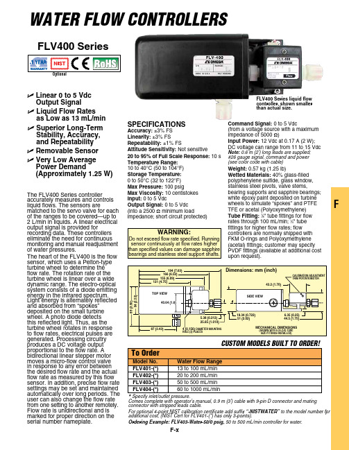
F-xFComes complete with operator’s manual, 0.9 m (3') cable with 9-pin D connector and mating connector with stripped leads cable.For optional 4-point NIST calibration certificate add suffix “-NISTWATER” to the model number fpr additional cost, (NIST Cert for FLV401-(*) has only 3-points).Ordering Example: FLV403-Water-50/0 psig, 50 to 500 mL/min controller for water.FLV400 SeriesU L inear 0 to 5 Vdc Output Signal U L iquid Flow Rates as Low as 13 mL/min U S uperior Long-Term Stability, Accuracy, and Repeatability U R emovable Sensor U V ery Low Average Power Demand(Approximately 1.25 W)The FLV400 Series controller accurately measures and controls liquid flows. The sensors arematched to the servo valve for each of the ranges to be covered—up to 2 L/min in liquids. A linear electrical output signal is provided forrecording data. These controllers eliminate the need for continuous monitoring and manual readjustment of water pressures.The heart of the FLV400 is the flow sensor, which uses a Pelton-type turbine wheel to determine the flow rate. The rotation rate of the turbine wheel is linear over a wide dynamic range. The electro-optical system consists of a diode emitting energy in the infrared spectrum. Light energy is alternately reflected and absorbed from “spokes” deposited on the small turbine wheel. A photo diode detects this reflected light. Thus, as the turbine wheel rotates in response to flow rates, electrical pulses are generated. Processing circuitry produces a DC voltage output proportional to the flow rate. A bidirectional linear stepper motor moves a micro-flow control valve in response to any error between the desired flow rate and the actual flow rate as measured by this flow sensor. In addition, precise flow rate settings may be set and maintained automatically over long periods. The user can also change the flow rate from one setting to another remotely. Flow rate is unidirectional and is marked for proper direction on the serial number nameplate.SPeciFicATiOnSAccuracy: ±3% FS Linearity: ±3% FSRepeatability: ±1% FSAttitude Sensitivity: Not sensitive20 to 95% of Full Scale Response: 10 s Temperature Range: 10 to 40°C (50 to 104°F)Storage Temperature: 0 to 50°C (32 to 122°F)Max Pressure: 100 psigMax Viscosity: 10 centistokes input: 0 to 5 VdcOutput Signal: 0 to 5 Vdc (into a 2500 Ω minimum loadimpedance; short circuit protected)command Signal: 0 to 5 Vdc(from a voltage source with a maximum impedance of 5000 Ω)input Power: 12 Vdc at 0.17 A (2 W); DC voltage can range from 11 to 15 VdcNote: 0.6 m (2') long leads are supplied; #26 gauge signal, command and power (see color code with cable)Weight: 0.57 kg (1.25 lb)Wetted Materials: 40% glass-filled polyphenylene sulfide, glass window, stainless steel pivots, valve stems,bearing supports and sapphire bearings;MecHAnicAL DiMenSiOnS(SHOWn WiTH 6.35 (1/4) TUBeSiZe FiTTingS inSTALLeD)FLV400 Series liquid flow controller, shown smaller than actual size.WaTER FLOW COnTROLLERS。
斯瓦格洛克 比例泄压阀 R 系列 说明书

Propor tional Relief ValvesR Series■ Liquid or gas service■ Set pressures from 10 to 6000 psig (0.68 to 413 bar)■ 1/4 and 1/2 in. and 6 to 12 mm end connectionsProportional Relief ValvesFeaturesHigh-Pressure Valves■ Service up to 6000 psig (413 bar)■ Multiple springs for a selection of set pressure ranges ■ 1/4 in. and 6 and 8 mm end connections—R3A series ■ 1/ in. and 1 mm end connections—R4 seriesLow-Pressure Valves■ Service up to 300 psig ( 0.6 bar)■ One spring for the full set pressure range■ 1/4 in. and 6 and 8 mm end connections—RL3 series ■ 1/ in. and 1 mm end connections—RL4 seriesQuad sealeliminates leakage around stem duringrelief modeEnd connectionsinclude gaugeable Swagelok ® tube fittings and NPT or ISO pipe threadsLabelidentifies set pressure rangeLock wire capability secures cap to maintain set pressure adjustmentO-ringprovides elastomer-to-metal seal for positive shutoff at seat.(Other series use bonded disc. See Materials ofConstruction )Capprovides easy external set pressure adjustment Springadjusts to provide desired set pressureR3A series valve shown.Lock nutmaintains cap position,ensuring set pressure adjustmentApplicationsR series relief valves are proportional relief valves that open gradually as the pressure increases. Consequently, they do not have a capacity rating at a given pressure rise (accumulation), and they are not certified to ASME or any other codes.S ome system applications require relief valves tomeet specific safety codes. The system designer and user must determine when such codes apply and whether these relief valves conform to them.OperationR series relief valves OPEN when system pressure reaches the set pressure and CLOSE when system pressure falls below the set pressure.■ High-pressure R3A and R4 series—select and install thespring that covers the required set pressure; apply the matching label to the cap.■ L ow-pressure RL3 and RL4 series—the spring is alreadyinstalled.F or valves not actuated for a period of time, initialrelief pressure may be higher than the set pressure.Proportional Relief Valves 3 Technical DataPressure-Temperature RatingsBack PressureHigh-Pressure Valves (R3A and R4 Series)The effect of system back pressure is minimized by thedesign of these high-pressure valves.Low-Pressure Valves (RL3 and RL4 Series)System back pressure increases the set pressure of thevalve. To compensate, multiply the back pressure by 0.8 andsubtract the result from the desired set pressure. Use theresult to pre-set the valve while back pressure is equal toatmospheric pressure.Example:Desired set pressure is 1 0 psig. System back pressure is40 psig.Step 1. M ultiply back pressure by 0.8.40 psig 3 0.8 = 3 psig.Step . S ubtract result from desired set pressure.1 0 psig – 3 psig = 88 psig.Step 3. Pre-set proportional relief valve to 88 psig.➀T he pressure-temperature ratings are based upon laboratory testing to ensure that the cracking pressure does not deviate by more than 0 % from the initial room-temperature set pressure.➁ Outlet pressure should not exceed inlet pressure.Oxygen Service HazardsFor more information about hazards and risks of oxygen-enriched systems, see the Swagelok Oxygen System Safetytechnical report, MS-06-13.4 Proportional Relief ValvesMaterials of Construction15141312109875421RL3onlyRL4 only611121617183R3A onlyR4 only5421387610911131212a19R3A RL4RL3R419Wetted components listed in italics.➀ Material Safety Data Sheet for bonding agents available on request.Proportional Relief Valves 5Air Flow, std L/minFlow Data at 70°F (20°C)AirRL3 and RL4 Series RL3RL4RL3 and RL4 SeriesWater Flow, L/minWaterRL3RL46 Proportional Relief ValvesHigh-Pressure Valves (R3A and R4 Series)Low-Pressure Valves (RL3 and RL4 Series)DimensionsDimensions are for reference only and are subject to change.Dimensions shown with Swagelok tube fitting nuts finger-tight.➀ S ee specifications ISO 7/1, BS EN 10 6-1, DIN- 999, and JIS B0 03.Valve with Manual Override HandleProportional Relief Valves 7Options and AccessoriesSeal MaterialsFluorocarbon FKM is the standard seal material. Buna N, ethylene propylene, and neoprene are available. To order a valve with an optional seal material, add a valve seal material designator to the valve ordering number.Examples: S S-4R3A -BUSS-RL3S4-BUTo order a replacement seal kit, insert a seal kit material designator as a prefix (R3A series) or suffix (all others) to the seal kit basic ordering number.Examples:B U -R3A-K SS-3K-RL3-BNOrdering InformationLow-Pressure Valves (RL3 and RL4 Series)Valve contains spring; set pressure must be adjusted. Selecta valve ordering number.Spring KitsSpring kits include spring and installation instructions. Select a spring kit ordering number.High-Pressure Valves (R3A and R4 Series)Valve does not contain spring. Select a valve ordering number and a spring kit ordering number.Spring KitsSpring kits include spring, label, 30 SS lock wire with seal, spring support, and installation instructions.Select a spring kit basic ordering number and add the spring designator for the desired set pressure range.Examples:177-R3A-K1-F 177-13K-R4-CSpecial Cleaning and Packaging (SC-11)To order R series relief valves processed in accordance with Swagelok Special Cleaning and Packaging (SC-11), MS-06-63, to ensure compliance with product cleanliness requirements stated in ASTM G93 Level C, add -SC11 to the valve ordering number.Example: SS-RL3S4-SC11Manual Override HandlesA manual override handle opens the valve without changing the set pressure.For use with:■ RL3 and RL4 series—standard spring■ R3A series—A, B, and Csprings only■ R4 series—A spring only.Handle diameter is 1.50 in. height of valve with handle in closed position:■ 5.16 in. (131 mm) for R3Aand RL3 series■ 6.78 in. (17 mm) for R4and RL4 series.To order, add -MO to the valve ordering number.Example: SS-RL3S4-MOManual Override Handle KitsKits contain handle, pull rod, spring support, and instructions. To order, select the desired kit ordering number.316 SS spring support316 SS pull rodPhenolic handle SeriesManual Override Kit Ordering Number RL3, R3A SS-R3A-K5RL4, R4SS-R4-K5➀ Use BU for R3A series seal kits.Safe Product SelectionWhen selecting a product, the total system design must be considered to ensure safe, trouble-free performance. Function, material compatibility, adequate ratings,proper installation, operation, and maintenance are the responsibilities of the system designer and user.Warranty InformationSwagelok products are backed by The Swagelok Limited Lifetime Warranty. For a copy, visit or contact your authorized Swagelok representative.Swagelok—TM Swagelok Company© 001, 00 , 003, 004, 005, 006, 007, 008Swagelok Company Printed in U.S.A., MI October 008, R10MS-01-141S wagelok proportional relief valves should never beused as code safety relief devices.Swagelok proportional relief valves are not “SafetyAccessories” as defined in the Pressure Equipment Directive 97/23/EC.。
尼克尔铅皮 brass 推动连接ittings 对工业应用系统 LF3200 Legris说明书
nickel-plated brass push-to-connect fittings for industrial applicationssystem LF3200Legris has put its years of experience as a leader in the connection market into the development of this performing brass push-to-connect forged fitting. The LF3200 rangeprovides pneumatic connections in aggressive applications and harsh environments.LF3200 is suitable for compressed air (lubricatedor non-lubricated). The fitting is designed to perform in particularly harsh (e.g. weld-splatter) or abusive(e.g. steel-toed boot) environments. Tubing compatibility:Polyurethane and Nylon. Metal tubing may be used with specific preparation.Chemical Nickel-Plating:For applications where the fitting is exposed to aggressive environments, better plating is required. Legris uses high phosphorous electroless nickel-plating for the LF3200 fitting range.The electroless nickel-plating has a dull, flat finish. Itadheres to more of the surface, such as in the root of the threads and grooves of the collet. It has better resistance to water, harsh detergents and other aggressive fluids and environments. As a result, the LF3200 series offers superior chemical, corrosion and abrasive resistance.principle of system LF3200All items in the LF3200 range are SILICONE FREEsuitable fluids compressed air up to 290 psi5˚F to 180˚Fworking pressure working temperaturematerials of constructionmaximumtightening torque for LF3200fittings:This depends on the nature and thickness of the tube, surrounding temperature and that of the fluid used.technical specificationselectroless nickel-platedbackup washernitrile ”O “ ringcompatible with nylon and polyurethanecompatible with stainless steel and copper tubing (when grooved p/n 3800 70 00)electroless metal (nickel-plated brass)release buttonelectroless nickel-plated brass bodybody:electroless nickel-plated brass“O” ring:nitrilebackup washer: electroless nickel-plated brass base:electroless nickel-plated brass with thread sealant on tapered components in. lb1370100250308thread sealant on tapered componentsUNF 1/8"1/4"3/8"1/2"UNF &NPT thread C2resistance to aggressive environments and fluidstried and tested technologycompatible tubingadvantages system LF3200for compressed air•instant manual connection and disconnection – no tools required•semi-rigid nylon •flexible polyurethane•high phosphorous electroless nickel-plating •all nickel-plated construction- body - push button - base- backup washerindustrial applications•LF3200 is suitable for many applications such as:- robotics- packaging equipment/machines - textile machinery- semi-conductor equipment - auto process (within auto industry)- pulp and paper - printingC3applicationsC432153209327532083203329832933206320232043216the complete range of LF3200 push-to-connect fittingstaper Page C6taper Page C7taper Page C6taper Page C8taper Page C8UNFPage C8UNFPage C8Page C9Page C9Page C9threaded fittings tube to tube fittings Page C93266Page C93299UNFPage C73201UNFPage C6C5C63215female connector 3275male connector — 3201male connector —C73209male elbow — fractional inch 3299male elbow — fractional inchC83293male run tee — fractional inch 3298male branch tee —32083203male branch tee —male run tee — fractional inchC93216bulkhead connector —fractional inch tube to tube3206straight union —fractional inch3202union elbow —fractional inch3204union tee —fractional inch3266plug-in reducer —tube to tube fittingsnickel-plated brasspush-to-connect fittings for liquid, gas and food processingindustry system LF3600Legris, inventors of the push-to-connect fitting, have earned a reputation as the leading specialist in push-to-connect fitting technology. Legris has employed over 30 years of experience in the research and development of the LF3600 range. LF3600extends Legris ‘know-how’ from pneumatics to other industrial-applications.The principle of the connection is the same. Instant manual connection and disconnection. No need for special tools.Made of nickel-plated brass and fitted with a FKM ”O“ ring protected by a washer, LF3600 forged fittings may be used with all liquid and gaseous fluids compatible with these components, materials and temperatures up to 250°F (depending on the tube material).Chemical Nickel-Plating:For applications where the fitting is exposed to aggressive environments, better plating isrequired. Legris uses high phosphorous electroless nickel-plating for the LF3600 fitting range.The electroless nickel-plating has a dull, flat finish. It adheres to more of the surface, such as in the root of the threads and grooves of the collet. It has better resistance to water, harsh detergents and other aggressive fluids and environments. As a result, the LF3600 series offers superior chemical, corrosion and abrasive resistance.All materials, seals, and plating can come in contact with food.For the quality and cleanliness of the LF3600 products, they are placed in sealed bags inside a Legris box.nickel-plated brass backup washerFKM ”O “ringspring colletcompatible with nylon polyurethane, polyethyleneand FEP 140 tubingworking temperatureAll items in the LF3600 rangeare SILICONE FREEThis depends on the nature and thickness of the tube, on surrounding temperature and that of the fluid used.technical specificationfrom -4°to 250°F . The allowable working temperature depends on the type of tube used.working pressure7 to 290 psi. The maximum pressure of the circuit depends on the type of tube used.suitable fluidsall liquids and gases compatible with the materials of the fitting.Examples: food fluids, cleaning/cold & hot water, steam, oils …materialsof constructionmaximumtightening torque for LF3600 fittings,BSPP threads and M5:(with 0602 sealing washer)nickel-plated brass bodyM5G1/8"G1/4"G3/8"G1/2"x 0.81470100266300principle of system LF3600for liquids and gasesparallel threadin. lb D2compatible with stainless steel and copper tubing (when grooved p/n 3800 70 00)body:high phosphorus FDAchemical nickel-plated brassbackup washer:high phosphorus FDAchemical nickel-plated brassspring collet:high phosphorus FDAchemical nickel-plated brass“O” ring:FKM (FPM) fluoroelastomerconforming to FDA standardbase:high phosphorus FDAchemical nickel-plated brass Thread sealant does not come on these products. This is so that the appropriate sealant for the application can be applied.close spacing of LF3600 productsadvantages of system LF3600for liquids and gases5/321/8.575/321/4.691/41/8.631/41/4.691/43/8.793/81/4.833/83/8.893/81/2 1.001/23/8.931/21/2 1.00C L min NPT in ØD inD3increased performance•excellent resistance to abrasion and corrosion due to high phosphorus chemical nickel-plating individually deposited on brass components.•working temperature from –4°to + 25°F due to “all metal ”components (except o-ring)•full flow fluid passage , minimal pressure drop•automatic sealing of BSPP and metric versions via a captive seal at base•backup washer protects the o-ringwide range•multiple configurations and accessories•from 5/32" to 1/2" O.D. and 4mm to 14 mm O.D.•NPT, BSP taper, BSP parallel and metric threads •ideal for many types of tubing •inch to metric tube adapterscompactness and aestheticsEach model has been redesigned to meet all requirements :•compactness due to small overall dimension s with inter-connectability for configurations pictured above •aesthetic with modernized external shapestime saving connection and disconnection•instant manual connection and disconnection •easy installationnumerous applications•suited to many industries including the food industry :-numerous suitable fluids (food fluids, cleaning / hot and cold water, steam, oil …)- components and chemical nickel coating conforming to FDA standardOur production process includes individual unit quality control and dating,for all LF 3600 push-to-connect fittings, in order to guarantee their quality and traceability.system LF3600 for liquids and gasesD43675360136813614360936693629360036993608360336983693360636023604361636363639366636683667312236203126the complete range of LF3600 push-to-connect fittingstaper Page D6UNF , parallel and metric Page D7metric Page D7parallel and metric Page D7taper Page D8parallel Page D8taper Page D8Page D9UNF , parallel and M5Page D9taperPage D10taperPage D10UNF , parallel and metric Page D11UNF , parallel and metric Page D11Page D12Page D12Page D12threaded fittings tube to tube fittingsPage D13parallel Page D13Page D13bulkhead connectors Page D14Page D14Page D14Page D15Page D153120Page D15Page D153626Page D15accessories D53621taper Page D63631parallel and metric Page D73618banjo bodyparallel and metric Page D113622Page D15D63675male connector —3675male connector —3621male stud standpipe — metric tube to BSPTYou will also find the LF 3600 push-to-connect fittings on the on-line catalog of our web site for both inch and metric tubes. ’s advantage pointsD7360136813614male connector —male connector —female connectorfractional inch= suitable for food applications3631male standpipe —D8360936693629male elbow — metric extended male elbow extended male elbow 3609male elbow — fractional inch = suitable for food applicationsD936993600male elbow — tube to UNF, BSPP or M5If the nylon sealing washers are incompatible with the application, system LF3600 may be used with copper washer 0138.Details on this washer can be found in the Accessories section of this catalog, section H.cartridgePlease contact us to discuss the choice of material into which the cartridge will be inserted.The use of this cartridge•avoids the need to cut threads •permits the part to be press fitted•enables instant tube connection and disconnectionfractional inch36990420IdentificationPart numbers have been chosen by a method of mnemonics.Each LF3600 fitting is identified by: •product type•the outside diameter of the tube •the thread code or second tube O.D.Example of numbering systemproducttypethread code or second tube O.D.tube O.D.= suitable for food applicationsD1036033608male branch tee —male run tee — fractional inch tube to tube to NPT3608male branch tee —3603male run tee — metric36983693male branch tee —male run tee — tube to tube to UNF, BSPP or M5fractional inch360636023604tube to tube fittingsstraight union — metric union elbow — metric union tee — metric 3606straight union — fractional inch 3602union elbow — fractional inch 3604union tee — fractional inch361636363639bulkhead connectorsbulkhead connector 3616bulkhead connector female bulkhead connector bulkhead elbow —Fittings will orientate about the body for positioning purpose.366636683667This catalog includes details of a range of brass accessories compatible with LF3600.Please refer to the Accessories section H.plug-in reducer — metricplug-in expander — metricplug-in — metric /inch adapterLF3600 push-to-connect fittings allow connection with various types of tubing presented in this catalog:•flexible polyurethane tube 1/8" to 1/2" O.D. – page M114mm to 14mm O.D. – page M13•low density polyethylene 1/8" to 1/2" O.D. – page M154mm to 12mm O.D. – page M15•fluoropolymer FEP140 tube 1/8" to 1/2" O.D. – page M164mm to 12mm O.D. – page M16•semi-rigid nylon tube1/8" to 1/2" O.D. – page M74mm to 14mm O.D. – page M936203626double male unionplug —metric3120double male unionDimensions for ØD2 are I.D. of the tube.*nickel-plated brass3122barbed connector3126plug —fractional inch3622plug-in barbed connector。
Parflex Rapid Assembly Fitting System 快速连接套接件系统说明书
Parflex Rapid Assembly Fitting SystemPlug and Play with Quick ConnectThe Parflex Rapid Assembly (RA) quick connect fittings offer plug and play convenience in a very compact, economical system. RA fittings, from Parker's Parflex division, consists of Parker 56 Series RA quick-connecting hose fittings, one adapter and any Parflex hose rated to 3,000 psi @ 212°F.This system offers the advantages of reduced tools needed for equipment plumbing. Installation of the hose assembly does not require wrenches or routing orientation, thereby reducing plumbing time and improving productivity.Since Parflex 56 RA fittings are not live swivels, care should be taken to insure that relative move-ment between the adapter and the hose fitting is eliminated. Sealing is achieved through the use of petroleum and synthetic hydraulic oil resistant elastomeric o-rings.2Parker Hannifin Corporation | Parflex Division | Ravenna, Ohio | /pfdParflex Rapid Assembly FittingsQuick Connect Fittings For Thermoplastic HoseTight pilot line and joystick routings require significant installation time and can be a bottle neck in the assem-bly process. 100R1 rubber hose does not fit in the tight channels from the operator compartment to the valves. Several special tools are required to install the elbow adapter fittings at the build up stations and different sized wrenches arerequired on the assemblyline.Parflex 510D and 518D pilot lines, with Rapid Assembly fittings on the unit, eliminate elbow adapters at the build up station so all the adapt-ers can be installed with nut runners. Routing hose becomes much easier because of the low profile hose O.D., very small mini-mum bend radius and low coeifficent jacket.Connecting hose with thenew fittings reduces instal-lation time and eliminatesthe need for tools.This twinline 510D formed hose uses the 56 Series Rapid Assembly Fittings for sizes -4 and -6 that were developed for applications needing a quick connection.3Parker Hannifin Corporation | ParflexDivision | Ravenna, Ohio | /pfdRapid Assembly Fittings Create SavingsMoney, Space & FreightWatch the VideoOne Fitting, One Adapter, One Hose Parflex thermoplastic hoses, qualified with 56 Series Rapid Assembly Fittings feature a reduced O.D. and tighter bend radius that can transport the same flow capacity as hoses with larger outside diameters. Typically, Parflex 518D and 510D hose has at least an 1/8" smaller diameter than a standard 100R7 rubber hose. In addition, the Parflex hose is up to 5x lighter than comparable hoses.Parflex thermoplastic hoses are exceptionally suited for routing through tight spaces whilemaintaining flexibility. In fact, flexibility is one of the key fea-tures of these medium pressure hoses.Compact hoses, (510D, 518D, 563TJ, 563LT), are often used in pilot lines or joy stick applica-tions where multiple hoses are required to fit into a tight space. They can formed during produc-tion to fit the specific application design.Compact wire reinforced hoses, such as 563TJ/LT (100R17), canalso benefit from the use of a quick connect fitting in applica-tions where multiple hoses are required to fit into a tight space. The smaller outside diameter of the hose and lower profile fit-tings contribute to space sav-ings and reduced shipping costs. Not just the shipping costs from Parflex to you, but also from you to your customer.• Compact • Light weight• Quick connecting fittings • No tools needed• Improved assembly time • Reduced system weight • Easy routing• Exceptional kink resistance • DurableProduct Features:4Parker Hannifin Corporation | Parflex Division | Ravenna, Ohio |/pfdLegend F - Fiber H - Copolyester N - NylonU- PolyurethaneR - Smooth Synthetic RubberUTJ - TOUGHJACKET™ PolyurethaneParflex Rapid Assembly FittingsHoses Available for the Plug and Play System5Parker Hannifin Corporation | Parflex Division | Ravenna, Ohio | /pfdView standard 56 Series Fitting s next page u1WW56 Male Rapid Assembly 45º ElbowConstruction: Steel.Nitrile O-ring.1WY56 Male Rapid Assembly 90º ElbowConstruction: Steel.Nitrile O-ring.1WU56 Male Rapid Assembly StraightConstruction: Steel.Nitrile O-ring.685RA Adapter Female Rapid Assembly - Male SAE Straight Thread ORBConstruction: Steel. Nitrile O-ring.Parflex Rapid Assembly Fittings56 SeriesParflex 56 Series Fittings Permanent Crimp FittingsToughShield Plus, featuring Parker's Zinc Nickel Plating Standard, protects againstcorrosion, improving the performance of crimp hose fittings in harsh hydraulicenvironments, reducing both downtime and warranty costs.*6Parker Hannifin Corporation | Parflex Division | Ravenna, Ohio | /pfd7Parker Hannifin Corporation | Parflex Division | Ravenna, Ohio | /pfdParflex 56 Series FittingsPermanent Crimp Fittings4660-Rapid-Assembly 1/23 © 2022-2023 Parker Hannifin Corporation - All Rights ReservedParker Hannifin CorporationParflexParflex Division1300 North Freedom St.Ravenna, OH 44266phone (330) 296 2871fax (330) 296 8433/parflex。
FITOK卡套-01
T ube Fittings, T ubes and Pipes6 SeriesValves and Fittings FF0120409ContentsFITOK Stainless Steel Seamless T ubing081214FITOK Stainless Steel Seamless PipeMale ConnectorsBulkhead Male Connectors25Thermocouple Connectors26Female Connectors27Bulkhead Female Connectors32Unions33Conversion Unions34Reducing UnionsBulkhead Unions3436Bulkhead Reducing Unions37Bulkhead Locknuts3638Male Elbows41o45Male Elbowso45 Adjustable Male Elbows4445Union Elbows46Union Reducing Elbows47Adjustable Male Branch T ees50Adjustable Male Run T ees51Female Branch T ees5242Adjustable Male ElbowsBulkhead Conversion Unions37Male Branch T ees48Male Run T ees49ContentsReducing Union T ees55Union Crosses57Caps57Female Run T ees53Union T ees54Plugs58Vent Protectors58Lapped Flange Connectors58Nuts59Knurled Nuts59Male Nuts59Front Ferrules60Rear Ferrules60Reducer Elbows64Nuts + Ferrules60Reducers62Bulkhead Reducers64Insert for Soft Plastic T ubings65Nut-Ferrule Sets61Ferrule Sets61T echnical DataContentsFeatures◎ Thread EndsNPT Threads (NPT)◎ ◎ Comply with ASME B1.20.1, SAE AS71051.Installation torque complies with UL 842.o □ 60 thread angle □ Pitch measured in inch□ Truncation of root and crest are parallel □ T aper 1:16□ Type of sealing:thread sealantWorking pressure are based on ANSI/ASME B31.3 at ambient temperature.◎ ◎ ◎ ◎ ◎ ◎ ◎ ◎Sizes range from 1/16" to " and 2 mm to 38 mm.Diverse materials and configurations are available.Precision machined components ensure perfect deformation ofthe ferrules and tubing.Hardened threads with smooth surface finish avoid galling andhelp to extend the fitting service life.Female nut threads are silver-plated to reduce the friction againstthe body threads.Radius junction design with elbows provides smooth flow path.Every fitting is stamped with size, material, and heat code.Fittings are easy to disconnect and retighten.1 1/21Dielectric Fittings80RS Gaskets81RP , RG, RJ Gaskets82O-Rings83Female Adapters72Flange Adapters76Weld Connectors77Weld Elbows78Automatic T ube Weld Connectors79Calibration Fittings79Port Connectors65Reducing Port Connectors66Male Adapters67ISO T apered Threads (R, R1, R2, Rc, RT , PT , BSPT , ZG)◎ ◎ Comply with ISO 7-1, EN 10226-1, BS 21, DIN 2999, JIS B0203.The installation torque is the same as that of NPT thread ends.o □ 55 thread angle □ Pitch measured in inch□ Truncation of root and crest are round □ T aper 1:16□ Type of sealing: thread sealantISO Parallel Threads (G, RP , PF , BSPP)Comply with ISO 228-1, DIN ISO 228-1, JIS B0202, BS 2779. 3. PP Stud End and RP Port□ RP port complies with DIN 3852-2 type X 4. RG Port, RG Gasket and BP Stud End□ RG port complies with EN 837-1/3□For RG gasket, see page 82SAE/MS Threads (UN, UNJ)Straight Comply with ASME B1.1, SAE J475, ISO R725.o □ 60 thread angle □ Pitch measured in inch□ Truncation of root and crest are parallelWorking Pressures of ISO T apered Thread Endso □ 55 thread angle □ Pitch measured in inch□ Truncation of root and crest are round2. RP Stud End, RP Gasket and RP Port□ RP studs end complies with DIN 3852-2 type B□ For RP gasket, see page 82□ RP port complies with DIN 3852-2 type X□ RS stud end complies with DIN 3852-2 type A□ For RS gasket, see page 81□ RP port complies with DIN 3852-2type XThe RP gasket can be used with a RS fittingThe working pressures of ISO tapered thread ends are the same with that of the NPT thread ends.3Types of Sealing for ISO parallel threads1. RS Stud End, RS Gasket and RP Port1. ST Stud End and ISO 11926-1 Port□ □ 83ST stud end complies with ISO 11926-3For O-ring, see page 2. 37° Flare (AN) Stud and Flared Tubing□ The type of sealing complies with SAE J514Working pressures are based on ISO 11926-3 at ambient temperature.o□ 60 thread angle □ Pitch measured in mm□ Truncation of root and crest are parallelMetric Threads (M)Comply with ISO 261.□ 3852-1 type A□ RS -M gasket ,MRS stud end complies with DIN 81For see page 3. MST Stud End and ISO 6149-1 Port□ MST stud end complies with ISO 6149-3□ For O-r ing,83see page 2.MS Stud End, RG-M gasket and MS PortG□ R -M gasket ,82For see page 1. MRS Stud End, RS-M gasket and MS Port1. Working Pressures for MRS/MS Stud End and MS Port2. Working Pressures for MST Stud EndsWorking Pressures of Metric Thread Ends ◎ Working T emperaturesTube Ends5The working temperatures of the thread ends may be limited by the teflon tape or thread sealant or , when applicable, the gaskets or O-rings as follows:Thread EndsTypes of Sealing for SAE/MS threads Types of Sealing for Metric Threads Working pressures are based on ISO 6149-3 at ambient temperature.MaterialsOrdering InformationExample:1. Male connector with 1/4" Tube, 1/4 NPT thread and 316 stainless steel material, the complete ordering number is SS-CM-FL4-NS4.2. Female adapter with 12 mm tube, 1/4 RG thread and brass material, the complete ordering number is B-AF-MT12-RG4.Installation Instructions3/41/21/41 1/401Fig.1Fig.23/41/21/4Cautions:◎ Working Pressures7◎◎◎◎ FITOK tube fittings up to 1" or 25 mm1. Loosen the nut 1/4 turn from finger-tight position.2. Insert tubing into the tube fitting, make sure that the tubing rests firmly on the shoulder of the port.3. Finger-tighten the nut.4. Tighten the nut 1 1/4 turns with wrench while holding steady the body of the fitting or the valve (Fig.1). For small-sized fittings (1/16", 1/8" and 3/16", 2 mm, 3 mm and 4 mm), tighten the nut 3/4 turn with wrench (Fig.2). FITOK tube fittings over 1" or 25 mm1. Use presetting tool to install the ferrules onto the tube, please refer to the instruction of Hydraulic Presetting T ool for details.2. Insert the preset tubing with ferrules and nut into the body of fitting, finger tight.3. Tighten the nut one-half turn with wrench. Reinstallation (all sizes)1. Mark on the nut and body before disassembling the fitting.2. Tighten the nut to the marked location before reinstallation.3. Tighten the nut slightly with wrench. Plugs and Port Connectors1.Tighten the plug or port connector 1/4 turn from the finger-tight position while holding steady the body of the fitting. For small-sized fittings (1/16", 1/8" and 3/16", 2 mm, 3 mm and 4 mm), tighten the nut 1/8 turn with wrench .2.Reinstallation: Tighten slightly with a wrench from the finger-tight position.The Installation Instructions of the tube adapter end of Port Connectors are the same as the FITOK Tube Fittings.◎◎◎◎◎◎◎◎◎◎◎ Do not loosen or tighten fittings when system is pressurized. Make sure that the tubing rests firmly on the shoulder of the port. Always leave enough straight length of the tubing for the fittings. Always use an insert for extremely soft plastic tubing.Material of the metal tubing should be softer than that of the fitting. For example, stainless steel tubing should not be used with brass fittings. When tubing and fittings are made of the same material, the tubing must be fully annealed.The allowable working pressure of the tube fitting is rated to the maximum working pressure of the corresponding tubing, which can be found in FITOK tubing data sheet. For those which can not be found in FITOK tubing data sheet, please contact the authorized representative or FITOK for related information. Keep the tubing end and surface clean and smooth.Always use proper thread sealants on tapered pipe threads. Make sure that its working temperature does not exceed that of the the sealants.When assemble the tube fitting, hold the body with a wrench and turn the nut instead of holding the nut. When install a valve with tube fitting end, hold the valve body with a wrench and turn the nut.When assemble the fitting to a valve with thread, hold the valve body with a wrench and turn the body of the fitting.◎ ◎ ◎ ◎ The maximum working pressure of t tubing data.The maximum working pressure of the thread ends at ambient temperature are stated above.T o get the maximum working pressure at elevated temperature, use the maximum working pressure at ambient temperature to multiply the factors in the form of Elevated T emperature Factors in page 9.The whole fitting is rated by the smallest value among its ends.he tube ends at ambient temperature are rated by the used FITOK tubings. Refer to FITOK ◎ Add material designator as a prefix to the basic ordering number to get the complete ordering number.◎ T o order fittings with special cleaning and packaging (FC-02), following ASTM G93 C standard, add -F2 as a suffix to the ordering number. Example: SS-LM-ML8-NS4-F2.FITOK Stainless Steel Seamless TubingFeatures◎ ◎ ◎ Sizes range from 1/16" to 1 1/2" and 3 mm to 38 mm.Material, size, specification and heat code are indicated on the tubing surface.Pickling surface finish and mechanical polished surface finish tubes are available.Material StandardsAllowable Working PressureFractional TubingMetric Tubing9◎ ◎ ◎ The allowable working pressures in the table below for fractional tubing and metric tubing are based on ASME B31.3 at ambient temperature.The data in the table are applied to 316 SS, 304 SS and 321 SS. For 316L SS and 304L SS, multiply the data in the table by 0.84 to get the allowable working pressure.T o work out the allowable working pressure at elevated temperature, take allowable working pressure at ambient temperature to multiply the factors in the table of Elevated T emperature Factors in page 9.Elevated T emperature FactorsExample to calculate the allowable working pressure:Type 316L SS 12 mm O.D.×1.5 mm wall at 800°F (427°C)1. The allowable working pressure for 316 SS at ambient temperature is 333 bar (shown in the table above), multiply by 0.84 to get 316L SS data. So allowable working pressure for 316L SS at ambient temperature is 333 bar × 0.84 = 280 bar.2. The elevated temperature factor for 800°F (427°C) is 0.74 (shown in the table above). So the allowable working pressure for 316L SS 12 mm O.D. × 1.5 mm wall at 800°F (427°C) is 280 bar × 0.74 = 207 bar.11Metric TubingAdd the actual length (foot or meter) and surface finish code as a suffix to the basic ordering number to get the complete ordering number. "AP " for pickling surface finish, "MP " for mechanical polished surface finish.Ordering InformationFractional Tubing For example:1. 12 feet long, outside diameter 1/2", wall thickness 0.049", and pickling surface finish 316L SS seamless tube, the complete ordering number is 6L-ST8-049-12-AP .2. 3 meters long, outside diameter 1/2", wall thickness 0.049", and mechanical polished surface finish 316L SS seamless tube, the complete ordering number is 6L-ST8-049-3M-MP .3. 3 meters long, outside diameter 12 mm, wall thickness 1.0 mm, and pickling surface finish 304L SS seamless tube, the complete ordering number is 4L-ST12M-1.0-3M-AP .13P i p e D i m e n s i o nFITOK Stainless Steel Seamless PipeFeatures◎◎ Nominal pipe sizes from NPS 1/8 to NPS 2. Material, size, specification and heat code are indicated on the pipe surface.Allowable Working PressureOrdering InformationAdd the actual foot (feet)/meter (meters) as a suffix to the basic ordering number to complete the ordering number.Example:1. 12 feet long, NPS 1/2, schedule number 40S, 316 SS seamless pipe, the complete ordering number is SS-SP8-40S-12. 2. 2 meters long, NPS 1/2, schedule number 40S, 316 SS seamless pipe, the complete ordering number is SS-SP8-40S-2M.Material StandardThe allowable working pressures in the form are based on ASME B31.3 at ambient temperature.The data in the form are applied to 316 SS, 304 SS and 321 SS. For 316L SS and 304L SS, multiply the data in the form by 0.84 to get the allowable working pressure. The elevated temperature factors are the same with those of FITOK stainless steel seamless tubing.◎◎◎Male Connectors14151/81/81/81/41/41/41/43/83/83/83/81/21/21/23/43/41111/81/43/81/81/43/81/21/81/43/81/21/43/81/21/23/41/23/41-CM-FL2-RS2-CM-FL2-RS4-CM-FL2-RS6-CM-FL4-RS2-CM-FL4-RS4-CM-FL4-RS6-CM-FL4-RS8-CM-FL6-RS2-CM-FL6-RS4-CM-FL6-RS6-CM-FL6-RS8-CM-FL8-RS4-CM-FL8-RS6-CM-FL8-RS8-CM-FL12-RS8-CM-FL12-RS12-CM-FL16-RS8-CM-FL16-RS12-CM-FL16-RS1630.035.336.332.337.638.944.737.839.140.446.242.743.249.049.052.955.557.759.97.111.211.27.111.211.214.27.111.211.214.211.211.214.214.215.714.215.718.312.712.712.715.215.215.215.216.816.816.816.822.922.922.924.424.431.231.231.22.32.32.34.04.84.84.84.05.97.17.15.97.910.411.915.711.916.019.811.111.111.114.314.314.314.317.517.517.517.522.222.222.228.628.638.138.138.114.319.122.214.319.122.227.015.919.122.227.020.622.227.027.033.334.934.941.313.718.021.813.718.021.825.913.718.021.825.918.021.825.925.932.025.932.039.11/81/81/41/41/41/45/165/163/83/83/83/83/81/21/21/21/25/83/43/4111/81/41/81/43/81/21/81/41/81/43/81/23/41/43/81/23/41/23/413/41-CM-FL2-RT2-CM-FL2-RT4-CM-FL4-RT2-CM-FL4-RT4-CM-FL4-RT6-CM-FL4-RT8-CM-FL5-RT2-CM-FL5-RT4-CM-FL6-RT2-CM-FL6-RT4-CM-FL6-RT6-CM-FL6-RT8-CM-FL6-RT12-CM-FL8-RT4-CM-FL8-RT6-CM-FL8-RT8-CM-FL8-RT12-CM-FL10-RT8-CM-FL12-RT12-CM-FL12-RT16-CM-FL16-RT12-CM-FL16-RT1630.535.632.837.838.444.734.038.635.339.939.946.247.843.443.449.050.549.050.557.257.462.29.714.29.714.214.219.19.79.79.714.214.219.119.114.214.219.119.119.119.123.919.123.912.712.715.215.215.215.216.316.316.816.816.816.816.822.922.922.922.924.424.424.431.231.22.32.34.84.84.84.84.86.44.87.17.17.17.17.19.710.410.411.915.715.715.722.411.111.114.314.314.314.315.915.917.517.517.517.517.522.222.222.222.225.428.628.638.138.111.114.312.714.317.522.214.314.315.915.917.522.227.020.620.622.227.023.827.034.934.934.91/161/161/161/81/81/81/81/83/163/163/161/41/41/41/41/41/45/165/165/165/163/83/83/83/83/83/81/21/21/21/21/21/25/85/85/85/83/43/43/43/47/87/87/81111 1/81 1/41 1/41 1/21/161/81/41/161/81/43/81/21/161/81/41/161/81/43/81/23/41/81/43/81/21/81/43/81/23/411/81/43/81/23/411/43/81/23/43/81/23/411/23/411/23/41111 1/41 1/2Male Connectors-CM-FL1-NS1-CM-FL1-NS2-CM-FL1-NS4-CM-FL2-NS1-CM-FL2-NS2-CM-FL2-NS4-CM-FL2-NS6-CM-FL2-NS8-CM-FL3-NS1-CM-FL3-NS2-CM-FL3-NS4-CM-FL4-NS1-CM-FL4-NS2-CM-FL4-NS4-CM-FL4-NS6-CM-FL4-NS8-CM-FL4-NS12-CM-FL5-NS2-CM-FL5-NS4-CM-FL5-NS6-CM-FL5-NS8-CM-FL6-NS2-CM-FL6-NS4-CM-FL6-NS6-CM-FL6-NS8-CM-FL6-NS12-CM-FL6-NS16-CM-FL8-NS2-CM-FL8-NS4-CM-FL8-NS6-CM-FL8-NS8-CM-FL8-NS12-CM-FL8-NS16-CM-FL10-NS4-CM-FL10-NS6-CM-FL10-NS8-CM-FL10-NS12-CM-FL12-NS6-CM-FL12-NS8-CM-FL12-NS12-CM-FL12-NS16-CM-FL14-NS8-CM-FL14-NS12-CM-FL14-NS16-CM-FL16-NS8-CM-FL16-NS12-CM-FL16-NS16-CM-FL18-NS16-CM-FL20-NS16-CM-FL20-NS20-CM-FL24-NS2423.926.231.029.730.535.635.842.231.231.236.332.832.837.838.444.746.234.038.639.145.535.339.939.946.247.847.038.943.443.449.050.557.244.244.249.050.545.750.550.557.250.550.557.257.457.462.262.277.277.288.99.79.714.29.79.714.214.219.19.79.714.29.79.714.214.219.119.19.79.714.219.19.714.214.219.119.123.99.714.214.219.119.123.914.214.219.119.114.219.119.123.919.119.123.919.119.123.923.923.923.926.28.68.68.612.712.712.712.712.713.713.713.715.215.215.215.215.215.216.316.316.316.316.816.816.816.816.816.822.922.922.922.922.922.924.424.424.424.424.424.424.424.425.925.925.931.231.231.231.241.141.150.01.31.31.32.32.32.32.32.32.33.03.03.04.84.84.84.84.84.86.46.46.44.87.17.17.17.17.14.87.19.710.410.410.47.19.711.912.710.411.915.715.711.915.718.311.915.722.422.422.427.734.07.97.97.911.111.111.111.111.112.712.712.714.314.314.314.314.314.315.915.915.915.917.517.517.517.517.517.522.222.222.222.222.222.225.425.425.425.428.628.628.628.631.831.831.838.138.138.146.047.647.657.27.911.114.311.111.114.317.522.211.111.114.312.712.714.317.522.227.014.314.317.522.215.915.917.522.227.034.920.620.620.622.227.034.923.823.823.827.027.027.027.034.930.230.234.934.934.934.941.344.544.554.01. Dimensions are for reference only, subject to change.2. Dimensions shown are in finger-tight position.1/41/27/16-203/4-16-CML-FL4-ST7-CML-FL8-ST1257.476.59.111.215.222.94.810.414.322.214.322.2Male Connectors1/161/81/83/161/45/163/83/81/25/83/411/81/81/43/161/45/161/43/81/25/83/41-CM-FL1-AN2-CM-FL2-AN2-CM-FL2-AN4-CM-FL3-AN3-CM-FL4-AN4-CM-FL5-AN5-CM-FL6-AN4-CM-FL6-AN6-CM-FL8-AN8-CM-FL10-AN10-CM-FL12-AN12-CM-FL16-AN1627.232.335.133.537.638.439.639.646.049.053.361.511.411.414.012.214.014.014.014.116.719.321.923.18.612.712.713.715.216.216.816.822.824.524.431.21.31.52.32.34.35.84.37.19.912.315.521.37.911.111.112.714.315.917.517.522.225.428.638.111.111.112.711.112.714.315.915.920.623.828.634.91/161/83/161/45/163/81/23/415/16-245/16-243/8-247/16-201/2-209/16-183/4-161 1/16-121 5/16-12-CM-FL1-OST5-CM-FL2-OST5-CM-FL3-OST6-CM-FL4-OST7-CM-FL5-OST8-CM-FL6-OST9-CM-FL8-OST12-CM-FL12-OST17-CM-FL16-OST2126.732.834.338.440.642.446.052.358.28.68.69.710.411.211.911.914.214.28.612.713.715.216.316.822.924.431.21.32.33.04.86.47.110.415.722.47.911.112.714.315.917.522.228.638.114.314.315.919.122.223.828.638.144.514.014.015.718.821.823.628.437.844.21/81/41/43/83/83/81/21/81/81/41/43/81/21/2-CM-FL2-ONS2-CM-FL4-ONS2-CM-FL4-ONS4-CM-FL6-ONS4-CM-FL6-ONS6-CM-FL6-ONS8-CM-FL8-ONS832.835.138.439.941.447.049.87.17.19.79.710.413.513.58.615.215.216.816.816.822.92.34.84.87.17.17.110.411.114.314.317.517.517.522.219.119.123.823.828.633.333.318.818.823.623.628.433.033.01/81/81/41/41/21/23/43/411/81/41/81/43/81/21/23/41-CM-FL2-RP2-CM-FL2-RP4-CM-FL4-RP2-CM-FL4-RP4-CM-FL8-RP6-CM-FL8-RP8-CM-FL12-RP8-CM-FL12-RP12-CM-FL16-RP1630.035.332.337.640.449.049.052.959.97.111.27.111.211.214.214.215.718.312.712.715.215.222.922.924.424.431.22.32.34.14.87.910.411.915.719.811.111.114.314.322.222.228.628.638.114.319.114.319.122.227.027.033.341.313.718.013.818.021.825.925.932.039.1Male Connectors1/43/83/83/8-CM-FL4-BP6-CM-FL6-BP638.439.914.214.215.216.84.87.114.317.517.517.51/161/81/81/83/161/41/41/41/41/45/163/83/83/83/81/21/21/21/25/85/83/43/43/47/8111 1/41 1/25/16-245/16-247/16-209/16-183/8-245/16-247/16-209/16-183/4-167/8-141/2-207/16-209/16-183/4-167/8-149/16-183/4-167/8-141 1/16-123/4-167/8-143/4-161 1/16-121 5/16-121 3/16-121 1/16-121 5/16-121 5/8-121 7/8-12-CM-FL1-ST5-CM-FL2-ST5-CM-FL2-ST7-CM-FL2-ST9-CM-FL3-ST6-CM-FL4-ST5-CM-FL4-ST7-CM-FL4-ST9-CM-FL4-ST12-CM-FL4-ST14-CM-FL5-ST8-CM-FL6-ST7-CM-FL6-ST9-CM-FL6-ST12-CM-FL6-ST14-CM-FL8-ST9-CM-FL8-ST12-CM-FL8-ST14-CM-FL8-ST17-CM-FL10-ST12-CM-FL10-ST14-CM-FL12-ST12-CM-FL12-ST17-CM-FL12-ST21-CM-FL14-ST19-CM-FL16-ST17-CM-FL16-ST21-CM-FL20-ST26-CM-FL24-ST3023.430.031.533.330.532.334.035.637.640.634.835.637.139.142.239.141.945.049.041.945.246.049.049.849.053.354.468.377.77.67.69.19.97.67.69.19.911.212.79.19.19.911.212.79.911.212.715.011.212.711.215.015.015.015.015.015.015.08.612.712.712.713.715.215.215.215.215.216.316.816.816.816.822.922.922.922.924.424.424.424.424.425.931.231.241.150.01.32.32.32.33.02.34.84.84.84.86.45.17.17.17.17.110.410.410.410.712.710.715.716.018.316.822.427.734.07.911.111.111.112.714.314.314.314.314.315.917.517.517.517.522.222.222.222.225.425.428.628.628.631.838.138.147.657.211.111.114.317.512.712.714.317.522.225.415.915.917.522.225.420.622.225.431.823.825.427.031.838.134.934.938.147.654.0Adapt to straight thread boss ofSAE J1926-1, ISO 11926-1 and MS 16142.2334466668888101010101010121212121214141414141515151616161618181820202022222225252528283032381/81/81/41/81/41/81/43/81/21/81/43/81/21/81/43/81/23/411/81/43/81/23/41/81/43/81/23/41/23/411/43/81/23/43/81/23/41/23/411/23/411/23/4111 1/41 1/41 1/41 1/2-CM-ML2-NS2-CM-ML3-NS2-CM-ML3-NS4-CM-ML4-NS2-CM-ML4-NS4-CM-ML6-NS2-CM-ML6-NS4-CM-ML6-NS6-CM-ML6-NS8-CM-ML8-NS2-CM-ML8-NS4-CM-ML8-NS6-CM-ML8-NS8-CM-ML10-NS2-CM-ML10-NS4-CM-ML10-NS6-CM-ML10-NS8-CM-ML10-NS12-CM-ML10-NS16-CM-ML12-NS2-CM-ML12-NS4-CM-ML12-NS6-CM-ML12-NS8-CM-ML12-NS12-CM-ML14-NS2-CM-ML14-NS4-CM-ML14-NS6-CM-ML14-NS8-CM-ML14-NS12-CM-ML15-NS8-CM-ML15-NS12-CM-ML15-NS16-CM-ML16-NS4-CM-ML16-NS6-CM-ML16-NS8-CM-ML16-NS12-CM-ML18-NS6-CM-ML18-NS8-CM-ML18-NS12-CM-ML20-NS8-CM-ML20-NS12-CM-ML20-NS16-CM-ML22-NS8-CM-ML22-NS12-CM-ML22-NS16-CM-ML25-NS8-CM-ML25-NS12-CM-ML25-NS16-CM-ML28-NS16-CM-ML28-NS20-CM-ML30-NS20-CM-ML32-NS20-CM-ML38-NS2430.530.535.631.236.332.837.938.444.734.238.739.345.636.340.940.946.548.054.638.843.443.449.050.538.844.144.149.050.549.050.557.144.144.149.050.545.650.550.552.352.357.152.352.357.157.557.562.372.473.177.279.691.69.79.714.29.714.29.714.214.219.19.714.214.219.19.714.214.219.119.123.99.714.214.219.119.19.714.214.219.119.119.119.123.914.214.219.119.114.219.119.119.119.123.919.119.123.919.119.123.923.923.923.923.926.212.912.912.913.713.715.315.315.315.316.216.216.216.217.217.217.217.217.217.222.822.822.822.822.824.424.424.424.424.424.424.424.424.424.424.424.424.424.424.426.026.026.026.026.026.031.331.331.336.636.639.642.049.41.72.42.42.42.44.84.84.84.84.86.46.46.44.87.17.97.97.97.94.87.19.59.59.54.87.19.511.111.111.911.911.97.19.511.912.79.511.915.111.915.915.911.915.918.311.915.921.821.821.826.228.633.712121212121414141416161616191919191919222222222225252525252525252525252530303032323232323238383846465050601212141214141418221515182218181822273522222222272424242427242735242424272727273030353030353535354146464655Male ConnectorsMale Connectors1/81/81/81/81/41/41/41/43/83/83/83/81/21/21/21/2M14 x 1.5M16 x 1.5M18 x 1.5M20 x 1.5M14 x 1.5M16 x 1.5M18 x 1.5M20 x 1.5M14 x 1.5M16 x 1.5M18 x 1.5M20 x 1.5M16 x 1.5M18 x 1.5M20 x 1.5M22 x 1.5-CM-FL2-MRS14-CM-FL2-MRS16-CM-FL2-MRS18-CM-FL2-MRS20-CM-FL4-MRS14-CM-FL4-MRS16-CM-FL4-MRS18-CM-FL4-MRS20-CM-FL6-MRS14-CM-FL6-MRS16-CM-FL6-MRS18-CM-FL6-MRS20-CM-FL8-MRS16-CM-FL8-MRS18-CM-FL8-MRS20-CM-FL8-MRS2236.737.538.541.138.039.940.843.641.341.341.845.144.044.047.948.51212121412121214121212141212141412.712.712.712.715.215.215.215.216.816.816.816.822.922.922.922.92.32.32.32.34.84.84.84.87.17.17.17.191010.410.411.111.111.111.114.314.314.314.317.517.517.517.522.222.222.222.219.122.223.825.419.122.223.825.419.122.223.825.422.223.825.427.0192123251921232519212325212325271/161/81/81/81/81/41/41/41/43/83/83/83/83/81/21/21/21/2M5 x 0.8M14 x 1.5M16 x 1.5M18 x 1.5M20 x 1.5M14 x 1.5M16 x 1.5M18 x 1.5M20 x 1.5M10 x 1.0M14 x 1.5M16 x 1.5M18 x 1.5M20 x 1.5M16 x 1.5M18 x 1.5M20 x 1.5M22 x 1.5-CM-FL1-MS5-CM-FL2-MS14-CM-FL2-MS16-CM-FL2-MS18-CM-FL2-MS20-CM-FL4-MS14-CM-FL4-MS16-CM-FL4-MS18-CM-FL4-MS20-CM-FL6-MS10-CM-FL6-MS14-CM-FL6-MS16-CM-FL6-MS18-CM-FL6-MS20-CM-FL8-MS16-CM-FL8-MS18-CM-FL8-MS20-CM-FL8-MS2221.834.835.837.238.236.938.139.540.736.439.339.741.542.343.243.744.947.0813141516131415161113141516141516178.612.712.712.712.715.215.215.215.216.816.816.816.816.822.922.922.922.91.32.32.32.32.34.84.84.84.84.87.17.17.17.18.49.610.410.47.911.111.111.111.114.314.314.314.317.517.517.517.517.522.222.222.222.27.915.917.519.122.215.917.519.122.215.915.917.519.122.220.620.622.223.81/43/83/81/21/2M14X1.5M14X1.5M20X1.5M14X1.5M20X1.5-CM-FL4-MST14-CM-FL6-MST14-CM-FL6-MST20-CM-FL8-MST14-CM-FL8-MST2035.236.741.240.244.0111114111415.216.816.822.922.94.87.17.17.510.414.317.517.522.222.219.119.127.020.627.0Adapt to straight thread bossof ISO 6149-1.233446666888881010101212121214141414151515161616181820202222252528283032381/81/81/41/81/41/81/43/81/21/81/43/81/23/41/43/81/21/43/81/23/41/43/81/23/43/81/23/43/81/23/41/23/41/23/43/413/4111 1/41 1/41 1/41 1/2-CM-ML2-RS2-CM-ML3-RS2-CM-ML3-RS4-CM-ML4-RS2-CM-ML4-RS4-CM-ML6-RS2-CM-ML6-RS4-CM-ML6-RS6-CM-ML6-RS8-CM-ML8-RS2-CM-ML8-RS4-CM-ML8-RS6-CM-ML8-RS8-CM-ML8-RS12-CM-ML10-RS4-CM-ML10-RS6-CM-ML10-RS8-CM-ML12-RS4-CM-ML12-RS6-CM-ML12-RS8-CM-ML12-RS12-CM-ML14-RS4-CM-ML14-RS6-CM-ML14-RS8-CM-ML14-RS12-CM-ML15-RS6-CM-ML15-RS8-CM-ML15-RS12-CM-ML16-RS6-CM-ML16-RS8-CM-ML16-RS12-CM-ML18-RS8-CM-ML18-RS12-CM-ML20-RS8-CM-ML20-RS12-CM-ML22-RS12-CM-ML22-RS16-CM-ML25-RS12-CM-ML25-RS16-CM-ML28-RS16-CM-ML28-RS20-CM-ML30-RS20-CM-ML32-RS20-CM-ML38-RS2430.030.035.330.736.032.337.638.944.733.238.539.845.649.539.440.646.542.643.149.052.842.943.949.052.843.949.052.843.949.052.849.052.850.552.852.855.357.560.170.173.976.578.990.87.1 7.111.2 7.111.2 7.111.211.214.2 7.111.211.214.215.711.211.214.211.211.214.215.711.211.214.215.711.214.215.711.214.215.714.215.714.215.715.718.315.718.318.319.819.819.822.112.912.912.913.713.715.315.315.315.316.216.216.216.216.217.217.217.222.822.822.822.824.424.424.424.424.424.424.424.424.424.424.424.426.026.026.026.031.331.336.636.639.642.049.41.72.42.42.42.44.04.84.84.84.06.46.46.46.45.97.97.95.97.99.59.57.17.911.111.17.911.911.97.911.912.711.915.111.915.915.918.315.919.819.821.825.025.031.81212121212141414141616161616191919222222222525252525252525252530303232323238384646505060141419141914192227151922273519222722222735242427352427352427352735303535413541415050505513.713.718.013.718.013.718.021.625.914.518.021.625.932.018.021.625.921.621.625.932.018.021.625.932.021.625.932.021.625.932.025.932.025.932.032.039.132.039.139.149.049.049.054.72334466668888101010101012121212121414141414151616161618182020222225252528283032381/81/81/41/81/41/81/43/81/21/81/43/81/21/81/43/81/23/41/81/43/81/23/41/81/43/81/23/41/21/43/81/23/41/23/41/23/43/411/23/4111 1/41 1/41 1/41 1/2-CM-ML2-RT2-CM-ML3-RT2-CM-ML3-RT4-CM-ML4-RT2-CM-ML4-RT4-CM-ML6-RT2-CM-ML6-RT4-CM-ML6-RT6-CM-ML6-RT8-CM-ML8-RT2-CM-ML8-RT4-CM-ML8-RT6-CM-ML8-RT8-CM-ML10-RT2-CM-ML10-RT4-CM-ML10-RT6-CM-ML10-RT8-CM-ML10-RT12-CM-ML12-RT2-CM-ML12-RT4-CM-ML12-RT6-CM-ML12-RT8-CM-ML12-RT12-CM-ML14-RT2-CM-ML14-RT4-CM-ML14-RT6-CM-ML14-RT8-CM-ML14-RT12-CM-ML15-RT8-CM-ML16-RT4-CM-ML16-RT6-CM-ML16-RT8-CM-ML16-RT12-CM-ML18-RT8-CM-ML18-RT12-CM-ML20-RT8-CM-ML20-RT12-CM-ML22-RT12-CM-ML22-RT16-CM-ML25-RT8-CM-ML25-RT12-CM-ML25-RT16-CM-ML28-RT16-CM-ML28-RT20-CM-ML30-RT20-CM-ML32-RT20-CM-ML38-RT2430.530.535.631.236.332.837.938.444.734.238.739.245.636.340.940.946.548.038.343.443.449.050.538.844.144.149.050.549.044.144.149.050.550.550.552.352.352.357.157.557.562.372.473.177.279.691.69.7 9.714.2 9.714.2 9.714.214.219.1 9.714.214.219.1 9.714.214.219.119.19.714.214.219.119.1 9.714.214.219.119.119.114.214.219.119.119.119.119.119.119.123.919.119.123.923.923.923.923.926.212.912.912.913.713.715.315.315.315.316.216.216.216.217.217.217.217.217.222.822.822.822.822.824.424.424.424.424.424.424.424.424.424.424.424.426.026.026.026.031.331.331.336.636.639.642.049.41.72.42.42.42.44.84.84.84.84.86.46.46.44.87.17.97.97.94.87.19.59.59.54.87.17.911.111.111.97.19.511.912.711.915.111.915.915.918.311.915.921.821.821.826.228.633.712121212121414141416161616191919191922222222222525252525252525252530303232323238383846465050601212141214141418221515182218181822272222222227242424242724242424272727303030353535354146464655。
PCRTIRE轿车轮胎技术
•
3)传达驱动和制动 --- 有橡胶的粘弹性产生摩擦力 ,胎面花纹的
•
排水作用
2• )轮胎的4要)求易性于能操纵性
--- 保持方向一致性的作用
- 安定性 : 耐久性 , 耐外伤性 ,防滑性 , 防空气漏出性, 操纵稳定性 - 省能源 : 低油耗 , 轻量化 - 经济性 : 耐磨性 , 均匀耐磨性 - 舒适性 : 噪音 ,震动 ,乘车感 - 环境公害 : 低噪音 , 低粉尘
16>
: ALL SEASON(四季性) MARK
不管什么季节都可以使用的一种轮胎表示标志. 它意味着该轮胎在干地 性能(DRY), 湿地性能(WET), 雪地性能(SNOW), 燃费,CORNERING性 能上具有优秀的性能.
车辆行驶中, 通过方向盘, 将里从BEAD部位传达到TREAD的中间位置.
主要构成
- INNER LINER
- Carcass
- Sidewall橡胶
● CARCASS(胎身)<栋梁>
轮胎的骨架 ( 主要表现在荷重支持, 乘车感 和 操纵安定性等方面)
材质
- 聚脂帘线 : 除欧洲外, 全世界都在采用的一种帘线
P 195 / 60 R 14 85 H 速度级别(H的最高时速为210km/h)
荷重指数(轮胎的最大荷重表示) 轮辋名义直径:14英寸 结构表示: R -- 子午胎(RADIAL)构造
B -- 斜交胎构造 扁平比 (断面高度 / 断面宽度 ×100%) 轮胎断面宽 (195mm) 北美地域销售的轮胎用"P"表示, 其它地域轮胎销售时不用如此表示
• PCR TIRE 构造和各部位的机能 (1)
Tread
Nylon Reinforcement
- 1、下载文档前请自行甄别文档内容的完整性,平台不提供额外的编辑、内容补充、找答案等附加服务。
- 2、"仅部分预览"的文档,不可在线预览部分如存在完整性等问题,可反馈申请退款(可完整预览的文档不适用该条件!)。
- 3、如文档侵犯您的权益,请联系客服反馈,我们会尽快为您处理(人工客服工作时间:9:00-18:30)。
60 Series Tube Fitting 60,000 psi (4137 bar)GH0320409Instrument Valves and FittingsFITOK GmbHSprendlinger Landstr. 115, 63069 Offenbach / Germany Tel.: +49 (0) 69 / 89 00 44 98Fax: +49 (0) 69 / 89 00 44 95FITOK INC13000 Murphy Road, Suite 116, Stafford, TX 77477, USA Tel.: +1 281 888 0033Fax: +1 281 247 1806FITOK INCORPORATEDYingtailong lndustrial Park, Shenzhen, 518109, China Tel.: +86 755 2803 2500Fax: +86 755 2803 2619(Headquarter)info@Contents60 Series Tube Fitting 1FeaturesConed-and-Threaded Connection.Metal-to-metal seal provides perfect leak-tight service from critical vacuum to high pressure.Anti-vibration connection components available. Fittings are easy to disconnect and retighten. Material is high tensile 316 stainless steel.Every fitting is stamped with size, material, and heat code.◎◎◎◎◎◎CompositionTechnical Data◎◎◎ Available sizes are 1/4, 3/8, 9/16 Temperature Rating: -325 to 800°F (-198 to 427°C). Working Pressure:"""Installation Instructions◎ refer to theTools & Installation Instructions.TubingGlandCollar04Glands G-Collars CO-Plugs TP-Union Couplings - UUnion Couplings - SU(Slip Type)0202020203Elbows - LUBulkhead Couplings - BU03Caps - TC03Tees - TTTCrosses - C040506Anti-Vibration Gland Assemblies - AVGA06Coned and Threaded Nipples - CTN07Tubing60 Series Cautions:◎ Do not loosen or tighten fittings when system is pressurized.1.00 (25.4)1.50 (34.9)1.75 (44.5)0.63 (15.9)0.81 (20.6)1.19 (30.2)0.50 (12.7)0.53 (13.5)0.81 (20.6)0.75 (19.1)1.00 (25.4)1.38 (34.9)1/43/89/16SS-TC-FH46SS-TC-FH66SS-TC-FH961/43/89/16SS-CO-FH46SS-CO-FH66SS-CO-FH96SS-G-6FH4SS-G-FH66SS-G-FH960.63 (15.9)0.81 (20.6)1.19 (30.2)1/43/89/161/43/89/16SS-TP-FH46SS-TP-FH66SS-TP-FH96GlandsCollarsPlugsDimensions are for reference only, subject to change.DimensionsUnion CouplingsUnion Couplings (Slip Type)Bulkhead CouplingsCaps1.88 (47.8)2.38 (60.5)2.75 (69.9)1.06 (27.0)1.38 (34.9)1.88 (47.6)0.63 (15.9)0.81 (20.6)1.19 (30.2)0.50 (12.7)0.53 (13.5)0.81 (20.6)0.94 (23.8)1.13 (28.6)1.69 (42.9)0.38 (9.7)0.38 (9.7)0.38 (9.7)0.09 (2.3)0.13 (3.3)0.19 (4.8)1/43/89/16SS-BU-FH46SS-BU-FH66SS-BU-FH961/4SS-U-FH460.50 (12.7)1.38 (34.9)0.09 (2.3)0.75 (19.1)0.63 (15.9)3/8SS-U-FH660.53 (13.5)1.75 (44.5)0.13 (3.3) 1.00 (25.4)0.81 (20.6)9/16SS-U-FH960.81 (20.6)2.19 (55.6)0.19 (4.8)1.38 (34.9)1.19 (30.2)1/4SS-SU-FH463/8SS-SU-FH669/16SS-SU-FH960.50 (12.7)0.53 (13.5)0.81 (20.6)1.38 (34.9)1.75 (44.5)2.19 (55.6)0.75 (19.1)1.00 (25.4)1.38 (34.9)0.63 (15.9)0.81 (20.6)1.19 (30.2)0.09 (2.3)0.13 (3.3)0.19 (4.8)0.82 (20.8)1.13 (28.7)1.50 (38.1)0.38 (9.6)0.50 (12.7)0.81 (20.6)0.38 (9.6)0.54 (13.7)0.62 (15.8)0.38 (9.6)0.50 (12.7)0.81 (20.6)1.04 (28.4)1.35 (34.3)1.89 (48.0)ElbowsCrossesTees1/4SS-LU-6FH4 1.50 (38.1)0.88 (22.4)0.62 (15.7)1.00 (25.4)0.50 (12.7)0.63 (15.9)0.75 (19.1)0.09 (2.3)3/8SS-LU-6FH6 2.00 (50.8) 1.25 (31.8) 1.00 (25.4)1.50 (38.1)0.53 (13.5)0.81 (20.6) 1.00 (25.4)0.13 (3.3)9/16SS-LU-6FH92.62(66.5)1.88 (47.8)1.12 (28.4)1.88 (47.8)0.81 (20.6)1.19 (30.2)1.50 (38.1)0.19 (4.8)1/43/89/16SS-C-FH46SS-C-FH66SS-C-FH960.81 (20.6)1.19 (30.2)0.53 (13.5)0.81 (20.6)1.00 (25.4)1.50 (38.1)2.12 (53.8)2.75 (69.9)2.00 (50.8)2.62 (66.5)0.63 (15.9)0.50 (12.7)0.75 (19.1)1.25 (31.8)2.00 (50.8)0.09 (2.3)0.13 (3.3)0.19 (4.8)SS-TTT-6FH4SS-TTT-FH66SS-TTT-FH961/43/89/161.25 (31.8)1.56 (39.6)2.12 (53.8)2.00 (50.8)2.00 (50.8)2.62 (66.5)0.88 (22.4)1.06 (26.9)1.38 (35.0)0.63 (15.9)0.81 (20.6)1.19 (30.2)0.50 (12.7)0.53 (13.5)0.81 (20.6)0.75 (19.1)1.00 (25.4)1.50 (38.1)0.09 (2.3)0.13 (3.3)0.19 (4.8)SS-AVGA-6FH4SS-AVGA-6FH6SS-AVGA-6FH91/43/89/160.81 (20.6)0.50 (12.7)0.63 (15.9)1.12 (28.4)0.62 (15.7)0.81 (20.6)1.50 (38.1)1.00 (25.4)1.19 (30.2)Anti-Vibration Gland AssembliesThe extreme vibration or shock, such as mobile pressure systems or long tubing runs culminating at a compressor that the tubingsystems are subjected to, will be prevented by using Gigalok Anti-Vibration Gland Assemblies. These assemblies use the same reliable connection geometries as the standard Gigalok fittings, with the added advantage of essentially unlimited vibrational fatigue life.A coned and threaded tube, when subjected to unusual or excessive vibration, may fail prematurely and break at the last thread. Gigalok Anti-Vibration Gland Assembly acts to move the fulcrum of vibration away from the threaded part of the tube and onto the strong, solid wall of the tubing. A wedge-like collet firmly holds the assembly in place, virtually eliminating premature tubing failure while reliably maintaining a leakage-free connection between the tube and the connection seat.Coned and Threaded Nipples2.75 (69.9)4 (101.6)8 (203.2)10 (254.0)12 (304.8)3 (76.2)4 (101.6)8 (203.2)6 (152.4)6 (152.4)3 (76.2)1/43/81/43/81/43/81/41/41/43/81/4SS-CTN-6FH4-2.75SS-CTN-6FH6-3SS-CTN-6FH4-4SS-CTN-6FH6-4SS-CTN-6FH4-8SS-CTN-6FH6-8SS-CTN-6FH4-10SS-CTN-6FH4-12SS-CTN-6FH4-6SS-CTN-6FH6-6SS-CTN-6FH4-30.0830.1250.0830.0830.0830.0830.0830.0830.1250.1250.12510 (254.0)12 (304.8)6 (152.4)8 (203.2)10 (254.0)12 (304.8)4 (101.6)9/163/83/89/169/169/169/16SS-CTN-6FH6-10SS-CTN-6FH6-12SS-CTN-6FH9-4SS-CTN-6FH9-6SS-CTN-6FH9-8SS-CTN-6FH9-10SS-CTN-6FH9-120.1250.1250.1880.1880.1880.1880.18860 Series Tubing◎◎◎ Work pressure: 60000 psi (4137 bar).316 and 304 stainless steel are standard material. Other materials are available upon request. Material, size, and heat code are indicated on the tubing surface.Add the actual foot (feet)/meter (meters) as a suffix to the basic ordering number to get the complete ordering number.For example:1. 10 feet length, O.D. is 1/4", I.D. is 0.083", 316 SS 60 Series tube, the complete ordering number is: SS -HT-6FH4-10.2. 3 meters length, O.D. is 9/16", I.D. is 0.188", 304 SS 60 Series tube, the completeordering number is: S 4-HT -6FH 9-3M.316 SS 304 SS 316 SS 304 SS 316 SS 304 SS1/43/89/161/43/89/160.0830.1250.1880.0830.1250.188SS-HT-6FH4-SS-HT-6FH6-SS-HT-6FH9-S4-HT-6FH4-S4-HT-6FH6-S4-HT-6FH9-0.248/0.243(6.30/6.17)0.370/0.365(9.40/9.27)0.557/0.552(14.15/14.02)0.248/0.243(6.30/6.17)0.370/0.365(9.40/9.27)0.557/0.552(14.15/14.02)。