MT7688用户手册
7寸迪文安卓屏-用户手册

专业素养·诚实守信·追求卓越DMT80480T070-31WT/32WT用户手册V2.0DMT80480T070-31WT/32WT用户手册1.概述 (2)2.系统规格 (2)3.操作说明 (5)3.1开机画面更改 (5)3.2隐藏/显示状态栏 (6)3.3亮度 (6)3.4声音 (7)3.5WI-FI (7)3.6以太网 (8)3.73G网络 (9)3.8文件管理器 (10)3.9应用安装与卸载 (11)3.10显示触摸提示 (11)3.11触摸屏校准 (11)3.12串口测试 (12)3.13连接PC (13)3.14备份和重置 (14)4.修订记录 (14)1.概述迪文安卓产品系列包括7寸(800*480),8寸(800*600),9.7寸(1024*768),10.4寸(800*600),15寸(1024*768)以及支持VGA/HDMI接口输出的控制板。
本文旨在介绍7寸安卓产品DMT80480T070-31WT(电阻触摸屏)、DMT80480T070-32WT(电容触摸屏)的使用和操作,其主要特点如下:◆宽压供电:+6V~+42V/+5V;◆24位真彩色;◆1G双核,512MB DDR3内存,4G NAND Flash,高性能,低功耗;◆电容屏和电阻屏选配,或者不带触摸屏;◆模拟视频(支持PAL/NTSC制),支持拍照和摄像功能;◆两个USB接口,可支持USB3G网络、USB相机、U盘、USB键盘和USB鼠标等;◆支持Micro SD卡;◆4路串口,支持TTL和RS232;◆支持10M/100M以太网和802.11b/g/n WIFI无线网络;◆支持播放分辨率高达1080P的视频,格式包括:H.264、VC-1、MPEG-2、MPEG-4和RealVideo;◆以H.264格式视频编码分辨率高达1080P;◆提供1W功率的扬声器接口,提供麦克接口;◆Android4.1系统,支持各种APP应用;2.系统规格迪文安卓系列产品具备高速度的CPU处理能力,支持流畅的1080P的视频解码和编码以及丰富的外围接口资源,提供良好的3G体验。
MOTOROLA用户手册
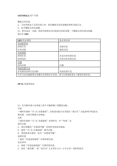
MOTOROLA用户手册删除无用信道1、当对讲机处于无用信道上时,按住删除无用信道键直到听见提示音。
2、松开删除无用信道键。
注:要具备这一功能,您的代理商必须为您的对讲机设置一个删除无用信道功道键。
指示灯LEDGP 88s快速参阅法注:在空格内填入对讲面上两个可编程键上预置的功能。
开机·顺时针旋转“开/关/音量旋钮”,自检成功提示音及绿色“指示灯”亮起表明开机成功。
相反地,自检失败提示音响起。
关机·逆时针旋转“开/关/音量旋钮”直到听见一声“咔哒”音。
调节音量1、按住预置的“音量调节键”直到听见持续音响起。
2、旋转“开/关/音量旋钮”调节音量。
3、得到所需音量时,松开“音量调节键”。
选择信道·旋转“信道选择旋钮”以得所需信道。
发出呼叫1、旋转“信道选择旋钮”以得所需信道。
2、按住“通话键”,离“麦克风”2.5到5公分(1至2时)的距离说话。
3、说话完毕时松开“通话键”。
接收呼叫1、开机。
2、调节音量。
3、选择所需信道。
4、呼叫进来时,您将在所设置的音量上听到该呼叫。
摩托罗拉通讯产品有限质量担保与责任Ⅰ、本质量担保的范围与期限:摩托罗拉电子私人有限公司(MOTOTOLA ELECTRONICS PTE LTD)(以下称“摩托罗拉”)担保,凡下列摩托罗拉生产的“双向无线电对讲机产品”(以下称“产品”),自购买之日起,在正常使用与维修条件下,凡出现材料的制造缺陷,可享受如下期限的质量担保:“双向无线电对机”车载台和手机产品附件(包括电池、天线、充电器、皮带夹等)摩托罗拉根据自己的决定,将在质量担保期内,免费对“产品”进行修理(用新零件或修理好的零件)、更换(用新的“产品”或修饰理好的“产品”),或按“产品”的购买价格予以退款,条件是货时符合本质量担保之条款。
更换后的零件或电路板享受原适用质量担保期限。
所有的下的“产品”零件应归摩托罗拉所有。
本公开有限质量担保由摩托罗拉公提供给原始最终用户购买者,不得指定或转让给任何第三方。
SmartAX MT880d 快速入门(V100R001_01,路由,国内版)
项目 标准
规格 ADSL 标准
ADSL2 标准 ADSL2+标准
ITU G.992.1(G.dmt)Annex A ITU G.994.1(G.hs) ANSI T1.413 Issue 2 ITU G.992.3(G.dmt.bis)Annex A ITU G.992.5 Annex A
如果您的计算机使用的操作系统是 Windows XP,您可以使用 Windows XP 自带 的 PPP 拨号程序。在 Windows XP 操作系统中创建拨号连接的操作步骤如下:
1. 单击“开始 > 所有程序 > 附件 > 通讯 > 网络连接”菜单项。 2. 在“网络任务”栏,单击“创建一个新的连接”,弹出“新建连接向
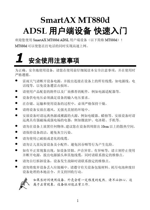
话线等,以免设备遭雷击损坏。 z 请使用产品配套的附件以及厂商推荐的配件,例如电源适配器等。 z 设备供电电压必须满足设备的输入电压要求。 z 在存储、运输和使用设备的过程中,必须严格保持干燥。 z 请将设备安放在通风、无强光直射的环境中。 z 安放设备时请远离热源或裸露的火源,例如电暖器、蜡烛等。安放设备时请
指示灯 POWER
状态 常亮 不亮
含义 MT880d 通电。 MT880d 未通电。
4
指示灯 ADSL LAN
DATA
状态 闪烁 常亮 不亮 闪烁 常亮 不亮 闪烁 不亮
含义 MT880d 正在激活。 MT880d 已激活。 MT880d 未接通电源。 以太网接口有数据流量。 以太网接口已经建立连接。
步骤 3 检查终端“LAN”指示灯是否点亮。
如果“LAN”指示灯不亮,请参考下面的说明进行检查。
1. 请检查计算机网卡是否已经启用。 2. 请检查终端和计算机之间的网线连接是否牢靠。请尝试重新插拔
GIGABYTE GA-M68MT-D3 GA-M68MT-S2P AM3 主板 说明书

业的技术人员。
硬件安装
-6-
1-2 产品规格
中央处理器(CPU) Hyper Transport Bus
支持AM3 插槽处理器: AMD Phenom™ II 处理器/ AMD Athlon™ II 处理器 (请至技嘉网站查询有关支持的处理器列表)
第三章 驱动程序安装 ............................................................................................35 芯片组驱动程序 ..................................................................................................... 35
1-1 安装前的注意事项......................................................................................... 6 1-2 产品规格 .......................................................................................................... 7 1-3 安装中央处理器及散热风扇 ....................................................................... 9
MT温控仪使用说明书
XMT7000系列温度控制仪说明书余姚市腾辉温控仪表厂2008 年2 月一、概述XMT7000系列智能温度控制器是一种经济型的智能工业调节仪表,广泛应用于机械、化工、陶瓷、轻工、冶金、石化、热处理等行业的温度、流量、压力、液位等的自动控制系统。
主要特点热电偶、热电阻、模拟量、频率脉冲等多种信号自由输入,量程自由设置软件调零调满度,冷端单独测温,放大器自稳零,显示精度优于%FS模糊理论结合传统PID方法,控制快速平稳,先进的自整定方案输出可选:继电器触点、逻辑电平、可控硅单相或三相过零和移相触发脉冲、模拟量,另附二路可定义的报警触点输出二、主要技术指标1.输入逻辑电平:DC 0/12V热电偶K E S J T B R N 过零触发脉冲:光偶可控硅输出 1A 600V热电阻 Pt100 JPt100 Cu50 移相触发脉冲:光偶可控硅输出1A 600V线性信号 0-5V 1-5V mV Ω0-10mA电流输出(负荷阻值600Ω以下)0-10mA 0-20mA 4-20mA 0-20mA电流输出(负荷阻值600Ω以下)4-20mA电流输出(负荷阻值600Ω以下)8.控制方式:模糊PID控制、位式控制2.基本误差:输入满量程的±%±1个字9.电源电压: AC85-264V(50/60Hz)3.分辨率: 1℃、(额定100-240V AC)4.采样周期:2次/sec AC(额定24V AC)5.报警功能:上限,下限,上偏差,下偏差, DC (额定 24V DC)区间外,区间内10.工作环境:温度0-50℃,湿度<85%RH 的6.报警输出:继电器触点 AC250V 3A(阻值)无腐蚀性场合,功耗<5VA7.控制输出:继电器触点 AC250V 3A(阻值)11.面板尺寸:80×160,160×80,96×96,72×72,48×96,96×48,48×48mm三、产品确认请参照下列代码确认送达产品是否与您指定的型号一致。
MT9600-UFI使用说明书

MT9600-UFI使用说明书一、外观与功能介绍序号名称功能与说明1标准USB口连接PC与数据卡2SIM卡槽使用标准SIM卡3TF卡槽支持32GB的T-flash卡4信号指示灯红灯搜网或者无信号,绿灯有信号而且非常好;信号灯闪烁正在注册网络,信号灯常亮已经注册到网络二、使用说明2.1SIM卡的安装使用标准的SIM大卡,卡芯朝下,缺口向外插入SIM卡卡槽中,(插拔SIM卡时请在设备断电状态下操作,否则可能损坏您的SIM卡或者造成设备的故障,影响正常使用该设备)2.2WiFi的连接用手机或笔记本电脑搜索WiFi:4G-UFI-XXXX,输入密码:1234567890点确定连接设备的WiFi2.3网关登陆在浏览器地址栏输入192.168.100.1点确定进入网关登陆页面如上图,在界面右上角可以选择语言(支持中文/英文)默认用户名、密码:admin点登陆进入管理界面。
2.4网关管理可以查看设备信息、修改个性设置(流量查看与管理,APN管理,WiFi名称、密码的修改,短息管理等)2.5网络——APN配置一些特殊的SIM卡需要添加APN信息之后才可以正常使用2.6网络——流量统计在这里可以查看流量使用记录,(运营商的流量计算方式可能与设备的流量计算方式不同,以运营商的流量使用为准)2.7流量——流量管理流量管理默认为关闭,可以根据个人情况开启使用流量控制。
2.8WLAN——WLAN管理修改设备的WiFi名称(SSID)、密码,同时连接设备的人数。
开启WPS 功能,可以免输WiFi密码连接设备WiFi。
2.9系统管理修改登录网关的用户名、密码,查看设备信息(IMEI、软件版本、WLAN MAC地址),设备操作(恢复出厂设置、重启设备、关机),时间管理,通讯录(可以添加、删除联系人)2.10短信管理可以接收、发送短信息2.11本设备除了可以给带有WiFi功能的手机、笔记本电脑、平板等提供WiFi上网外,还可以给没有无线网络的一台台式电脑提供上网。
mts用户手册
目录MTS使用环境与安装说明 (8)一、概述 (9)1.1 MTS软件介绍 (9)1.2 操作界面说明 (11)1.3 约定 (14)二.通用功能 (17)2.1工程文件操作 (17)2.1.1新建 (17)2.1.2打开和关闭 (19)2.1.3保存和另保存 (19)2.1.4输出屏幕DXF、输出三维DXF和输出屏幕BMP (20)2.1.5升级工程 (20)2.1.6打印、打印预览及打印设置 (20)2.2工程设定 (22)2.2.1楼面表 (22)2.2.2轴线表 (23)2.2.3构件组及优化与调整功能 (24)2.2.4设置当前单位 (26)2.2.5设置当前参数 (27)2.3视图功能 (29)2.3.1整体视图、选中视图、轴线视图及楼面视图 (29)2.3.2轴线网格 (29)2.3.3显示网格点 (30)2.3.4显示轴线编号和显示轴线间距 (30)2.3.5前图和后图功能 (30)2.3.6平面视图变换 (30)2.3.7三维视图变换 (31)2.3.8通用工具栏及建模、楼面、轴线和视图工具条 (31)2.3.9开关功能 (32)2.3.10标注方式 (33)2.3.11杆件、墙体自动打断 (35)2.3.12中点、垂足捕捉功能 (35)2.3.13显示功能 (36)2.3.14显示荷载 (36)2.3.15楼层快速切换功能 (36)2.4选择功能 (38)2.4.1选择结点 (38)2.4.2选择杆件和选择次梁 (38)2.4.3选择房间 (39)2.4.4选择墙体 (39)2.4.5选择构件 (40)2.4.6选择平面 (40)2.4.7选择轴线 (41)2.4.8属性选择 (41)2.4.9杆件过滤 (41)2.4.10编号选择 (41)2.5查询功能 (43)2.5.1工程查询 (43)2.5.2结点查询 (44)2.5.3杆件查询 (46)2.5.4房间查询 (50)2.5.5墙体查询 (51)2.5.6双击杆件查询 (51)2.6工具 (52)2.6.1测量两点距离 (52)2.6.2测量房间面积 (52)2.6.3测量楼面面积 (52)2.6.4测量建筑面积 (52)2.6.5测量结构重量 (53)2.6.6结点、杆件、墙梁、墙肢的编号重排 (53)三.建模功能 (54)3.1轴线功能 (54)3.1.1轴线表 (54)3.1.2 定义直轴线 (55)3.1.3 定义弧轴线 (56)3.1.4 定义多义轴线 (56)3.1.5 编辑轴线属性 (57)3.1.6轴线删除 (57)3.1.7 平行复制轴线 (58)3.1.8 旋转复制轴线 (58)3.1.9 镜向复制轴线 (59)3.1.10 规则轴线快速输入 (59)3.2网格功能 (60)3.3建模功能 (62)3.3.1定义孤立节点 (62)3.3.2删除孤立节点 (62)3.3.3结点坐标调整 (62)3.3.4去除多余节点 (63)3.3.5梁柱输入 (63)3.3.6支撑输入 (64)3.3.7平面布柱 (65)3.3.8 杆件拆分 (65)3.3.9 杆件合并 (66)3.3.10杆件打断 (67)3.3.11定义墙体 (67)3.3.12钢板剪力墙定义 (68)3.3.13洞口定义 (68)3.3.14修改洞口 (69)3.3.15洞口复制 (69)3.3.16修改墙厚 (70)3.3.17墙体打断 (70)3.3.18墙体拆分 (70)3.3.19墙体合并 (71)3.3.20轴向复制 (71)3.3.21弧向复制 (72)3.3.22镜向复制 (74)3.3.23空间平移 (75)3.3.24空间复制 (75)3.3.25楼层快速复制 (76)3.3.26框架快速输入 (77)3.3.27支撑快捷输入 (78)3.3.28门式刚架快速生成 (79)3.3.29 屋架快速输入 (81)3.3.30快捷添加弧型构件 (84)3.3.31撤销和重做 (85)3.4材料库 (86)3.5工程截面库功能 (88)3.5.1布置截面功能及工程截面库概述 (88)3.5.2工程截面库使用说明 (93)3.6属性设计 (104)3.6.1结点类型设定 (104)3.6.2杆件类型设定 (104)3.6.3主次梁模式设定 (104)3.6.4变截面放置参数 (104)3.6.5杆件体型系数定义 (105)3.6.6构件对齐方式设定 (105)3.6.7檐口设定 (106)3.6.8女儿墙设定 (106)3.6.9梁位置类型设定、梁位置自动设定 (106)3.6.10定义支座 (107)3.6.11定义方位 (108)3.6.12定义释放、定义刚臂和定义偏心 (109)3.7楼面操作工具 (112)3.7.1次梁布置 (112)3.7.2次梁复制 (114)3.7.3次梁删除 (114)3.7.4定义导荷模式 (114)3.7.5房间楼板厚度 (116)3.7.6房间全开洞 (117)3.7.7房间局部开洞 (117)3.7.8房间洞口复制 (118)3.7.9房间洞口取消 (118)3.7.10局刚定义(房间方式) (118)3.7.11局刚定义(结点方式) (119)3.7.12取消已定义局刚 (119)3.8荷载布置 (120)3.8.1恒载和活载布置 (120)3.8.2风载布置 (122)3.8.3地震作用定义 (127)3.8.4吊车荷载作用定义 (128)3.8.5温度荷载作用定义 (131)四.计算分析功能 (132)4.1模型检查 (132)4.2结构计算 (133)4.3读入结果文件 (134)4.4弹性时程分析 (135)4.5二阶弹性分析 (138)4.6罕遇地震验算 (139)五.后处理功能 (140)5.1公共功能 (140)5.1.1自振特性回显 (140)5.1.2内力位移回显 (141)5.1.3荷载组合 (142)5.1.4杆件类型设定 (145)5.1.5杆件计算长度设定 (146)5.1.6抗火验算 (146)5.2多高层后处理功能 (148)5.2.1柱位置类型设定 (148)5.2.2主次梁模式设定 (148)5.2.3组合梁栓钉设定 (148)5.2.4主梁内力调整设定 (149)5.2.5次梁规范验算 (150)5.2.6杆件规范验算 (150)5.2.7构件配筋设计 (153)5.2.8组合梁栓钉删除 (153)5.2.9组合梁栓钉设计 (154)5.2.10组合梁施工阶段验算 (154)5.2.11简支组合梁独立设计 (155)5.2.12工程楼板库 (155)5.2.13楼板快速复制 (157)5.2.14楼板设计 (159)5.2.15楼板验算 (160)5.2.16计算书输出 (160)5.2.17自振特性报告 (162)5.2.18层抗侧刚度比报告 (163)5.2.19层受剪承载力报告 (163)5.2.20楼层地震剪压比报告 (164)5.2.21最大层间位移报告 (164)5.2.22质心层间位移报告 (165)5.2.23多塔质心层间位移报告 (166)5.2.24墙体配筋报告 (166)5.2.25等效荷载报告 (167)5.2.26总体概算报告 (167)5.2.27详细概算报告 (168)5.3厂房后处理功能 (169)5.3.1缀板缀条布置功能 (169)5.3.2杆件规范验算 (170)5.3.3变形验算 (173)5.3.4吊车梁设计 (173)5.3.5轻钢檩条设计 (176)5.3.6轻钢墙梁设计 (178)5.3.7抗风柱设计 (181)5.3.8屋面支撑设计 (182)5.3.9柱间支撑设计 (185)5.3.10工程计算书输出 (187)5.3.11自振特性报告 (188)5.3.12总体概算报告 (188)六节点设计模块 (189)6.1节点自动识别 (189)6.2节点模块开关 (189)6.3选择设计的节点形式 (189)6.4选择节点的连接形式 (190)6.5设计和自动设计功能 (191)6.6新建连接组、编辑、删除和选中节点组 (191)6.7 预览功能 (191)6.8 计算书输出 (191)6.9节点组定义 (192)6.10重置 (192)6.11刷新杆端力 (192)6.12节点设计方法 (192)6.13抗震设计 (193)七.基础设计模块 (194)7.1桩布置 (194)7.1.1桩基定义 (194)7.1.2桩基布置 (194)7.1.3桩基复制 (194)7.2桩群承载力计算 (195)7.3桩群中心调整 (195)7.4底层信息查询 (196)7.4.1底层信息查询 (196)7.4.2合力查询 (196)7.4.3桩信息查询 (197)7.4.4独立基础查询 (197)7.4.5基础梁查询 (197)7.5独立基础设计 (198)7.5.1基础组添加 (198)7.5.2基础尺寸确定、基础配筋设计 (199)7.6基础梁设计 (201)7.6.1基础梁定义 (201)7.6.2基础梁设计 (201)7.7条形基础设计 (202)7.7.1条形基础定义 (202)7.7.2条形基础设计 (202)7.8出图 (205)八.自动出图模块 (206)8.1多高层结构布置图 (206)8.2楼板图 (210)8.3多高层剪力墙布置图 (211)8.4节点图 (212)8.5基础图 (213)8.6结果简图 (214)8.7厂房布置图 (215)8.8构件图 (220)附录1:分析准备文件—C AL目录下C OMMON.DAT (221)附录2:自定义地震波数据文件 (225)附录3:MTS程序文件 (226)附录4:MTS程序的配筋文本及简图格式 (227)1.配筋信息文本文件 (227)2.各层配筋简图 (227)附录5:空间结构输出计算书格式 (229)MTS使用环境与安装说明MTS使用环境:●操作系统:中文Windows 98/Me/2000Pro/2000Srv/XP(注:如果使用其它语言的Windows版本,请外挂中文平台);●机型至少为P166,建议使用PII266以上机型;●内存至少32M,建议使用64M或128M内存;●至少100兆以上的硬盘空间;●建议安装软件:Microsoft Office、AutoCAD。
ToolsTalk MT 安装和升级手册说明书
ToolsTalk MT Printed Matter No.9839 0544 00Publication Date 2018-07-30Installation and Upgrade ManualTable of ContentsEN Installation and Upgrade Manual (3)FR Manuel d'installation et de mise à niveau (8)DE Installations- und Upgrade-Anleitung (13)ES Manual de instalación y actualización (18)ZH安装和升级手册 (23)2© Atlas Copco Industrial Technique AB - 9839 0544 00ToolsTalk MT EN General Data Protection Regulation (GDPR) This product offers the possibility to process personal identifiable information such as system user name,role and IP-address. The purpose of this processing capability could be to enhance quality control throughtraceability and proper access management.If you decide to process personal data you need to be aware of and comply with relevant personal dataprotection rules, including, in the EU the GDPR as well as other applicable laws, directives and regula-tions. Atlas Copco can in no way be held liable for any use made by you of the product.© Atlas Copco Industrial Technique AB - 9839 0544 003Liability EN ToolsTalk MT Many events in the operating environment may affect the tightening process and shall require a validationof results. In compliance with applicable standards and/or regulations, we hereby require you to check theinstalled torque and rotational direction after any event that can influence the tightening result. Examplesof such events include but are not limited to:■initial installation of the tooling system■change of part batch, bolt, screw batch, tool, software, configuration or environment■change of air- or electrical connections■change in line ergonomics, process, quality procedures or practices■changing of operator■any other change that influences the result of the tightening processThe check should:■Ensure that the joint conditions have not changed due to events of influence.■Be done after initial installation, maintenance or repair of the equipment.■Occur at least once per shift or at another suitable frequency.4© Atlas Copco Industrial Technique AB - 9839 0544 00ToolsTalk MT EN IntroductionAbout the documentThis document provides user instructions for Atlas Copco Tools AB . The purpose of the document is toprovide, adequate information regarding daily use, independent of reader competence.See also2Conventions [5]ConventionsTo enhance user understanding, certain formatting conventions are used throughout this document. Theformatting conventions used are listed in the table below.Manual conventions© Atlas Copco Industrial Technique AB - 9839 0544 005Installation restrictions EN ToolsTalk MT Installation restrictions6© Atlas Copco Industrial Technique AB - 9839 0544 00ToolsTalk MT EN Software installationInstalling ToolsTalk MT and MTComTo install ToolsTalk MT and MTCom, perfrom the following steps:1.Open a web browser.2.Enter /ttmt .This will initialize the download of the .exe file.3.Accept the download.4.Run the .exe to start the installation wizard.5.Follow the installation steps.6.Click Finish to close the installation wizard.ToolsTalk MT and MTCom are now installed on the computer.© Atlas Copco Industrial Technique AB - 9839 0544 007Règlement général sur la protection des données(GDPR)FR ToolsTalk MT Ce produit offre la possibilité de traiter des informations personnellement identifiables telles que le nomd'utilisateur du système, le rôle et l'adresse IP. Le but de cette capacité de traitement est d'améliorer lecontrôle de la qualité grâce à la traçabilité et à la bonne gestion des accès.Si vous décidez de traiter des données personnelles vous devez connaître et respecter les règles de pro-tection des données personnelles correspondantes, y compris le GDPR dans l'UE ainsi que les autreslois, directives et réglementations applicables. Atlas Copco ne peut en aucun cas être tenu responsablede quelconque utilisation faite par vous du produit.8© Atlas Copco Industrial Technique AB - 9839 0544 00ToolsTalk MT FR ResponsabilitéDe nombreux évènements dans l'environnement d'exploitation peuvent affecter le processus de serrageet nécessiteront une validation des résultats. Conformément aux normes et règlements applicables, nousvous invitons par la présente à contrôler le couple installé et le sens de rotation après tout évènementsusceptible d'avoir une incidence sur le résultat du serrage. Voici des exemples non exhaustifs de cesévènements :■installation initiale du système d'outillage■modification de lot de pièces, boulon, lot de vis, outil, logiciel, configuration ou environnement■modification des branchements pneumatiques ou électriques■changement dans l'ergonomie de la ligne, le processus, les procédures de qualité ou les pratiques■changement d'opérateur■tout autre changement ayant une incidence sur le résultat du processus de serrageLe contrôle devra :■Garantir que les conditions d'assemblage n'ont pas changé en raison d'évènements susceptibles d'avoir une incidence sur le processus.■Être effectué après l'installation initiale, la maintenance ou la réparation du matériel.■Intervenir au moins une fois par prise de poste ou à toute autre fréquence adéquate.© Atlas Copco Industrial Technique AB - 9839 0544 009Introduction FR ToolsTalk MTÀ propos du documentCe document fournit les instructions d'utilisation du produit suivant d'Atlas Copco Tools AB . Il a pour ob-jet de fournir des renseignements adéquats concernant l'utilisation au quotidien de , indépendamment descompétences du lecteur.Voir également2Conventions [10]ConventionsDans un souci de compréhension pour l'utilisateur, certaines conventions de formatage sont utilisées dansce document. Les conventions de formatage utilisées sont listées dans le tableau ci-dessous.Conventions du manuel10© Atlas Copco Industrial Technique AB - 9839 0544 00ToolsTalk MT FR Restrictions d'installation Restrictions d'installationInstallation logicielle FR ToolsTalk MTInstallation de ToolsTalk MT et MTComPour installer ToolsTalk MT et MTCom, procédez de la manière suivante :1.Ouvrez un navigateur web.2.Tapez /ttmt .Ceci initialise le téléchargement du fichier .exe.3.Acceptez le téléchargement.4.Exécutez le fichier .exe pour démarrer l’assistant d’installation.5.Suivez les étapes d’installation.6.Cliquer sur Finish pour quitter l'assistant d’installation.ToolsTalk MT et MTCom sont maintenant installés sur l’ordinateur.ToolsTalk MT DE Allgemeine Datenschutzverordnung (GDPR) Dieses Produkt bietet die Möglichkeit, personenbezogene Informationen wie den Systembenutzernamen,die Rolle und die IP-Adresse zu verarbeiten. Der Zweck dieser Verarbeitungsfähigkeit könnte darin beste-hen, die Qualitätskontrolle durch Rückverfolgbarkeit und geeignetes Zugriffsmanagement zu verbessern.Wenn Sie sich dazu entschließen, personenbezogene Daten zu verarbeiten, müssen Sie die einschlägi-gen Datenschutzbestimmungen kennen und einhalten, einschließlich der DSGVO sowie anderer in derEU anwendbarer Gesetze, Richtlinien und Vorschriften. Atlas Copo kann in keiner Weise für die Verwen-dung des Produkts durch Sie haftbar gemacht werden.Haftung DE ToolsTalk MT Viele Ereignisse in der Arbeitsumgebung können sich auf die Verschraubung auswirken und bedürfen ei-ner Validierung der Ergebnisse. In Übereinstimmung mit den geltenden Standards und/oder Vorschriftensind das installierte Drehmoment und die Drehrichtung nach einem Ereignis zu überprüfen, das sich aufdie Verschraubung auswirken kann. Zu solchen Ereignissen zählen unter anderem:■Erstinstallation des Werkzeugsystems■Änderung von Chargen, Bolzen, Schrauben, Werkzeugen, Software, Konfiguration oder Umgebung■Änderung von Druckluft- oder Elektroanschlüssen■Änderung von Linienergonomie, Prozessen, Qualitätsverfahren und -praktiken■Bedienerwechsel■Andere Änderungen, die sich auf das Ergebnis der Verschraubung auswirkenDie Prüfung muss:■Sicherstellen, dass die gemeinsamen Bedingungen sich nicht aufgrund von Ereignissen geändert ha-ben.■Nach der Erstinstallation, Wartung oder Reparatur der Anlage erfolgen.■Mindestens einmal pro Schicht oder in einem anderen geeigneten Intervall erfolgen.ToolsTalk MT DE EinleitungZum DokumentDieses Dokument enthält Bedienungsanleitungen für Atlas Copco Tools AB . Dieses Dokument soll aus-reichende Informationen über den täglichen Gebrauch des unabhängig von der Kompetenz des Lesersliefern.Vgl. auch:2Konventionen [15]KonventionenZur Verbesserung des Benutzerverständnisses werden in diesem Dokument bestimmte Formatierungenverwendet. Die verwendeten Formatierungen sind in der unteren Tabelle aufgeführt.HandbuchkonventionenInstallationseinschränkungen DE ToolsTalk MT InstallationsbeschränkungenToolsTalk MT DE SoftwareinstallationInstallation von ToolsTalk MT und MTComFühren Sie die folgenden Schritte aus, um ToolsTalk MT und MTCom zu installieren:1.Öffnen Sie einen Webbrowser.2.Rufen Sie die Adresse /ttmt auf.Dadurch wird der Download einer EXE-Datei initialisiert.3.Akzeptieren Sie den Download.4.Führen Sie die EXE-Datei aus, um den Installationsassistenten zu starten.5.Folgen Sie den Schritten des Installationsassistenten.6.Klicken Sie auf Beenden, um den Installationsassistenten zu verlassen.ToolsTalk MT und MTCom sind jetzt auf dem Computer installiert.Reglamento general en materia de protección dedatos (GDPR)ES ToolsTalk MT Este producto ofrece la posibilidad de procesar información personal identificatoria como el nombre deusuario del sistema, su función y su dirección IP. El propósito de esa función de procesamiento podría sermejorar el control de calidad a través de la trazabilidad y de una adecuada gestión de los accesos.Si decide procesar datos personales, deberá conocer y cumplir las normas sobre protección de datos per-sonales aplicables, incluyendo el GDPR en la UE así como cualesquiera otras leyes, directivas y regla-mentos que sean de aplicación. Atlas Copco no será en ningún caso responsable del uso que usted reali-ce del producto.ToolsTalk MT ES Responsabilidad Muchas circunstancias del entorno de trabajo pueden afectar al proceso de apriete y requerir la validaciónde los resultados. En cumplimiento de las normas y/o reglamentación aplicables, le solicitamos que com-pruebe el par instalado y la dirección de giro después de cualquier circunstancia que pueda afectar al re-sultado del apriete. Ejemplos de este tipo de circunstancias son, aunque sin limitarse a ellos:■Instalación inicial del sistema de mecanizado■Cambio del lote de piezas, perno, lote de tornillo, herramienta, software, configuración o entorno■Cambio de conexiones neumáticas o eléctricas■Cambio en la ergonomía, procesos, procedimientos o prácticas de control de calidad■cambio de operador■Cualquier otro cambio que influya en el resultado del proceso de aprieteLa comprobación debería:■Asegurar que las condiciones de la junta no hayan cambiado debido a las circunstancias influyentes.■Realizarse después de la instalación inicial, un mantenimiento o la reparación del equipo■Realizarse al menos una vez por cada turno o con otra frecuencia adecuadaIntroducción ES ToolsTalk MTAcerca de este documentoEste documento contiene instrucciones de usuario para las herramientas Atlas Copco AB . El objetivo deeste documento es proporcionar información adecuada sobre el uso diario de , al margen de los conoci-mientos del lector.Consulte también2Convenciones [20]ConvencionesPara ampliar la comprensión del usuario, se utilizan ciertas convenciones a lo largo de este documento.Las convenciones de formato se listan en la tabla a continuación.Convenciones manualesToolsTalk MT ES Restricciones de instalación Restricciones de instalación© Atlas Copco Industrial Technique AB - 9839 0544 0021Instalación del software ES ToolsTalk MTInstalación de ToolsTalk MT y MTComPara instalar ToolsTalk MT y MTCom, siga estos pasos:1.Abra un navegador web.2.Escriba /ttmt .Esto iniciará la descarga del archivo .exe.3.Acepte la descarga.4.Ejecute el archivo .exe para iniciar el asistente de instalación.5.Siga los pasos de instalación.6.Haga clic en Finalizar para cerrar el asistente de instalación.ToolsTalk MT y MTCom están ya instalados en su ordenador.22© Atlas Copco Industrial Technique AB - 9839 0544 00ToolsTalk MT ZH一般数据保护条例(GDPR)本产品提供了处理个人身份信息的可能性,例如系统用户名、角色和 IP 地址。
AC8688 ZH-S 用户手册说明书
AC8688ZH-S用户手册3EN User manual251 重要事项安全使用本产品之前,请仔细阅读本用户手册,并妥善保管以备日后参考。
危险• 切勿让水或任何其它液体或易燃性清洁剂进入产品,以免发生触电和/或火灾。
• 切勿用水或任何其它液体或(易燃性)清洁剂来清洁产品,以免发生触电和/或火灾。
• 切勿在产品周围喷洒杀虫剂或香水等任何可燃材料。
警告• 在将产品连接电源之前,请先检查产品所标电压与当地的供电电压是否相符。
• 如果电源软线损坏,为避免危险,必须由制造厂或其维修部或类似的专职人员来更换。
• 如果插头、电源线或产品本身受损,请勿再使用本产品。
• 本产品适合由 8 岁或以上年龄的儿童以及肢体不健全、感觉或精神上有障碍或缺乏相关经验和知识的人士使用,但前提是有人对他们使用本产品进行监督或指导,以确保他们安全使用,并且让他们明白相关的危害。
不得让儿童玩耍本产品。
请勿让儿童在无人监督的情况下清洁和保养产品。
• 请勿堵塞进风和出风口,例如不要将物体放置在出风口上或进风口前方。
• 确保异物未通过出风口进入产品内部。
小心• 本产品不能替代正常通风、日常吸尘或者在烹饪时使用的抽油烟机。
• 如果连接产品的电源插座接触不良,则产品的插头可能会变得很热。
确保所连接的电源插座接触良好。
• 一定要在干燥、稳固、平整且水平的表面上放置和使用本产品。
• 产品的后侧及两侧均要留出至少 20 厘米的空间,产品上方至少要留出 30 厘米的空间。
• 切勿在本产品上放置任何物品。
• 请勿坐在或站在产品上面。
坐在或站在产品上面可能导致潜在的人身伤害。
• 切勿将产品直接放在空调下方,以防冷凝水滴到产品中。
4ZH-S简体中文5ZH-S •打开产品电源之前,务必确保已经正确安装所有过 滤网。
•只能使用飞利浦专门为本产品设计的原装过滤网。
切勿使用任何其它过滤网。
• 燃烧滤网可能会造成不可逆转的人体危害和/或危及其他生命。
请勿将滤网用作燃料或类似用途。
MT11远程表产品说明书
MT Series——Remote MeterUser ManualModels:MT11Contents1.Important Safety Instructions (1)2.Overview (2)3.Product classification (3)4. Installation (4)4.1 Base of MT11 (Optional accessory) (4)4.2 Wall installation steps (5)4.3 Surface mounting steps (7)5.Product Features (8)5.1 Front View (8)5.2 Rear View (9)6.Display and operation (11)6.1LCD display (11)6.2 Auto global view mode (12)6.3 Temperature units (14)6.4 Clear the generated energy (14)6.5 Battery type (15)6.6 Fault indication (19)7.Technical Specifications (20)Thank you for selecting the remote meter.General safety information•Please contact our company or transportation if the product has been damaged.•Please read this manual carefully before using the product and pay attention to the safety information.•Keep the product away fromrain, exposure, severedust, vibrations,corrosive gas and intense electromagnetic interference. •Do not allow water to enter the product.•There are nouse rserviceable parts inside the product. Do not disassemble or attempt to repairit.Recommendations•The MT11 is only allowed to connect with DR N series charge controller.Please confirm before purchase and installation.• Please do not install MT11 in a situation with strong electromagnetic interference.The MT series remote meter is an accessory which is compatible with the DuoRacer series controller. It can monitor the running data and working status of the controller via the remote meter. The remote meter can browse the controller’s parameters, set the battery typeand temperature unit, and clean the generated energy.It is suitable for RV, Camper, Boat, and so on.Features:•Automatically identify and display the type,model and relevant parameter data of controllers.•Real-time display the operational data and working status of the connected devices indigital,graphics and textual forms by a large-screen multifunction LCD.•Three touch buttons are easy and quick to operate.•No need for external power supply. Charge controller supply the power for MT11.•It can browse the controller’s parameters, set the battery typeand temperature unit, and clean the generated energy.•Real-time display of failure information of the connected devices. •Longer communication distance based on RS485.1) MT11(include the 1.5m communication cable)✦ Remote meter MT11✦ 1.5m communication cable(Model: CC-RS485-RS485-3.81-4P-150)✦Base of MT112) MT11 (include the 5m communication cable)✦Remote meter MT11✦5m communication cable(Model: CC-RS485-RS485-3.81-4P-500)✦Base of MT113) MT11 (include the 10m communication cable)✦Remote meter MT11✦10m communication cable(Model:CC-RS485-RS485-3.81-4P-1000)✦Base of MT114) MT11(Do not include the communication cable)✦Remote meter MT11✦ 1.5m communication cable(Model: CC-RS485-RS485-3.81-4P-150)✦Do not include Base of MT11NOTE: The user can purchase the product according to the requirement.4.1 Base of MT11 (Optional accessory)4.2 Wall installation stepsStep1:Locate and drill screw holes based on the Frame Mounting dimension of the base,and erect the plastic expansion bolts.Step2:Use four PA4.2×32 self-tapping screws to fix the Frame.Step3:Remove the decorative shell.Step4:Use four M4×8 pan head screws to mount MT11 Surface on the Frame. Step5:Install the decorative shell.4.3 Surface mounting stepsStep1: Locate and drill screw holes based on the installation size of the surface.Step2: Remove the decorative shellStep3:Use four M4×8 cross recessed pan head screws with M4 nuts to mount MT11 surface onto the panel.Step4:Install the decorative shellNOTE:Take full consideration of the plugging/unplugging space of the communication cable and the length of the cable during installation to see if they are appropriate.5.1 Front ViewLCD display screenMan-machine interaction operation interface. Refer to the chapter 5 display and operationButtonsThe meter buttons include two function buttons and one switch button.Press the button1.PV array parameters2.Storage battery parameters3.Browse the start battery parameters automatically ()Browse the PV array parameters5.2 Rear View✦RS485communicationportIt is used to connect the controller which Power the MT11. ✦Communicationcable’s modelsCC-RS485-RS485-3.81-4P-150(Included)CC-RS485-RS485-3.81-4P-1000(Optional)CC-RS485-RS485-3.81-4P-2000(Optional)✦Pins definition6.1LCD displayIconIconBATT1 battery capacityBATT1battery capacity BATT1battery capacity BATT1battery capacity BATT1battery capacityDisplay the parametersDisplay the parametersDisplay the parameters①Battery power calculated by the linear relationship disconnect voltage of low voltage and float charging voltage.6.2 Auto global view modeOperation:Step1: Press the button, is appear.Step2:Press the button, select the .Echo Loop:PV voltage ——PV current ——PV power——Battery power——BATT1 voltage——BATT1 current——Max. BATT1 voltage——Min.BATT1 voltage——BATT1 temperature——BATT1 battery type——BATT2 voltage——BATT2 current——Max. BATT1 voltage——Min.BATT2 voltage——PV voltage6.3 Temperature unitsOperation:Step1: Press the button under the battery temperature interface. Step2: Press the button to select the temperature unit.Step3: Press the button to set successfully.6.4 Clear the generated energyPress the andbutton and hold on 5s to clear the generated energy.6.5 Battery type1)Operation:Step1: Press the button and hold 5s under the battery type interface. Step2: Press the button when the battery type interface is flashing. Step3: Press the button to confirm the battery type.2) Battery typeBATT112V Sealed BATT124V SealedBATT112V Gel BATT124V GelBATT112V Flooded BATT124V FloodedLiFePO LiFePOLi-NiCoMn (3S) Li-NiCoMn (6S)UserCAUTION:The battery voltage is set as default and not changeable when selecting the default battery type. Please change to “User” battery type before adjusting the battery voltage.CAUTION: Set the voltage of the “User” battery type via PC software only.1) Lead-acid Battery Control Voltage ParametersThe parameters are in the 12V system at 25 ºC. Please double the1) When the battery type is sealed, gel, flooded, the adjusting range of equalizing duration is 0 to180min, and boost duration is 10 to180min.2) The following rules must be observed when modifying the value of the parameter in user battery type(factory default value is the same as sealed type):A. Over Voltage Disconnect Voltage > Charging Limit Voltage ≥ EqualizeCharging Voltage ≥ Boost Charging Voltage ≥ Float Charging Voltage > Boost Reconnect Charging Voltage.B. Over Voltage Disconnect Voltage > Over Voltage Reconnect VoltageC. Low Voltage Reconnect Voltage > Low Voltage Disconnect Voltage ≥Discharging Limit Voltage.D. Under Voltage Warning Reconnect Voltage > Under Voltage WarningVoltage ≥ Discharging Limit Voltage.Boost Reconnect Charging voltage > Low Voltage Disconnect Voltage.2)Lithium Battery Control Voltage ParametersThe parameters are in the 12V system at 25 ºC; please double theThe following rules must be observed when modifying the parameter values in User for the lithium battery.A.Over Voltage Disconnect Voltage>Over charging protectionvoltage(Protection Circuit Modules(BMS))+0.2V※;B.Over Voltage Disconnect Voltage>Over Voltage Reconnect Voltage=Charging Limit Volt age ≥ Equalize Charging Voltage=Boost Charging Voltage ≥ Float Charging Voltage>Boost Reconnect Charging Voltage;C.Low Voltage Reconnect Voltage>Low Voltage Disconnect Voltage ≥ Discharging Limit Voltage;D.Under Voltage Warning Reconnect Voltage>Under Voltage Warning Voltage≥ Discharging Limit Voltage;E.Boost Reconnect Charging voltage> Low Voltage Reconnect Voltage;F.Low Voltage Disconnect Voltage ≥ Over-discharging protection voltage(BMS)+0.2V.WARNING:The voltage parameters of the lithium battery can be set, but you must refer to the voltage parameters of lithium battery BMS.WARNING: The required accuracy of BMS shall be at least 0.2V. If the deviation is higher than 0.2V, the manufacturer will assume no liability for any system malfunction caused by this.6.6 Fault indicationindicatorBattery levelshows full, batteryframe blink, faulticon blink.Battery levelshows empty,battery frame blink,fault icon blink.Battery levelshows currentcapacity, batteryframe blink, faulticon blink, thetemperature iconblink.flashing Battery level shows empty, battery frame blink.No alarm for limited voltage fault when using Lithium batteries.Any changes without prior notice! Version number:1.1BEIJING EPSOLAR TECHNOLOGY CO., LTD. Tel: +86-10-82894896 / 82894112Fax: +86-10-82894882E-mail:******************Website: 。
- 1、下载文档前请自行甄别文档内容的完整性,平台不提供额外的编辑、内容补充、找答案等附加服务。
- 2、"仅部分预览"的文档,不可在线预览部分如存在完整性等问题,可反馈申请退款(可完整预览的文档不适用该条件!)。
- 3、如文档侵犯您的权益,请联系客服反馈,我们会尽快为您处理(人工客服工作时间:9:00-18:30)。
___________________________________________
FL – EM7688 嵌 入 式 wifi 模组用户手册
尊敬的用户,感谢您使用飞龙科技 EM7688 WIFI 模块。为了 便于您正确使用本模块,使用产品前请仔细阅读本用户手册,并 请妥善保管。
无线速率 数据接口
最高 150MBps UART、IIS、IIC、 SPI、PWM、GPIO
工作电压 工作温度
2.97-3.63V 0°C — 55°C
储存温度
-20°C — 70°C
尺寸
42mm × 30mm
软件参数
无线网络类型
AP/STA
安全机制 加密类型
WEP/WPA-PSK/WPA2-PSK/AES WEP64/WEP128
淘宝店铺销售
51
SD_D7/GPIO18
I/O
SD data7
52
SD_D6/GPIO19
I/O
SD data6
53
SD_D5/GPIO20
I/O
SD data5
54
SD_D4/GPIO21
I/O
SD data4
55
GND
Power
电源地
56
SD_WP
I
SD 写保护
57
SD_CD
I
SD 检测
58
GND
I-PEX 连接器
淘宝店铺销售
1.2.5 开发套件
飞龙科技提供 FL-EM7688 评估开发套件,供客户快速熟悉产品和进行深 度应用开发。
飞龙 FL-EM7688 评估开发套件特点: 1、 板载 USB 转串口芯片,通过 USB 线与电脑连接,既可给系统供电,也能调
试打印信息。再也不用额外使用外接电源和 232 转 TTL 模块了。 2、 核心板模块引出 UAB2.0 接口,SD 卡,网口和全部 IO,方便用户调试与二次
开发。
1.3 典型应用电路
淘宝店铺销售
50
GND
Power
淘宝店铺销售
Wifi 状态指示 电源地
UART1 发送 UART1 接收
电源 电源 电源地 I2S 数据输入 I2S 数据输出 I2S 左右声道对齐 I2S 位时钟 I2S 时钟 I2S 数据线 SPI 片选 1 SPI 主入从出 SPI 主出从入 SPI 片选 0 SPI 时钟 GPIO 0 UART0 发送 UART0 接收 电源地 网口 RX+ 网口 RX网口 TX+ 网口 TXPWM/从 SPI PWM/从 SPI UART2/从 SPI UART2/从 SPI 电源地
PWM、SPI master/slave。 丰富的 GPIO。
淘宝店铺销售
1.1.2 模块基本参数
分类 无线参数
硬件参数
参数
FL-EM7688 模块技术参数 数值
无线标准 频率范围
天线选项
IEEE 802.11 b/g/n 2.4GHz — 2.4835GHz 内置:板载陶瓷天线
I-PEX 连接器
1.1.1 模块特点
超小体积,长宽仅 42mm × 30mm。 邮票孔接口,方便安装。 内置陶瓷天线和 I-PEX 接口。 3.3V 单电源供电。 有线+无线路由器方案 支持 802.11 b/g/n 协议,最高 150Mbps。 有线支持 1WAN 或 1LAN,10M/100M 自适应。 适中的 RF 功率消耗。 板载 64MB DDR2 内存,8MB FLash。 480Mbps 高速 USB 接口。 3 路 UART(推荐 UART0 专用于系统 Debug)。 SD-XC、eMMC、PCM、IIS 数字音频接口(192K/24bits)、IIC 通讯接口、
14
GND
15
JTRST_N/LINK4
信号类型 Power PCIE PCIE PCIE PCIE PCIE PCIE I/O Power I/O Power I/O I/O Power I/O
说明 电源地 通用 GPIO 通用 GPIO 通用 GPIO 通用 GPIO 通用 GPIO 通用 GPIO
当 客 户 使 用 外 置 天 线 接 口 , 根 据 IEEE 802.11 b/g/n 标 准 的 要 求 ,
FL-EM7688 需要和 2.4G 的天线连接。外置天线的参数要求如下表所示:
项目
参数
频率范围
2.4 ~ 2.5GHz
阻抗
50Ω
VSWR
2(Max)
回波损耗
-10DB(Max)
连接类型
淘宝店铺销售
FL-EM7688 管脚定义
FL-EM7688 管脚功能定义
管脚
网络名
1
GND
2
PCIE_TXN0
3
PCIE_TXP0
4
PCIE_RXP0
5
PCIE_RXN0
6
PCIE_CKN0
7
PCIE_CKP0
8
#PERST_N
9
GND
10
REF_CLK0
11
GND
12
WPS_RST_PBC
13
CPURST_N
电源地 时钟输出 电源地 WatchDog 复位 系统复位 电源地
16
JTCLK/LINK3
I/O
17
JTMS/LINK2
I/O
18
JTDI/LINK1
I/O
19
JTDO/LINK0
I/O
20
WLED_N
O
21
GND
Power
22
#UART1_TX
O
23
UART1_RX
I
24
DVDD3.3
Power
TAMB=25℃ TAMB=25℃
最小值 -45
2.97 0
典型值
最大值 125 260
单位 ℃ ℃
3.3 3.62 V
3.3 V
2
KV
2
KV
1.2.3 机械尺寸
FL-EM7688 物理尺寸(单位 mm)如下图:
淘宝店铺销售
1.2.4 天线
FL- EM7688 支持板载陶瓷天线和外置天线。当客户使用内置天线时,需 要注意如下事项: 天线远离金属。至少与周围较高元器件保持 10mm 间距。 天线部分不能被金属外壳遮挡,塑料外壳至少保持 10mm 间距。
1.产品概述
淘宝店铺销售
1.1 概述
FL-EM7688 是武汉飞龙科技推出的低成本、低功耗高性能嵌入式 wifi 模组。 是一体化的 802.11 b/g/n WIFI 解决方案。FL-EM7688 WIFI 模组可以适用于很 多场合,比如有线转无线,3G 转 WIFI,无线摄像头,硬 AP,路由器、无线音箱, 无线存储等等。
O
40
UART0_RX
I
41
GND
Power
42
RXIP0模拟Fra bibliotek43RXIN0
模拟
44
TXOP0
模拟
45
TXON0
模拟
46
TXOP1/PWM_CH0/SPIS_CS
I/O
47 TXON1/PWM_CH1/SPIS_CLK
I/O
48 RXIP1/UART_TXD2/SPIS_MISO
I/O
49 RXIN1/UART_RXD2/SPIS_MOSI I/O
Power
电源地
59
SD_D1
I/O
SD data1
60
SD_D0
I/O
SD data0
61
SD_CLK
O
SD 时钟
62
SD_CMD
I/O
SD 命令
63
SD_D3
I/O
SD data3
64
SD_D2
I/O
SD data2
65
GND
Power
电源地
66
USB_DP
I/O
USB2.0 D+
67
USB_DM
I/O
USB2.0 D-
68
GND
Power
电源地
69
GND
Power
电源地
注: 1、红色带“#”前缀信号用于启动系统配置,外部不可驱动,不要上下拉。
1.2.2 电气特性
参数 存放温度范围 最大焊接温度
工作电压 任意 I/O 电压 静电释放量(人体模型) 静电释放量(充电设备模型)
条件 IPC/JEDEC J-STD-020
25
DVDD3.3
Power
26
GND
Power
27
I2S_DI
28
#I2S_DO
29
I2S_WS
30
I2S_CLK
31
I2C_SCLK
32
I2C_SD
33
#SPI_CS1
34
SPI_MISO
I
35
#SPI_MOSI
O
36
SPI_CS0
O
37
#SPI_CLK
O
38
GPIO_0
I/O
39
#UART0_TX
定制开发
提供 SDK 供客户二次开发
1.1.3 主要应用领域
物联网应用 WIFI 智能家居 WIFI 安防监控 工业控制 消费类电子 有线转无线 硬 AP 3G 转 WIFI 路由器 无线摄像头 无线音箱 无线存储
1.2 硬件介绍
淘宝店铺销售
1.2.1 管脚定义