焊接模拟示例-1
simufact.welding焊接模拟教程.pdf
simufact.welding焊接模拟教程.pdfsimufact.welding焊接模拟教程案例文件,请使用simufact.welding3.1.0及以上版本打开之前一直都是发的forming的教程,而simufact.welding网上的资料相对较少,其实simufact.welding软件也是一款很不错的软件,以往我们做焊接非线性大多数都是用marc,但是marc那个不人性化的界面,以及建模的复杂,让新手们望而却步。
simufact基于marc 和ife.weldsim两个求解器,取长补短,开发了极易使用的模拟软件,今天我就带大家一起来体验一下吧。
欢迎捧场噢!1、打开simufact.welding3.1.0软件。
点击新建按钮创建一个新的仿真模拟。
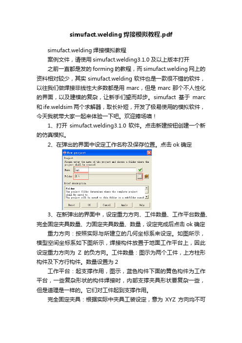
2、在弹出的界面中设定工作名称及保存位置。
点击ok确定3、在新弹出的界面中,设定重力方向、工件数量、工作平台数量、完全固定夹具数量、力固定夹具数量、数量,设定完成后点击ok确定重力方向:按照实际与所建立的几何坐标系来设定。
如图所示,模型空间坐标系如下图所示,焊接构件放置于地面工作平台上,因此设定重力方向为Z的负方向。
工件数量:图示为两个工件,上方柱形构件及下方行构件。
数量设置为2工作平台:起支撑作用,图示,蓝色构件下面的黄色构件为工作平台,一些复杂形状的构件焊接时,内部支撑夹具形状要复杂一些,但是道理是一样的。
它们对工件起到支撑作用。
完全固定夹具:根据实际中夹具工装设定,意为XYZ方向均不可动。
里固定:施加一定的力,使工件固定。
如图示蓝色板类件上面的四个小圆柱,通过它们施加一定的力,让压在工作平台上。
数量:中用到的机械手数量,有些工艺需要多个机械手同时进行焊接,按照实际定义即可。
本案例为一个机械手,顺序焊接底部四条直线焊缝,没道焊缝之间间隔一段时间(机械手转向)。
4、在软件catalog空白区域点击鼠标右键,在弹出的对话框中选择Geometries(几何)——Import(导入),然后在弹出的对话框中选择要导入的几何模型,可以一次性导入所有模型,在后面弹出的单位选择对话框中选择你建模时所用的单位,然后将use for all geometries前面勾选,意为所有几何模型的单元都采用当前单位。
焊接示意图详解,赶快抱走!
焊接⽰意图详解,赶快抱⾛!⼀、焊接接头的种类及接头型式焊接中,由于焊件的厚度、结构及使⽤条件的不同,其接头型式及坡⼝形式也不同。
焊接接头型式有:对接接头、T形接头、⾓接接头及搭接接头等。
(⼀)对接接头两件表⾯构成⼤于或等于135°,⼩于或等于180°夹⾓的接头,叫做对接接头。
在各种焊接结构中它是采⽤最多的⼀种接头型式。
钢板厚度在6mm以下,除重要结构外,⼀般不开坡⼝。
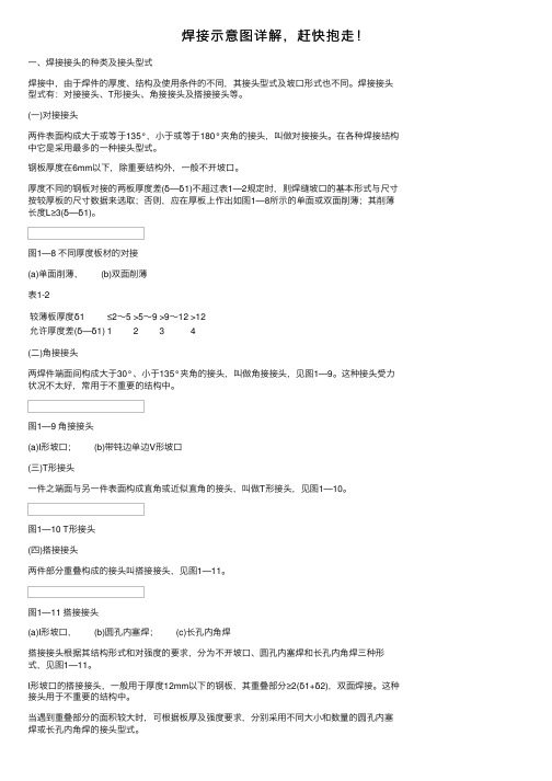
厚度不同的钢板对接的两板厚度差(δ—δ1)不超过表1—2规定时,则焊缝坡⼝的基本形式与尺⼨按较厚板的尺⼨数据来选取;否则,应在厚板上作出如图1—8所⽰的单⾯或双⾯削薄;其削薄长度L≥3(δ—δ1)。
图1—8 不同厚度板材的对接(a)单⾯削薄, (b)双⾯削薄表1-2较薄板厚度δ1≤2~5>5~9>9~12>12允许厚度差(δ—δ1)1234(⼆)⾓接接头两焊件端⾯间构成⼤于30°、⼩于135°夹⾓的接头,叫做⾓接接头,见图1—9。
这种接头受⼒状况不太好,常⽤于不重要的结构中。
图1—9 ⾓接接头(a)I形坡⼝; (b)带钝边单边V形坡⼝(三)T形接头⼀件之端⾯与另⼀件表⾯构成直⾓或近似直⾓的接头,叫做T形接头,见图1—10。
图1—10 T形接头(四)搭接接头两件部分重叠构成的接头叫搭接接头,见图1—11。
图1—11 搭接接头(a)I形坡⼝, (b)圆孔内塞焊; (c)长孔内⾓焊搭接接头根据其结构形式和对强度的要求,分为不开坡⼝、圆孔内塞焊和长孔内⾓焊三种形式,见图1—11。
I形坡⼝的搭接接头,⼀般⽤于厚度12mm以下的钢板,其重叠部分≥2(δ1+δ2),双⾯焊接。
这种接头⽤于不重要的结构中。
当遇到重叠部分的⾯积较⼤时,可根据板厚及强度要求,分别采⽤不同⼤⼩和数量的圆孔内塞焊或长孔内⾓焊的接头型式。
⼆、焊缝坡⼝的基本形式与尺⼨(⼀)坡⼝形式根据坡⼝的形状,坡⼝分成I形(不开坡⼝)、V形、Y形、双Y形、U形、双U形、单边V形、双单边Y形、J形等各种坡⼝形式。
proe焊接实例和步骤

proe焊接实例和步骤嘿,朋友们!今天咱就来讲讲 proe 焊接那些事儿。
你想想看,焊接就像是搭积木,只不过我们用的不是小木块,而是各种零部件。
proe 焊接呢,就是让这些零部件紧密结合在一起,变成一个坚固又好用的整体。
咱先来说说实例。
比如说有个大架子,它得由好多根钢管焊接起来。
在proe 里,咱就可以把这些钢管的模型都建好,然后找到焊接的位置。
就好像你要把两块拼图拼在一起,得找到那个刚刚好的接口。
那具体步骤是咋样的呢?首先,你得打开 proe 软件,这就好比打开了焊接的大门。
然后呢,把你要焊接的那些零部件都放进去,这就像是把食材都准备好,准备开始做大餐啦!接着,找到焊接的工具,在软件里这可不难找哦。
选好焊接的类型,是点焊呢,还是连续焊呢,这得根据你的需求来。
接下来,就像给蛋糕抹奶油一样,把焊接的痕迹准确地涂在零部件的连接处。
这可得仔细点,不能马虎,不然焊接出来的东西可就不结实啦!然后,设置一下焊接的参数,这就好比给焊接定个规矩,多厚呀,多长呀,都得安排得明明白白。
再之后,预览一下你的焊接效果。
嘿,看看是不是像你想象中的那么完美。
要是有不满意的地方,赶紧改呀,这时候不改还等啥时候!等一切都没问题了,那就大功告成啦!你说这 proe 焊接是不是挺有意思的?就跟变魔术似的,能把一堆零散的零部件变成一个厉害的大家伙。
你想想,要是没有焊接,那些复杂的机器、设备可怎么造出来呀?焊接就像是一条神奇的纽带,把各种东西紧紧地连在一起。
而且哦,学会了 proe 焊接,你就像是掌握了一门厉害的手艺。
以后不管是自己做个小玩意儿,还是参与大工程,都能派上用场呢!你说棒不棒?总之呢,proe 焊接可真是个有趣又实用的技能。
朋友们,赶紧去试试吧,让自己也成为一个焊接大师!。
一步一步教你画焊接图、识焊接图

焊接图是图示焊接加工要求的一种图样,它应将焊接件的结构、与焊接的有关容表示清楚。
下面我们一起来看看这些图在图样中简易地绘制焊缝时,可用视图、剖视图和断面图表示,也可用轴测图示意地表示,通常还应同时标注焊缝符号。
(1) 在视图中焊缝的画法在视图中,焊缝可用一组细实线圆弧或直线段(允许徒手画)表示,如图15-1a、b、c 所示,也可采用粗实线(线宽为2b~3b)表示,如图15-1d、e、f所示。
(2) 在剖视图或断面图中焊缝的画法在剖视图或断面图中,焊缝的金属熔焊区通常应涂黑表示,若同时需要表示坡口等的形状时,可用粗实线绘制熔焊区的轮廓,用细实线画出焊接前的坡口形状,如图15-1g、h所示。
(3) 在轴测图中焊缝的画法用轴测图示意地表示焊缝的画法如图15-1i所示。
图15-1 焊缝的画法常见的焊接接头型式有:对接、搭接和T形接等。
焊缝又有对接焊缝、点焊缝和角焊缝等,如图15-2所示。
图15-2 常见的焊缝和焊接接头型式为了简化图样上焊缝的表示方法,一般应采用焊缝符号表示。
焊缝符号一般由基本符号和指引线组成。
必要时还可以加上辅助符号、补充符号和焊缝尺寸符号等。
(1) 基本符号基本符号是表示焊缝横剖面形状的符号,它采用近似于焊缝横剖面形状的符号表示,如表1 5-1所示。
基本符号采用实线绘制(线宽约为0.7b)。
表15-1基本符号(2) 辅助符号辅助符号是表示焊缝表面形状特征的符号,线宽要求同基本符号,见表15-2。
不需确切地说明焊缝的表面形状时,可以不用辅助符号。
表15-2辅助符号(3) 补充符号补充符号是为了补充说明焊缝的某些特征而采用的符号,见表15-3。
表15-3补充符号(4) 尺寸符号基本符号必要时可附带有尺寸符号及数据,这些尺寸符号见表15-4 a、b。
表15-4尺寸符号(1) 箭头线的位置箭头线相对焊缝的位置一般没有特殊要求,可以指在焊缝的正面或反面。
但在标注单边V形焊缝、带钝边的单边V形焊缝、带钝边J形焊缝时,箭头线应指向带有坡口一侧的工件,如图15-4所示。
钢筋焊接工艺试验报告示例
钢筋焊接工艺试验报告
一、试验目的
本试验旨在评估钢筋焊接工艺的适用性和可靠性,为实际工程中的钢筋焊接提供技术依据和指导。
二、试验材料
1.钢筋:采用HRB400E16、18、20、22、25钢筋,力学性能及直径均达到规范
要求,有出场合格证及质量证明书,钢筋无老锈和油污。
2.焊接材料:采用E4303焊条,焊条直径根据钢筋直径选择,符合国家相关标准
要求。
三、试验方法
1.钢筋焊接前,应对钢筋进行清洁处理,去除钢筋表面的油污和锈蚀。
2.根据钢筋直径和焊接方法选择合适的焊条直径,按照焊条说明书进行操作。
3.钢筋焊接时,采用双面焊接方法,保证焊接质量和焊接效率。
4.每个焊接试件在焊接过程中应保持稳定,避免出现偏移或变形。
5.在每个焊接试件完成后,进行外观检查和无损检测,评估焊接质量。
四、试验结果与分析
1.外观检查:经过外观检查,所有焊接试件外观光滑、平整,焊缝与母材平滑过
渡,无明显缺陷。
2.无损检测:经过无损检测,所有焊接试件均未发现焊缝裂纹、气孔等缺陷。
3.力学性能测试:对焊接完成的钢筋试件进行拉伸和弯曲试验,测试结果符合相
关规范要求。
五、结论
通过本次钢筋焊接工艺试验,证明了所选用的钢筋焊接工艺是可靠、有效的。
在工程实际应用中,可以根据需要选择合适的钢筋直径和焊接方法,按照本报告所述的焊接工艺进行操作,以保证钢筋焊接的质量和效率。
图文并茂教你认识焊接图

•焊接图是图示焊接加工要求的一种图样,它应将焊接件的结构、与焊接的有关内容表示清楚。
下面我们一起来看看这些图在图样中简易地绘制焊缝时,可用视图、剖视图和断面图表示,也可用轴测图示意地表示,通常还应同时标注焊缝符号。
(1) 在视图中焊缝的画法在视图中,焊缝可用一组细实线圆弧或直线段(允许徒手画)表示,如图15-1a、b、c 所示,也可采用粗实线(线宽为2b~3b)表示,如图15-1d、e、f所示。
(2) 在剖视图或断面图中焊缝的画法在剖视图或断面图中,焊缝的金属熔焊区通常应涂黑表示,若同时需要表示坡口等的形状时,可用粗实线绘制熔焊区的轮廓,用细实线画出焊接前的坡口形状,如图15-1g、h所示。
(3) 在轴测图中焊缝的画法用轴测图示意地表示焊缝的画法如图15-1i所示。
图15-1 焊缝的画法••本帖奖100威望积分100焊机币0金钱by分享到:2wuchen威望:23焊机币:4442级别:焊接人全部回帖版主奖励帖楼主自回帖电焊技术视频,电焊工培训教程[回复1] [引用此贴内容]2006-10-13 19:32:00•常见的焊接接头型式有:对接、搭接和T形接等。
焊缝又有对接焊缝、点焊缝和角焊缝等,如图15-2所示。
图15-2 常见的焊缝和焊接接头型式••wuchen威望:23焊机币:4442级别:焊接人[回复2] [引用此贴内容]2006-10-13 19:34:00•为了简化图样上焊缝的表示方法,一般应采用焊缝符号表示。
焊缝符号一般由基本符号和指引线组成。
必要时还可以加上辅助符号、补充符号和焊缝尺寸符号等。
(1) 基本符号基本符号是表示焊缝横剖面形状的符号,它采用近似于焊缝横剖面形状的符号表示,如表1 5-1所示。
基本符号采用实线绘制(线宽约为0.7b)。
••wuchen威望:23焊机币:4442级别:焊接人[回复3] [引用此贴内容]2006-10-13 19:34:00•(2) 辅助符号辅助符号是表示焊缝表面形状特征的符号,线宽要求同基本符号,见表15-2。
焊接操作仿真训练模拟

焊接操作仿真训练模拟器采用分布式仿真实训技术、虚拟现实技术、微机测控技术、声音仿真技术及计算机图像实时生成技术。
在不需要真实焊机的情况下,通过仿真主控系统、位置追踪系统,将焊接演练过程中焊枪的位置、速度和角度等进行采集处理,并实时生成虚拟焊缝。
将仿真操作设备、实时3D技术及渲染引擎相结合,演练过程真实,视觉效果、操作手感与真实一致。
在焊接演练的过程中,学员能够看到焊接电弧以及焊液从生成、流动到冷却的过程,同时听到相应的焊接音效。
实现教师端各项功能,分别是:监控、课程设计、任务设计、学生管理、成绩管理、任务共享和系统设置。
教师机用于制定任务,供学生练习和考试,在考试完成后可以查看测试成绩,并对学生进行管理。
1、教师软件功能(1)监控选择虚拟焊接设备,向其发送训练或测试任务。
每台设备应可以同时接受不同类型的课程,或进入不同的模式。
(2)课程设计可以对课程内容进行设置,应包括:课程名称、任务等,并可方便的添加和删除。
应可以查看课程信息:选择一个节点,显示出该节点的详细信息。
(3)任务设计应可以对任务内容进行设置,须包括:任务名称、目的、焊机类型、接口类型、焊接位置、坡口类型和母材厚度等。
应可查看该教师设计的任务:选择一个节点显示出该节点的详细信息。
(4)学生管理应可以新建年级、新建专业、新建班级等。
(5)成绩管理须可以查看自己所管理班级的课程成绩单、学生测试成绩单、任务详细成绩单。
须能以文字报告、焊接参数曲线显示训练结果。
(6)任务共享须实现查看其它教师所设计的任务并能共享。
选择要查看的教师,任务列表中须显示出所有的任务,单击某一任务应可以查看任务详细信息。
(7)系统设置须可将学员列表中的自由设备添加到自己的教学组。
可以修改登录密码、设置公差等级的具体参数。
2、管理员功能须可向虚拟焊接设备发送任务;能查看课程信息、任务信息、学生信息和成绩;对教师进行管理;分配虚拟焊接设备设备。
管理员分为七个部分:设备监控、课程设计、任务设计、教师管理、学生管理、成绩管理和系统设置。
焊接模拟资料

BUCKLING OF A COLUMN WITH SPOT WELDS 1.2.3BUCKLING OF A COLUMN WITH SPOT WELDSProducts:ABAQUS/Standard ABAQUS/ExplicitThis example illustrates both a static and dynamic collapse of a steel column constructed by spot welding two channel sections.It is intended to illustrate the modeling of spot welds.“Mesh-independent fasteners,”Section20.3.4of the ABAQUS Analysis User’s Manual,discusses the mesh-independent spot weld modeling capabilities provided in ABAQUS;while“Breakable bonds,”Section22.1.8of the ABAQUS Analysis User’s Manual,discusses the use of the*BOND option to model breakable spot welds in ABAQUS/Explicit. Problem descriptionThe pillar is composed of two columns of different cross-sections,one box-shaped and the other W-shaped,welded together with spot welds(Figure1.2.3–1).The top end of the pillar is connected toa rigid body,which makes the deformation of the pillar easy to control by manipulating the rigid bodyreference node.The box-shaped column is welded to the W-shaped column withfive spot welds on either side of the box-shaped column.The columns are both composed of aluminum-killed steel,which is assumed to satisfy the Ramberg-Osgood relation between true stress and logarithmic strain,where Young’s modulus()is206.8GPa,the reference stress value()is0.510GPa,and the work-hardening exponent()is4.76.The material is assumed to be linear elastic below a0.5%offset yield stress of170.0MPa.(The0.5%offset yield stress is defined from the Ramberg-Osgoodfit by taking to be0.5%and solving for the stress.)Poisson’s ratio is0.3.The spot welds are modeled in both ABAQUS/Standard and ABAQUS/Explicit using the mesh-independent fastener capability.Connector elements with CARTESIAN and CARDAN sections are used to define deformable fasteners.The element set containing the connector elements is referenced using the ELSET parameter on the*FASTENER option.The spot welds at nodes5203,15203,25203, 35203,and45203are all located on the positive z-side of the box-shaped column,with node5203at the bottom end of the column and node45203at the top end of the column(see Figure1.2.3–2).Spot welds at nodes5211,15211,25211,35211,and45211are all located on the negative z-side of the box-shaped column,with node5211at the bottom end of the column and node45211at the top end of the column.The surfaces of the box-shaped column and the W-shaped column are listed under the *FASTENER option.The spot welds are defined with a diameter of.002m.The deformable behavior in the fastener is modeled using connector elasticity,with an elastic spring stiffness of 2.0GPa in translational as well as rotational components.For the ABAQUS/Explicit analysis spot weld damage andfailure are modeled using connector damage behavior.A force-based coupled damage initiation criterion that uses a connector potential with both connector force and connector moment ingredients is used.(For further description of the connector potential used,see the spot weld example in“Connector functions for coupled behavior,”Section17.2.4of the ABAQUS Analysis User’s Manual.)Damage initiates when the1.2.3–1BUCKLING OF A COLUMN WITH SPOT WELDSvalue of the potential exceeds2×105N.A post-damage-initiation equivalent displacement of1×10−7m is allowed.Once the post-damage-initiation equivalent displacement in a spot weld reaches this value, the spot weld ceases to carry any load.To study spot weld failure and the post-yield behavior of the spot welds in detail,the problem is also solved using the*BOND option available in ABAQUS/Explicit.The column with the box-shaped cross-section is defined to be the slave surface in contact with the column with the W-shaped cross-section.The spot welds on the two sides of the box-shaped column are modeled with different yield forces and post-yield behavior to illustrate the two failure models.For the spot-welded nodes5203,15203,25203, 35203,and45203,the force to cause failure for the spot welds is3000N in pure tension and1800N in pure shear.Once the spot welds start to fail,the maximum force that they can bear is assumed to decay linearly with time over the course of2.0msec,which illustrates the modeling of complete loss of strength over a given time period.For the spot-welded nodes5211,15211,25211,35211,and45211, the force to cause failure for these spot welds is4000N in pure tension and2300N in pure shear.These spot welds fail according to the damaged failure model,which assumes that the maximum forces that the spot welds can carry decay linearly with relative displacement between the welded node and the master surface.The welds are defined to fail completely once their total relative displacement reaches0.3mm, which illustrates the modeling of loss of strength in the spot welds based on energy absorption. LoadingThe bottom of the pillar is fullyfixed.In the ABAQUS/Standard analysis the reference node for the rigid body at the top of the pillar moves0.25m in the y-direction,thus loading it in compression,together witha displacement of.02m in the z-direction that shears it slightly.At the same time the end of the pillar isrotated about the negative z-axis by0.785rad and rotated about the negative x-axis by0.07rad.In the ABAQUS/Explicit analyses the reference node for the rigid body at the top of the pillar moves at a constant velocity of25m/sec in the y-direction,thus loading it in compression,together with a velocity of2m/sec in the z-direction that shears it slightly.At the same time the end of the pillar is rotated about the negative z-axis at78.5rad/sec and rotated about the negative x-axis at7rad/sec.This loading is applied by prescribing the velocities of the rigid body reference node that is attached to the top end of the compound pillar.The analysis is carried out over10milliseconds.Results and discussionThe mesh-independent spot weld capability and the contact-based spot weld capability predict very similar deformation patterns and deformed shapes for the pillar.Figure1.2.3–3shows the deformed shape of the pillar after5.0msec in the ABAQUS/Explicit analysis.Figure1.2.3–4shows the deformed shape of the pillar after10.0msec.The spot welds in the mesh-independent ABAQUS/Explicit analysis undergo damage and fail.For the current choice of parameters for the connector damage model,it is found that damage initiates in the spot welds at nodes15203through45203on the positive side of the box-shaped column and at nodes15211through45211on the negative side of the box-shaped column.However,the post-damage-initiation displacement is sufficient to cause ultimate failure of the spot welds at nodes15203,25203,15211and25211only.Figure1.2.3–9illustrates the undamaged connector1.2.3–2BUCKLING OF A COLUMN WITH SPOT WELDS force CTF3in the spot welds associated with reference nodes25203and25211as computed in the ABAQUS/Standard analyses.Figure1.2.3–10illustrates the damaged connector force CTF3in the spot welds associated with reference nodes25203and25211as computed in the ABAQUS/Explicit analyses.As can be seen,the forces in the two analyses are similar until damage initiates in the ABAQUS/Explicit analysis.Upon damage initiation in the ABAQUS/Explicit analysis there is a redistribution of forces that explains the change from compression to tension of the connector force CTF3in the spot weld at node25203.Forces in both spot welds drop to zero when ultimate failure occurs.The failure and post-yield behaviors of the pillar are also studied using the contact-based spot weld capability.Figure1.2.3–5and Figure1.2.3–6show the status of the spot welds on the positive z-side of the column and the negative z-side of the column,respectively.In thesefigures a status of1.0means that the weld is fully intact,and a status of0.0means that the weld has failed completely.Figure1.2.3–7 shows the load on spot weld node25203relative to the failure load.This relative value is called the bond load and is defined to be1.0when the spot weld starts to fail and0.0when the spot weld is broken.Figures showing the bond status and bond load may not match the analysis results on a particular platform.This is due to the fact that contact forces in this analysis show significant noise,which can vary across platforms.When the time-to-failure model is used,spot weld behavior is very sensitive to any spike in the bond force that reaches the bond strength.Spot weld behavior is less sensitive to individual spikes in the bond force when the damaged failure model is used.Figure1.2.3–8shows the time history of the total kinetic energy,the total work done on the model,the total energy dissipated by friction,the total internal energy, and the total energy balance.Inputfilespillar_fastener_xpl.inp Input data for the ABAQUS/Explicit mesh-independentspot weld analysis.pillar_fastener_std.inp Input data for the ABAQUS/Standard mesh-independentspot weld analysis.pillar.inp Input data for the contact-pair-based spot weld analysis.pillar_gcont.inp Input data for the general-contact-based spot weldanalysis.pillar_rest.inp Input data used to test the restart capability with spotwelds.pillar_ds.inp Analysis using the double-sided surface capability.1.2.3–3BUCKLING OF A COLUMN WITH SPOT WELDS123Figure 1.2.3–1Initial configuration of the compound pillar.123Figure 1.2.3–2Initial configuration of the box-shaped column showing spot welds.1.2.3–4BUCKLING OF A COLUMN WITH SPOT WELDS123Figure 1.2.3–3Deformed shape at 5.0msec.123Figure 1.2.3–4Deformed shape at 10.0msec.1.2.3–5BUCKLING OF A COLUMN WITH SPOT WELDSFigure1.2.3–5Time histories of the status of all spotwelds on positive z-side of column.Figure1.2.3–6Time histories of the status of all spotwelds on negative z-side of column.1.2.3–6BUCKLING OF A COLUMN WITH SPOT WELDSFigure1.2.3–7Time histories of the load on spot weldnode25203relative to the failure load.Figure1.2.3–8Time histories of the total kinetic energy,energy dissipated by friction, work done on the model,internal energy,and total energy.1.2.3–7BUCKLING OF A COLUMN WITH SPOT WELDSFigure1.2.3–9Connector force CTF3in spot welds at reference nodes25203and25211for ABAQUS/Standard.Figure1.2.3–10Connector force CTF3in spot welds at reference nodes25203and25211for ABAQUS/Explicit.1.2.3–8。