SC700安装指南V1.1_20140126
EPSON RC700系列机器人系统安全和安装说明书

Robot Controller Control Unit RC700RC700-ADrive Unit RC700DURC700DU-A Programming Software EPSON RC+7.0 Manipulator G1 G3 G6 G10 G20 seriesRS series C4 C8 seriesN2 seriesX5 seriesRobot System Safety and Installation (RC700 / EPSON RC+7.0) Rev.14Robot System Safety and Installation(RC700 / EPSON RC+7.0)Rev.14Copyright 2012-2017 SEIKO EPSON CORPORATION. All rights reserved. Safety and Installation (RC700 / EPSON RC+ 7.0) Rev.14 iFOREWORDThank you for purchasing our robot products.This manual contains the information necessary for the correct use of the robotsystem.Please carefully read this manual and other related manuals before installing therobot system.Keep this manual handy for easy access at all times.WARRANTYThe robot system and its optional parts are shipped to our customers only afterbeing subjected to the strictest quality controls, tests, and inspections to certify itscompliance with our high performance standards.Product malfunctions resulting from normal handling or operation will be repairedfree of charge during the normal warranty period. (Please ask your Regional SalesOffice for warranty period information.)However, customers will be charged for repairs in the following cases (even if theyoccur during the warranty period):1. Damage or malfunction caused by improper use which is not described inthe manual, or careless use.2. Malfunctions caused by customers’ unauthorized disassembly.3. Damage due to improper adjustments or unauthorized repair attempts.4. Damage caused by natural disasters such as earthquake, flood, etc.Warnings, Cautions, Usage:1. If the robot system associated equipment is used outside of the usageconditions and product specifications described in the manuals, thiswarranty is void.2. If you do not follow the WARNINGS and CAUTIONS in this manual, wecannot be responsible for any malfunction or accident, even if the result isinjury or death.3. We cannot foresee all possible dangers and consequences. Therefore, thismanual cannot warn the user of all possible hazards.ii Safety and Installation (RC700 / EPSON RC+ 7.0) Rev.14TRADEMARKSMicrosoft, Windows, and Windows logo are either registered trademarks ortrademarks of Microsoft Corporation in the United States and/or other countries.Other brand and product names are trademarks or registered trademarks of therespective holders.TRADEMARK NOTATION IN THIS MANUALMicrosoft® Windows® XP Operating systemMicrosoft® Windows® Vista Operating systemMicrosoft® Windows® 7 Operating systemMicrosoft® Windows® 8 Operating systemMicrosoft® Windows® 10 Operating systemThroughout this manual, Windows XP, Windows Vista, Windows 7, Windows 8,and Windows 10 refer to above respective operating systems. In some cases,Windows refers generically to Windows XP, Windows Vista, Windows 7,Windows 8, and Windows 10.NOTICENo part of this manual may be copied or reproduced without authorization.The contents of this manual are subject to change without notice.Please notify us if you should find any errors in this manual or if you have anycomments regarding its contents.MANUFACTURERSeiko Epson Corporation3-3-5 Owa, Suwa-shi, Nagano, 392-8502URL :/company/: http://www.epson.jp/prod/robots/Toyoshina PlantRobotics Solutions Operations Division6925 Toyoshina Tazawa,Azumino-shi, Nagano, 399-8285JapanTEL : +81-(0)263-72-1530FAX : +81-(0)263-72-1495Safety and Installation (RC700 / EPSON RC+ 7.0) Rev.14 iiiSUPPLIERSNorth & SouthAmerica Epson America, Inc.Factory Automation/Robotics 18300 Central AvenueCarson, CA 90746USATEL : +1-562-290-5900 FAX : +1-562-290-5999E-MAIL :*****************.comEurope Epson Deutschland GmbHRobotic SolutionsOtto-Hahn-Str.4D-40670 MeerbuschGermanyTEL : +49-(0)-2159-538-1800FAX : +49-(0)-2159-538-3170E-MAIL :****************URL: : www.epson.de/robotsChina Epson (China) Co., Ltd.Factory Automation Division4F, Tower 1, China Central Place,81 Jianguo Road, Chaoyang District,Beijing, 100025, PRCTEL : +86-(0)-10-8522-1199FAX : +86-(0)-10-8522-1120Taiwan Epson Taiwan Technology & Trading Ltd.Factory Automation Division14F, No.7, Song Ren Road, Taipei 11073,Taiwan, ROCTEL : +886-(0)-2-8786-6688FAX : +886-(0)-2-8786-6677iv Safety and Installation (RC700 / EPSON RC+ 7.0) Rev.14Korea Epson Korea Co., Ltd.Marketing Team (Robot Business)27F DaeSung D-Polis A, 606Seobusaet-gil, Geumcheon-gu, Seoul, 153-803KoreaTEL : +82-(0)-2-3420-6692FAX : +82-(0)-2-558-4271Southeast Asia Epson Singapore Pte. Ltd.Factory Automation System1 HarbourFront Place, #03-02,HarbourFront Tower One,Singapore 098633TEL : +65-(0)-6586-5696FAX : +65-(0)-6271-3182India Epson India Pvt. Ltd.Sales & Marketing (Factory Automation)12th Floor, The Millenia, Tower A, No. 1,Murphy Road, Ulsoor, Bangalore,India 560008TEL : +91-80-3051-5000FAX : +91-80-3051-5005Japan Epson Sales Japan CorporationFactory Automation Systems DepartmentNishi-Shinjuku Mitsui Bldg.6-24-1Nishishinjuku, Shinjuku-ku, Tokyo 160-8324JapanTEL :+81-(0)3-5321-4161Safety and Installation (RC700 / EPSON RC+ 7.0) Rev.14 vRegarding battery disposalThe crossed out wheeled bin label that can be found on your product indicates that this product and incorporated batteries should not be disposed of via the normal household waste stream. To prevent possible harm to the environment or human health please separate this product and its batteries from other waste streams to ensure that it can be recycled in an environmentally sound manner. For more details on available collection facilities please contact your local government office or the retailer where you purchased this product. Use of the chemical symbols Pb, Cd or Hg indicates if these metals are used in the battery.This information only applies to customers in the European Union, according to DIRECTIVE 2006/66/EC OF THE EUROPEAN PARLIAMENT AND OF THE COUNCIL OF 6 September 2006 on batteries and accumulators and waste batteries and accumulators and repealing Directive 91/157/EEC and legislation transposing and implementing it into the various national legal systems.For other countries, please contact your local government to investigate the possibility of recycling your product.The battery removal/replacement procedure is described in the following manuals:Controller manual / Manipulator manual(Maintenance section)For California customers onlyThe lithium batteries in this product containPerchlorate Material - special handling may apply,See /hazardouswaste/perchlorate.vi Safety and Installation (RC700 / EPSON RC+ 7.0) Rev.14Safety and Installation (RC700 / EPSON RC+ 7.0) Rev.14 viiBefore Reading This ManualConcerning the security support for the network connection:The network connecting function (Ethernet) on our products assumes the use in the local network such as the factory LAN network. Do not connect to the external network such as Internet.In addition, please take security measure such as for the virus from the network connection by installing the antivirus software.Security support for the USB memory:Make sure the USB memory is not infected with virus when connecting to the Controller.Control System ConfigurationRobot Controller Drive Unit RC700DU is available for the following version.EPSON RC+ 7.0 Ver.7.1.0 or laterRobot Controller RC700-ARobot Controller Drive Unit RC700DU-A is available for the following version.EPSON RC+ 7.0 Ver.7.1.2 or laterManipulators can be connected with the following versions. C4 series : EPSON RC+ 7.0 Ver.7.0.0 C8 series (C8XL) : EPSON RC+ 7.0 Ver.7.1.3 C8 series (C8, C8L) : EPSON RC+ 7.0 Ver.7.1.4 C8 series (wall mounting) : EPSON RC+ 7.0 Ver.7.2.0 N2 series: EPSON RC+ 7.0 Ver.7.2.0 G1, G3, G6, G10, G20, RS series: EPSON RC+ 7.0 Ver.7.1.2 X5 series: EPSON RC+ 7.0 Ver.7.3.0☞NOTE☞NOTEChina RoHSThis sheet and environmental protection use period label are based on theregulation in China. These are not necessary to be concerned in othercountries.viii Safety and Installation (RC700 / EPSON RC+ 7.0) Rev.14产品环保使用期限的使用条件关于适用于在中华人民共和国境内销售的电器电子产品的环保使用期限,在遵守该产品的安全及使用注意事项的条件下,从生产日期开始计算,在标志的年限内,本产品中含有的有害物质不会对环境造成严重污染或对人身、财产造成严重损害。
WINCC_V7.0安装说明

SIMATIC WinCC 软件(版本号:V7.0 V7.0SP1 V7.0SP2)安装手册(第一版)上海航天能源股份有限公司2010年07月20日SIMATIC Wincc V7.0 软件安装手册说明:在安装软件之前请关闭计算机中所有正在运行的应用程序,因为在安装结束后会重新启动计算机。
安装WinCC的软件简易步骤,如右所述(具体的安装步骤如下所述) 1.操作系统:需要根据WINCC V7.0软件与操作系统的兼容列表进行安装2.Internet 浏览器:要求安装Mircosoft Internet Explorer6.0(IE6.0)或以上版本3.Mircorsoft 消息队列服务4.Mircorsoft SQL Server 2005软件(WinCC光盘自带,自行安装)5.SIMATIC Wincc V7.0软件6.SIMATIC NET软件1.安装操作系统----本安装手册是以Windows XP Professional SP2操作系统为例.2.安装Internet 浏览器----与操作系统一起安装,默认安装IE6.03.安装Mircorsoft 消息队列服务在计算机面板中选择“开始→设置→控制面板→添加/删除程序→添加/删除windows组件”,就会弹出“Windows组件向导”对话框,在“消息队列”前的选项中打“∨”后,点击“下一步”按钮,就要进行消息队列的安装(如右图所示).注:消息队列的安装不需要操作系统光盘;不同操作系统的消息队列的摆放位置不同,但是都是放在“添加/删除windows组件”内。
4. 安装SIMATIC Wincc V7.0软件--------安装此软件大概需要花四十多分钟插入光盘后就会弹出初始画面(如右图)界面,在此界面中点击“安装程序语言:简体中文(K)”选项.再点击“下一步”按钮。
接下来系统会弹出“欢迎”对话框(如右图),在此对话框中点击“下一步”按钮。
在弹出的“产品注意事项”界面(如右图)中,点击“下一步”按钮。
simotion Scout4.3.1安装详细教程
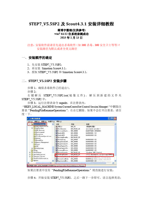
STEP7_V5.5SP2及Scout4.3.1安装详细教程蒋博宇整理(仅供参考)win7 64/32位系统亲测成功2015年1月13日注意:安装软件前请首先退出杀毒软件(如360杀毒、360安全卫士等等)!安装路径为默认或者全英文路径一、安装顺序的确定1、先安装STEP7_V5.5SP2;2、再安装Simotion Scout4.3.1;3、授权STEP7_V5.5SP2和Simotion Scout4.3.1;二、S TEP7_V5.5SP2安装步骤步骤1:确保杀毒软件已经退出!;步骤2:右键解压STEP7_V5.5SP2.iso(镜像文件),解压到新建的文件夹STEP7_V5.5SP2中;步骤3:运行注册表命令regedit,在注册表内:“HKEY_LOCAL_MACHINE\System\CurrentControlSet\Control\Session Manager\”中删除注册表“PendingFileRenameOperations”,右击它删除。
如果不会打开注册表,请百度一下。
如果注册表中没有“PendingFileRenameOperations”则直接进行安装;步骤4:开始安装STEP7_V5.5SP2,之后一路下一步即可,语言选择英语;注意点击Next。
经过一段时间之后,安装结束前,选择不重新启动计算机,于是STEP7_V5.5SP2就安装完成了!三、S imotion Scout4.3.1安装步骤步骤1:确认安装完成了STEP7_V5.5SP2;步骤2:直接点击setup,进行安装;如果出现下面所示对话框:则同STEP7_V5.5SP2安装步骤3所示方法解决:步骤3:一路点击“下一步”即可,最后经过漫长的等待,大约50分钟左右,安装结束,弹出一个对话框,点击“NO”,之后选择是否重新启动,随意!到此,Simotion Scout4.3.1安装完成。
四、授权STEP7_V5.5SP2和Simotion Scout4.3.1步骤1:首先下载授权工具,如下图所示:没有的话,在群共享下载,或者自行在网上找最新版本的;步骤2:双击授权工具,等到如下界面步骤3:STEP7_V5.5SP2授权步骤4:Simotion Scout4.3.1授权到此为止,软件就安装完成了。
Step7V5.4安装演示

有防火墙
点击确定
安装STEP7 V5.4 (中文版)软件: 大约需要20多分钟
点击下一步
点击下一步
重启电脑后,继续 安装STEP7 V5.4 (中文版)软件: 大约需要20分钟
接受协议
点击下一步
可输入用户名和组织
点击下一步
默认为典 型模式
默认安装路径
点击下一步
点击下一步
授权不选
点击下一步
以上有不当之处,请大家给与批评指正, 谢谢大家!
54
点击安装
正在安装
正在安装
正在安装
有防火墙
点击确定
继续安装
安装STEP7 V5.4 SP4(中文版)软 件:大约需要10多
分钟
继续安装
安装授权管理软件: 大约需要1分钟
点击确定
点击确定 点击关闭
点击是
点击跳过
重启计算机
重启后,卓面出现了 STEP7的快捷图标
STEP7软件没有授权 的效果
授权软件
授权安装位置 选择授权文件
点击安装
从桌面启动 STEP7
取消向导功能
安装仿真软件
点击OK
下一步
下一步
选择接受许可协议
点击下一步
点击下一步
默认为典 型模式
默认安装路径
点击下一步
点击下一步
跳过授权
点击下一步
点击安装
安装中
安装结束
确定后,重启计算机
仿真软件,启动快捷工具
SIMATIC STEP7 V5.4安装步骤
编程软件 仿真软件 授权软件
解压缩编程软件
安装源文件的路径必须为英文 点击安装文件
点击下一步
选择接受许可协议
TIA-Portal V15.1安装教程
1 / 14TIA-Protal 安装教程介绍本文档以TIA-Portal 软件V15.1版本为例,介绍TIA-Portal 软件的安装步骤,其他版本的TIA-Portal 软件安装步骤可参考本文档。
作者:分类: 内部教程 创建日期: 07/03/2019软件版本:V15.1文档版本:1.01、准备内容电脑,TIA-Portal V15.1软件安装包。
系统要求:win7及以上版本安装包内容:TIA Portal STEP 7 Professional WinCC Professional V15.1SIMATIC_S7-PLCSIM_V15_01_00_00SIMATIC WinCC Legacy Panel Images V15.12、安装TIA Portal STEP 7 Professional WinCC Professional V15.1软件2 / 143 / 14打开“TIA Portal STEP 7 Professional WinCC Professional V15.1”文件夹,双击“star ”应用程序图标,开始初始化……4 / 14初始化完成后进行安装语言选择,选择好之后点击“下一步。
”5 / 14进行产品语言选择,选择好之后点击“下一步。
”6 / 14进行产品配置选择,这里我们无需进行选择,按照默认配置就OK 直接点击“下一步”7 / 14进行授权许可后点击“下一步”8 / 14授权安全控制权限9 / 14概览页面,点击“安装”开始进行安装10 / 14软件安装中……11 / 14安装完成,选择“否,稍后重启计算机”12 / 14在电脑开始搜索栏输入“REGEDIT ”回车打开注册表编辑器,找到“HKEY_LOCAL_MACHINE\System\CurrentControlSet\Control\Session Manager\ ”的值“PendingFileRenameOperations”,删除这个值,退出注册表编辑器。
Step7v55CN中文版及PLCSIM仿真器下载安装步骤详解
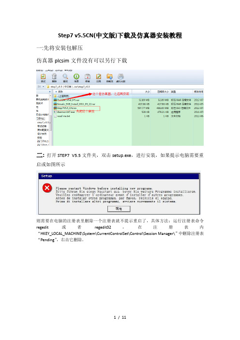
Step7 v5.5CN(中文版)下载及仿真器安装教程一:先将安装包解压仿真器plcsim文件没有可以另行下载二:打开STEP7 V5.5文件夹,双击setup.exe,进行安装,如果提示电脑需要重启或如图所示则需要在电脑的注册表里删除一个注册表就不提示重启了,具体方法:运行注册表命令regedit或者regedit32,在注册表内“HKEY_LOCAL_MACHINE\System\CurrentControlSet\Control\Session Manager\”中删除注册表“Pending”,右击它删除。
三、双击setup.exe之后,选择安装简体中文,如图下一步。
四、下一步选择接受,再下一步。
五、程序进入安装状态,大概会花费十几分钟。
进入逐个程序安装,到这里选择下一步。
在此选择典型安装,您可以选择安装到其他磁盘,下一步。
选择简体中文,下一步在此点击安装,程序会继续进行安装。
这里需要几分钟出现这个窗口点击PC Adapter然后安装,关闭选择立即重启电脑,重启完后再授权。
重启后电脑桌面上会多三个图标接下来对软件授权Windows 7:打开安装包中的这个文件完成上面三步点击ALL,完成即可下面是仿真器的安装,安装包中PLCSIM_V54_SP5这个文件仿真安装包,需要注意的是,安装时需将这个文件拷贝在之前step7安装路径下,找到common files 这个文件将文件拷贝在下面这个文件里打开安装之前先检查,之前这个注册表是否被删除,因为电脑重启后此文件将恢复,须重新删除再进行安装删除后即可安装安装完成后,打开step7软件,会发现下面这个图标由灰变亮了,表示可以使用仿真器可模拟接口关闭11 / 11。
网抵Managed Switch PSU安装指南说明书
Installation Guide OverviewThe following table provides an overview of the power supply units (PSUs) for managed switches and the models in which they are supported.PSU Model Used in SwitchModelAPS150W M4300-28GM4300-52GAPS250W M4300-8X8FM4300-12X12FM4300-24X24FAPS299W M4300-16XAPS550W M4300-28G-POE+M4300-52G-POE+APS600W M4300-96XM4300-16XAPS750W M4500-32CM4500-48XF8CAPS1000W M4300-28G-POE+M4300-52G-POE+M6100-3SRPS4000v2APS1200W M4300-96XInstall an additional power supply unitIn models with more than one power supply bay, you can install an additional PSU.1. Pull out the cover plate from the power module bay in which you want toinsert the additional PSU.AC OK LED. All PSUs provide one AC OKLED. During normal operation, this LEDlights green to indicate that the PSU isreceiving power.DC OK LED. Model APS150W also providesone DC OK LED. During normal operation,this LED lights green to indicate that the DCoutputs are within regulation limits.NETGEAR Power Supply Unitfor Managed SwitchesAPS150W, APS250W, APS299W, APS550W, APS600W,APS750W, APS1000W, and APS1200WPackage contents• Power supply unit• Power cord (varies by region)• Installation guide 2. Insert the additional PSU into the power module bay, and gently push thePSU into the bay.CAUTION: When inserting the PSU, do not use unnecessary force. Doing so can damage the connectors on the back of the PSU and on the midplane.3. Connect the end of the power cord to the power receptacle on the PSU.4. Plug the AC power cord into a power source such as a wall socket or powerstrip.When you apply power, the AC OK LED on the PSU lights. The LED on the switch for the power supply bay also lights. If these LEDs do not light, make sure that the power cord is plugged in and that the power source is good.Replace a power supply unitIn models with more than one PSU, the PSUs are hot-pluggable.1. If your switch functions with a single PSU only, disconnect the power cordfrom the PSU and let the switch power down.If your switch functions with more than one PSU, you do not need to power down the switch and you can perform a hot swap.2. Remove the PSU from the power module bay by moving the orange releaselatch to the left and pulling the extraction handle.3. Insert the replacement PSU into the power module bay, and gently push thePSU into the bay until the latch locks.CAUTION: When inserting the PSU, do not use unnecessary force. Doing so can damage the connectors on the back of the PSU and on the midplane. 4.Connect the end of the power cord to the power receptacle on the PSU.NETGEAR, Inc.350 East Plumeria DriveSan Jose, CA 95134, USANETGEAR INTERNATIONAL LTD Floor 1, Building 3University Technology Centre Curraheen Road, Cork, T12EF21, Ireland© NETGEAR, Inc., NETGEAR and the NETGEAR Logo are trademarks of NETGEAR, Inc. Any non‑NETGEAR trademarks are used for reference purposes only.November 20195. Plug the AC power cord into a power source such as a wall socket or powerstrip.When you apply power, the AC OK LED on the PSU lights. The LED on the switch for the power supply bay also lights. If these LEDs do not light, make sure that the power cord is plugged in correctly and that the power source is good.Technical specificationsSpecificationsPSUAC input• APS150W . 100–127VAC, 3A, 50–60 Hz or 200–240VAC, 1.5A, 50–60 Hz • APS250W . 100–240VAC, 3.5–2A, 50–60 Hz • APS299W . 100–240VAC, 5–2.5A, 50–60 Hz • APS550W . 100–240VAC, 9–4A, 50–60 Hz • APS600W . 90–132VAC, 8A, 47–63 Hz or 180–264VAC, 4A, 47–63 Hz • APS750W . 100–240VAC, 10/5.36A max, 50–60 Hz • APS1000W . 100–127VAC, 9.9A, 50–60 Hz or 200–240VAC, 7.8A, 50–60 Hz • APS1200W . 90–132VAC, 15A, 43–67 Hz or 180–264VAC, 8A, 43–67 HzDC output • APS150W . +12V, 12.5A• APS250W . +12V, 20A or +12 VSB 1A • APS299W . +54.5V, 5.51A• APS550W . +54V, 10.95A or +12 VSB 2.08A • APS600W . +54.5 VDC, 11A• APS750W . +12V, 61.5A or +12VSB 3A• APS1000W . 56V, 12.12A or +12 VSB 1.8A (@ 100–127VAC) 56V, 17.35A or +12 VSB 2.4A (@ 200–240VAC)• APS1200W . +54.5 VDC, 22A @ 230 VAC, or 18.35A @ 115 VACSpecificationsPSUDimensions (H x W x D)• APS150W . 1.5 x 2.0 x 7.3 in. (39 x 50.5 x 185 mm)• APS250W . 1.5 x 2.9 x 7.3 in. (39 x 74 x 185 mm)• APS299W . 1.5 x 2.9 x 7.6 in. (39 x 74 x 194 mm)• APS550W, APS1000W . 1.6 x 3.6 x 8.7 in. (40 x 87 x 208 mm)• APS600W, APS1200W . 1.6 x 2.9 x 7.3 in. (40 x 73 x 185 mm)• APS750W . 1.6 x 7.5 x 8.1 in. (40 x 192 x 206 mm)Operating temperature• APS250W . 32 to 122ºF (0 to 50ºC)• APS150W, APS299W, APS550W, APS600W, APS1000W , APS1200W . 23 to 122ºF (–5 to 50ºC)• APS750W . 32 to 131ºF (0 to 55ºC)Operating relative humidity• APS150W . Up to 95% noncondensing• APS250W, APS299W, APS550W, APS600W, APS1000W, APS1200W . 5% to 95% noncondensing • APS750W . 10 to 90% noncondensingOperating altitude level • APS250W, APS550W, APS1000W . Up to 9,800 feet (3,000 m) above sea level • APS150W , APS299W, APS600W, APS750W, APS1200W . Up to 16,000 feet (5,000 m) above sea levelStorage temperature• APS150W, APS250W, APS299W . –40 to 158ºF (–40 to 70ºC)• APS550W, APS600W, APS1000, APS1200W . –40 to 185ºF (–40 to 85ºC )Storagealtitude level Below 49,000 feet (15,000 m) above sea levelMTBFAll models except APS750W . 4,534,733 hrs (~517 years) @ 77ºF (25ºC)APS750W only . 200,000 hrs (~23 years) @ 122ºF (50ºC)SupportThank you for purchasing this NETGEAR product. You can visithttps:///support/ to register your product, get help, access the latest downloads and user manuals, and join our community. We recommend that you use only official NETGEAR support resources.Si ce produit est vendu au Canada, vous pouvez accéder à ce document en français canadien à https:///support/download/.(If this product is sold in Canada, you can access this document in Canadian French at https:///support/download/.)For regulatory compliance information including the EU Declaration of Conformity, visit https:///about/regulatory/.See the regulatory compliance document before connecting the power supply.Do not use this device outdoors. If you connect cables or devices that are outdoors to this device, see https:///000057103 for safety and warranty plianceSafetyIEC 60950-1, EN 60950-1, CB Certificate/Report, UL/CSA 60950-1CE Low Voltage Directive 2006/95/EC (Europe)CCC (China)KC (Korea)EMCCC / ICES-003 Emission (USA/Canada)CRISP 22 Emission (International)EN55022 Emission (Europe)EN55024 Immunity (Europe)EN61000-4-2 Electrostatic Discharge EN61000-4-3 Radiated RFI Immunity EN61000-4-4 Electrical Fast Transients level 4EN61000-4-5 Electrical Surge LevelEN61000-4-6 RF ConductedEN61000-4-8 Power Frequency Magnetic Fields EN61000-4-11 Voltage Dips and Interruptions EN61000-4-8 Power Frequency Magnetic Fields EN61000-4-11 Voltage Dips and Interruptions EN61000-3-2 Harmonics (Europe)EN61000-3-3 Voltage Flicker (Europe)。
wincc_7.0安装说明
wincc 7.0中文版安装方法标签:杂谈软件安装好之后大家最好重启下电脑,然后我们做2个步骤就可以了,视频比较麻烦的。
1,。
首先把硬狗破解文件覆盖下,(破解文件在G:\simatic wincc 7.0授权)破解USB硬狗具体操作方法如下:首先在任务管理器(打开点击ctrl+alt+delete)里查看一下,是否有CCLicenseService.exe进程在运行,如果有就先结束该进程,然后在C:\Program Files\Common Files\Siemens\BIN文件夹里找到CCLicenseService.exe文件(这是默认安装文件夹,如果您安装在其它分区,请在相应分区里找),将其重命名保存(如改为CCLicenseService0.exe或CCLicenseService-old.exe等),然后将附件同名文件放到该文件夹里即可。
现在运行WINCC试试有什么变化?当然,您需要先安装软授权,像其它版本一样。
如果运行有任何问题,可以将内存里的CCLicenseService.exe进程结束,然后恢复原文件即可。
安装方法:wincc v7.21、安装windows组件:Message Quering(消息队列) 和IIS2、用虚拟光驱装载ISO文件,运行WinCC_V70_SP2.exe3、出现安装程序的对话框后,不要按任何按钮4、在C盘根目录下,找临时文件夹C:\{NUMBERS-NUMBERS-....} 例如:{DFDBB8FE-7426-454A-937C-F8E9230F896A}5、在该文件夹内,找到Properties_SiWA.ini文件,用记事本打开,修改其中[Conditions] 段:原来为:[Conditions]Action1=ExtractAction1Condition=Condition1 AND Condition2 AND Condition3 (本行需要修改)Condition1 .... (本行删除)Condition2 .... (本行删除)Condition3 ..... (本行删除)修改后为:[Conditions]Action1=ExtractAction1Condition=然后存盘。
20D-IN010B-EN-P SynchLink Board 安装指南
Installation Instructions20D-IN010B-EN-P SynchLink ™ Board for PowerFlex ® 700S Drives with Phase II ControlWhat This Kit ContainsVerify that your kit contains the items listed in the following table. If your kit does not contain the correct items, contact your Rockwell Automation sales representative.Tools That You Need•Phillips ® screwdriver •POZIDRIV® screwdriver •Standard (flat blade) screwdriver Phillips ® and POZIDRIV® are registered trademarks of Phillips Screw CompanyATTENTION: To avoid an electric shock hazard, verify that the voltage on the bus capacitors has discharged before performing any work on the drive. Measure the DC bus voltage at the +DC & –DC terminals of the Power Terminal Block (DC+ & DC- in high power drives). The voltage must be zero.ATTENTION: HOT surfaces can cause severe burns. Do not touch the heatsink surface during operation of the drive. After disconnecting power allow time for cooling.ATTENTION: Hazard of permanent eye damage exists when using optical transmission equipment. This product emits intense light and invisible radiation. Do not look into module ports or fiber-optic cable connectors.ATTENTION: This drive contains ESD (Electrostatic Discharge) sensitive parts and assemblies. Static control precautions are required when installing, testing, servicing or repairing this assembly. Component damage may result if ESD control procedures are not followed. If you are not familiar with static control procedures, reference A-B publication 8000-4.5.2, “Guarding Against Electrostatic Damage” or any other applicable ESD protection handbook.Quantity:Description 1SynchLink Board 1“Stacker” connector 2Screws 2Stand-offsSynchLink™ Board for PowerFlex® 700S Drives with Phase II ControlWhat You Need to Do T o install or replace a SynchLink board, complete the following steps:❐ Step 1: Remove power from the drive.❐ Step 2: Open/Remove the drive cover(s).❐ Step 3: Remove the control cassette from the drive.❐ Step 4: Remove the inside cover from the control cassette.❐ Step 5:Remove the existing SynchLink board.❐ Step 6: Install the new SynchLink board.❐ Step 7: Install the control cassette inside cover.❐ Step 8:Install the control cassette in the drive.❐ Step 9: Connect the SynchLink cables.❐ Step 10:Close/Install the drive cover(s).❐ Step 11:Document the change.Step 1:Remove Powerfrom the Drive ATTENTION: To avoid an electric shock hazard, verify that the voltage onthe bus capacitors has discharged before performing any work on thedrive. Measure the DC bus voltage at the +DC & –DC terminals of thePower Terminal Block. The voltage must be zero.Remove power before making or breaking cable connections. When youremove or insert a cable connector with power applied, an electrical arcmay occur. An electrical arc can cause personal injury or property damageby:•sending an erroneous signal to your system’s field devices, causingunintended machine motion•causing an explosion in a hazardous environmentElectrical arcing causes excessive wear to contacts on both the moduleand its mating connector. Worn contacts may create electrical resistance.2Rockwell Automation Publication 20D-IN010B-EN-P - November 2010Rockwell Automation Publication 20D-IN010B-EN-P - November 20103SynchLink™ Board for PowerFlex® 700S Drives with Phase II ControlStep 2:Open/Remove the Drive Cover(s)Frames 1 (6)•Frames 1…4: Locate the slot in the upper left corner. Slide the locking tab up and swing the cover open.•Frame 5: Slide the locking tab up, loosen the right-hand cover screw and remove the cover.•Frame 6: Loosen the two screws on the bottom drive cover and slide the bottom cover down and out. Loosen the two screws on the top cover and remove the cover.Frames 9 (14)•Frame 9: Remove the eight POZIDRIV screws that secure the top cover to the drive and remove the cover.•Frame 10…14: Open the enclosure door on the bay that holds the controlframe.Frames 1 (4)Frame 5Frame 6Frame 9SynchLink™ Board for PowerFlex® 700S Drives with Phase II ControlStep 3:Remove the Control Cassette from the Drive Frames 1 (6)See page3 for Frames 9…14 control cassette removal instructions.1.If necessary, disconnect any fiber-optic ControlNet and SynchLink cablesfrom the control assembly.2.Disconnect any remaining I/O and communications cables from thecontrol assembly.3.Disconnect the ribbon cables that connect to the main control board.4.Loosen the two screws on the front of the cassette.5.Remove the cassette from the drive chassis.ATTENTION: Hazard of permanent eye damage exists when using opticaltransmission equipment. This product emits intense light and invisibleradiation. Do not look into fiber-optic ports or fiber-optic cable connectors.cassette4Rockwell Automation Publication 20D-IN010B-EN-P - November 2010Rockwell Automation Publication 20D-IN010B-EN-P - November 20105SynchLink™ Board for PowerFlex® 700S Drives with Phase II ControlFrames 9 (14)1.If necessary, disconnect any fiber-optic ControlNet and SynchLink cables from the control assembly.2.Disconnect any remaining I/O and communications cables from the control assembly.3.Disconnect the ribbon cables from the main control board.4.Loosen the captive screw on the control assembly mounting plate and swing the control assembly mounting plate away from the control frame.ATTENTION: Hazard of permanent eye damage exists when using opticaltransmission equipment. This product emits intense light and invisible radiation. Do not look into fiber-optic ports or fiber-optic cable connectors.mounting plate away from drive.SynchLink™ Board for PowerFlex® 700S Drives with Phase II Control5.Loosen the two mounting screws on the front of the control assembly andslide the control cassette off the mounting bracket.Step 4:Remove the Inside Cover from the Control Cassette •Loosen the three screws on the face of the front cover and remove the cover.6Rockwell Automation Publication 20D-IN010B-EN-P - November 2010SynchLink™ Board for PowerFlex® 700S Drives with Phase II ControlStep 5:Remove the Existing SynchLink Board If you are installing a new SynchLink board only, continue with Step 6: Install the New SynchLink Board on page8.If you are replacing an existing SynchLink board continue with these steps.1.Remove the two screws that secure the SynchLink board to the standoffson the main control board and remove the SynchLink board from thestacker connector.2.Remove the stacker connector from the mating connector on the maincontrol board.3.Remove the two standoffs from the main control board.Rockwell Automation Publication 20D-IN010B-EN-P - November 20107SynchLink™ Board for PowerFlex® 700S Drives with Phase II ControlStep 6:Install the New SynchLink Board 1.Secure the two standoffs to the main control board. Tighten to 0.8… 1.1N•m (7…10 lb•in).2.Insert the short pins of the stacker connector into the mating connector onthe main control board. See the Important statement below.3.Connect the mating connectors of the new SynchLink board to the longpins of the stacker connector. See the Important statement below.4.Secure the SynchLink board to the standoffs using the two screwsprovided. Tighten to 0.8… 1.1 N•m (7…10 lb•in).Step 7:Install the Control Cassette Inside Cover Install the control cassette inside cover in the reverse order of removal. Refer to Step 4: Remove the Inside Cover from the Control Cassette on page6.IMPORTANT The end of the stacker connector with the short pinsmust connect to the main control board. The end ofthe stacker connector with the long pins must connectto the SynchLink board.Main control boardmating connector8Rockwell Automation Publication 20D-IN010B-EN-P - November 2010Rockwell Automation Publication 20D-IN010B-EN-P - November 20109SynchLink™ Board for PowerFlex® 700S Drives with Phase II ControlStep 8:Install the Control Cassette in the DriveInstall the control cassette in the reverse order of removal. Refer to Step 3: Remove the Control Cassette from the Drive on page 4.Step 9:Connect the SynchLink Cables Class 1 LED Product•Connect the fiber-optic cables to the J1 (transmit) and J2 (receive) connectors on the SynchLink board. Push the plug into the socket until it produces an audible click.ATTENTION: Hazard of permanent eye damage exists when using opticaltransmission equipment. This product emits intense light and invisible radiation. Do not look into module ports or fiber-optic cable connectors.IMPORTANT Minimum inside bend radius for SynchLink fiber-optic cable is 25.4 mm (1 in.). Any bends with a shorter inside radius can permanently damage the fiber-optic cable. Signal attenuation increases withdecreased inside bend radii.IMPORTANT Do not overtighten tie-wraps.SynchLink™ Board for PowerFlex® 700S Drives with Phase II ControlStep 10:Close/Install the Drive Cover(s)Close/Install the drive cover(s) in the reverse of removal. Refer to Step 2: Open/ Remove the Drive Cover(s)on page3.Step 11:Document the Change Document the SynchLink board installation on the “Field Installed Options” label. Use the blank line if you are installing the SynchLink board in a drive that was manufactured without it.TIP Use the packing material from the new SynchLink board to return the replaced SynchLink board.10Rockwell Automation Publication 20D-IN010B-EN-P - November 2010Rockwell Automation Publication 20D-IN010B-EN-P - November 201011SynchLink™ Board for PowerFlex® 700S Drives with Phase II ControlAdditional Information Refer to The SynchLink Design Guide , publication 1756-TD008, when planningand connecting the SynchLink network.Table 1 - SynchLink Cables and AccessoriesTable 2 - Fiber-Optic Cable Assembly Specifications Description Cat. No.3 M Fiber-Optic Link (Qty 2)1403-CF 0035 M Fiber-Optic Link (Qty 2)1403-CF 00510 M Fiber-Optic Link (Qty 2)1403-CF 010500 M Fiber-Optic Bulk 1403-CF BLK Termination Kit 1403-NTOLConnector (Qty 10) 1403-N10Splice Bushing (Qty 5) 1403-N11Pulling Bullet 1403-N12Fiber Stripper Tool 1403-N13SynchLink Fiber-Hub, 1 input, Base 1751-SLBASynchLink Fiber-Hub, 4 output, “Star” Splitter 1751-SL4SPSynchLink Bypass Switch 1751-SLBP/AParameterValue Connecting Cables 200/230 micron HCS (Hard Clad Silica)Versalink V-SystemLucent Technologies,Specialty Fibers Technology DivisionMaximum Cable Length 300 meters with no more than one splice or one adapterMinimum Cable Length 1 meterMinimum inside bend radius 25.4mm (1 in.). Any bends with a shorter inside radius can permanentlydamage the fiber-optic cable. Signal attenuation increases withdecreased inside bend radii.Operating Wavelength 650 nm (Red)Data Rate 5 MbpsMaximum Node Count 10 - Daisy Chain256 - Star ConfigurationU.S.Allen-BradleyDrivesTechnicalSupport-Tel:(1)262.512.8176,Fax:(1)262.512.2222,E-mail:*****************,Online:/support/abdrivesPublication 20D-IN010B-EN-P – November 2010PN-92652 Supersedes 20D-IN010A-EN-P –July 2004Copyright © 2010 Rockwell Automation, Inc. All rights reserved. Printed in USA.。
最新版SC封装win7超详细图文教程
最新版SC封装工具的使用及win7封装超详细图文教程SC封装工具以其卓越的安全性,操作的便捷性收买了很多技术员的心,使之跟老牌封装工具ES比起来也只有过无不及,那么今天教大家学习最新发布的sc封装图文教程,下面开始今天的教程,教程写的比较详细,相信大家都能看懂,虚拟机用的是最新版的VMWARE 11所需软件资源下载:1:VMWARE WorkStation 11 虚拟机2:SC封装工具3:OEM7小马激活工具4:SC的win7专用母盘5:天空的U盘助理PE系统6:万能驱动助理V6.2x327 : 万能驱动助理V6.2x648:SC运行库下面教程正式开始,关于vmware workstation 11虚拟机的安装请点击查看安装激活教程,这里就不在阐述了,点击这个“+”加号新建一个虚拟机。
选择“典型”选择稍后安装操作系统,点击“下一步”客户机操作系统选择“Microsoft Windows”,版本选择“Windows 7 ”虚拟机名称和虚拟机的存放位置,大家可以随意更改,便于识别就可以了。
磁盘大小默认60G足够了,建议不要更改了,然后选择“将虚拟磁盘存储为单个文件”,点“下一步”点击“完成”按钮,结束新建虚拟机的过程。
选择“编辑虚拟机”将红框圈出的硬件全部移除,这是最小系统的步骤,旨在于提高系统的兼容性。
然后点“完成”按钮。
回到虚拟机主界面,点击“CD/DVD(SATA)”选项选择下面的“使用ISO映像文件”,选择加载前面下载的PE系统。
点击主菜单上面的绿色三角然后选择下拉列表框的“打开电源时进入固件”选项进入PE系统以后,运行桌面的DiskGenius分区工具,按下图进行分区。
一般分两个区即可,数值默认就行了。
分好去以后,先关闭虚拟机,CD/DVD加载您之前下载的win7母盘系统,出现如下界面时立马按下回车键,出现母盘安装界面。
点“下一步”选择“现在安装”按钮。
根据需要选择32位还是64位的系统,点“下一步”勾选“我接受许可条款”,点“下一步”选择第二个“自定义”选项系统安装分区选择第一个也就是C盘,然后选择“驱动器选项(高级)”选择“格式化”,把C盘格式化一下。