rfc2674.Definitions of Managed Objects for Bridges with Traffic Classes, Multicast Filtering and Vir
网络管理-复习资料

4、简述网络管理的基本模型以及各个组成部分的功能。
网络管理的基本模型是管理-代理者模型,它主要包括4个组成部分:(1)管理者:位于网络主干或接近主干的工作站或微机上的软件,负责发出管理操作命令、接受来自代理的信息并对信息进行处理,以确定网络状态是否正常。
(2)管理代理:位于主机、网络互连设备等被管理设备内部的软件,接受管理者发出的命令并完成相应的操作,例如更改被管理设备的配置或返回所在设备的信息。
(3)网络管理协议:管理者和管理代理之间进行信息交换的通信约定。
(4)管理信息库:简称MIB,是一个概念上的数据集合,它由代理软件进行管理,其中存放了描述被管理设备的管理对象,MIB将管理对象组织为分层树形结构,而管理对象使用管理信息结构(SMI)进行定义。
MIB属于逻辑数据库,在内存中并没有数据集合的完整副本。
代理软件收到命令后,提取命令中的对象标识符,然后根据对象标识符去读取对应的硬件信息,并将该信息返回给管理者。
4.1什么是对象标识符?对象标识符(OID)是用于全局唯一标识管理对象的数字序列,使用点分十进制表示。
管理对象被组织成分层树形结构,树的叶子结点表示管理对象。
树中的每个结点都有编号,从根到每个叶子结点都有唯一的路径,将路径上所有结点的编号按顺序以点分十进制的方法写出来,即为对象标识符。
5、MIB库中包含了哪些信息?MIB中的数据可以分为感测数据、结构数据和控制数据三类。
感测数据用于表示测量到的网络状态;结构数据描述网络物理和逻辑的组成;控制数据存储网络的操作配置。
6、什么是ASN.1?它有什么作用?ASN.1的全称是抽象语法表示,它是一种形式语言,提供统一的网络数据表示,通常用于定义应用数据的抽象语法和应用层协议数据单元(PDU)的结构。
7、什么是BER编码?它的作用是什么?BER称为基本编码规则,用于将ASN.1表示的数据按照一定规则转换为二进制位串。
8、简述应用实体、表示实体和抽象语法、传输语法之间的关系。
中国铁塔动环监控系统统一互联B接口技能技术总结规范

精心整理主题:铁塔集团、B接口规范、铁塔B接口规范中国铁塔动环监控系统统一互联B接口技术规范3.3通信协议—CommunicationProtocol.....................................3.4B接口—BInterface...................................................3.5监控对象—SupervisionObject(SO).....................................3.6监控点—SupervisionPoint(SP)........................................3.7数据流接口..........................................................4.接口.....................................................................5.B接口互联规范...........................................................5.1B接口互联...........................................................5.2B接口报文协议.......................................................6.FTP接口能力.............................................................7.FSU初始化能力...........................................................8.FSU自动升级能力.........................................................12YDT1363.2-2014通信局(站)电源、空调及环境集中监控管理系统第2部分:互联协议中国铁塔动环监控系统统一编码及命名规范V1.0中国铁塔动环监控系统统一信号字典表V1.03.定义下列术语和定义适用于本文件。
铁路通信传输与接入网工程设计规范

铁路通信传输及接入网工程设计规1总则1.0.1 为统一铁路通信传输及接入网工程的设计标准,提高工程设计质量,制定本规。
1.0.2 本规适用于新建、改建的铁路传输及接入网系统工程建设。
1.0.3 铁路通信传输及接入网工程设计应贯彻国家和铁路基本建设方针、政策,符合铁路运输生产和提高现代化管理水平的需要。
1.0.4 铁路通信传输及接入网工程建设应遵循技术先进、经济适用、安全可靠和统一标准(制式)、符合运输、合理布局、互联互通、资源共享的原则。
新建和改建的工程都应做好与既有铁路通信网的衔接,合理利用既有资源。
条文说明:铁路通信传输系统是一个全程全网的系统。
任何新建的通信传输系统都不会是一个孤立的系统,它总是要与其他网络(包括传输网络)互联,信息要进行交换。
因此,新建和改建的工程都应做好与既有铁路通信网的衔接,合理利用既有资源,这部分也是设计应重点关注和考虑的问题。
1.0.5 作为铁路通信各种业务的基础承载平台,铁路通信传输及接入网应结合通信技术发展的主流,向传输数字化、管理智能化、业务多样化发展。
1.0.6 铁路通信传输及接入网工程设计应与业务需求和发展规划相适应,以近期业务需求为主,兼顾远期业务发展。
机房等不易改、扩建的基础设施宜按远期设计,电源等宜按近期设计,系统其他设备可按交付运营后五年设计。
条文说明:铁路通信传输及接入网工程以设备为主,而且投资相对较大,因此不宜按照初期考虑,应适当考虑延长设备的使用寿命,但也要结合产品的更新换代速度,因此综合以上因素考虑,设计年度按照近期为宜。
通信机房、外电等不易扩容的基础设施宜按照远期考虑。
1.0.7 铁路通信传输及接入网工程设计除应符合本规外,尚应符合《铁路运输通信设计规》(TB 10006)和国家现行有关标准的相关规定。
2术语和符号2.1术语2.1.1 铁路通信 railway communication用于铁路运输组织、客货营销、经营管理等方面信息传输与交换的各种通信系统的总称。
rfc2401.Security Architecture for the Internet Protocol
Network Working Group S. Kent Request for Comments: 2401 BBN Corp Obsoletes: 1825 R. Atkinson Category: Standards Track @Home Network November 1998 Security Architecture for the Internet ProtocolStatus of this MemoThis document specifies an Internet standards track protocol for the Internet community, and requests discussion and suggestions forimprovements. Please refer to the current edition of the "InternetOfficial Protocol Standards" (STD 1) for the standardization stateand status of this protocol. Distribution of this memo is unlimited.Copyright NoticeCopyright (C) The Internet Society (1998). All Rights Reserved.Table of Contents1. Introduction (3)1.1 Summary of Contents of Document (3)1.2 Audience (3)1.3 Related Documents (4)2. Design Objectives (4)2.1 Goals/Objectives/Requirements/Problem Description (4)2.2 Caveats and Assumptions (5)3. System Overview (5)3.1 What IPsec Does (6)3.2 How IPsec Works (6)3.3 Where IPsec May Be Implemented (7)4. Security Associations (8)4.1 Definition and Scope (8)4.2 Security Association Functionality (10)4.3 Combining Security Associations (11)4.4 Security Association Databases (13)4.4.1 The Security Policy Database (SPD) (14)4.4.2 Selectors (17)4.4.3 Security Association Database (SAD) (21)4.5 Basic Combinations of Security Associations (24)4.6 SA and Key Management (26)4.6.1 Manual Techniques (27)4.6.2 Automated SA and Key Management (27)4.6.3 Locating a Security Gateway (28)4.7 Security Associations and Multicast (29)Kent & Atkinson Standards Track [Page 1]5. IP Traffic Processing (30)5.1 Outbound IP Traffic Processing (30)5.1.1 Selecting and Using an SA or SA Bundle (30)5.1.2 Header Construction for Tunnel Mode (31)5.1.2.1 IPv4 -- Header Construction for Tunnel Mode (31)5.1.2.2 IPv6 -- Header Construction for Tunnel Mode (32)5.2 Processing Inbound IP Traffic (33)5.2.1 Selecting and Using an SA or SA Bundle (33)5.2.2 Handling of AH and ESP tunnels (34)6. ICMP Processing (relevant to IPsec) (35)6.1 PMTU/DF Processing (36)6.1.1 DF Bit (36)6.1.2 Path MTU Discovery (PMTU) (36)6.1.2.1 Propagation of PMTU (36)6.1.2.2 Calculation of PMTU (37)6.1.2.3 Granularity of PMTU Processing (37)6.1.2.4 PMTU Aging (38)7. Auditing (39)8. Use in Systems Supporting Information Flow Security (39)8.1 Relationship Between Security Associations and Data Sensitivity.40 8.2 Sensitivity Consistency Checking (40)8.3 Additional MLS Attributes for Security Association Databases (41)8.4 Additional Inbound Processing Steps for MLS Networking (41)8.5 Additional Outbound Processing Steps for MLS Networking (41)8.6 Additional MLS Processing for Security Gateways (42)9. Performance Issues (42)10. Conformance Requirements (43)11. Security Considerations (43)12. Differences from RFC 1825 (43)Acknowledgements (44)Appendix A -- Glossary (45)Appendix B -- Analysis/Discussion of PMTU/DF/Fragmentation Issues (48)B.1 DF bit (48)B.2 Fragmentation (48)B.3 Path MTU Discovery (52)B.3.1 Identifying the Originating Host(s) (53)B.3.2 Calculation of PMTU (55)B.3.3 Granularity of Maintaining PMTU Data (56)B.3.4 Per Socket Maintenance of PMTU Data (57)B.3.5 Delivery of PMTU Data to the Transport Layer (57)B.3.6 Aging of PMTU Data (57)Appendix C -- Sequence Space Window Code Example (58)Appendix D -- Categorization of ICMP messages (60)References (63)Disclaimer (64)Author Information (65)Full Copyright Statement (66)Kent & Atkinson Standards Track [Page 2]1. Introduction1.1 Summary of Contents of DocumentThis memo specifies the base architecture for IPsec compliantsystems. The goal of the architecture is to provide various security services for traffic at the IP layer, in both the IPv4 and IPv6environments. This document describes the goals of such systems,their components and how they fit together with each other and intothe IP environment. It also describes the security services offered by the IPsec protocols, and how these services can be employed in the IP environment. This document does not address all aspects of IPsec architecture. Subsequent documents will address additionalarchitectural details of a more advanced nature, e.g., use of IPsecin NAT environments and more complete support for IP multicast. The following fundamental components of the IPsec security architectureare discussed in terms of their underlying, required functionality.Additional RFCs (see Section 1.3 for pointers to other documents)define the protocols in (a), (c), and (d).a. Security Protocols -- Authentication Header (AH) andEncapsulating Security Payload (ESP)b. Security Associations -- what they are and how they work,how they are managed, associated processingc. Key Management -- manual and automatic (The Internet KeyExchange (IKE))d. Algorithms for authentication and encryptionThis document is not an overall Security Architecture for theInternet; it addresses security only at the IP layer, providedthrough the use of a combination of cryptographic and protocolsecurity mechanisms.The keywords MUST, MUST NOT, REQUIRED, SHALL, SHALL NOT, SHOULD,SHOULD NOT, RECOMMENDED, MAY, and OPTIONAL, when they appear in this document, are to be interpreted as described in RFC 2119 [Bra97].1.2 AudienceThe target audience for this document includes implementers of thisIP security technology and others interested in gaining a generalbackground understanding of this system. In particular, prospective users of this technology (end users or system administrators) arepart of the target audience. A glossary is provided as an appendix Kent & Atkinson Standards Track [Page 3]to help fill in gaps in background/vocabulary. This document assumes that the reader is familiar with the Internet Protocol, relatednetworking technology, and general security terms and concepts.1.3 Related DocumentsAs mentioned above, other documents provide detailed definitions ofsome of the components of IPsec and of their inter-relationship.They include RFCs on the following topics:a. "IP Security Document Roadmap" [TDG97] -- a documentproviding guidelines for specifications describing encryption and authentication algorithms used in this system.b. security protocols -- RFCs describing the AuthenticationHeader (AH) [KA98a] and Encapsulating Security Payload (ESP) [KA98b] protocols.c. algorithms for authentication and encryption -- a separateRFC for each algorithm.d. automatic key management -- RFCs on "The Internet KeyExchange (IKE)" [HC98], "Internet Security Association andKey Management Protocol (ISAKMP)" [MSST97],"The OAKLEY KeyDetermination Protocol" [Orm97], and "The Internet IPSecurity Domain of Interpretation for ISAKMP" [Pip98].2. Design Objectives2.1 Goals/Objectives/Requirements/Problem DescriptionIPsec is designed to provide interoperable, high quality,cryptographically-based security for IPv4 and IPv6. The set ofsecurity services offered includes access control, connectionlessintegrity, data origin authentication, protection against replays (a form of partial sequence integrity), confidentiality (encryption),and limited traffic flow confidentiality. These services areprovided at the IP layer, offering protection for IP and/or upperlayer protocols.These objectives are met through the use of two traffic securityprotocols, the Authentication Header (AH) and the EncapsulatingSecurity Payload (ESP), and through the use of cryptographic keymanagement procedures and protocols. The set of IPsec protocolsemployed in any context, and the ways in which they are employed,will be determined by the security and system requirements of users, applications, and/or sites/organizations.When these mechanisms are correctly implemented and deployed, theyought not to adversely affect users, hosts, and other Internetcomponents that do not employ these security mechanisms forKent & Atkinson Standards Track [Page 4]protection of their traffic. These mechanisms also are designed tobe algorithm-independent. This modularity permits selection ofdifferent sets of algorithms without affecting the other parts of the implementation. For example, different user communities may selectdifferent sets of algorithms (creating cliques) if required.A standard set of default algorithms is specified to facilitateinteroperability in the global Internet. The use of thesealgorithms, in conjunction with IPsec traffic protection and keymanagement protocols, is intended to permit system and applicationdevelopers to deploy high quality, Internet layer, cryptographicsecurity technology.2.2 Caveats and AssumptionsThe suite of IPsec protocols and associated default algorithms aredesigned to provide high quality security for Internet traffic.However, the security offered by use of these protocols ultimatelydepends on the quality of the their implementation, which is outside the scope of this set of standards. Moreover, the security of acomputer system or network is a function of many factors, includingpersonnel, physical, procedural, compromising emanations, andcomputer security practices. Thus IPsec is only one part of anoverall system security architecture.Finally, the security afforded by the use of IPsec is criticallydependent on many aspects of the operating environment in which theIPsec implementation executes. For example, defects in OS security, poor quality of random number sources, sloppy system managementprotocols and practices, etc. can all degrade the security providedby IPsec. As above, none of these environmental attributes arewithin the scope of this or other IPsec standards.3. System OverviewThis section provides a high level description of how IPsec works,the components of the system, and how they fit together to providethe security services noted above. The goal of this description isto enable the reader to "picture" the overall process/system, see how it fits into the IP environment, and to provide context for latersections of this document, which describe each of the components inmore detail.An IPsec implementation operates in a host or a security gatewayenvironment, affording protection to IP traffic. The protectionoffered is based on requirements defined by a Security PolicyDatabase (SPD) established and maintained by a user or systemadministrator, or by an application operating within constraintsKent & Atkinson Standards Track [Page 5]established by either of the above. In general, packets are selected for one of three processing modes based on IP and transport layerheader information (Selectors, Section 4.4.2) matched against entries in the database (SPD). Each packet is either afforded IPsec security services, discarded, or allowed to bypass IPsec, based on theapplicable database policies identified by the Selectors.3.1 What IPsec DoesIPsec provides security services at the IP layer by enabling a system to select required security protocols, determine the algorithm(s) to use for the service(s), and put in place any cryptographic keysrequired to provide the requested services. IPsec can be used toprotect one or more "paths" between a pair of hosts, between a pairof security gateways, or between a security gateway and a host. (The term "security gateway" is used throughout the IPsec documents torefer to an intermediate system that implements IPsec protocols. For example, a router or a firewall implementing IPsec is a securitygateway.)The set of security services that IPsec can provide includes accesscontrol, connectionless integrity, data origin authentication,rejection of replayed packets (a form of partial sequence integrity), confidentiality (encryption), and limited traffic flowconfidentiality. Because these services are provided at the IPlayer, they can be used by any higher layer protocol, e.g., TCP, UDP, ICMP, BGP, etc.The IPsec DOI also supports negotiation of IP compression [SMPT98],motivated in part by the observation that when encryption is employed within IPsec, it prevents effective compression by lower protocollayers.3.2 How IPsec WorksIPsec uses two protocols to provide traffic security --Authentication Header (AH) and Encapsulating Security Payload (ESP). Both protocols are described in more detail in their respective RFCs [KA98a, KA98b].o The IP Authentication Header (AH) [KA98a] providesconnectionless integrity, data origin authentication, and anoptional anti-replay service.o The Encapsulating Security Payload (ESP) protocol [KA98b] may provide confidentiality (encryption), and limited traffic flow confidentiality. It also may provide connectionlessKent & Atkinson Standards Track [Page 6]integrity, data origin authentication, and an anti-replayservice. (One or the other set of these security servicesmust be applied whenever ESP is invoked.)o Both AH and ESP are vehicles for access control, based on the distribution of cryptographic keys and the management oftraffic flows relative to these security protocols.These protocols may be applied alone or in combination with eachother to provide a desired set of security services in IPv4 and IPv6. Each protocol supports two modes of use: transport mode and tunnelmode. In transport mode the protocols provide protection primarilyfor upper layer protocols; in tunnel mode, the protocols are applied to tunneled IP packets. The differences between the two modes arediscussed in Section 4.IPsec allows the user (or system administrator) to control thegranularity at which a security service is offered. For example, one can create a single encrypted tunnel to carry all the traffic between two security gateways or a separate encrypted tunnel can be createdfor each TCP connection between each pair of hosts communicatingacross these gateways. IPsec management must incorporate facilities for specifying:o which security services to use and in what combinationso the granularity at which a given security protection should be appliedo the algorithms used to effect cryptographic-based securityBecause these security services use shared secret values(cryptographic keys), IPsec relies on a separate set of mechanismsfor putting these keys in place. (The keys are used forauthentication/integrity and encryption services.) This documentrequires support for both manual and automatic distribution of keys. It specifies a specific public-key based approach (IKE -- [MSST97,Orm97, HC98]) for automatic key management, but other automated keydistribution techniques MAY be used. For example, KDC-based systems such as Kerberos and other public-key systems such as SKIP could beemployed.3.3 Where IPsec May Be ImplementedThere are several ways in which IPsec may be implemented in a host or in conjunction with a router or firewall (to create a securitygateway). Several common examples are provided below:a. Integration of IPsec into the native IP implementation. This requires access to the IP source code and is applicable toboth hosts and security gateways.Kent & Atkinson Standards Track [Page 7]b. "Bump-in-the-stack" (BITS) implementations, where IPsec isimplemented "underneath" an existing implementation of an IP protocol stack, between the native IP and the local networkdrivers. Source code access for the IP stack is not required in this context, making this implementation approachappropriate for use with legacy systems. This approach, when it is adopted, is usually employed in hosts.c. The use of an outboard crypto processor is a common designfeature of network security systems used by the military, and of some commercial systems as well. It is sometimes referred to as a "Bump-in-the-wire" (BITW) implementation. Suchimplementations may be designed to serve either a host or agateway (or both). Usually the BITW device is IPaddressable. When supporting a single host, it may be quite analogous to a BITS implementation, but in supporting arouter or firewall, it must operate like a security gateway.4. Security AssociationsThis section defines Security Association management requirements for all IPv6 implementations and for those IPv4 implementations thatimplement AH, ESP, or both. The concept of a "Security Association" (SA) is fundamental to IPsec. Both AH and ESP make use of SAs and a major function of IKE is the establishment and maintenance ofSecurity Associations. All implementations of AH or ESP MUST support the concept of a Security Association as described below. Theremainder of this section describes various aspects of SecurityAssociation management, defining required characteristics for SApolicy management, traffic processing, and SA management techniques.4.1 Definition and ScopeA Security Association (SA) is a simplex "connection" that affordssecurity services to the traffic carried by it. Security servicesare afforded to an SA by the use of AH, or ESP, but not both. Ifboth AH and ESP protection is applied to a traffic stream, then two(or more) SAs are created to afford protection to the traffic stream. To secure typical, bi-directional communication between two hosts, or between two security gateways, two Security Associations (one in each direction) are required.A security association is uniquely identified by a triple consisting of a Security Parameter Index (SPI), an IP Destination Address, and a security protocol (AH or ESP) identifier. In principle, theDestination Address may be a unicast address, an IP broadcastaddress, or a multicast group address. However, IPsec SA management mechanisms currently are defined only for unicast SAs. Hence, in the Kent & Atkinson Standards Track [Page 8]discussions that follow, SAs will be described in the context ofpoint-to-point communication, even though the concept is applicablein the point-to-multipoint case as well.As noted above, two types of SAs are defined: transport mode andtunnel mode. A transport mode SA is a security association betweentwo hosts. In IPv4, a transport mode security protocol headerappears immediately after the IP header and any options, and beforeany higher layer protocols (e.g., TCP or UDP). In IPv6, the security protocol header appears after the base IP header and extensions, but may appear before or after destination options, and before higherlayer protocols. In the case of ESP, a transport mode SA providessecurity services only for these higher layer protocols, not for the IP header or any extension headers preceding the ESP header. In the case of AH, the protection is also extended to selected portions ofthe IP header, selected portions of extension headers, and selectedoptions (contained in the IPv4 header, IPv6 Hop-by-Hop extensionheader, or IPv6 Destination extension headers). For more details on the coverage afforded by AH, see the AH specification [KA98a].A tunnel mode SA is essentially an SA applied to an IP tunnel.Whenever either end of a security association is a security gateway, the SA MUST be tunnel mode. Thus an SA between two security gateways is always a tunnel mode SA, as is an SA between a host and a security gateway. Note that for the case where traffic is destined for asecurity gateway, e.g., SNMP commands, the security gateway is acting as a host and transport mode is allowed. But in that case, thesecurity gateway is not acting as a gateway, i.e., not transitingtraffic. Two hosts MAY establish a tunnel mode SA betweenthemselves. The requirement for any (transit traffic) SA involving a security gateway to be a tunnel SA arises due to the need to avoidpotential problems with regard to fragmentation and reassembly ofIPsec packets, and in circumstances where multiple paths (e.g., viadifferent security gateways) exist to the same destination behind the security gateways.For a tunnel mode SA, there is an "outer" IP header that specifiesthe IPsec processing destination, plus an "inner" IP header thatspecifies the (apparently) ultimate destination for the packet. The security protocol header appears after the outer IP header, andbefore the inner IP header. If AH is employed in tunnel mode,portions of the outer IP header are afforded protection (as above),as well as all of the tunneled IP packet (i.e., all of the inner IPheader is protected, as well as higher layer protocols). If ESP isemployed, the protection is afforded only to the tunneled packet, not to the outer header.Kent & Atkinson Standards Track [Page 9]In summary,a) A host MUST support both transport and tunnel mode.b) A security gateway is required to support only tunnelmode. If it supports transport mode, that should be used only when the security gateway is acting as a host, e.g., for network management.4.2 Security Association FunctionalityThe set of security services offered by an SA depends on the security protocol selected, the SA mode, the endpoints of the SA, and on theelection of optional services within the protocol. For example, AHprovides data origin authentication and connectionless integrity for IP datagrams (hereafter referred to as just "authentication"). The"precision" of the authentication service is a function of thegranularity of the security association with which AH is employed, as discussed in Section 4.4.2, "Selectors".AH also offers an anti-replay (partial sequence integrity) service at the discretion of the receiver, to help counter denial of serviceattacks. AH is an appropriate protocol to employ whenconfidentiality is not required (or is not permitted, e.g , due togovernment restrictions on use of encryption). AH also providesauthentication for selected portions of the IP header, which may benecessary in some contexts. For example, if the integrity of an IPv4 option or IPv6 extension header must be protected en route betweensender and receiver, AH can provide this service (except for thenon-predictable but mutable parts of the IP header.)ESP optionally provides confidentiality for traffic. (The strengthof the confidentiality service depends in part, on the encryptionalgorithm employed.) ESP also may optionally provide authentication (as defined above). If authentication is negotiated for an ESP SA,the receiver also may elect to enforce an anti-replay service withthe same features as the AH anti-replay service. The scope of theauthentication offered by ESP is narrower than for AH, i.e., the IPheader(s) "outside" the ESP header is(are) not protected. If onlythe upper layer protocols need to be authenticated, then ESPauthentication is an appropriate choice and is more space efficientthan use of AH encapsulating ESP. Note that although bothconfidentiality and authentication are optional, they cannot both be omitted. At least one of them MUST be selected.If confidentiality service is selected, then an ESP (tunnel mode) SA between two security gateways can offer partial traffic flowconfidentiality. The use of tunnel mode allows the inner IP headers to be encrypted, concealing the identities of the (ultimate) traffic source and destination. Moreover, ESP payload padding also can be Kent & Atkinson Standards Track [Page 10]invoked to hide the size of the packets, further concealing theexternal characteristics of the traffic. Similar traffic flowconfidentiality services may be offered when a mobile user isassigned a dynamic IP address in a dialup context, and establishes a (tunnel mode) ESP SA to a corporate firewall (acting as a securitygateway). Note that fine granularity SAs generally are morevulnerable to traffic analysis than coarse granularity ones which are carrying traffic from many subscribers.4.3 Combining Security AssociationsThe IP datagrams transmitted over an individual SA are affordedprotection by exactly one security protocol, either AH or ESP, butnot both. Sometimes a security policy may call for a combination of services for a particular traffic flow that is not achievable with a single SA. In such instances it will be necessary to employ multiple SAs to implement the required security policy. The term "securityassociation bundle" or "SA bundle" is applied to a sequence of SAsthrough which traffic must be processed to satisfy a security policy. The order of the sequence is defined by the policy. (Note that theSAs that comprise a bundle may terminate at different endpoints. For example, one SA may extend between a mobile host and a securitygateway and a second, nested SA may extend to a host behind thegateway.)Security associations may be combined into bundles in two ways:transport adjacency and iterated tunneling.o Transport adjacency refers to applying more than onesecurity protocol to the same IP datagram, without invoking tunneling. This approach to combining AH and ESP allowsfor only one level of combination; further nesting yieldsno added benefit (assuming use of adequately strongalgorithms in each protocol) since the processing isperformed at one IPsec instance at the (ultimate)destination.Host 1 --- Security ---- Internet -- Security --- Host 2| | Gwy 1 Gwy 2 | || | | || -----Security Association 1 (ESP transport)------- || |-------Security Association 2 (AH transport)----------o Iterated tunneling refers to the application of multiplelayers of security protocols effected through IP tunneling. This approach allows for multiple levels of nesting, since each tunnel can originate or terminate at a different IPsec Kent & Atkinson Standards Track [Page 11]site along the path. No special treatment is expected for ISAKMP traffic at intermediate security gateways other than what can be specified through appropriate SPD entries (See Case 3 in Section 4.5)There are 3 basic cases of iterated tunneling -- support is required only for cases 2 and 3.:1. both endpoints for the SAs are the same -- The inner and outer tunnels could each be either AH or ESP, though it is unlikely that Host 1 would specify both to be thesame, i.e., AH inside of AH or ESP inside of ESP.Host 1 --- Security ---- Internet -- Security --- Host 2 | | Gwy 1 Gwy 2 | | | | | | | -------Security Association 1 (tunnel)---------- | | | | ---------Security Association 2 (tunnel)-------------- 2. one endpoint of the SAs is the same -- The inner anduter tunnels could each be either AH or ESP.Host 1 --- Security ---- Internet -- Security --- Host 2 | | Gwy 1 Gwy 2 || | | || ----Security Association 1 (tunnel)---- || |---------Security Association 2 (tunnel)-------------3. neither endpoint is the same -- The inner and outertunnels could each be either AH or ESP.Host 1 --- Security ---- Internet -- Security --- Host 2 | Gwy 1 Gwy 2 || | | || --Security Assoc 1 (tunnel)- || |-----------Security Association 2 (tunnel)-----------These two approaches also can be combined, e.g., an SA bundle couldbe constructed from one tunnel mode SA and one or two transport mode SAs, applied in sequence. (See Section 4.5 "Basic Combinations ofSecurity Associations.") Note that nested tunnels can also occurwhere neither the source nor the destination endpoints of any of the tunnels are the same. In that case, there would be no host orsecurity gateway with a bundle corresponding to the nested tunnels. Kent & Atkinson Standards Track [Page 12]。
rfc2464
Network Working Group M. Crawford Request for Comments: 2464 Fermilab Obsoletes: 1972 December 1998 Category: Standards TrackTransmission of IPv6 Packets over Ethernet NetworksStatus of this MemoThis document specifies an Internet standards track protocol for the Internet community, and requests discussion and suggestions forimprovements. Please refer to the current edition of the "InternetOfficial Protocol Standards" (STD 1) for the standardization stateand status of this protocol. Distribution of this memo is unlimited. Copyright NoticeCopyright (C) The Internet Society (1998). All Rights Reserved.1. IntroductionThis document specifies the frame format for transmission of IPv6packets and the method of forming IPv6 link-local addresses andstatelessly autoconfigured addresses on Ethernet networks. It alsospecifies the content of the Source/Target Link-layer Address option used in Router Solicitation, Router Advertisement, NeighborSolicitation, Neighbor Advertisement and Redirect messages when those messages are transmitted on an Ethernet.This document replaces RFC 1972, "A Method for the Transmission ofIPv6 Packets over Ethernet Networks", which will become historic.The key words "MUST", "MUST NOT", "REQUIRED", "SHALL", "SHALL NOT","SHOULD", "SHOULD NOT", "RECOMMENDED", "MAY", and "OPTIONAL" in this document are to be interpreted as described in [RFC 2119].2. Maximum Transmission UnitThe default MTU size for IPv6 [IPV6] packets on an Ethernet is 1500octets. This size may be reduced by a Router Advertisement [DISC]containing an MTU option which specifies a smaller MTU, or by manual configuration of each node. If a Router Advertisement received on an Ethernet interface has an MTU option specifying an MTU larger than1500, or larger than a manually configured value, that MTU option may be logged to system management but must be otherwise ignored.Crawford Standards Track [Page 1]RFC 2464 IPv6 Packets over Ethernet December 1998 For purposes of this document, information received from DHCP isconsidered "manually configured" and the term Ethernet includesCSMA/CD and full-duplex subnetworks based on ISO/IEC 8802-3, withvarious data rates.3. Frame FormatIPv6 packets are transmitted in standard Ethernet frames. TheEthernet header contains the Destination and Source Ethernetaddresses and the Ethernet type code, which must contain the value86DD hexadecimal. The data field contains the IPv6 header followedimmediately by the payload, and possibly padding octets to meet theminimum frame size for the Ethernet link.0 10 1 2 3 4 5 6 7 8 9 0 1 2 3 4 5+-+-+-+-+-+-+-+-+-+-+-+-+-+-+-+-+| Destination |+- -+| Ethernet |+- -+| Address |+-+-+-+-+-+-+-+-+-+-+-+-+-+-+-+-+| Source |+- -+| Ethernet |+- -+| Address |+-+-+-+-+-+-+-+-+-+-+-+-+-+-+-+-+|1 0 0 0 0 1 1 0 1 1 0 1 1 1 0 1|+-+-+-+-+-+-+-+-+-+-+-+-+-+-+-+-+| IPv6 |+- -+| header |+- -+| and |+- -+/ payload ... /+-+-+-+-+-+-+-+-+-+-+-+-+-+-+-+-+(Each tic mark represents one bit.)Crawford Standards Track [Page 2]RFC 2464 IPv6 Packets over Ethernet December 1998 4. Stateless AutoconfigurationThe Interface Identifier [AARCH] for an Ethernet interface is basedon the EUI-64 identifier [EUI64] derived from the interface’s built- in 48-bit IEEE 802 address. The EUI-64 is formed as follows.(Canonical bit order is assumed throughout.)The OUI of the Ethernet address (the first three octets) becomes the company_id of the EUI-64 (the first three octets). The fourth andfifth octets of the EUI are set to the fixed value FFFE hexadecimal. The last three octets of the Ethernet address become the last threeoctets of the EUI-64.The Interface Identifier is then formed from the EUI-64 bycomplementing the "Universal/Local" (U/L) bit, which is the next-to- lowest order bit of the first octet of the EUI-64. Complementingthis bit will generally change a 0 value to a 1, since an interface’s built-in address is expected to be from a universally administeredaddress space and hence have a globally unique value. A universally administered IEEE 802 address or an EUI-64 is signified by a 0 in the U/L bit position, while a globally unique IPv6 Interface Identifieris signified by a 1 in the corresponding position. For furtherdiscussion on this point, see [AARCH].For example, the Interface Identifier for an Ethernet interface whose built-in address is, in hexadecimal,34-56-78-9A-BC-DEwould be36-56-78-FF-FE-9A-BC-DE.A different MAC address set manually or by software should not beused to derive the Interface Identifier. If such a MAC address must be used, its global uniqueness property should be reflected in thevalue of the U/L bit.An IPv6 address prefix used for stateless autoconfiguration [ACONF]of an Ethernet interface must have a length of 64 bits.Crawford Standards Track [Page 3]RFC 2464 IPv6 Packets over Ethernet December 1998 5. Link-Local AddressesThe IPv6 link-local address [AARCH] for an Ethernet interface isformed by appending the Interface Identifier, as defined above, tothe prefix FE80::/64.10 bits 54 bits 64 bits+----------+-----------------------+----------------------------+|1111111010| (zeros) | Interface Identifier |+----------+-----------------------+----------------------------+ 6. Address Mapping -- UnicastThe procedure for mapping IPv6 unicast addresses into Ethernet link- layer addresses is described in [DISC]. The Source/Target Link-layer Address option has the following form when the link layer isEthernet.0 10 1 2 3 4 5 6 7 8 9 0 1 2 3 4 5+-+-+-+-+-+-+-+-+-+-+-+-+-+-+-+-+| Type | Length |+-+-+-+-+-+-+-+-+-+-+-+-+-+-+-+-+| |+- Ethernet -+| |+- Address -+| |+-+-+-+-+-+-+-+-+-+-+-+-+-+-+-+-+Option fields:Type 1 for Source Link-layer address.2 for Target Link-layer address.Length 1 (in units of 8 octets).Ethernet AddressThe 48 bit Ethernet IEEE 802 address, in canonical bitorder. This is the address the interface currentlyresponds to, and may be different from the built-inaddress used to derive the Interface Identifier.Crawford Standards Track [Page 4]RFC 2464 IPv6 Packets over Ethernet December 1998 7. Address Mapping -- MulticastAn IPv6 packet with a multicast destination address DST, consistingof the sixteen octets DST[1] through DST[16], is transmitted to theEthernet multicast address whose first two octets are the value 3333 hexadecimal and whose last four octets are the last four octets ofDST.+-+-+-+-+-+-+-+-+-+-+-+-+-+-+-+-+|0 0 1 1 0 0 1 1|0 0 1 1 0 0 1 1|+-+-+-+-+-+-+-+-+-+-+-+-+-+-+-+-+| DST[13] | DST[14] |+-+-+-+-+-+-+-+-+-+-+-+-+-+-+-+-+| DST[15] | DST[16] |+-+-+-+-+-+-+-+-+-+-+-+-+-+-+-+-+8. Differences From RFC 1972The following are the functional differences between thisspecification and RFC 1972.The Address Token, which was a node’s 48-bit MAC address, isreplaced with the Interface Identifier, which is 64 bits inlength and based on the EUI-64 format [EUI64]. An IEEE-definedmapping exists from 48-bit MAC addresses to EUI-64 form.A prefix used for stateless autoconfiguration must now be 64 bits long rather than 80. The link-local prefix is also shortened to 64 bits.9. Security ConsiderationsThe method of derivation of Interface Identifiers from MAC addresses is intended to preserve global uniqueness when possible. However,there is no protection from duplication through accident or forgery.10. References[AARCH] Hinden, R. and S. Deering "IP Version 6 AddressingArchitecture", RFC 2373, July 1998.[ACONF] Thomson, S. and T. Narten, "IPv6 Stateless AddressAutoconfiguration", RFC 2462, December 1998.[DISC] Narten, T., Nordmark, E. and W. Simpson, "Neighbor Discovery for IP Version 6 (IPv6)", RFC 2461, December 1998.Crawford Standards Track [Page 5]RFC 2464 IPv6 Packets over Ethernet December 1998 [EUI64] "Guidelines For 64-bit Global Identifier (EUI-64)",/db/oui/tutorials/EUI64.html[IPV6] Deering, S. and R. Hinden, "Internet Protocol, Version 6(IPv6) Specification", RFC 2460, December 1998.[RFC 2119] Bradner, S., "Key words for use in RFCs to IndicateRequirement Levels", BCP 14, RFC 2119, March 1997.11. Author’s AddressMatt CrawfordFermilab MS 368PO Box 500Batavia, IL 60510USAPhone: +1 630 840-3461EMail: crawdad@Crawford Standards Track [Page 6]RFC 2464 IPv6 Packets over Ethernet December 1998 12. Full Copyright StatementCopyright (C) The Internet Society (1998). All Rights Reserved.This document and translations of it may be copied and furnished toothers, and derivative works that comment on or otherwise explain it or assist in its implementation may be prepared, copied, publishedand distributed, in whole or in part, without restriction of anykind, provided that the above copyright notice and this paragraph are included on all such copies and derivative works. However, thisdocument itself may not be modified in any way, such as by removingthe copyright notice or references to the Internet Society or otherInternet organizations, except as needed for the purpose ofdeveloping Internet standards in which case the procedures forcopyrights defined in the Internet Standards process must befollowed, or as required to translate it into languages other thanEnglish.The limited permissions granted above are perpetual and will not berevoked by the Internet Society or its successors or assigns.This document and the information contained herein is provided on an "AS IS" basis and THE INTERNET SOCIETY AND THE INTERNET ENGINEERINGTASK FORCE DISCLAIMS ALL WARRANTIES, EXPRESS OR IMPLIED, INCLUDINGBUT NOT LIMITED TO ANY WARRANTY THAT THE USE OF THE INFORMATIONHEREIN WILL NOT INFRINGE ANY RIGHTS OR ANY IMPLIED WARRANTIES OFMERCHANTABILITY OR FITNESS FOR A PARTICULAR PURPOSE.Crawford Standards Track [Page 7]。
交通信息化相关标准(交通部发布)
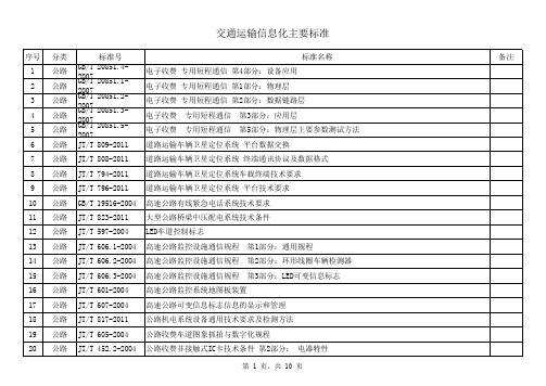
交通运输信息化主要标准
序号 60 61 62 63 64 65 66 67 68 69 70 71 72 73 74 75 76 77 78 79 分类 公路 公路 公路 公路 公路 公路 公路 公路 公路 公路 公路 公路 公路 公路 公路 公路 公路 公路 公路 公路 标准号 GB/T 20606-2006 GB/T 20607-2006 GB/T 20611-2006 GB/T 20608-2006 GB/T 26764-2011 JT/T 703-2007 JT/T 621-2005 GB/T 7262-2009 JT/T 228-2008 JT/T 452.1-2001 GB 23826-2009 GB/T 23828-2009 GB/T 20135-2006 JT/T 715-2008 JT/T 714-2008 GB/T 20609-2006 GB/T 26771-2011 GB/T 18567-2010 GB/T 26773-2011 JT/T 789-2010 智能运输系统 数据字典要求 智能运输系统 体系结构 服务 智能运输系统 中央数据登记簿 数据管理机制要求 智能运输系统 自适应巡航控制系统 性能要求与检测方法 多功能路况快速检测设备 高速公路紧急电话系统 公路GSM/CDMA数字紧急电话系统 公路通信技术要求及设备配备 交通小型无线电基地台接地和防雷技术要求 公路收费非接触式IC卡 第1部分:物理特性 高速公路LED可变限速标志 高速公路LED可变信息标志 智能运输系统 电子收费系统框架模型 道路交通气象环境 埋入式路面状况检测器 道路交通气象环境 能见度检测器 交通信息采集 微波交通流检测器 微波交通流检测器的设置 高速公路隧道监控系统模式 智能运输系统 车道偏离报警系统 性能要求与检测方法 道路甩挂运输车辆技术条件
极限交换机VDX6740和VDX6740T产品介绍说明书
The VDX 674 0 T-1G ( Fig ure 3) offers 4 8 10 0 0 BA SE-T p ort s and t w o 4 0 Gb E QSFP+ p ort s. Each 4 0 Gb E p ort can b e b roken out int o four ind ep end ent 10 Gb E SFP+ p ort s, p rovid ing an ad d it ional eig ht 10 Gb E SFP+ p ort s for up link. A ll 4 8 10 0 0 BA SE-T p ort s can b e up g rad ed t o 4 8 10 GBA SE-T p ort s via t he Cap acit y on Dem and (CoD) soft w are license. Tw o 4 0 Gb E p ort s are enab led as p art of t he b ase license. The ad d it ional t w o 4 0 Gb E p ort s can b e up g rad ed via t he Port s on Dem and ( PoD) soft w are license.
- Meet s t od ay?s ap p licat ion d em and s w it h high perform ance and low latency
- Delivers line-rate t hroughput for all p ort s and p acket sizes
Dat a Sheet
中国商用车发动机CAN通讯规范
SRR-代用远程请求 SA# - SAE J1939目标地址#n
RTR-远程传输请求位 DP-SAE J1939数据页
IDE-标识符扩展位 PF# - SAE J1939 PDU格式位#n
r # - CAN保留位 PS# - SAE J1939 特定PDU位#n
DLC# - 数据长度码位#n
(d)- 显性位
EEC
Electronic Engine Controller
转速表
TCO
Tachograph
车辆智能中心
VIC
Vehicle Intelligence Centre
排气缓速器
XR
Exhaust Retarder
高字节
MSB
Most Significant Byte
低字节
LSB
Least Significant Byte
参数组编号(PGN)
在CAN数据帧的数据域中需要指明参数组时,PGN是表示成24位。PGN是一个24位的值,包括以下要素:保留位、数据页位、PDU格式域(8位)和群扩展域(8位)。各个位转化到PGN的过程如下。若PF值小于240(F016),PGN的低字节置0。注意:用本文档规定的范例,并非全部131,071种组合都可用于分配(计算如下:2页*[240+(16*256)]=8,670)。见SAE J1939附录A,可查现行的最新分配。参见PGN表,表6,位和其相应的十进制转化。
CCIE Security V4 350-018 (带部分中文注释)
CCIE SECURITY V4.0 350-018186Q注:本文全部为个人手打,目的是为了方便记忆。
中文注释为个人翻译,不一定正确,仅供参考!1,which two EIGRP packet tpes are considered to be unreliable packets?(那俩类型的EIGRP 包的是不可靠的包)A,updateB,queryC,replyD,helloE,acknowledgement(明显hello不一定有人回所以不会需要确认,ack为确认包也不再一直确认)2,before BGP update messages may be sent,a neighbor must stabilize into which neighbor state?(BGP的邻居必须稳定在那种状态时可能会发送更新包)A,activeB, idleC,connectedD,established(established状态为BGP对等体建立完成,这时才可以交换update)3,which three statements are cortect when comparing mobile IPv6 and mobile IPv4 support?(那三句话正确的对比了移动IPV6 和移动IPV4)A,mobile ipv6 does not require a foreign agent,but mobile ipv4 doesB,mobile ipv6 supports route optimization as a fundamental part of the protocol;ipv4 requires extensionsC,mobile ipv6 and mobile ipv4 use a directed broadcast approach for home agent address discoveryD,mobile ipv6 makes ues of its own routing header, mobile ipv4 uses only ip encapsulationE,mobile ipv6 and mobile ipv4 use arp for neighbor discoveryF,mobile ipv4 has adopted the use of ipv6 ND(v6不需要外地代理v4需要, 路由优化是v6基本协议的一部分,v4在扩展协议里,v6有自己的路由头v4只有ip封装)4,which protocol does 802.1x use between the supplicant and the authenticator to authenticate users wish to access the network?(在802.1x的请求者和认证者间认证协议是那个)A,snmpB,tacacs+C,radiusD,eap over lanE,pppoe(802.1x主要用于请求者和认证者间封装EAP的二层协议,简称EAPOL)5,refer to the exhibit. Which message could contain an authenticated initial_contact notifyduring IKE main mode negotiation?(参考下图,那条信息包含IKE主模式认证初始接触通知)A,message3B,message5C,message1D,none,initial_contact is sent only during quick modeE,none,notify messages are sent only as independent message types(1、2个包为认证和加密模式交换,3、4为DH交换,第5个包开始是认证信息) 6,which two statements are correct regarding the AES encryption algorithm?(关于AES加密下面那两个说法正确)A,it is a FIPS-approved symmetric block cipherB,it supports a block size of 128,192or 256 bitsC,it supports a variable length block size from 16 to 448 bitsD, it supports a cipher key size of 128,192or256 bitsE,the AES encryption algorithm is based on the presumed difficulty of factoring large integers(AES是FIPS认可的一个块加密的对称密钥算法,块大小为128位,密钥大小可以为128、192或256)7,what are two benefits of using IKEv2 instead of IKEv1 when deploying remot-access IPsec VPN?(用IKEV2代替IKEV1部署远程访问IPSECVPN的两个好处是什么)A,IKEv2 supports EAP authentication methods as part of the protocolB, IKEv2 inherently supports NAT traversalC,IKEv2 messages use random message IDsD,the IKEv2 SA plus the IPsec SA can be established in six messages instead of nine messagesE,all IKEv2 messages are encryption-protected(EAP和NAT-T是IKEv2的标准组件,对于远程访问是对较方便的)8,DNSSEC was designed to overcome which security limitation of DNS? (DNSSEC是被设计用于克服那种安全攻击的)A,DNS man-in-the-middle attacksB,DNS flood attacksC,DNS fragmentation attacksD,DNS hash attacksE,DNS replay attacksF,DNS violation attacks(DNSSEC提供了源验证和数据完整性校验,可以有效的抵御中间人攻击)9,which three statements true about MAC sec?(关于MACsec那三个描述是正确的)A,it supports GCM modes of AES and 3DESB,it is defined under IEEE 802.1AEC,it provides hop-by-hop encryption at layer 2D,MACsec expects a strict order of frames to prevent anti-replayE,MKA is used for session and encryption key managementF,it uses EAP PACs to distribute encryption keys(MACsec是遵循dot1ae的二层加密协议,加密点到点的数据,也就是说加密流量不会穿越二层设备,使用MKA协商和管理密钥)10,which SSL protocol takes an application message to be transmitted,fragments the data into manageable blocks, optionally compresses the data,applies a MAC,encrypts,adds a header,and transmits the resulting unit in a TCP segment?A,SSL handshake protocolB,SSL alert protocolC,SSL record protocolD,SSL change cipherspec protocol(SSL协议可分为两层:SSL记录协议(SSL Record Protocol):它建立在可靠的传输协议(如TCP)之上,为高层协议提供数据封装、压缩、加密等基本功能的支持。
rfc7348
Independent Submission M. Mahalingam Request for Comments: 7348 Storvisor Category: Informational D. Dutt ISSN: 2070-1721 Cumulus Networks K. Duda Arista P. Agarwal Broadcom L. Kreeger Cisco T. Sridhar VMware M. Bursell Intel C. Wright Red Hat August 2014 Virtual eXtensible Local Area Network (VXLAN): A Frameworkfor Overlaying Virtualized Layer 2 Networks over Layer 3 Networks AbstractThis document describes Virtual eXtensible Local Area Network(VXLAN), which is used to address the need for overlay networkswithin virtualized data centers accommodating multiple tenants. The scheme and the related protocols can be used in networks for cloudservice providers and enterprise data centers. This memo documentsthe deployed VXLAN protocol for the benefit of the Internetcommunity.Status of This MemoThis document is not an Internet Standards Track specification; it is published for informational purposes.This is a contribution to the RFC Series, independently of any other RFC stream. The RFC Editor has chosen to publish this document atits discretion and makes no statement about its value forimplementation or deployment. Documents approved for publication by the RFC Editor are not a candidate for any level of InternetStandard; see Section 2 of RFC 5741.Information about the current status of this document, any errata,and how to provide feedback on it may be obtained at/info/rfc7348.Mahalingam, et al. Informational [Page 1]Copyright NoticeCopyright (c) 2014 IETF Trust and the persons identified as thedocument authors. All rights reserved.This document is subject to BCP 78 and the IETF Trust’s LegalProvisions Relating to IETF Documents(/license-info) in effect on the date ofpublication of this document. Please review these documentscarefully, as they describe your rights and restrictions with respect to this document.Table of Contents1. Introduction (3)1.1. Acronyms and Definitions (4)2. Conventions Used in This Document (4)3. VXLAN Problem Statement (5)3.1. Limitations Imposed by Spanning Tree and VLAN Ranges (5)3.2. Multi-tenant Environments (5)3.3. Inadequate Table Sizes at ToR Switch (6)4. VXLAN (6)4.1. Unicast VM-to-VM Communication (7)4.2. Broadcast Communication and Mapping to Multicast (8)4.3. Physical Infrastructure Requirements (9)5. VXLAN Frame Format (10)6. VXLAN Deployment Scenarios (14)6.1. Inner VLAN Tag Handling (18)7. Security Considerations (18)8. IANA Considerations (19)9. References (19)9.1. Normative References (19)9.2. Informative References (20)10. Acknowledgments (21)Mahalingam, et al. Informational [Page 2]1. IntroductionServer virtualization has placed increased demands on the physicalnetwork infrastructure. A physical server now has multiple VirtualMachines (VMs) each with its own Media Access Control (MAC) address. This requires larger MAC address tables in the switched Ethernetnetwork due to potential attachment of and communication amonghundreds of thousands of VMs.In the case when the VMs in a data center are grouped according totheir Virtual LAN (VLAN), one might need thousands of VLANs topartition the traffic according to the specific group to which the VM may belong. The current VLAN limit of 4094 is inadequate in suchsituations.Data centers are often required to host multiple tenants, each withtheir own isolated network domain. Since it is not economical torealize this with dedicated infrastructure, network administratorsopt to implement isolation over a shared network. In such scenarios, a common problem is that each tenant may independently assign MACaddresses and VLAN IDs leading to potential duplication of these onthe physical network.An important requirement for virtualized environments using a Layer 2 physical infrastructure is having the Layer 2 network scale acrossthe entire data center or even between data centers for efficientallocation of compute, network, and storage resources. In suchnetworks, using traditional approaches like the Spanning TreeProtocol (STP) for a loop-free topology can result in a large number of disabled links.The last scenario is the case where the network operator prefers touse IP for interconnection of the physical infrastructure (e.g., toachieve multipath scalability through Equal-Cost Multipath (ECMP),thus avoiding disabled links). Even in such environments, there is a need to preserve the Layer 2 model for inter-VM communication.The scenarios described above lead to a requirement for an overlaynetwork. This overlay is used to carry the MAC traffic from theindividual VMs in an encapsulated format over a logical "tunnel".This document details a framework termed "Virtual eXtensible LocalArea Network (VXLAN)" that provides such an encapsulation scheme toaddress the various requirements specified above. This memodocuments the deployed VXLAN protocol for the benefit of the Internet community.Mahalingam, et al. Informational [Page 3]1.1. Acronyms and DefinitionsACL Access Control ListECMP Equal-Cost MultipathIGMP Internet Group Management ProtocolIHL Internet Header LengthMTU Maximum Transmission UnitPIM Protocol Independent MulticastSPB Shortest Path BridgingSTP Spanning Tree ProtocolToR Top of RackTRILL Transparent Interconnection of Lots of LinksVLAN Virtual Local Area NetworkVM Virtual MachineVNI VXLAN Network Identifier (or VXLAN Segment ID)VTEP VXLAN Tunnel End Point. An entity that originates and/orterminates VXLAN tunnelsVXLAN Virtual eXtensible Local Area NetworkVXLAN SegmentVXLAN Layer 2 overlay network over which VMs communicateVXLAN Gatewayan entity that forwards traffic between VXLANs2. Conventions Used in This DocumentThe key words "MUST", "MUST NOT", "REQUIRED", "SHALL", "SHALL NOT","SHOULD", "SHOULD NOT", "RECOMMENDED", "MAY", and "OPTIONAL" in this document are to be interpreted as described in RFC 2119 [RFC2119]. Mahalingam, et al. Informational [Page 4]3. VXLAN Problem StatementThis section provides further details on the areas that VXLAN isintended to address. The focus is on the networking infrastructurewithin the data center and the issues related to them.3.1. Limitations Imposed by Spanning Tree and VLAN RangesCurrent Layer 2 networks use the IEEE 802.1D Spanning Tree Protocol(STP) [802.1D] to avoid loops in the network due to duplicate paths. STP blocks the use of links to avoid the replication and looping offrames. Some data center operators see this as a problem with Layer 2 networks in general, since with STP they are effectively paying for more ports and links than they can really use. In addition,resiliency due to multipathing is not available with the STP model.Newer initiatives, such as TRILL [RFC6325] and SPB [802.1aq], havebeen proposed to help with multipathing and surmount some of theproblems with STP. STP limitations may also be avoided byconfiguring servers within a rack to be on the same Layer 3 network, with switching happening at Layer 3 both within the rack and between racks. However, this is incompatible with a Layer 2 model for inter- VM communication.A key characteristic of Layer 2 data center networks is their use of Virtual LANs (VLANs) to provide broadcast isolation. A 12-bit VLANID is used in the Ethernet data frames to divide the larger Layer 2network into multiple broadcast domains. This has served well formany data centers that require fewer than 4094 VLANs. With thegrowing adoption of virtualization, this upper limit is seeingpressure. Moreover, due to STP, several data centers limit thenumber of VLANs that could be used. In addition, requirements formulti-tenant environments accelerate the need for larger VLAN limits, as discussed in Section 3.3.3.2. Multi-tenant EnvironmentsCloud computing involves on-demand elastic provisioning of resources for multi-tenant environments. The most common example of cloudcomputing is the public cloud, where a cloud service provider offers these elastic services to multiple customers/tenants over the samephysical infrastructure.Isolation of network traffic by a tenant could be done via Layer 2 or Layer 3 networks. For Layer 2 networks, VLANs are often used tosegregate traffic -- so a tenant could be identified by its own VLAN, for example. Due to the large number of tenants that a cloud Mahalingam, et al. Informational [Page 5]provider might service, the 4094 VLAN limit is often inadequate. In addition, there is often a need for multiple VLANs per tenant, which exacerbates the issue.A related use case is cross-pod expansion. A pod typically consists of one or more racks of servers with associated network and storageconnectivity. Tenants may start off on a pod and, due to expansion, require servers/VMs on other pods, especially in the case whentenants on the other pods are not fully utilizing all theirresources. This use case requires a "stretched" Layer 2 environment connecting the individual servers/VMs.Layer 3 networks are not a comprehensive solution for multi-tenancyeither. Two tenants might use the same set of Layer 3 addresseswithin their networks, which requires the cloud provider to provideisolation in some other form. Further, requiring all tenants to use IP excludes customers relying on direct Layer 2 or non-IP Layer 3protocols for inter VM communication.3.3. Inadequate Table Sizes at ToR SwitchToday’s virtualized environments place additional demands on the MAC address tables of Top-of-Rack (ToR) switches that connect to theservers. Instead of just one MAC address per server link, the ToRnow has to learn the MAC addresses of the individual VMs (which could range in the hundreds per server). This is needed because trafficto/from the VMs to the rest of the physical network will traverse the link between the server and the switch. A typical ToR switch couldconnect to 24 or 48 servers depending upon the number of its server- facing ports. A data center might consist of several racks, so each ToR switch would need to maintain an address table for thecommunicating VMs across the various physical servers. This places a much larger demand on the table capacity compared to non-virtualized environments.If the table overflows, the switch may stop learning new addressesuntil idle entries age out, leading to significant flooding ofsubsequent unknown destination frames.4. VXLANVXLAN (Virtual eXtensible Local Area Network) addresses the aboverequirements of the Layer 2 and Layer 3 data center networkinfrastructure in the presence of VMs in a multi-tenant environment. It runs over the existing networking infrastructure and provides ameans to "stretch" a Layer 2 network. In short, VXLAN is a Layer 2overlay scheme on a Layer 3 network. Each overlay is termed a VXLAN segment. Only VMs within the same VXLAN segment can communicate with Mahalingam, et al. Informational [Page 6]each other. Each VXLAN segment is identified through a 24-bitsegment ID, termed the "VXLAN Network Identifier (VNI)". This allows up to 16 M VXLAN segments to coexist within the same administrativedomain.The VNI identifies the scope of the inner MAC frame originated by the individual VM. Thus, you could have overlapping MAC addresses across segments but never have traffic "cross over" since the traffic isisolated using the VNI. The VNI is in an outer header thatencapsulates the inner MAC frame originated by the VM. In thefollowing sections, the term "VXLAN segment" is used interchangeably with the term "VXLAN overlay network".Due to this encapsulation, VXLAN could also be called a tunnelingscheme to overlay Layer 2 networks on top of Layer 3 networks. Thetunnels are stateless, so each frame is encapsulated according to aset of rules. The end point of the tunnel (VXLAN Tunnel End Point or VTEP) discussed in the following sections is located within thehypervisor on the server that hosts the VM. Thus, the VNI- andVXLAN-related tunnel / outer header encapsulation are known only tothe VTEP -- the VM never sees it (see Figure 1). Note that it ispossible that VTEPs could also be on a physical switch or physicalserver and could be implemented in software or hardware. One usecase where the VTEP is a physical switch is discussed in Section 6 on VXLAN deployment scenarios.The following sections discuss typical traffic flow scenarios in aVXLAN environment using one type of control scheme -- data planelearning. Here, the association of VM’s MAC to VTEP’s IP address is discovered via source-address learning. Multicast is used forcarrying unknown destination, broadcast, and multicast frames.In addition to a learning-based control plane, there are otherschemes possible for the distribution of the VTEP IP to VM MACmapping information. Options could include a centralauthority-/directory-based lookup by the individual VTEPs,distribution of this mapping information to the VTEPs by the central authority, and so on. These are sometimes characterized as push and pull models, respectively. This document will focus on the dataplane learning scheme as the control plane for VXLAN.4.1. Unicast VM-to-VM CommunicationConsider a VM within a VXLAN overlay network. This VM is unaware of VXLAN. To communicate with a VM on a different host, it sends a MAC frame destined to the target as normal. The VTEP on the physicalhost looks up the VNI to which this VM is associated. It thendetermines if the destination MAC is on the same segment and if there Mahalingam, et al. Informational [Page 7]is a mapping of the destination MAC address to the remote VTEP. Ifso, an outer header comprising an outer MAC, outer IP header, andVXLAN header (see Figure 1 in Section 5 for frame format) areprepended to the original MAC frame. The encapsulated packet isforwarded towards the remote VTEP. Upon reception, the remote VTEPverifies the validity of the VNI and whether or not there is a VM on that VNI using a MAC address that matches the inner destination MACaddress. If so, the packet is stripped of its encapsulating headers and passed on to the destination VM. The destination VM never knows about the VNI or that the frame was transported with a VXLANencapsulation.In addition to forwarding the packet to the destination VM, theremote VTEP learns the mapping from inner source MAC to outer source IP address. It stores this mapping in a table so that when thedestination VM sends a response packet, there is no need for an"unknown destination" flooding of the response packet.Determining the MAC address of the destination VM prior to thetransmission by the source VM is performed as with non-VXLANenvironments except as described in Section 4.2. Broadcast framesare used but are encapsulated within a multicast packet, as detailed in the Section 4.2.4.2. Broadcast Communication and Mapping to MulticastConsider the VM on the source host attempting to communicate with the destination VM using IP. Assuming that they are both on the samesubnet, the VM sends out an Address Resolution Protocol (ARP)broadcast frame. In the non-VXLAN environment, this frame would besent out using MAC broadcast across all switches carrying that VLAN. With VXLAN, a header including the VXLAN VNI is inserted at thebeginning of the packet along with the IP header and UDP header.However, this broadcast packet is sent out to the IP multicast group on which that VXLAN overlay network is realized.To effect this, we need to have a mapping between the VXLAN VNI andthe IP multicast group that it will use. This mapping is done at the management layer and provided to the individual VTEPs through amanagement channel. Using this mapping, the VTEP can provide IGMPmembership reports to the upstream switch/router to join/leave theVXLAN-related IP multicast groups as needed. This will enablepruning of the leaf nodes for specific multicast traffic addressesbased on whether a member is available on this host using thespecific multicast address (see [RFC4541]). In addition, use of Mahalingam, et al. Informational [Page 8]multicast routing protocols like Protocol Independent Multicast -Sparse Mode (PIM-SM see [RFC4601]) will provide efficient multicasttrees within the Layer 3 network.The VTEP will use (*,G) joins. This is needed as the set of VXLANtunnel sources is unknown and may change often, as the VMs come up / go down across different hosts. A side note here is that since each VTEP can act as both the source and destination for multicastpackets, a protocol like bidirectional PIM (BIDIR-PIM -- see[RFC5015]) would be more efficient.The destination VM sends a standard ARP response using IP unicast.This frame will be encapsulated back to the VTEP connecting theoriginating VM using IP unicast VXLAN encapsulation. This ispossible since the mapping of the ARP response’s destination MAC tothe VXLAN tunnel end point IP was learned earlier through the ARPrequest.Note that multicast frames and "unknown MAC destination" frames arealso sent using the multicast tree, similar to the broadcast frames.4.3. Physical Infrastructure RequirementsWhen IP multicast is used within the network infrastructure, amulticast routing protocol like PIM-SM can be used by the individual Layer 3 IP routers/switches within the network. This is used tobuild efficient multicast forwarding trees so that multicast framesare only sent to those hosts that have requested to receive them.Similarly, there is no requirement that the actual network connecting the source VM and destination VM should be a Layer 3 network: VXLANcan also work over Layer 2 networks. In either case, efficientmulticast replication within the Layer 2 network can be achievedusing IGMP snooping.VTEPs MUST NOT fragment VXLAN packets. Intermediate routers mayfragment encapsulated VXLAN packets due to the larger frame size.The destination VTEP MAY silently discard such VXLAN fragments. Toensure end-to-end traffic delivery without fragmentation, it isRECOMMENDED that the MTUs (Maximum Transmission Units) across thephysical network infrastructure be set to a value that accommodatesthe larger frame size due to the encapsulation. Other techniqueslike Path MTU discovery (see [RFC1191] and [RFC1981]) MAY be used to address this requirement as well.Mahalingam, et al. Informational [Page 9]5. VXLAN Frame FormatThe VXLAN frame format is shown below. Parsing this from the bottom of the frame -- above the outer Frame Check Sequence (FCS), there is an inner MAC frame with its own Ethernet header with source,destination MAC addresses along with the Ethernet type, plus anoptional VLAN. See Section 6 for further details of inner VLAN taghandling.The inner MAC frame is encapsulated with the following four headers(starting from the innermost header):VXLAN Header: This is an 8-byte field that has:- Flags (8 bits): where the I flag MUST be set to 1 for a validVXLAN Network ID (VNI). The other 7 bits (designated "R") arereserved fields and MUST be set to zero on transmission andignored on receipt.- VXLAN Segment ID/VXLAN Network Identifier (VNI): this is a24-bit value used to designate the individual VXLAN overlaynetwork on which the communicating VMs are situated. VMs indifferent VXLAN overlay networks cannot communicate with eachother.- Reserved fields (24 bits and 8 bits): MUST be set to zero ontransmission and ignored on receipt.Outer UDP Header: This is the outer UDP header with a source portprovided by the VTEP and the destination port being a well-knownUDP port.- Destination Port: IANA has assigned the value 4789 for theVXLAN UDP port, and this value SHOULD be used by default as the destination UDP port. Some early implementations of VXLAN have used other values for the destination port. To enableinteroperability with these implementations, the destinationport SHOULD be configurable.- Source Port: It is recommended that the UDP source port number be calculated using a hash of fields from the inner packet --one example being a hash of the inner Ethernet frame’s headers. This is to enable a level of entropy for the ECMP/load-balancing of the VM-to-VM traffic across the VXLAN overlay.When calculating the UDP source port number in this manner, it is RECOMMENDED that the value be in the dynamic/private portrange 49152-65535 [RFC6335].Mahalingam, et al. Informational [Page 10]- UDP Checksum: It SHOULD be transmitted as zero. When a packet is received with a UDP checksum of zero, it MUST be acceptedfor decapsulation. Optionally, if the encapsulating end point includes a non-zero UDP checksum, it MUST be correctlycalculated across the entire packet including the IP header,UDP header, VXLAN header, and encapsulated MAC frame. When adecapsulating end point receives a packet with a non-zerochecksum, it MAY choose to verify the checksum value. If itchooses to perform such verification, and the verificationfails, the packet MUST be dropped. If the decapsulatingdestination chooses not to perform the verification, orperforms it successfully, the packet MUST be accepted fordecapsulation.Outer IP Header: This is the outer IP header with the source IPaddress indicating the IP address of the VTEP over which thecommunicating VM (as represented by the inner source MAC address) is running. The destination IP address can be a unicast ormulticast IP address (see Sections 4.1 and 4.2). When it is aunicast IP address, it represents the IP address of the VTEPconnecting the communicating VM as represented by the innerdestination MAC address. For multicast destination IP addresses, please refer to the scenarios detailed in Section 4.2.Outer Ethernet Header (example): Figure 1 is an example of an inner Ethernet frame encapsulated within an outer Ethernet + IP + UDP + VXLAN header. The outer destination MAC address in this frame may be the address of the target VTEP or of an intermediate Layer 3router. The outer VLAN tag is optional. If present, it may beused for delineating VXLAN traffic on the LAN.0 1 2 30 1 2 3 4 5 6 7 8 9 0 1 2 3 4 5 6 7 8 9 0 1 2 3 4 5 6 7 8 9 0 1Outer Ethernet Header:+-+-+-+-+-+-+-+-+-+-+-+-+-+-+-+-+-+-+-+-+-+-+-+-+-+-+-+-+-+-+-+-+| Outer Destination MAC Address |+-+-+-+-+-+-+-+-+-+-+-+-+-+-+-+-+-+-+-+-+-+-+-+-+-+-+-+-+-+-+-+-+| Outer Destination MAC Address | Outer Source MAC Address |+-+-+-+-+-+-+-+-+-+-+-+-+-+-+-+-+-+-+-+-+-+-+-+-+-+-+-+-+-+-+-+-+| Outer Source MAC Address |+-+-+-+-+-+-+-+-+-+-+-+-+-+-+-+-+-+-+-+-+-+-+-+-+-+-+-+-+-+-+-+-+|OptnlEthtype = C-Tag 802.1Q | Outer.VLAN Tag Information |+-+-+-+-+-+-+-+-+-+-+-+-+-+-+-+-+-+-+-+-+-+-+-+-+-+-+-+-+-+-+-+-+| Ethertype = 0x0800 |+-+-+-+-+-+-+-+-+-+-+-+-+-+-+-+-+Mahalingam, et al. Informational [Page 11]Outer IPv4 Header:+-+-+-+-+-+-+-+-+-+-+-+-+-+-+-+-+-+-+-+-+-+-+-+-+-+-+-+-+-+-+-+-+|Version| IHL |Type of Service| Total Length |+-+-+-+-+-+-+-+-+-+-+-+-+-+-+-+-+-+-+-+-+-+-+-+-+-+-+-+-+-+-+-+-+| Identification |Flags| Fragment Offset |+-+-+-+-+-+-+-+-+-+-+-+-+-+-+-+-+-+-+-+-+-+-+-+-+-+-+-+-+-+-+-+-+| Time to Live |Protocl=17(UDP)| Header Checksum |+-+-+-+-+-+-+-+-+-+-+-+-+-+-+-+-+-+-+-+-+-+-+-+-+-+-+-+-+-+-+-+-+| Outer Source IPv4 Address |+-+-+-+-+-+-+-+-+-+-+-+-+-+-+-+-+-+-+-+-+-+-+-+-+-+-+-+-+-+-+-+-+| Outer Destination IPv4 Address |+-+-+-+-+-+-+-+-+-+-+-+-+-+-+-+-+-+-+-+-+-+-+-+-+-+-+-+-+-+-+-+-+Outer UDP Header:+-+-+-+-+-+-+-+-+-+-+-+-+-+-+-+-+-+-+-+-+-+-+-+-+-+-+-+-+-+-+-+-+| Source Port | Dest Port = VXLAN Port |+-+-+-+-+-+-+-+-+-+-+-+-+-+-+-+-+-+-+-+-+-+-+-+-+-+-+-+-+-+-+-+-+| UDP Length | UDP Checksum |+-+-+-+-+-+-+-+-+-+-+-+-+-+-+-+-+-+-+-+-+-+-+-+-+-+-+-+-+-+-+-+-+VXLAN Header:+-+-+-+-+-+-+-+-+-+-+-+-+-+-+-+-+-+-+-+-+-+-+-+-+-+-+-+-+-+-+-+-+|R|R|R|R|I|R|R|R| Reserved |+-+-+-+-+-+-+-+-+-+-+-+-+-+-+-+-+-+-+-+-+-+-+-+-+-+-+-+-+-+-+-+-+| VXLAN Network Identifier (VNI) | Reserved |+-+-+-+-+-+-+-+-+-+-+-+-+-+-+-+-+-+-+-+-+-+-+-+-+-+-+-+-+-+-+-+-+Inner Ethernet Header:+-+-+-+-+-+-+-+-+-+-+-+-+-+-+-+-+-+-+-+-+-+-+-+-+-+-+-+-+-+-+-+-+| Inner Destination MAC Address |+-+-+-+-+-+-+-+-+-+-+-+-+-+-+-+-+-+-+-+-+-+-+-+-+-+-+-+-+-+-+-+-+| Inner Destination MAC Address | Inner Source MAC Address |+-+-+-+-+-+-+-+-+-+-+-+-+-+-+-+-+-+-+-+-+-+-+-+-+-+-+-+-+-+-+-+-+| Inner Source MAC Address |+-+-+-+-+-+-+-+-+-+-+-+-+-+-+-+-+-+-+-+-+-+-+-+-+-+-+-+-+-+-+-+-+|OptnlEthtype = C-Tag 802.1Q | Inner.VLAN Tag Information |+-+-+-+-+-+-+-+-+-+-+-+-+-+-+-+-+-+-+-+-+-+-+-+-+-+-+-+-+-+-+-+-+Payload:+-+-+-+-+-+-+-+-+-+-+-+-+-+-+-+-+-+-+-+-+-+-+-+-+-+-+-+-+-+-+-+-+| Ethertype of Original Payload | |+-+-+-+-+-+-+-+-+-+-+-+-+-+-+-+-+ || Original Ethernet Payload || ||(Note that the original Ethernet Frame’s FCS is not included) |+-+-+-+-+-+-+-+-+-+-+-+-+-+-+-+-+-+-+-+-+-+-+-+-+-+-+-+-+-+-+-+-+ Mahalingam, et al. Informational [Page 12]Frame Check Sequence:+-+-+-+-+-+-+-+-+-+-+-+-+-+-+-+-+-+-+-+-+-+-+-+-+-+-+-+-+-+-+-+-+| New FCS (Frame Check Sequence) for Outer Ethernet Frame |+-+-+-+-+-+-+-+-+-+-+-+-+-+-+-+-+-+-+-+-+-+-+-+-+-+-+-+-+-+-+-+-+Figure 1: VXLAN Frame Format with IPv4 Outer HeaderThe frame format above shows tunneling of Ethernet frames using IPv4 for transport. Use of VXLAN with IPv6 transport is detailed below.0 1 2 30 1 2 3 4 5 6 7 8 9 0 1 2 3 4 5 6 7 8 9 0 1 2 3 4 5 6 7 8 9 0 1Outer Ethernet Header:+-+-+-+-+-+-+-+-+-+-+-+-+-+-+-+-+-+-+-+-+-+-+-+-+-+-+-+-+-+-+-+-+| Outer Destination MAC Address |+-+-+-+-+-+-+-+-+-+-+-+-+-+-+-+-+-+-+-+-+-+-+-+-+-+-+-+-+-+-+-+-+| Outer Destination MAC Address | Outer Source MAC Address |+-+-+-+-+-+-+-+-+-+-+-+-+-+-+-+-+-+-+-+-+-+-+-+-+-+-+-+-+-+-+-+-+| Outer Source MAC Address |+-+-+-+-+-+-+-+-+-+-+-+-+-+-+-+-+-+-+-+-+-+-+-+-+-+-+-+-+-+-+-+-+|OptnlEthtype = C-Tag 802.1Q | Outer.VLAN Tag Information |+-+-+-+-+-+-+-+-+-+-+-+-+-+-+-+-+-+-+-+-+-+-+-+-+-+-+-+-+-+-+-+-+| Ethertype = 0x86DD |+-+-+-+-+-+-+-+-+-+-+-+-+-+-+-+-+Outer IPv6 Header:+-+-+-+-+-+-+-+-+-+-+-+-+-+-+-+-+-+-+-+-+-+-+-+-+-+-+-+-+-+-+-+-+|Version| Traffic Class | Flow Label |+-+-+-+-+-+-+-+-+-+-+-+-+-+-+-+-+-+-+-+-+-+-+-+-+-+-+-+-+-+-+-+-+| Payload Length | NxtHdr=17(UDP)| Hop Limit |+-+-+-+-+-+-+-+-+-+-+-+-+-+-+-+-+-+-+-+-+-+-+-+-+-+-+-+-+-+-+-+-+| |+ +| |+ Outer Source IPv6 Address +| |+ +| |+-+-+-+-+-+-+-+-+-+-+-+-+-+-+-+-+-+-+-+-+-+-+-+-+-+-+-+-+-+-+-+-+| |+ +| |+ Outer Destination IPv6 Address +| |+ +| |+-+-+-+-+-+-+-+-+-+-+-+-+-+-+-+-+-+-+-+-+-+-+-+-+-+-+-+-+-+-+-+-+ Mahalingam, et al. Informational [Page 13]Outer UDP Header:+-+-+-+-+-+-+-+-+-+-+-+-+-+-+-+-+-+-+-+-+-+-+-+-+-+-+-+-+-+-+-+-+| Source Port | Dest Port = VXLAN Port |+-+-+-+-+-+-+-+-+-+-+-+-+-+-+-+-+-+-+-+-+-+-+-+-+-+-+-+-+-+-+-+-+| UDP Length | UDP Checksum |+-+-+-+-+-+-+-+-+-+-+-+-+-+-+-+-+-+-+-+-+-+-+-+-+-+-+-+-+-+-+-+-+VXLAN Header:+-+-+-+-+-+-+-+-+-+-+-+-+-+-+-+-+-+-+-+-+-+-+-+-+-+-+-+-+-+-+-+-+|R|R|R|R|I|R|R|R| Reserved |+-+-+-+-+-+-+-+-+-+-+-+-+-+-+-+-+-+-+-+-+-+-+-+-+-+-+-+-+-+-+-+-+| VXLAN Network Identifier (VNI) | Reserved |+-+-+-+-+-+-+-+-+-+-+-+-+-+-+-+-+-+-+-+-+-+-+-+-+-+-+-+-+-+-+-+-+Inner Ethernet Header:+-+-+-+-+-+-+-+-+-+-+-+-+-+-+-+-+-+-+-+-+-+-+-+-+-+-+-+-+-+-+-+-+| Inner Destination MAC Address |+-+-+-+-+-+-+-+-+-+-+-+-+-+-+-+-+-+-+-+-+-+-+-+-+-+-+-+-+-+-+-+-+| Inner Destination MAC Address | Inner Source MAC Address |+-+-+-+-+-+-+-+-+-+-+-+-+-+-+-+-+-+-+-+-+-+-+-+-+-+-+-+-+-+-+-+-+| Inner Source MAC Address |+-+-+-+-+-+-+-+-+-+-+-+-+-+-+-+-+-+-+-+-+-+-+-+-+-+-+-+-+-+-+-+-+|OptnlEthtype = C-Tag 802.1Q | Inner.VLAN Tag Information |+-+-+-+-+-+-+-+-+-+-+-+-+-+-+-+-+-+-+-+-+-+-+-+-+-+-+-+-+-+-+-+-+Payload:+-+-+-+-+-+-+-+-+-+-+-+-+-+-+-+-+-+-+-+-+-+-+-+-+-+-+-+-+-+-+-+-+| Ethertype of Original Payload | |+-+-+-+-+-+-+-+-+-+-+-+-+-+-+-+-+ || Original Ethernet Payload || ||(Note that the original Ethernet Frame’s FCS is not included) |+-+-+-+-+-+-+-+-+-+-+-+-+-+-+-+-+-+-+-+-+-+-+-+-+-+-+-+-+-+-+-+-+Frame Check Sequence:+-+-+-+-+-+-+-+-+-+-+-+-+-+-+-+-+-+-+-+-+-+-+-+-+-+-+-+-+-+-+-+-+| New FCS (Frame Check Sequence) for Outer Ethernet Frame |+-+-+-+-+-+-+-+-+-+-+-+-+-+-+-+-+-+-+-+-+-+-+-+-+-+-+-+-+-+-+-+-+Figure 2: VXLAN Frame Format with IPv6 Outer Header6. VXLAN Deployment ScenariosVXLAN is typically deployed in data centers on virtualized hosts,which may be spread across multiple racks. The individual racks may be parts of a different Layer 3 network or they could be in a single Layer 2 network. The VXLAN segments/overlay networks are overlaid on top of these Layer 2 or Layer 3 networks.Mahalingam, et al. Informational [Page 14]。
- 1、下载文档前请自行甄别文档内容的完整性,平台不提供额外的编辑、内容补充、找答案等附加服务。
- 2、"仅部分预览"的文档,不可在线预览部分如存在完整性等问题,可反馈申请退款(可完整预览的文档不适用该条件!)。
- 3、如文档侵犯您的权益,请联系客服反馈,我们会尽快为您处理(人工客服工作时间:9:00-18:30)。
Network Working Group E. Bell Request for Comments: 2674 3Com Corp. Category: Standards Track A. Smith Extreme Networks P. Langille Newbridge Networks A. Rijhsinghani Cabletron Systems K. McCloghrie cisco Systems August 1999 Definitions of Managed Objects for Bridges with TrafficClasses, Multicast Filtering and Virtual LAN ExtensionsStatus of this MemoThis document specifies an Internet standards track protocol for theInternet community, and requests discussion and suggestions forimprovements. Please refer to the current edition of the "InternetOfficial Protocol Standards" (STD 1) for the standardization stateand status of this protocol. Distribution of this memo is unlimited. Copyright NoticeCopyright (C) The Internet Society (1999). All Rights Reserved. AbstractThis memo defines a portion of the Management Information Base (MIB)for use with network management protocols in TCP/IP based internets.In particular, it defines two MIB modules for managing the newcapabilities of MAC bridges defined by the IEEE 802.1D-1998 MACBridges and the IEEE 802.1Q-1998 Virtual LAN (VLAN) standards forbridging between Local Area Network (LAN) segments. One MIB moduledefines objects for managing the ’Traffic Classes’ and ’EnhancedMulticast Filtering’ components of IEEE 802.1D-1998. The other MIBmodule defines objects for managing IEEE 802.1Q VLANs.Provisions are made for support of transparent bridging. Provisionsare also made so that these objects apply to bridges connected bysubnetworks other than LAN segments. This memo also includes several MIB modules in a manner that is compliant to the SMIv2 [V2SMI].This memo supplements RFC 1493 [BRIDGEMIB] and (to a lesser extent)RFC 1525 [SBRIDGEMIB].Bell, et al. Standards Track [Page 1]Table of Contents1 The SNMP Management Framework (3)2 Overview (4)2.1 Scope (4)3 Structure of MIBs (5)3.1 Structure of Extended Bridge MIB module (5)3.1.1 Relationship to IEEE 802.1D-1998 Manageable Objects (6)3.1.2 Relationship to IEEE 802.1Q Manageable Objects (8)3.1.3 The dot1dExtBase Group (8)3.1.4 The dot1dPriority Group (9)3.1.5 The dot1dGarp Group (9)3.1.6 The dot1dGmrp Group (9)3.1.7 The dot1dTpHCPortTable (9)3.1.8 The dot1dTpPortOverflowTable (9)3.2 Structure of Virtual Bridge MIB module (9)3.2.1 Relationship to IEEE 802.1Q Manageable Objects (9)3.2.2 The dot1qBase Group (13)3.2.3 The dot1qTp Group (13)3.2.4 The dot1qStatic Group (13)3.2.5 The dot1qVlan Group (13)3.3 Textual Conventions (13)3.4 Relationship to Other MIBs (14)3.4.1 Relationship to the ’system’ group (14)3.4.2 Relation to Interfaces MIB (14)3.4.2.1 Layering Model (15)3.4.2.2 ifStackTable (16)3.4.2.3 ifRcvAddressTable (16)3.4.3 Relation to Original Bridge MIB (16)3.4.3.1 The dot1dBase Group (16)3.4.3.2 The dot1dStp Group (17)3.4.3.3 The dot1dTp Group (17)3.4.3.4 The dot1dStatic Group (17)3.4.3.5 Additions to the Original Bridge MIB (18)4 Definitions for Extended Bridge MIB (18)5 Definitions for Virtual Bridge MIB (39)6 Acknowledgments (80)7 Security Considerations (80)8 References (81)9 Authors’ Addresses (84)10 Intellectual Property (85)11 Full Copyright Statement (86)Bell, et al. Standards Track [Page 2]1. The SNMP Management FrameworkThe SNMP Management Framework presently consists of five majorcomponents:o An overall architecture, described in an Architecture forDescribing SNMP Management Frameworks [ARCH].o Mechanisms for describing and naming objects and events for thepurpose of management. The first version of this Structure ofManagement Information (SMI) is called SMIv1 and described in STD 16, RFC 1155 [V1SMI], STD 16, RFC 1212 [V1CONCISE] and RFC 1215[V1TRAPS]. The second version, called SMIv2, is described in STD 58, RFC 2578 [V2SMI], STD 58, RFC 2579 [V2TC] and STD 58, RFC2580 [V2CONFORM].o Message protocols for transferring management information. Thefirst version of the SNMP message protocol is called SNMPv1 anddescribed in STD 15, RFC 1157 [V1PROTO]. A second version of the SNMP message protocol, which is not an Internet standards trackprotocol, is called SNMPv2c and described in RFC 1901[V2COMMUNITY] and RFC 1906 [V2TRANS]. The third version of themessage protocol is called SNMPv3 and described in RFC 1906[V2TRANS], Message Processing and Dispatching [V3MPC] and User-based Security Model [V3USM].o Protocol operations for accessing management information. Thefirst set of protocol operations and associated PDU formats isdescribed in STD 15, RFC 1157 [V1PROTO]. A second set ofprotocol operations and associated PDU formats is described inRFC 1905 [V2PROTO].o A set of fundamental applications described in SNMPv3Applications [V3APPS] and the view-based access control mechanism described in View-based Access Control Model [V3VACM].Managed objects are accessed via a virtual information store, termed the Management Information Base or MIB. Objects in the MIB aredefined using the mechanisms defined in the SMI.This memo specifies a MIB module that is compliant to the SMIv2. AMIB conforming to the SMIv1 can be produced through the appropriatetranslations. The resulting translated MIB must be semanticallyequivalent, except where objects or events are omitted because notranslation is possible (use of Counter64). Some machine readableinformation in SMIv2 will be converted into textual descriptions in Bell, et al. Standards Track [Page 3]SMIv1 during the translation process. However, this loss of machine readable information is not considered to change the semantics of the MIB.2. OverviewA common device present in many networks is the Bridge. This device is used to connect Local Area Network segments below the networklayer. These devices are often known as ’layer 2 switches’.There are two major modes defined for this bridging: Source-Route and transparent. Source-Route bridging is described by IEEE 802.5[802.5]. and is not discussed further in this document.The transparent method of bridging is defined by IEEE 802.1D-1998[802.1D] which is an update to the original IEEE 802.1D specification [802.1D-ORIG]. Managed objects for that original specification oftransparent bridging were defined in RFC 1493 [BRIDGEMIB].The original IEEE 802.1D is augmented by IEEE 802.1Q-1998 [802.1Q] to provide support for ’virtual bridged LANs’ where a single bridgedphysical LAN network may be used to support multiple logical bridged LANs, each of which offers a service approximately the same as thatdefined by IEEE 802.1D. Such virtual LANs (VLANs) are an integralfeature of switched LAN networks. A VLAN can be viewed as a group of end-stations on multiple LAN segments and can communicate as if they were on a single LAN. IEEE 802.1Q defines port-based Virtual LANswhere membership is determined by the bridge port on which dataframes are received. This memo defines the objects needed for themanagement of port-based VLANs in bridge entities.This memo defines those objects needed for the management of abridging entity operating in the transparent mode, as well as someobjects applicable to all types of bridges. Managed objects forSource-Route bridging are defined in RFC 1525 [SRBRIDGEMIB].2.1. ScopeThis MIB includes a comprehensive set of managed objects whichattempts to match the set defined in IEEE 802.1D and IEEE 802.1Q.However, to be consistent with the spirit of the SNMP Framework, asubjective judgement was made to omit the objects from thosestandards most ’costly’ to implement in an agent and least’essential’ for fault and configuration management. The omissionsare described in section 3 below.Bell, et al. Standards Track [Page 4]Historical note:The original bridge MIB [BRIDGEMIB] used the following principles for determining inclusion of an object in the BRIDGE-MIB module:(1) Start with a small set of essential objects and add only asfurther objects are needed.(2) Require objects be essential for either fault or configuration management.(3) Consider evidence of current use and/or utility.(4) Limit the total of objects.(5) Exclude objects which are simply derivable from others inthis or other MIBs.(6) Avoid causing critical sections to be heavily instrumented.The guideline that was followed is one counter per criticalsection per layer.3. Structure of MIBsThis document defines additional objects, on top of those existing in the original BRIDGE-MIB module defined in [BRIDGEMIB]: that MIBmodule is to be maintained unchanged for backwards compatibility.Section 3.4.3 of the present document contains some recommendationsregarding usage of objects in the original bridge MIB by devicesimplementing the enhancements defined here.Two MIB modules are defined here:(1) Managed objects for an extended bridge MIB module P-BRIDGE-MIB for the traffic class and multicast filtering enhancementsdefined by IEEE 802.1D-1998 [802.1D].(2) Managed objects for a virtual bridge MIB module Q-BRIDGE-MIBfor the Virtual LAN bridging enhancements defined by IEEE802.1Q-1998 [802.1Q].3.1. Structure of Extended Bridge MIB moduleObjects in this MIB are arranged into groups. Each group isorganized as a set of related objects. The overall structure andassignment of objects to their groups is shown below.Bell, et al. Standards Track [Page 5]3.1.1. Relationship to IEEE 802.1D-1998 Manageable ObjectsThis section contains a cross-reference to the objects defined inIEEE 802.1D-1998 [802.1D]. It also details those objects that arenot considered necessary in this MIB module.Some objects defined by IEEE 802.1D-1998 have been included in thevirtual bridge MIB module rather than this one: entries indot1qTpGroupTable, dot1qForwardAllTable anddot1qForwardUnregisteredTable are required for virtual bridged LANswith additional indexing (e.g. per-VLAN, per-FDB) and so are notdefined here. Instead, devices which do not implement virtualbridged LANs but do implement the Extended Forwarding Servicesdefined by IEEE 802.1D (i.e. dynamic learning of multicast groupaddresses and group service requirements in the filtering database)should implement these tables with a fixed value for dot1qFdbId (the value 1 is recommended) or dot1qVlanIndex (the value 1 isrecommended). Devices which support Extended Filtering Servicesshould support dot1qTpGroupTable, dot1qForwardAllTable anddot1qForwardUnregisteredTable.Bell, et al. Standards Track [Page 6]Extended Bridge MIB Name IEEE 802.1D-1998 Namedot1dExtBase Bridgedot1dDeviceCapabilitiesdot1dExtendedFilteringServicesdot1dTrafficClassesdot1dTrafficClassesEnableddot1dGmrpStatus .ApplicantAdministrativeControl dot1dPrioritydot1dPortPriorityTabledot1dPortDefaultUserPriority .UserPrioritydot1dPortNumTrafficClassesdot1dUserPriorityRegenTable .UserPriorityRegenerationTabledot1dUserPrioritydot1dRegenUserPrioritydot1dTrafficClassTable .TrafficClassTabledot1dTrafficClassPrioritydot1dTrafficClassdot1dPortOutboundAccessPriorityTable.OutboundAccessPriorityTabledot1dPortOutboundAccessPrioritydot1dGarpdot1dPortGarpTabledot1dPortGarpJoinTime .JoinTimedot1dPortGarpLeaveTime .LeaveTimedot1dPortGarpLeaveAllTime .LeaveAllTimedot1dGmrpdot1dPortGmrpTabledot1dPortGmrpStatus .ApplicantAdministrativeControldot1dPortGmrpFailedRegistrations .FailedRegistrationsdot1dPortGmrpLastPduOrigin .OriginatorOfLastPDUdot1dTpdot1dTpHCPortTabledot1dTpHCPortInFrames .BridgePort.FramesReceiveddot1dTpHCPortOutFrames .ForwardOutBounddot1dTpHCPortInDiscards .DiscardInbounddot1dTpPortOverflowTabledot1dTpPortInOverflowFrames .BridgePort.FramesReceiveddot1dTpPortOutOverflowFrames .ForwardOutBounddot1dTpPortInOverflowDiscards .DiscardInboundBell, et al. Standards Track [Page 7]The following IEEE 802.1D-1998 management objects have not beenincluded in the Bridge MIB for the indicated reasons.IEEE 802.1D-1998 Object DispositionBridge.StateValue not considered usefulBridge.ApplicantAdministrativeControlnot provided per-attribute(e.g. per-VLAN, per-Group).Only per-{device,port,application} control is provided in this MIB.3.1.2. Relationship to IEEE 802.1Q Manageable ObjectsThis section contains section number cross-references to manageableobjects defined in IEEE 802.1Q-1998 [802.1Q]. These objects havebeen included in this MIB as they provide a natural fit with the IEEE 802.1D objects with which they are co-located.Extended Bridge MIB Name IEEE 802.1Q-1998 Section and Name dot1dExtBase Bridgedot1dDeviceCapabilitiesdot1qStaticEntryIndividualPort 5.2 implementation optionsdot1qIVLCapabledot1qSVLCapabledot1qHybridCapabledot1qConfigurablePvidTagging 12.10.1.1 read bridge vlanconfigdot1dLocalVlanCapabledot1dPortCapabilitiesTabledot1dPortCapabilitiesdot1qDot1qTagging 5.2 implementation optionsdot1qConfigurableAcceptableFrameTypes5.2 implementation optionsdot1qIngressFiltering 5.2 implementation options3.1.3. The dot1dExtBase GroupThis group contains the objects which are applicable to all bridgesimplementing the traffic class and multicast filtering features ofIEEE 802.1D-1998 [802.1D]. It includes per-device configuration ofGARP and GMRP protocols. This group will be implemented by alldevices which implement the extensions defined in 802.1D-1998.Bell, et al. Standards Track [Page 8]3.1.4. The dot1dPriority GroupThis group contains the objects for configuring and reporting status of priority-based queuing mechanisms in a bridge. This includes per- port user_priority treatment, mapping of user_priority in frames into internal traffic classes and outbound user_priority andaccess_priority.3.1.5. The dot1dGarp GroupThis group contains the objects for configuring and reporting onoperation of the Generic Attribute Registration Protocol (GARP).3.1.6. The dot1dGmrp GroupThis group contains the objects for configuring and reporting onoperation of the GARP Multicast Registration Protocol (GMRP).3.1.7. The dot1dTpHCPortTableThis table extends the dot1dTp group from the original bridge MIB[BRIDGEMIB] and contains the objects for reporting port bridgingstatistics for high capacity network interfaces.3.1.8. The dot1dTpPortOverflowTableThis table extends the dot1dTp group from the original bridge MIB[BRIDGEMIB] and contains the objects for reporting the upper bits of port bridging statistics for high capacity network interfaces forwhen 32-bit counters are inadequate.3.2. Structure of Virtual Bridge MIB moduleObjects in this MIB are arranged into groups. Each group isorganized as a set of related objects. The overall structure andassignment of objects to their groups is shown below. Somemanageable objects defined in the original bridge MIB [BRIDGEMIB]need to be indexed differently when they are used in a VLAN bridging environment: these objects are, therefore, effectively duplicated by new objects with different indexing which are defined in the Virtual Bridge MIB.3.2.1. Relationship to IEEE 802.1Q Manageable ObjectsThis section contains section-number cross-references to manageableobjects defined in clause 12 of IEEE 802.1Q-1998 [802.1Q]. It alsodetails those objects that are not considered necessary in this MIBmodule.Bell, et al. Standards Track [Page 9]Note: unlike IEEE 802.1D-1998, IEEE 802.1Q-1998 [802.1Q] did notdefine exact syntax for a set of managed objects: the followingcross-references indicate the section numbering of the descriptionsof management operations from clause 12 in the latter document.Virtual Bridge MIB object IEEE 802.1Q-1998 Referencedot1qBasedot1qVlanVersionNumber 12.10.1.1 read bridge vlan config dot1qMaxVlanId 12.10.1.1 read bridge vlan config dot1qMaxSupportedVlans 12.10.1.1 read bridge vlan config dot1qNumVlansdot1qGvrpStatus 12.9.2.1/2 read/set garpapplicant controlsdot1qTpdot1qFdbTabledot1qFdbIddot1qFdbDynamicCount 12.7.1.1.3 read filtering d/basedot1qTpFdbTabledot1qTpFdbAddressdot1qTpFdbPortdot1qTpFdbStatusdot1qTpGroupTable 12.7.7.1 read filtering entrydot1qTpGroupAddressdot1qTpGroupEgressPortsdot1qTpGroupLearntdot1qForwardAllTable 12.7.7.1 read filtering entrydot1qForwardAllPortsdot1qForwardAllStaticPortsdot1qForwardAllForbiddenPortsdot1qForwardUnregisteredTable 12.7.7.1 read filtering entrydot1qForwardUnregisteredPortsdot1qForwardUnregisteredStaticPortsdot1qForwardUnregisteredForbiddenPortsdot1qStaticdot1qStaticUnicastTable 12.7.7.1 create/delete/readfiltering entry12.7.6.1 read permanent databasedot1qStaticUnicastAddressdot1qStaticUnicastReceivePortdot1qStaticUnicastAllowedToGoTodot1qStaticUnicastStatusdot1qStaticMulticastTable 12.7.7.1 create/delete/readfiltering entry12.7.6.1 read permanent databasedot1qStaticMulticastAddressdot1qStaticMulticastReceivePortdot1qStaticMulticastStaticEgressPortsBell, et al. Standards Track [Page 10]dot1qStaticMulticastForbiddenEgressPortsdot1qStaticMulticastStatusdot1qVlandot1qVlanNumDeletesdot1qVlanCurrentTable 12.10.2.1 read vlan configuration 12.10.3.5 read VID to FIDallocations12.10.3.6 read FID allocated toVID12.10.3.7 read VIDs allocated toFIDdot1qVlanTimeMarkdot1qVlanIndexdot1qVlanFdbIddot1qVlanCurrentEgressPortsdot1qVlanCurrentUntaggedPortsdot1qVlanStatusdot1qVlanCreationTimedot1qVlanStaticTable 12.7.7.1/2/3 create/delete/readfiltering entry12.7.6.1 read permanent database12.10.2.2 create vlan config12.10.2.3 delete vlan configdot1qVlanStaticName 12.4.1.3 set bridge namedot1qVlanStaticEgressPortsdot1qVlanForbiddenEgressPortsdot1qVlanStaticUntaggedPortsdot1qVlanStaticRowStatusdot1qNextFreeLocalVlanIndexdot1qPortVlanTable 12.10.1.1 read bridge vlanconfigurationdot1qPvid 12.10.1.2 configure PVID valuesdot1qPortAcceptableFrameTypes 12.10.1.3 configure acceptableframe types parameterdot1qPortIngressFiltering 12.10.1.4 configure ingressfiltering parametersdot1qPortGvrpStatus 12.9.2.2 read/set garp applicantcontrolsdot1qPortGvrpFailedRegistrationsdot1qPortGvrpLastPduOrigindot1qPortVlanStatisticsTable 12.6.1.1 read forwarding portcountersdot1qTpVlanPortInFramesdot1qTpVlanPortOutFramesdot1qTpVlanPortInDiscardsdot1qTpVlanPortInOverflowFramesdot1qTpVlanPortOutOverflowFramesdot1qTpVlanPortInOverflowDiscardsBell, et al. Standards Track [Page 11]dot1qPortVlanHCStatisticsTable 12.6.1.1 read forwarding portcountersdot1qTpVlanPortHCInFramesdot1qTpVlanPortHCOutFramesdot1qTpVlanPortHCInDiscardsdot1qLearningConstraintsTable 12.10.3.1/3/4 read/set/deletevlan learning constraints 12.10.3.2 read vlan learningconstraints for VIDdot1qConstraintVlandot1qConstraintSetdot1qConstraintTypedot1qConstraintStatusdot1qConstraintSetDefaultdot1qConstraintTypeDefaultThe following IEEE 802.1Q management objects have not been includedin the Bridge MIB for the indicated reasons.IEEE 802.1Q-1998 Operation Dispositionreset bridge (12.4.1.4) not considered usefulreset vlan bridge (12.10.1.5) not considered usefulread forwarding port counters (12.6.1.1)discard on error details not considered usefulread permanent database (12.7.6.1)permanent database size not considered usefulnumber of static filtering count rows inentries dot1qStaticUnicastTable +dot1qStaticMulticastTablenumber of static VLAN count rows inregistration entries dot1qVlanStaticTableread filtering entry range use GetNext operation.(12.7.7.4)read filtering database (12.7.1.1)filtering database size not considered usefulnumber of dynamic group address count rows applicable to each entries (12.7.1.3) FDB in dot1dTpGroupTableBell, et al. Standards Track [Page 12]read garp state (12.9.3.1) not considered usefulnotify vlan registration failure not considered useful(12.10.1.6)notify learning constraint violation(12.10.3.10) not considered useful3.2.2. The dot1qBase GroupThis mandatory group contains the objects which are applicable to all bridges implementing IEEE 802.1Q virtual LANs.3.2.3. The dot1qTp GroupThis group contains objects that control the operation and report the status of transparent bridging. This includes management of thedynamic Filtering Databases for both unicast and multicastforwarding. This group will be implemented by all bridges thatperform destination-address filtering.3.2.4. The dot1qStatic GroupThis group contains objects that control static configurationinformation for transparent bridging. This includes management ofthe static entries in the Filtering Databases for both unicast andmulticast forwarding.3.2.5. The dot1qVlan GroupThis group contains objects that control configuration and reportstatus of the Virtual LANs known to a bridge. This includesmanagement of the statically configured VLANs as well as reportingVLANs discovered by other means e.g. GVRP. It also controlsconfiguration and reports status of per-port objects relating toVLANs and reports traffic statistics. It also provides formanagement of the VLAN Learning Constraints.3.3. Textual ConventionsThe datatypes MacAddress, BridgeId, Timeout, EnabledStatus, PortList, VlanIndex and VlanId are used as textual conventions in thisdocument. These textual conventions have NO effect on either thesyntax nor the semantics of any managed object. Objects definedusing these conventions are always encoded by means of the rules that define their primitive type. Hence, no changes to the SMI or theSNMP are necessary to accommodate these textual conventions which are adopted merely for the convenience of readers.Bell, et al. Standards Track [Page 13]3.4. Relationship to Other MIBsAs described above, some IEEE 802.1D management objects have not been included in this MIB because they overlap with objects in other MIBs applicable to a bridge implementing this MIB. In particular, it isassumed that a bridge implementing this MIB will also implement (atleast) the ’system’ group defined in MIB-II [MIB2], the ’interfaces’ group defined in [INTERFACEMIB] and the original bridge MIB[BRIDGEMIB].3.4.1. Relationship to the ’system’ groupIn MIB-II, the ’system’ group is defined as being mandatory for allsystems such that each managed entity contains one instance of eachobject in the ’system’ group. Thus, those objects apply to theentity as a whole irrespective of whether the entity’s solefunctionality is bridging, or whether bridging is only a subset ofthe entity’s functionality.3.4.2. Relation to Interfaces MIBThe Interfaces Group MIB [INTERFACEMIB], requires that any MIB which is an adjunct of the Interfaces Group MIB, clarify specific areaswithin the Interfaces Group MIB. These areas were intentionally left vague in the Interfaces Group MIB to avoid over-constraining the MIB, thereby precluding management of certain media-types.The Interfaces Group MIB enumerates several areas which a media-specific MIB must clarify. Each of these areas is addressed in afollowing subsection. The implementor is referred to the Interfaces Group MIB in order to understand the general intent of these areas.In the Interfaces Group MIB, the ’interfaces’ group is defined asbeing mandatory for all systems and contains information on anentity’s interfaces, where each interface is thought of as beingattached to a ‘subnetwork’. (Note that this term is not to beconfused with ‘subnet’ which refers to an addressing partitioningscheme used in the Internet suite of protocols.) The term ’segment’ is used in this memo to refer to such a subnetwork, whether it be an Ethernet segment, a ’ring’, a WAN link, or even an X.25 virtualcircuit.Implicit in this Extended Bridge MIB is the notion of ports on abridge. Each of these ports is associated with one interface of the ’interfaces’ group (one row in ifTable) and, in most situations, each port is associated with a different interface. However, there aresituations in which multiple ports are associated with the sameBell, et al. Standards Track [Page 14]interface. An example of such a situation would be several portseach corresponding one-to-one with several X.25 virtual circuits but all on the same interface.Each port is uniquely identified by a port number. A port number has no mandatory relationship to an interface number, but in the simplecase a port number will have the same value as the correspondinginterface’s interface number. Port numbers are in the range(1..dot1dBaseNumPorts).Some entities perform other functionality as well as bridging through the sending and receiving of data on their interfaces. In suchsituations, only a subset of the data sent/received on an interfaceis within the domain of the entity’s bridging functionality. Thissubset is considered to be delineated according to a set ofprotocols, with some protocols being bridged, and other protocols not being bridged. For example, in an entity which exclusively performed bridging, all protocols would be considered as being bridged, whereas in an entity which performed IP routing on IP datagrams and onlybridged other protocols, only the non-IP data would be considered as being bridged. Thus, this Extended Bridge MIB (and in particular,its counters) is applicable only to that subset of the data on anentity’s interfaces which is sent/received for a protocol beingbridged. All such data is sent/received via the ports of the bridge.3.4.2.1. Layering ModelThis memo assumes the interpretation of the Interfaces Group to be in accordance with the Interfaces Group MIB [INTERFACEMIB] which states that the interfaces table (ifTable) contains information on themanaged resource’s interfaces and that each sub-layer below theinternetwork layer of a network interface is considered an interface. This document recommends that, within an entity, VLANs which areinstantiated as an entry in dot1qVlanCurrentTable by eithermanagement configuration through dot1qVlanStaticTable or by dynamicmeans (e.g. through GVRP), are NOT also represented by an entry inifTable.Where an entity contains higher-layer protocol entities e.g. IP-layer interfaces that transmit and receive traffic to/from a VLAN, theseshould be represented in the ifTable as interfaces of typepropVirtual(53). Protocol-specific types such as l3ipxvlan(137)should not be used here since there is no implication that the bridge will perform any protocol filtering before delivering up to thesevirtual interfaces.Bell, et al. Standards Track [Page 15]3.4.2.2. ifStackTableIn addition, the Interfaces Group MIB [INTERFACEMIB] defines a table ’ifStackTable’ for describing the relationship between logicalinterfaces within an entity. It is anticipated that implementorswill use this table to describe the binding of e.g. IP interfaces to physical ports, although the presence of VLANs makes therepresentation less than perfect for showing connectivity: theifStackTable cannot represent the full capability of the IEEE 802.1Q VLAN bridging standard since that makes a distinction between VLANbindings on ’ingress’ to and ’egress’ from a port: theserelationships may or may not be symmetrical whereas Interface MIBEvolution assumes a symmetrical binding for transmit and receive.This makes it necessary to define other manageable objects forconfiguring which ports are members of which VLANs.3.4.2.3. ifRcvAddressTableThis table contains all MAC addresses, unicast, multicast, andbroadcast, for which an interface will receive packets and forwardthem up to a higher layer entity for local consumption. Note thatthis does not include addresses for data-link layer control protocols such as Spanning-Tree, GMRP or GVRP. The format of the address,contained in ifRcvAddressAddress, is the same as for ifPhysAddress.This table does not include unicast or multicast addresses which are accepted for possible forwarding out some other port. This table is explicitly not intended to provide a bridge address filteringmechanism.3.4.3. Relation to Original Bridge MIBThis section defines how objects in the original bridge MIB module[BRIDGEMIB] should be represented for devices which implement theextensions: some of the old objects are less useful in such devicesbut must still be implemented for reasons of backwards compatibility. Note that formal conformance statements for that MIB module do notexist since it is defined in SMIv1.3.4.3.1. The dot1dBase GroupThis mandatory group contains the objects which are applicable to all types of bridges. Interpretation of this group is unchanged.Bell, et al. Standards Track [Page 16]。