G7说明书
G7说明书
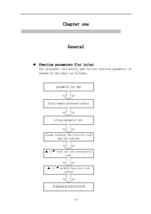
Chapter one Chapter oneGeneral GeneralFunction parameters flat in/out Function parameters flat in/outThe procedure that modify and restore function parameter isshowed in the chart as follows:1.1 E very parts name very parts nameThis part will introduce G7 series inverters ’ every parts name, local keypad and remote keypad ’s parts name and the function.1.1.1 Every parts name of the Every parts name of the AMB AMB AMB--G7G7 series inverters series inverters series invertersG7 series inverters (i.e. 3.7KW) profile and every parts name are shown in chart 1-1.Mounting holeLocal keypad Front coverChart 1-1 G7 series inverters profilesOpen the terminal cover, the control circuit terminals and the main circuit terminal are shown in 1-2 chart.1.1.2 Every parts name of local keypad Every parts name of local keypadEvery parts name of local keypad and function is shown in fig. 1-3 and table 1-3.Main box Die cast aluminum radiatorTerminal coverLED monitorUnit showing lights State showing lights AdjustorOpen Operation keysChart 1-3 every parts name of local keypadEvery parts name of remote keypad1.1.3Every parts name of remote keypadEvery parts name of the remote keypad is shown in fig. 1-4. Remotekeypad functions are same with local keypad.State displaying lights LED monitorUnit displaying lights Crystal displayingAdjustorOperation keyFig.1-4 every parts name of remote keypaddigital input is activeness, then for-ward to choose preference input, whichis keypad digital adjustor function.DecrementBackward to chose function code or its content.As displaying function code , backward to chose parameter setting or error monitor function code.As parameter setting state, if dis-playing the content of function code, backward to chose the content value of the function code, meanwhile the LED digital tube twinkling.As the inverter running, if the keypad digital input is active, then backward to choose preference input, which is keypad digital adjustor function.StoreAs parameter setting, store the content value of the parameter setting function code. As the inverter running, forward to chose running monitor function code.RunningAs applying keypad control mode, start the inverter.Stop/resetAs applying keypad control mode, stop the inverter.As parameter setting, restore the content of the function code. As displaying parameter setting function code, shift between F10 and F66 function code.From error state backward to parameter setting state.Chapter TwoAssembly wayIn this chapter, we will descript the items, which the user must as-sure when they get the AMB-G7 converters machine at first.2.1 Product assurance2.1.1 Label description2.2 Outline dimension and assembly dimension2.3 The requirements of assembly place and management2.3.1 assembly present2.3.2 environment temperature2.3.2 precaution2.4 Assembly direction and space2.5 Remote keyboard and port’s assembly and disassembly2.1 Products assuranceCautionTo damaged or lacking of component, don’t assemblyWhen you get the products, assure the items at first please, as fol-lows:Table 2-1 assurance itemsAssurance items Assurance wayIf the converter consist with the ordered Please assure the label in the sideDamaged or not Check the ampereTight parts loosen or not Check it by screwdriverIf the non-performance have occurred, please no heisted to contact the franchiser or Ambition Company.2.1.1 label description LabelThe description of the converter’s typesCom. code Series code Max. Match motor power Input powerAMBG7 series P7 series Z7 series M7series0R7: 0.75kw 1R5: 1.5kw 2R2: 2.2kw 3R7: 3.7kw 011:11kw280:280kwS2: single phaseT3: Tri-phase T6: tri-phaseMODEL : AMB-G7-3R7T3INPUT : AC 3Φ 380V 50Hz-60Hz OUTPUT : AC 3Φ 9.6A 0-400Hz SER NO : AMBITION ELECTRONICS CO.LTD 工厂编号Table 2-1Type W W1 H H1 D D1 D2 D3 D AMB-G7-0R7T3/S2AMB-G7-1R5T3/S2AMB-G7-2R2T3/S2AMB-G7-3R7T3150 135 220 205 160 94.5 169 119 5.3AMB-G7-5R5T3AMB-G7-7R5T3200 186 300 284 165 - 173 102 6.4AMB-G7-011T3 AMB-G7-015T3 250 234 360 342 212 - 222 142 7Table 2-2Type W W1 H H1 H2 D D1 D2 DAMB-G7-018T3290 200 520 500 475 265 275 215 10AMB-G7-022T3AMB-G7-030T3AMB-G7-037T3348 240 587 567 547 293 303 246 10AMB-G7-045T3AMB-G7-055T3415 300 720 695 670 310 320 245 12AMB-G7-075T3AMB-G7-093T3540 460 925 902 860 295 305 230 12AMB-G7-110T3AMB-G7-132T3AMB-G7-160T3柜机600(L)X600(W)X1800(H)AMB-G7-200T3AMB-G7-220T3柜机660(L)X600(W)X2000(H)AMB-G7-245T3AMB-G7-280T32.3 The requirements of assembly placeCaution1.during transport, please hold the bottom of converter’sIf hold the cover only, then main body drop down maybe occur to cause feet damaged.2. Please mount the converter’s on no combustibility mate-rialBoard.Mount the converters on combustible material body, maybe cause fire.3.The above two converter’s share with the cupboard, set thecold fan please, and make the air temperature keep below 40℃.Being overheat, cause fire or other accidents.Please mount the AMB-G7 converters in these applying scopes and keep the suitable condition, as follows:2.3.1 mounting placeMounting locale must meet the undermentioned conditions:●good air condition in room●environment temperature -10℃-40℃, the nude-10℃-50℃.●as possible as avoid high temperature and high humidity, hu-midity less than 90%RH, no condense water.●Don’t mount on combustible material such like woods.●Don’t shine by sunlight directly.●no combustible, corrosive gas and liquid.●no dust, oleaginous dust, float fiber and metal particle.●mount base strong or no shake.●no electromagnetism interfere, far from interfere source.2.3.2 Environment temperatureTo improve the reliability of converter’s run, please mount it in a good air condition place. If a converter must be used in a enclose box, please mount cool fan or cool air-condition, and keep the en-vironment temperature less than 40℃.2.3.3 PrecautionDuring mounting operation, please cover the converter the anti-dusts cover. Metal fragment producing in this operation like2.5 Remote keypad and connectors mounting and dischargeAs the converter’s place is not the same with the operation place, can take remote keyboard and its extend cable. Remote keypad linking with the ports follows as:●Discharge front coverUse screwdriver to pick out the screws fixing the front cover, put up the cover follow the direct indicated by arrow. Shown in fig 2-4.●linking with the remote keypad, extension cable and terminals. Draw out the extension cable of the remote keypad, control circuit cable and mains circuit from rubber ferrule, shown in fig 2-5.As the remote keypad cable extension is more than 10m, the +5/50mA auxiliary power connecting remote keypad outside is must.●mount the front coverAs the remote keypad and terminals connecting finished, remount-ing front cover steps opposite to the above steps.That is, embed the cover in notch of mains, and press the bottom of front cover, until to the “click” can be listen, then fix the screw us-ing the screwdriver. Shown in fig2-6.Chapter 3ConnectingThis chapter introduce the connector description, mains circuit connector, mains circuit connector specify, control circuit and con-trol circuit description.3.1 the connecting of surrounding device3.2 connecting chart3.2.1 15KW and the below specify G7 converters connector3.2.2 18.5KW and the above specifies G7 connector chart3.3 the compose of terminals3.4 mains circuit terminals connecting3.4.1 mains circuit cable dimension and press ion ports3.4.2 mains circuit terminals function3.4.3 mains circuit arrangement3.4.4 standard connecting chart3.4.5 mains circuit connecting way3.5 control circuit terminals connecting3.5.1 control circuit cable dimension and press ion ports3.4.2 control circuit terminal function3.4.3 control circuit arrangement3.4.4 standard connecting chart3.4.5 control circuit cautions3.6 checkingDanger1. Before connecting, ensure input power have been cut off. Cause shock and fire accident2. Only the electric engineer professional operation can be allowed.Cause shock and fire accident.3. Grounding must be reliability.(380V grade: exp. 3rd grounding).Cause shock and fire accident.4. After connecting the emergency brake ports, checking is must.Cause damaged. (Take responsibility by user self).5. Don’t touch the output connector directly; the output connector don’t be connected to the shell, output connec-tors don’t be connected each other.Caution1. Please ensure if the normal voltage of AC mains circuit power keep with the converters.Cause shock and fire accident.2. Don’t have endured voltage experiment to converter. Cause the semi-silicon damaged.3. Connecting the brake resistance or brake unit.Cause fire accident.4. Please the specify screwdriver to tight connectors. Cause fire accident.5. Please don’t connect the input power wires with output U, V, W connectors.If the voltage adds on output connectors, cause to damage the inner of converter.6. Don’t connect the shift capability or LC\RC noise filter into output circuits.Maybe damage the inner of converter.7. Don’t connect the ele-maganetic switch or ele-maganeticcontactor into output circuit.As the converter is running with load, ele-magnetic switchand magnetic-magnetic contactor working produce wavecurrent that intrigue the over current protection.8. Don’t dismount the front cover; only dismount the termi-nals cover during linking operation.3.2 connecting chart3.2.1 15KW and the below types G7 series inverters connecting chart be showed as chart 3-2.3.2.2 18.5KW and the above types G7 inverters are showed as chart 3-3. If the inverters operation is through keypad, droved the3.3 compose of the connectersThe terminals of G7 series inverters are including control circu-late terminals and main circulate terminals, its function are fol-low as:Control circulate terminalsa)Analog input: keypad adjustor (local or remote keypad) 0-5V, 0-10Vvoltage source VS, VF, 4-20mA current source IS, IFb)on/off input:RUN、F/R、JOG、FRS、RST、X1、X2、X3、X4、X5。
G7起重专用变频器补充说明书---合订本
正式的矢量控制通用变频器200V 级 0.4~110kW(1.2~160kVA) 400V 级 0.4~300kW(1.4~460kVA)通用变频器起重专用软件 Varispeed G7使用说明书软件No.(VSG12511X)软件No.(VSG12611X)经验1:改控制板的功率后返回时,直接出现T 菜单,改O2-06=0(无面板可运行)后就可显示U 菜单 45改成160KW2003.06.13<7>资料编号 E Z Z 810018目 录页1.基本规格 12.电气品规格 13.相互连接图 24.从标准变频器中改变的项目、参数一览表 35.试运行 296.追加功能的说明 307.故障表示的内容和处理(追加、改变部分) 48 附录1.参数的计算方法 50 附录2.检查要点 54 附录3.调整顺序 56 附录4.参数一览表 57变频器面板铭牌例起重专用晶体管变频器Varispeed G7(特殊规格形)的软件No.是VSG12511□,VSG12611□。
(2) 软件No.面板铭牌上的SPEC 栏用810018表示 (1) 变频器的型号 型号和标准品相同内置起重专用软件的通用变频器装置Varispeed G7的变频器型号和软件No.如下所示。
2.3 专用型号PG-X2 PG-B2 PG-D2 PG-A2 (3) 速度控制用的外选件(连接4CN) D0-02CD0-08 AO-12 AO-08 (2) 监视用的处选件(连接3CN) DI-16H2AI-14B AI-14U DI-08 (1) 频率指令设定用的外选件(连接2CN) 2.2 能连接的外选件通用变频器装置Varispeed G7 2.1 构成器械2. 电气品规格② 内置起重专用软件的变频器,有外部的顺控和参数设定不良的场合,会发生顺控错误(SE1~SE4)。
① 有关操作器的使用方法,自学习方法,参考Varispeed G7的使用说明书(TO-S616-10.60)。
G7说明书_1_chapter更改内容

第1章概要本章概要地介绍了AMB-G7变频器的功能及各部件名称。
1.1 功能概要说明1-2 1.1.1 AMB-G7变频器型号及规范 1-11.1.2 控制方式 1.1.3 功能 1.2 各部件名称1.2.1 AMB-G7变频器的各部件名称 1.2.2 本机键盘的各部分名称 1.2.3 远控键盘的各部分名称 1-31-5 1-51-8 1-8 1-9 1-91.1 功能概要说明AMB-G7系列变频器是适用于多种工况的高品质、低噪声、多功能通用变频调速器。
该变频器具有以下特点:采用优化空间矢量PWM控制,输出电流谐波成分小,运行平稳,效率高。
采用最新一代IGBT功率模块,最大载波频率达16kHz,静音运行。
瞬时输出电压自动调整,即使输入电网存在较大的波动,输出电压也基本保持不变。
过流、过载和过压故障后,3次重试运行。
数字键盘、模拟电位器、电压源、电流源、程序运行、摆频运行、计算机接口等多种输入方式,控制方式灵活、方便。
电流限幅、过压失速、回升制动、转速追踪平滑再启动等功能,适应各种应用场合。
内置PID调节器,闭环控制系统结构简单。
内置RS-485标准通讯接口,提供标准通讯协议和计算机联网控制操作软件。
液晶字符、图形显示,中、英文显示方式随时设定,人机界面友好。
双键盘互动切换控制,本机、远程操作自由选择。
保护功能完善,变频器发生短路、过流、过载、过压故障时,系统均能即时保护。
全系列模具化生产,外形美观,结构紧凑。
1-21-31.1.1 AMB-G7变频器型号及规范AMB-G7系列变频器有220V 和380V 两种电压级别。
适用电机功率范围为:0.75∽280kW。
P7系列变频器的适用范围:三相380V,18.5∽280kW,其额定电流与G7系列变频器一致。
变频器的最大输出电压与输入电压相同。
AMB-G7变频器的型号如表1.1所示。
表1.1 AMB-G7变频器型号电压级别型号 适用电机功率(kW)变频器额定输出电流(A) AMB-G7-0R7S2 0.75 4.5 AMB-G7-1R5S2 1.5 7 220V 级 单相AMB-G7-2R2S2 2.2 11 AMB-G7-0R7T3 0.75 2.5 AMB-G7-1R5T3 1.5 4.8 AMB-G7-2R2T3 2.2 6.2 AMB-G7-3R7T3 3.7 9.6 AMB-G7-5R5T3 5.5 14 AMB-G7-7R5T3 7.5 18 AMB-G7-011T3 11 27 AMB-G7-015T3 15 34 AMB-G7-018T3 18.5 40 AMB-G7-022T3 22 46 AMB-G7-030T3 30 61 AMB-G7-037T3 37 75 AMB-G7-045T3 45 90 AMB-G7-055T3 55 110 AMB-G7-075T3 75 150 AMB-G7-093T3 93 176 AMB-G7-110T3 110 215 AMB-G7-132T3 132 256 AMB-G7-160T3 160 309 AMB-G7-185T3 185 348 AMB-G7-200T3 200 387 AMB-G7-220T3 220 420 AMB-G7-245T3 245 470380V 级 三相AMB-G7-280T3280530AMB-G7系列变频器的技术规范见表1-2所示。
安邦信G7变频器说明书
前言感谢您使用安邦信公司AMB-G7/P7系列变频器。
AMB-G7/P7系列变频器是AMB-G5系列变频器的升级产品,在原有功能基础上,增加了内置PID 调节功能、计算机网络接口功能、中英文液晶显示功能、故障重试功能、静音运行功能及本机键盘与远控键盘自由切换功能,使其应用领域更为广泛,操作更加灵活,运行更加稳定,是我公司自主开发的又一高科技产品。
本产品满足GB-T12668-1990《交流电动机半导体变频调速装置总技术条件》之要求,通过了国家电控配电设备质量监督检验中心的质量检验,并通过德国TUV之ISO09001:2000质量体系认证。
在使用ABM-G7/P7系列变频器之前,请您仔细阅读本使用说明书,并请妥善保存。
与安全有关的符号说明错误使用中,会引起危险发生,可能导致人身伤亡。
危险错误使用时,会引起危险发生,可能导致人身轻度或中度的伤害或设备损坏。
安全注意事项llll3.运行中,请勿检查信号。
会损坏设备。
4.请勿随意改变变频器的设定,该系列变频器在出厂时已进行了适当的设定。
会引起设备的损坏。
ll警告标志的内容和安装位置本系列变频器,在端子外罩上印刷了警告标志,使用时请一定要遵守所要求的内容。
警告标志印刷位以AMB-G7-3R7-T3系列警告标志的内容---仔细阅读使用说明书---通电中及切断电源后10分钟内,请勿拆卸端子的外罩。
---Read the instruction manual。
---Do not open the teminal covue while power isapplied or for 10 minutes after power has beenremoved。
总目录第1章概要第2章使用方法第3章接线第4章双键盘互动操作第5章功能代码参数说明第6章试运行第7章故障对策第8章保养和维护第9章选配件第10章附录1-1 2-1 3-1 4-1 5-1 6-1 7-1 8-1 9-1 10-1详细目录1.1功能概要说明1.1.1AMB-G7/P7变频器型号及规范1.1.2控制方式1.1.3功能1.2各部件名称1.2.1AMB-G7/P7变频器的各部件名称1.2.2本机键盘的各部分名称1.2.3远控键盘的各部分名称2.1产品确认2.1.1铭牌说明2.2外形尺寸和安装尺寸2.3安装场所要求和管理2.3.1安装现场2.3.2环境温度2.3.3防范措施2.4安装方向和空间2.5远控键盘和端子的安装及拆卸3.1外围设备的连接3.2连接图3.2.115kW及以下规格G7/P7变频器连接图3.2.218.5kW及以上规格G7/P7变频器连接图3.3端子排组成3.4主回路端子接线3.4.1主回路电缆尺寸和压线端子3.4.2主回路端子功能3.4.3主回路组成3.4.4标准接线图3.4.5主回路接线方法3.5控制回路端子接线3.5.1控制回路电缆尺寸和压线端子3.5.2控制回路端子功能3.5.3控制回路接线图3.5.4控制回路接线注意事项3.6接线检查1-2 1-31-11 1-112-22-3 2-52-6 2-73-4 3-4 3-53-8 3-3 3-6 3-163-19 1-7 1-7 1-12 1-12 2-2 2-5 2-5 2-5 3-8 3-9 3-9 3-10 3-11 3-16 3-16 3-18 3-194.1键盘功能4.1.1本机键盘的功能4.1.2远控键盘的功能4.2键盘操作方式4.2.1参数设定4.2.2运行监视4.2.3故障监视5.1功能代码表5.1.1参数设定功能代码表5.1.2运行监视功能代码表5.1.3故障监视功能代码表5.2功能代码参数介绍5.2.1参数设定功能代码5.2.2运行监视功能代码5.2.3故障监视功能代码5.3PID闭环控制6.1试运行的顺序6.2试运行的操作6.2.1闭合电源6.2.2通电状态确认6.2.3空载运行6.2.4负载运行7.1故障内容7.2故障分析7.2.1参数不能设定7.2.2电机旋转异常7.2.3电机加速时间太长7.2.4电机减速时间太长7.2.5变频器过热7.2.6电磁干扰和射频干扰7.2.7漏电断路器动作7.2.8机械振动8.1保养和维护8.1.1日常维护4-2 4-7 5-2 5-95-376-3 6-47-2 7-38-3 4-2 4-5 4-7 4-14 4-17 5-2 5-8 5-8 5-9 5-34 5-35 6-4 6-4 6-5 6-5 7-4 7-4 7-4 7-5 7-5 7-5 8-3 7-3 7-38.1.2定期维护8.1.3定期保养8.1.4变频器的维修9.1制动部件9.1.1制动单元型号9.1.2制动电阻型号9.1.3制动电阻选用9.1.4制动单元连接9.2远控键盘及延长电缆9.2.1远控键盘9.3通讯协议及监控软件9.3.1通讯协议及监控软件9.3.2RS232-485总线适配器9.3.3RS485总线分配器9.3.4RS485总线电缆9.3.5RS232总线电缆10.1附录10.1.1中英文显示对照表9-29-6 9-610-2 10-2 8-3 8-4 9-2 9-2 9-3 9-4 9-6 9-6 8-4 9-6 9-7 9-7 9-6第1章概要本章概要地介绍了AMB-G7/P7变频器的功能及各部件名称。
G7说明书_4_chapter更改内容
功能代码。
参数设定状态,若指示功能代码内容,减小
减小键 参数设定功能代码内容值,同时 LED 数码管
显示闪烁。
变频器运行时,若键盘数字输入有效,减小
参考输入给定或 PID 数字输入,即数字式键
盘电位器功能。
存储键
参数设定时,存储参数设定功能代码内容值。 变频器运行时,增加运行监视功能代码。
运行键 键盘控制方式时,启动变频器运行。
4-3
AMB-G7 系列通用变频器使用说明书
双键盘互动操作
按键
本机键盘按键的功能如表 4-1 所示
表 4-1 本机键盘按键的功能
按键名称
按键功能
功能代码与功能代码内容切换键。
参数设定时,切换参数功能代码与其内容;
移位键
变频器运行时,切换运行监视功能代码与其 内容;
变频器故障时,切换故障监视功能代码与其
4-7
AMB-G7 系列通用变频器使用说明书
双键盘互动操作
01 参考输入 09 数字参考输入
10 控制方式 11 输入给定选择
66 参数设定方式 67 输入端子选择
67 输入端子选择 68 输出端子选择
67 输入端子选择 范围:0-4
0 多段速控制
图 4-3 快速查询功能代码操作流程
功能代码查询
功能代码查询除用快速查询功能代码方法外,还可 通过▲或▼键操作查询所需功能代码。G7 变频器的▲键 和▼键具有积分功能,即按键开始时,功能代码或其内 容值增加或减小的幅度较小较慢,若按键一直闭合,其 幅度逐渐加大,直至对应参数值的最大或最小值。若按 键之前,功能代码为 F01,其加减过程如下:
4. 监视变频器直流母线电压。
5. 监视变频器程序运行时间和运行段数(程序运行
G7中文说明书 (new)

144/430/1200MHz 三波段调频电台DJ-G7目录1.可选及标配附件清单 (6)2.特性 (6)3.附件使用 (7)3.1 天线 (7)3.2 安装手绳 (7)3.3 皮带夹 (7)3.4 电池 (8)3.5 充电器 (8)3.6 充电底座 (9)3.7 电池使用注意事项 (9)3.8 电池盒 (10)3.9 电池充电图标指示 (10)4.机身各部分按钮说明 (11)4.1.1 顶部和前部 (11)4.1.2 侧面 (12)4.1.3 键盘 (12)4.2 显示屏 (13)5.基本操作 (14)5.1 打开电台 (14)5.2 选择频率 (14)5.3 调节输出音量 (15)5.4 调节静噪 (15)5.5 监听功能 (16)5.6 静音功能 (16)5.7 选择操作波段 (16)5.7.1 单波段操作 (17)5.7.2交换主副波段频率 (17)6.操作模式 (17)6.1 在VFO模式下操作 (18)6.2 设置频率步进 (18)6.3 以1MHz步进快速调节频率 (18)6.4 使用键盘输入频率 (18)6.5 预设模式操作 (18)6.6 接收范围 (19)6.7 发射操作 (19)6.8 双音频呼叫 (19)6.9预设中继参数 (19)7.内存频道模式 (20)7.1 内存频道类型及使用方式 (20)7.2 写入频道频率 (20)7.3 使用保存的数据 (22)7.4 删除已保存的频道 (22)7.5 移动频道数据 (22)7.6 编写发射检测段频道数据 (22)7.7 保存紧急呼叫频道数据 (23)7.8 定义快速频道调用按键 (23)7.8.1 定义快速调用频道 (23)7.8.2 使用快捷频道调用按键 (23)7.9忽略频道功能 (23)7.10 频道命名 (23)8.键盘功能分配 (26)8.1 进入设置 (26)8.2 发射功率调整 (26)8.3 自动衰减设置 (27)8.4 调制模式选择 (27)8.5 亚音静噪和数字亚音选择 (27)8.5.1 亚音频静噪功能 (27)8.5.2 数字亚音设置 (28)8.6 频谱表功能 (29)8.6.1 频率模式下的频谱 (29)8.7 改变步进 (30)8.8 麦克风增益调节 (30)8.9 使用紧急呼叫频道 (30)8.10 优先扫描功能 (31)8.11 差频设置 (31)8.12 将频道数据拷贝到频率模式 (31)8.13 跨段中继模式 (31)9 快捷功能 (32)9.1 键盘锁 (32)9.1.1 如何使用键盘锁 (32)9.1.2 当锁定后可执行的操作 (32)9.2 扫描功能 (33)9.3 频率模式扫描 (33)9.4 预设模式扫描 (33)9.5 频道扫描 (34)9.6编程扫描 (34)9.7 亚音扫描 (34)9.8 DCS数字亚音扫描 (35)9.9 双重扫描 (35)9.10 发射检测功能 (35)10 设置菜单 (36)10.1 屏幕显示设置 (37)10.1.1 语言选择 (37)10.1.2 背光延时 (37)10.1.4 屏幕对比度 (38)10.1.5 字体大小 (38)10.1.6 字体加粗 (39)10.2 电源和电池 (39)10.2.1 自动关机设置 (39)10.2.2 省电模式 (40)10.2.3 电池类型 (40)10.3 音效 (40)10.3.1 音效等级 (40)10.3.2 提示振铃 (41)10.3.3 结束音 (41)10.4 发射设置 (42)10.4.1 声控发射 (42)10.4.2 TOT发射时间控制 (42)10.4.3 TOT惩罚 (43)10.4.4 BCLO(繁忙信道锁定) (43)10.4.5 亚音频速率 (43)10.4.6 全双工设置 (44)10.5 中继设置(T版) (44)10.5.1 自动中继设置 (44)10.6 DTMF设置 (45)10.6.1 自动拨号 (45)10.6.2 DTMF等待时间 (45)10.6.3 DTMF 首字符延时 (46)10.6.4 DTMF速率时间 (46)10.6.5 DTMF 时间间隔 (46)10.7 接收设置 (47)10.7.1 AM天线设置 (47)10.7.2 时钟偏移设置 (47)10.7.3 亚音静噪优先级设置 (48)10.7.4 数字亚音DCS设置 (48)10.7.5 TSF操作设置 (48)10.7.6 接收范围 (49)10.7.7 预设模式设置 (49)10.8 内存设置 (49)10.8.1 内存段链接设置 (49)10.8.1 内存段链接设置 (49)10.8.2 写保护功能 (50)10.9 扫描设置 (50)10.9.1 扫描模式设置 (50)10.9.2 扫描忽略设置 (51)10.9.3 优先监听中断时间设置 (51)10.10 窃听器检测设置 (52)10.10.1 激活方式 (52)10.10.2 检测模式设置 (53)10.10.3 灵敏度设置 (53)10.11 按键定义 (53)10.11.1 键盘锁定模式设置 (53)10.11.2 监听键模式设置 (54)10.11.3 监听模式选择 (54)10.11.4 设置波段监听选项 (55)10.11.5主副波段顶部按钮设置 (55)10.11.6 顶部旋钮功能设置 (55)10.11.7 重定义功能键 (56)10.11.8 波段间过渡选项 (56)10.11.9 退出设置 (57)11 频道模式 (57)12 复制数据/PC管理 (57)12.1连接电缆 (57)12.2操作主机发送数据 (58)12.3 操作副机接收数据 (58)12.4 数据通讯 (58)12.4.1 数据通讯连接 (58)13 复位 (59)13.1 部分复位 (59)13.2 全复位 (59)14 故障及维护参考 (60)14.1 简单故障处理表 (60)14.2 可选附件 (61)14.2.1 外接耳麦转换电缆(EDS-14) (62)15 参数特征 (63)1.可选及标配附件清单DJ-G7手持机EA-163天线EBP-73锂电池EDC-173座充EDC-170充电器(T版)EDC-151A充电器(E版)EDC-152A充电器(EUK版)EBC-23皮带夹手绳使用手册2.特性1.全双工,可在副波段接收信号是从主波段发射2.三波段收发(144/430/1200MHz)3.主副波段独立操作旋钮,可调节频率/音量/静噪4.超大LCD屏幕,具有良好的可读性和操作性5.支持AM/SW/FM广播模式接收,具备0.5至1300MHz超大接收范围6.内置AM广播接收天线7.支持VOX语音控制发射功能8.两种窃听器检测模式,当检测到目标时将产生振铃和图标提示9.支持电缆复制数据,可从PC编辑和导入配置10.内置标准CTCSS/DCS亚音11.内置ALINCO专利频谱技术12.专用WILD键快速切换使用模式和设置模式3.附件使用3.1 天线1:向右将天线旋转拧入机器顶部天线座2:确认天线安装牢固3.2 安装手绳1.将手绳穿过机身右上部的小孔并回绕3.3 皮带夹入固定螺丝2.确认皮带夹螺丝固定到位3.4 电池1.将电池平放在机身后部对准卡槽向上推入2.推动电池底部锁止钮以免电池脱落移除电池1.先向上推动电池锁止钮,再向下推动电池3.5 充电器该产品使用直流12v充电器对锂电池进行充电,完全充满需要至少5小时1.在机身上装入电池2.连接充电器到电源,将充电头插入机身充电孔或充电底座3.6 充电底座1.连接充电器到电源,连接充电器插头到充电底座2.在充电底座中放入装好电池的机身3.7 电池使用注意事项不可将电池放入有金属杂物的包内 不可将电池放入无保护包装的包内 不可将电池与其他金属杂物混合放置请给每块电池单独包装保护当周边有金属物品时请将电池单独包起3.8 电池盒1.打开电池盒顶盖2.装入4节AA(5号)电池,按照右上图2-3顺序方向操作盖好电池盒盖板3.9 电池充电图标指示LCD右上角为电池电量图标当电池电力满时显示电量减少时显示需要充电时显示使用充电器插入到机身后的充电图标充电时循环显示的图标样例4.机身各部分按钮说明4.1.1 顶部和前部编号名称功能1 主旋钮(上部)VFO频率模式下可调节主波段频率,频道模式下可切换主波段频道,当屏幕显示F图标时可切换设置存储位置2 主旋钮(下部)调节主波段音量,配合其他键可改变设置项目3 副旋钮(上部)VFO频率模式下可调节副波段频率,频道模式下可切换副波段频道,当屏幕显示F图标时可切换设置存储位置4 副旋钮(下部)调节主波段音量,配合其他键可改变设置项目5 显示屏显示主机信息6 键盘可输入频率或修改设置内容7 天线座(SMA)安装天线8 耳麦接口连接外部耳麦9 主波段收发指示灯主波段收发指示,发射时为红灯,接收时为绿灯10 副波段收发指示灯副波段收发指示,发射时为红灯,接收时为绿灯11 麦克风发射时请对此位置保持5厘米左右距离4.1.2 侧面编号名称说明12 PTT按键按下PTT键发射,放开转入接收模式13 MONI监听键LAMP背光灯当按下MONI键时,关闭主机静噪控制,当按压FUNC 键后再按MONI键,可调节背光自动关闭延时时间14 电源开关打开/关闭主机15 DC直流充电口可连接各类适用的充电器(7-16V,最大3A电流)4.1.3 键盘按键功能当按下FUNC键后按该键1秒钟以后按住该键并调节顶部旋钮时1 输入1 WILD键频道模式下快速选2 输入2 发射功率设置择存储位置3 输入3 ATT衰减设置4 输入4 选择接收模式5 输入5 亚音/数字亚音选择6 输入6 频谱表设置7 输入7 步进设置8 输入8 麦克风增益9 输入9 快速返回CALL频率0 输入0 优先. 输入小数点在频道模式下快速清除ENT 结束输入中继设置MAIN 主波段内切换频段差频设置主波段单双显切换快速波段选择SUB 副波段内切换频段主副波段交换副波段单双显切换V/P/M 切换操作模式频道写入/修改/命名SCAN 扫描M-V切换扫描模式选择FUNC 功能键切换显示F图标键盘锁定以1MHz步进调节频率4.2 显示屏编号图例功能描述1按下F键/键盘锁定2定时关机激活3 操作波段4 自动衰减打开5VOX语音发射控制打开6设置有差频收发时显示7发射亚音/接收亚音/数字亚音图标8 设置了振铃功能后显示9 省电模式标志10 电池电量表示11主波段频率12 接收模式显示(AM/FM/NFM/WFM)13 副波段频率显示14 显示被存储的频道存储位置15 显示被存储的频道的存储频道16发射功率或接收信号强度指示17 切换显示静噪被打开或关闭18 操作模式指示5.基本操作5.1 打开电台按住键1秒钟以上打开主机电源,重复该操作关闭主机电源5.2 选择频率选择主波段频率旋转主波段顶部旋钮上部(左旋钮(1))选择副波段频率旋转副波段顶部旋钮上部(右旋钮(3))5.3 调节输出音量音量共分为21级别(0-20),默认设置是10旋转主波段旋钮下部大圈(2)位置调节副波段音量旋转副波段旋钮下部大圈(4)位置5.4 调节静噪向下按主波段顶部旋钮(1),旋转(1)即可调节静噪主波段静噪调节向下按主波段顶部旋钮(3),旋转(3)即可调节静噪5.5 监听功能监听键可设置两种模式(按下/按住),请查看“监听键模式设置”章节两种模式的差别:按下(按下MONI键,静噪打开,松开MONI键后结束监听)按住(按一次MONI键,持续打开静噪,再按一次MONI键,关闭监听功能)当监听功能激活时,无论在哪种模式下,所设置的亚音/数字亚音都将失效。
G7 设备用户指南说明书

G7Getting Started:G7’s Hardware and Gas DetectionCharging lightCartridge (Standard, Single-gas(G7c only)OK buttonUp button LCD screen Speaker Latch pull*Latch push**Real-time customers only, if you are interested in these features, please contact your sales representative.Down button Connectivity lightYOUR G7OKCHARGINGPOWERING ONUSING G7’S MENUTo charge the battery, insert the micro USB cable into the removable charging clip, then slide the clip onto the charging port at the bottom of your G7.A solid red light at the bottom of the device confirms your G7 is charging. The LCD screen will show charging and battery levels.Blackline recommends that you fully charge your device after every shift.Micro USB cableRemovable charging clipChargingport G7’s menu is where you can access different items, such as gas options, messages, settings and advanced info.To use G7’s menu:1.Press OK once to wake up G7’s screen2.Press OK again to enter the main menue the up and down arrow keys to navigate to the selection you would like4.Press OK to select a menu item5.Repeat as necessaryOK buttonPress to open the main menu andconfirm menu selections.Up and down arrow buttons Press to navigate the menu.Visit to download the technical user manual with descriptions of how to use and configure your device features and specifications.CUSTOMER CAREFor technical support, please contact our Customer Care team.North America (24 hours)Toll Free: 1-877-869-7212 | ***************************United Kingdom (8am-5pm GMT)+44 1787 222684 | *****************************International (24 hours)+1-403-451-0327 | ***************************LEARN MORE0076/R10/2018-08-13What does the green light indicate?G7’s green connectivity light has two states:A flashing connectivity light indicates that your G7 is storing data. It is not currently connected to the network and will send data when the light is solid.A solid connectivity light indicates that G7 is actively transmitting data and is connected to the Blackline Safety Network.To turn on G7, press and hold the power button for two seconds. G7 will beep and vibrate when it turns on.NOTE: If you are using real-time features,your safety is only monitored when the connectivity light is solid.GAS DETECTION BUMP TEST AND CALIBRATIONGAS ALERTS & ALARMSWhat is a calibration?Gas sensors periodically need to be calibrated by applying a known concentration of gas for a set amount of time. This ensures the gas sensor can accurately detect gas levels. The calibration schedule depends on your company’s safety policy. Blackline recommends not exceeding 180 days without a calibration.What is a bump test?It is safe practice to regularly test gas sensors by applying the target gas. G7’s bump test also tests the operation of light, sound and vibration indicators. The bump test schedule depends on your company’s safety policy.Zeroing sensorsIf G7 is not reading zero (or baseline) and you know you are in an atmosphere with no gas, your gas sensor readings may have shifted. If this happens you can zero your sensors to reset the baseline. Zeroing should only be completed if you are certain you are in a safe environment.G7 devices with a Single or Multi-gas cartridge are capable of detecting gases in your environment.G7 monitors your environment and will notify you of gas exposure with a yellow warning or red alert.All gas settings are customizable withinBlackline Live. Speak to your safety supervisor to learn about how your G7 gas features are configured.M ul t i -g a s G 7Si n g l e -g a s G 7Low warning alarm for gasIf a sensor detects a low concentration gas level.UL (under limit)If a sensor’s baseline shifts and is unable to obtain an accurate gas reading.Sensor errorIf a sensor stops working for any reason.Calibration and bump testIf a sensor is due for a calibration or bump test.High alert for gasIf a sensor detects gas levels above the maximum gas concentration.STEL (short term exposure limit) If a sensor detects you have reached the short-term exposure limit configured.TWA (time weighted average)If you have reached the average gas amount of repeated gas exposure in an eight-hour period.OL (over limit)If excessive amounts of gas are detected and sensors can’t provide an accurate gas reading.YELLOW WARNING ALARM RED ALERTTubingHow to manually bump or calibrate single, multi-gas and pump cartridges:1.Attach calibration cap to one end of the tubing 2.Attach the other end of the tubing to a fixed flow regulator on your calibration gas cylinder 3.Attach the calibration cap to the cartridge 4.Press OK to access the main menu ing the up and down arrows,navigate to gas options 6.Select OK to enter the gas options menu e the OK button to select bump test or calibration 8.Follow the instructions on G7’s screen to complete the calibration or bump testG7 DockBump tests and calibrations can also be done using G7 Dock, where the process is automated for you.To bump test or calibrate with G7 Dock:1.Place G7 in Dock at a 30 degree angle 2.Lower the top of G7 into G7 Dock,pressing until you hear a click 3.Close Dock’s lid4.Select bump test or calibration from the Dock menu on G75.Allow G7 Dock to run and remove G7when the screen prompts youIf you do not have G7 Dock and are interested in ordering, please contact your distributor, sales representative, or our Customer Care team.。
华为G7手机使用手册说明书

声明Copyright ©2006华为技术有限公司版权所有,保留一切权利。
非经本公司书面许可,任何单位或个人不得以任何方式摘抄、复制本书内容的部分或全部,并不得以任何形式传播。
®、HUAWEI®、华为®均为华为技术有限公司的商标。
对于本手册中出现的其它商标和产品名字,由各自的所有人拥有。
由于产品版本升级或其它原因,本手册内容会不定期进行更新。
除非另有约定,恕不另行通知。
本手册仅作为使用指导,本手册中的所有陈述、信息和建议不构成任何明示或暗示的担保。
安全须知使用话机前,请仔细阅读本节内容,也请让您的孩子了解这些内容,以确保正确和安全地使用话机。
有关更详细的信息,请参阅本手册中的“安目录1 了解您的话机 (1)话机前视图 (1)话机按键功能 (2)屏幕图标显示 (3)2 开始使用话机 (4)安装电池 (4)取出电池 (4)插入和取出PIM卡 (4)电池充电 (5)开机和关机 (5)切换语言 (5)拨打电话 (5)接听/拒接来电 (6)通话过程中的操作 (6)手动锁键盘 (6)3 输入法介绍 (7)输入模式介绍 (7)编辑状态下按键功能说明 (7)拼音模式 (7)笔划模式 (7)字母模式 (7)输入数字 (8)输入符号 (8)4 信息 (9)写信息 (9)设置短信一键通 (9)使用短信一键通 (9)5 电话簿 (10)添加新号码 (10)搜索号码 (10)设置缩位拨号 (10)i6 灵通无绳 (11)灵通无绳业务 (11)模式选择 (11)对码 (11)7 闹钟设置 (13)设置闹钟 (13)取消闹钟 (13)8 呼叫转移 (14)开启无条件转移 (14)取消无条件转移 (14)查询无条件转移设置 (14)更改操作码 (14)9 安全设置 (16)启动拨号锁定 (16)启动PIN码校验 (16)更改PIN码 (16)启动开机锁 (16)更改话机密码 (16)恢复出厂设置 (16)10 菜单树简介 (17)11 常见问题处理 (23)12 安全警告和注意事项 (24)ii1 了解您的话机话机前视图1话机按键功能名称图标说明拨号键拨打电话和接听来电。
- 1、下载文档前请自行甄别文档内容的完整性,平台不提供额外的编辑、内容补充、找答案等附加服务。
- 2、"仅部分预览"的文档,不可在线预览部分如存在完整性等问题,可反馈申请退款(可完整预览的文档不适用该条件!)。
- 3、如文档侵犯您的权益,请联系客服反馈,我们会尽快为您处理(人工客服工作时间:9:00-18:30)。
RF7(G7)安装说明
1、在电脑光驱内放入蓝色的B光盘
2、打开光盘,进入G7文件夹。
如下图:
3、点击‘setup.exe’这个文件,
4、选择好软件点下一步:
5、这里选择定制(可以更改安装路径,默认会装在C 盘)
6、点击更改,选择你要安装的位置
7、建议更改盘符就行(路径切记别用中文哦)
8、安装完后桌面会生成两个图标,1个RF7,一个飞鹰模拟器控制台(飞鹰控制台没用,可以删除掉)
9、点击桌面RF7图标开始运行软件,这里会出来对
话框,要求输入R7及I3序列号。
请输入纸条上的R7及I3序列号
10、输完R7及I3序列号,接着会跳出对话窗口要求输入E1-A1扩展包序列号:
1. 27418829-E1-5140106092
2. 22850737-E2-3850104361
3. 78396652-E3-7440103834
4. 13144997-E4-6630107326
5. 78779710-E5-8790101628
6. 67920032-E6-7880104031
7. 90638630-E7-7730148192
8. 64658044-E8-1910121237
9 35589764-H1-0040109905
10 49778064-A1-0040109998
复制粘贴进去,输入完会提示已激活!
6页
11、接着会有提示:有新版本是否升级,点否,因为你
还没有进行在线注册
12、点击附加选项,进行在线注册,(注册完就可以升级和在线联机了)
13、输入个人信息,红色大框内建议填一个空格即可,中间红色框内自己设置一个密码(自己要记牢),接着点发送信息。
如下图:
14、现在我们进入软件,首选选择控制器(选遥控)
15、点击上面的遥控器图标:
16、选择你的遥控器品牌:
提示:(国产都选FUTABA就行)
17、点击Edit来进行通道映射
18、左边红框内是通道正反项,右边红框内是通道分配
19、以上设置好就可以爽飞了,祝大家飞行愉快!
炸机重启按一下空格键即可。
附凤凰模拟器视频教程链接:(复制到IE打开)/v_show/id_XNDc1MzI4MTE2.ht ml。