LWD国产化项目自然伽马短接的设计与研制
长排工作区三维空间伽玛等值场构建及分析
作者简 介 : 谢欢朋 (9 7一) 男 , 17 , 陕西省 西安 市人 , 学 士, 工程师 , 事铀矿资 源勘查工作 。 从
86 2
晶格 状 三 维 空 间模 型 , 每 个 晶格 体顶 点单 元 在 填充 包 含 坐 标 系统 及 属 性 的 四维 数 据 , 后 从 然 某 一 个 顶 点 开始 向其 他 几个 方 向追 踪 , 到 属 遇 性 等 值 点 处做 出等 值 标 记并 继 续 追 踪 , 完成 所 有 顶 点 追踪 ቤተ መጻሕፍቲ ባይዱ , 将 这 些 等 值标 记按 级别 连 接 再 成线 , 最后 用级 别相 同的线 构造 成面 , 渲染 后 进
合工作区地质资料进行了特征分析。
关键词 : 铀矿勘查 ; 空间伽玛场 ; 三维 等值 图
中图分类号 : P6 18+ 3 . 4 文献标志码 : A 文 章编 号 : 0 5 -9 4 2 1 )70 2 -3 2 803 ( 02 0 -8 60
在热 液脉 型铀矿 区 , 铀矿元 素 往往沿 构 造 、
第3 2卷
21 0 2年
第 7期
7月
核 电子学 与探 测技术
Nu l a e to i s& De e t n Te h oo y ce r El cr n c tc i c n l g o
Vo . 2 No 7 13 .
J l. 2 1 uy 02
长 排 工作 区三维 空 间伽 玛 等 值 场 构建 及 分 析
裂隙、 岩性界面等地方分布和富集 , 并以物理运 移 、 学交 换反应 等方 式 向周 边空 间 扩散 [ 】 化 1 。 随距离的加大 , 其分布强度逐渐降低 , 形成放射 性晕 圈形 态在空 间展 布 。 传统空间伽玛场 的制作一般是手工绘制放 射性晕圈, 以深度不同的几层二维平 面伽玛晕
2010年度河南省工业和信息化科技成果奖获奖项目名单(公示)

王辉、郭敬业、姚斌、李君、张俊花、陈剑波、 韩民、王东方、刘伟、曹晓新、马宏兵、柴建 一等奖 勋、郑如军、张军伟、张耿 焦大宏、叶继明、黄林浩、许海涛、任新强、 史国显、南怀志、王君玲、石亚飞、常丽强、 宋彩玲、吕达、郭谦、王涛、孙晓娜 李文海、罗干平、张金岭、张德聚、冯焕丽、 孙浩欣、许保卫、李营超、米永祥 李新宝、徐丽、周文强、刘国际、温淅华、郭 红玲、李凯慧、王海荣、杨光瑞、雒廷亮 陈建中、刘文朝、沈丽娟、祝学斌、王中民、 赵建华、李延峰、刘丙春、张新民、黄文峰、 尹茂、聂倩倩、赵江涛 一等奖 一等奖 一等奖
一等奖
39
一等奖
40
一等奖
41
42
秦海清、李现锋、申 江、洪玉申、张永灿、 胡 城、陈亚楠、刘 斌、张咸忠、 张平卿、 一等奖 许银亮、闫 瑾、杨 英 孙海良、李延河、周 文、司新波、王襄禹、 孟庆妮、齐中立、赵义华、朱 明、柏建彪、 一等奖 李 冰、宋英明、张 旭、曹书凯
43
矿井重点工程决策系统 HNGXS-20101114 研究与实施
河南通和高速公路养护工程 有限责任公司 郑州市豫中轻金属机械有限 公司 河南索凌电气有限公司 平高集团有限公司 华北水利水电学院 郑州大学 中国矿业大学 河南神火煤电股份有限公司 选煤厂 河南省科学院地理研究所 河南省遥感与地理信息系统 重点实验室 建设综合勘察研究设计院 乐凯集团第二胶片厂 河南省煤科院耐磨技术有限 公司 河南省煤炭科学研究院有限 公司 河南工程学院
中国平煤神马能源化工集团 有限责任公司 平顶山煤业集团有限责任公 司中国矿业大学 平顶山天安煤业股份有限公 司 中国矿业大学 煤炭资源与安全开采国家重 点实验室 平顶山天安煤业股份有限公 司十矿 河南理工大学 平顶山天安煤业股份有限公 司十三矿 河南理工大学 中国平煤神马能源化工集团 有限责任公司 平顶山天安煤业股份有限公 司二矿 河南理工大学 河南平禹煤电有限责任公司 中国矿业大学
DSL—I型数字自然伽玛能谱测井仪

DSL—I型数字自然伽玛能谱测井仪
栾士文;王洁
【期刊名称】《石油仪器》
【年(卷),期】1991(005)003
【总页数】6页(P142-147)
【作者】栾士文;王洁
【作者单位】不详;不详
【正文语种】中文
【中图分类】P631.83
【相关文献】
1.自然伽玛能谱测井仪(SGS)及其应用 [J], 张明;王俊;陶吉元;卢超
2.基于FPGA的自然伽玛能谱测井仪的研制 [J], 曾晓丰;周齐志
3.自然伽玛能谱测井仪现场检测器的研制 [J], 蔡晓波;刘东友
4.自然伽玛及自然伽玛能谱测井在沉积盆地古环境反演中的应用 [J], 陈中红;查明;金强
5.自然伽玛测井与伽玛能谱测井的应用现状 [J], 李斌凯;马海州;谭红兵
因版权原因,仅展示原文概要,查看原文内容请购买。
IAEA-277号报告
水吸收剂量校准因子 电离室(剂量计)的空气比释动能校准因子 电离室(剂量计)的空气比释动能校准因子 考虑电离室中心极材料非空气等效的因子 考虑电离室 考虑电离室离子收集未饱和(由于离子复合损失)的因子 温度和气压偏离参考值造成的修正因子
4
hm HVL J air J20 J10
katt kh km ku
Kair Km M ND N D ,W NK NX Pcel Pu Ps PTP P
当测量的电离最大点是在材料 m 中而不是在水中须用的修正因子 半值层 电离室空气空腔中的平均特定电离 源皮距固定时 20 cm 深度和 10 cm 深度的电离比 电离室在校准照射时,考虑其壁衰减(吸收和散射)的因子 考虑电离室空腔中空气湿度的修正因子 考虑电离室壁和平衡帽材料在(校准辐射质下)非空气等效的因子 考虑电离室在校准时和被使用者用于水中测量时 X 射线谱分布变化 的因子 空气的比释动能(kerma) 受照射模体中某点的材料 m 的比释动能(kerma) 电离室测量系统的读数
1.2. 二级标准实验室和二级标准实验室(SSDLs)网的历史回顾
物理测量必须能够溯源到基准,这是通用法则。这样的基准由国家基准实验室和国际剂量局 (BIPM)建造和保存。电离辐射测量中,只有大约 20 个实验室有照射量和吸收剂量基准。一些国家 缺少校准设施导致 IAEA 和 WHO 考虑支持建立“二级标准实验室(SSDLs)”[11-13]。
─ 支持应用剂量学知识创作传播中心和实验室,改善剂量测定,特别是放射治疗剂量测定的精 确性和重复性;
─ 促进成员间的经验交流,接受会员,必要时互相支持; ─ 推动成员间的联系和与剂量学基准实验室(PSDLs)的联系,从而建立与国际辐射测量系统
GAMMA曲线调整

GAMMA曲线调整关于gamma矫正的共享内容1.前言。
2.Gamma问题的产生。
3.基本知识的准备(色温、色域xy值、白平衡)。
4.Gamma矫正对主观效果有何影响。
5.Gamma曲线的测量。
6.Gamma曲线形态的解读。
7.Gamma矫正的原理以及实现。
8.电视机确定效果参数的一般步骤。
一、前言。
Gamma矫正是显示设备根据主要显示器件本身的特性改善整体显示效果的重要技术,我们较早的机型曾经实现过Gamma矫正曲线现场可调节并记忆,但由于我们当时大量使用的LG屏内部含有Gamma矫正电路使其GAMMA性能较好,在后来的一段时间内我们很少调整Gamma参数,由于广辉屏和NEC 等屏的选用导致对Gamma软件矫正需求加强,我们才意识到,实际上这些地方有一些方法可以改善图像细节和色彩的效果。
听说Gamma矫正效果的调节是日系彩电色彩和细节表现效果好的一个重要原因。
二、G amma问题的产生。
对于显示设备,输入的信号将在屏幕上产生三种亮度输出,但是显示设备的亮度与输入的信号不成正比,存在一种失真,如果输入的是黑白图像信号,这种失真将使被显示的图像的中间调偏暗,从而使图像的整体比原始场景偏暗,如果输入的是彩色图像信号,这种失真除了使显示的图像偏暗以外,还会使显示的图像的色彩发生偏移。
gamma就是这种失真的度量参数。
对于CRT显示器,无论什么品牌的,由于其物理原理的一致性,其gamma值的趋势几乎是一个常量,为2.5。
(注意,gamma=1.0时不存在失真),由于存在gamma失真,输入的信号所代表的图像,在屏幕上显示时比原始图像暗。
如下图所示。
(RGB)Gamma1.0时的128阶现象(RGB)Gamma2.5时的128阶现象下面是2.2Gamma曲线的示意图:上图为一典型显示设备的Gamma 曲线非常接近指数函数(注意上图中输入值为数字化的,即通常的RGB值),归一化后我们通常可以用一个简单的函数表达:Output=Input^Gamma。
FIB介绍
307
195
50
364
240
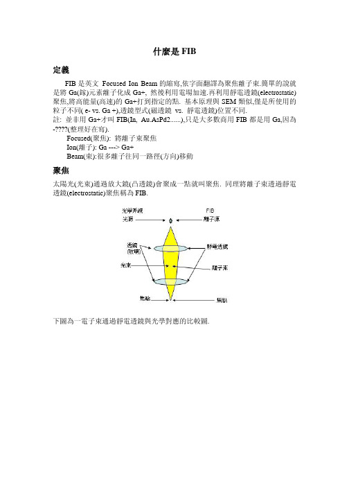
sample 為 Si
表面濺擊(Sputtering):
指 Ga+直接撞擊表面原子將其擊出,有下列幾項要點: Sputtering Rate: 對不同物質會有不同的濺擊速率(下表). 結晶方向不同有不同的濺擊速率.若同一平面有不同的晶粒(Grain)方向,會造成無 法平坦蝕刻(例:Cu). 無法選擇性蝕刻. 被移除的物質回積(redeposition): 無法開高視比的孔洞(high aspect hole),因為被擊出的物質撞到側壁又填回,到一 定深度後就不易再加深. 若回填物為導體,在電路修正時將會造成漏電或短路.
下圖分別顯示:Deflector 工作原理,Scanning Pattern, Rotate Image.
其他:
典型 FIB 系統 [2] : Column 長度 15 cm 2 µA(離子流)從 Source 流出 經過 spray aperture 後約 20 nA 經 limiting aperture 選擇使用 20nA - 1pA Beam Current 離子束與物質作用 離子轟擊
加速器介绍
Introduction to Particle Accelerators國家同步輻射研究中心 周炳榮 Ping J. Chou pjchou@.twPHYS467500— 01Last update: 2007-10-22十年樹木,百年樹人Important Notes to Students: The sole purpose of this lecture notes is meant for classroom use only. Some photographs and graphic illustrations are adapted from various reference literatures, which are NOT to be distributed beyond the classroom use. Acknowledgement: The author is greatly in debt to Dr. Andrew Sessler of Lawrence Berkeley National Laboratory for his generous help and offering of invaluable historic notes on the development of particle accelerators. Dr. Andrew Sessler’s book* on the historic review of the development of particle accelerators is HIGHLY recommended to those who is interested in the physics of particle accelerators and the human stories behind it. One can certainly find some inspiration from his book. * Andrew Sessler and Edmund Wilson, Engines of Discovery –- A Century of Particle Acceerators, (World Scientific, Singapore 2007)The years around 1930 can be marked as the starting point of the accelerator era. Lord Ernest Rutherford can be regarded as the first person to push the development of particle accelerators.Laureates Year Main contribution to the physics of particle accelerators---------------------------------------------------------------------------------------------------------------E.O. Lawrence 1939 the invention of cyclotron and the production of artificial radioactive elements J.D. Cockcroft & 1951 the invention of cascade accelerator and the first E.T.S. Walton disintegration of atomic nuclei by artificially accelerated particles E.M. McMillan 1951 the principle of phase stability (transuranium elements) (in chemistry, shared with G.T. Seaborg ) J. Schwinger ( 1965 the fundamental analysis of properties of synchrotron shared with S. radiation (work on quantum electrodynamics) Tomonaga, R.P. Feynman) L.W. Alvarez 1968 drift tube linear accelerator (development of hydrogen bubble chamber) C. Rubbia & 1984 the invention of stochastic cooling for antiprotons S. Van der Meer (discovery of W/Z particles)Mechanism of Particle Acceleration DC voltage acceleration (developed in 1930s) • Voltage multiplier cascade (Cascade accelerators, Cockcroft and Walton) • Electrostatic generator (Van de Graaff accelerators) Resonance acceleration (Gustaf Ising, Sweden, first proposed it in 1924) • Radio-frequency (RF) Linear accelerators (Rolf Wideröe, Norway, built the first linac using an RF accelerating field) • Radio-frequency quadrupole (RFQ) (first proposed by I.M. Kapchinski and V.A. Teplyakov in 1970) • Cyclic accelerators Cyclotron (first one built in 1931) Microtron (first proposed in 1944 by V. Veksler and J. Schwinger) Synchrocyclotron (first proposed in 1945 by E. McMillan and V. Veksler) synchrotron Magnetic induction acceleration • Betatron (invented & built in 1940 by Donald Kerst, but the concept was formulated by R. Wideröe in 1928) • Induction linac (invented by N.C. Christofilos in 1950s)PHYS467500— 01DC voltage acceleration: (DC electric field)+V-VBattery (DC power supply)Magnetic induction acceleration: (Faraday’s Law of Induction)r r ∂B ∇× E = − ∂t r r r r & ∫ E ⋅ d l = − ∫ B ⋅ dSResonance acceleration: (AC electric field)∆W = e∆V ∆V = V0 sin(ωrf t + φ )E z ( r , t ) = E0 J 0 ( Bθ (r , t ) =e.g. the oscillating electromagnetic fields in a pillbox cavity (Maxwell eqs. + boundary conditions)ωcr ) e j ωtE0 ω J 1 ( r ) e j ωt c cExample of resonance acceleration:A pillbox cavity (NSRRC Booster)Electrostatic Acceleratorusing DC electric field to accelerate charged particles, the gain in the kinetic energy is: K= qV Voltage gain ∆V≦ 10 kV Method 1) 10 kV 10 kV 10 kV 10 kV- +- + - + - + Connecting several accelerating structures in succession each is charged by high voltage power supply (10 kV max.) Method 2)+ _Charging up several high voltage capacitors, each to the maximum voltage available, then we discharge those capacitors all in series Cockcroft-Walton accelerator, it can reach few MeVMethod 3)Van de Graaff accelerator, it can reach ~ 10 MeV, invented in 1930’s deposit charge on a moving belt (insulating material) driven by a motor. The belt carries the charge to a large sphere continuously. A very huge charge (high voltage) is built up on the sphere. The physical size and expense are the limitationCockcroft-Walton Voltage Multiplier (cascade accelerator)The 750 keV Cockcroft-Walton accelerator at Fermi National Accelerator Laboratory (Fermilab), Batavia, USAThe original Cockcroft-Walton generator developed by J. Cockcroft and E. Walton at Cavendish Laboratory in Cambridge, U.K.Ernest T.S. WaltonErnest RutherfordJohn D. Cockcroft(founding father of nuclear physics)•The Cockcroft-Walton generator can convert AC or raise a low DC voltage to a much higher DC voltage level. It is used to provide higher DC electric fields for particle acceleration. •It is based on the principles of voltage multiplying circuit. A voltage multiplier can step up a relatively low voltage to an extremely high value. This technique is different from the transformer. It does not require the heavy core and use only capacitors and rectifiers (diodes). •The voltage potential achieved by the first Cockcroft-Walton voltage multiplier is 700 kV with a voltage variation within few percent. Positive ions of hydrogen with a beam current of the order of 10 µA being obtained (protons of 710 keV). •This is the first accelerator to demonstrate disintegration of atomic nuclei by artificially accelerated particles! They induced the nucear reaction: Li+ p 2HeFirst cycle K1General principle of voltage multiplying circuitX1 K2 E supply E K3 0 2E K2 E In the 1st cycle when X1 and X2 are connected to K2 and K3, capacitor X2 will be charged to voltage E supply E K3 Efloating connectionE X2Second cycle K1 X1 2E X2The voltage multiplier circuit was known and used at lower potentials around 1920.ÆM. Schenkel, Elektrotechnische, 40: 333 (1919)ÆH. Greinacher, Z. Phys.,4: 195 (1921)Cockcroft and Walton adapted the circuit and applied it to a much higher voltage potentials than in the previous applications. Their results are reported in aseries of papers:Proc. Roy. Soc. (London), A129: 477 (1930)Proc. Roy. Soc. (London), A136: 619 (1932)Proc. Roy. Soc. (London), A137: 229 (1932)Proc. Roy. Soc. (London), A144: 704 (1934)J.D. Cockcroft and E.T.S. Walton were awarded the Nobel Prize in Physics for 1951.The steady DC voltage potentials available with the voltage multiplier cascade and its reliability have made it very useful in low-energy nuclear physics, in theenergy range up to 1 MeV. For enclosed systems filled with high pressureinsulating gases, the voltage has been achieved up to 6 MV. It is alsofrequently chosen as the pre-accelerator (injector) for higher energy machines when high-intensity ion beam is desired.Diameter of the sphere: 15 ft. Diameter of the supporting column: 6 ft.The machine was used as a research accelerator at MIT operating at potentials up to 2.75 MV. It was moved to Boston Museum of Science eventually. The effect of pigeons’droppings on the sphere is very dramatic as shown by those sparks.The diagram from E.O. Lawrence’s 1934 patent, found from WikipediaErnest O. Lawrence in 1930The first cyclotron with a diameter of 5 inchesE.O. Lawrence’s idea of using voltages oscillating at radio frequency (RF) toaccelerate charged particles in a circular machine was triggered by Rolf Wideroe’spaper that he came across in the Berkeley University library in 1929.[Ref.]: Photography gallery of Lawrence Berkeley National Laboratory,/photo/gallery/If the frequency of electric oscillator is adjusted to be the same as the cyclotron frequency, i.e. particles always cross the voltage gap at the right timing (resonance condition: continuous accelerationÄenergy gain)The 11-inch cyclotron built by Lawrence and his graduate students, David Sloan and M. Stanley Livingston at the Univ. of California, Berkeley during 1931. They obtained a proton beam of energy 1.22 MeV and a current of 1 nA with a maximum accelerating voltage of only 4 kV.•Phys. Rev., 40: 19 (1932), E.O. Lawrence and M.S. Livingston•Rev. Mod. Phys.,18, 293 (1946), M.S. Livingston; “Ion Sources for Cyclotrons”The principle of vertical focusing in a cyclotron (focusing action of electric field)+V-VA H+BBecause of the existence of the curvature of the field lines, most effective for particles at low energy, near the center of gap.PHYS467500— 01At higher beam energy, the increase of speed is getting smaller. Particles can not cross the voltage gap at the right timing. Eventually they are decelerated (not synchronized with the accelerating voltage), i.e. the resonance condition is lost. The maximum energy gain can be obtained from a cyclotron: heavy particles: E ~ 20 MeV (protons) electrons : E ~ few hundred eV, < 1 keV ! The energy limit of cyclotron is set by the effects of relativity Synchronism is lost when v c (why?) What is the limitation to build a cyclotron at higher energy for heavy ions? Is cyclotron a good option for accelerating electrons to higher energy? Why?Homework 1) The correct expression to be used when the relativistic effect is taken into account should be R=P/(qB), instead of Eq.(1.2), where P is the momentum. Derive this result. PHYS467500— 01Homework 2) Using the expression given in Homework 1, derive the circulating frequency of particles when the relativistic effect is taken into account.qB f = 1− v2 c2 2πm0(1.5)Homework 3) Using the relativistic expression of circulating frequency given in Eq.(1.5) of Homework 2, calculate the circulating frequency for electrons with kinetic energy 10 keV and 1 MeV respectively. Assuming a magnetic field B= 500 Gauss. Then, you repeat the calculation using the nonrelativistic expressions given by Eqs.(1.2) and (1.3), compare the circulating frequencies obtained with the nonrelativistic expressions and relativistic expressions. Homework 4) Repeat the calculation you have done in Homework 3, calculate the circulating frequency for protons with kinetic energy 1 MeV and 30 MeV respectively. Assuming a magnetic field B= 500 Gauss. Then, you repeat the calculation with nonrelativistic expressions given by Eqs.(1.2) and (1.3), compare the circulating frequency for both cases.The 184 inch cyclotron built at Univ. of California, Berkeley[Ref.]: Photography Gallery of Lawrence Berkeley National Laboratory, /photo/gallery/Electron Linac (disk loaded structure)[Ref.] High power microwave amplifier[Ref.] Beam Line, Vol.28 (1998), published by SLACStanford Linear Accelerator Center (SLAC)50 ¥ 50 GeV e-e+September 25, 2007 - Wolfgang Panofsky, Renowned Stanford Physicist and Arms Control Advocate, Dead at 88 •born in Berlin April 24, 1919 •graduated from Princenton University in 1938 •received his PhD. From California Institute of Technology in 1942 and served as consultant to the Manhattan Project, helping build the first atomic bomb during World War II. •The founding director of SLAC •member of the President’s Science Advisory Committee in the Eisenhower, Kennedy and Johnson administrations. •a fellow of the American Physical Society and served as its president in 1974. For more details, please refer to /pressreleases/2007/20070925.htmMagnetic induction accelerationBetatronBgBav• • •Donald Kerst and Robert Serber reinvented R. Wideröe’s beam transformer idea and renamed it as betatron. The success is due to their detailed orbit stability analysis and careful magnet design by D. Kerst. In the betatron, a time varying magnetic field produces an electric field that accelerates electrons. Although the betatron has a circular geometry similar to the cyclotron, it’s a pulsed machine and the particle orbit does not spiral out. It’s the first circular accelerator to operate at a constant orbit radiusPhys. Rev., 58: 841 (1940), D.W. Kerst Phys. Rev., 60: 47 (1941), D.W. Kerst Phys. Rev., 60: 53 (1941), D.W. Kerst and R. SerberPrimary coilSecondary coilAC Induced alternating currentChanging magnetic flux The principle of betatron is similar to the action taking place in an electric transformer. The coil of magnet in the betatron acts as the primary winding, the circulating electron beam acts as the secondary winding. the changing magnetic flux acceleration the increasing magnetic field particle guiding In contrast, cyclotrons can be operated continuously ! Betatron operation must be recycled Pulsed operation[Ref.] /history/Timeline/1940s.html[Ref.] /engineering/ind_module_summary.htmlThe Flash X-Ray Facility (FXR),a linear-induction electron beamaccelerator built in 1982, atLawrence Livermore NationalLaboratory, California, USA. Itis used to study the detonationprocess (implosion) of nuclearweapons.[Ref.] /str/April02/April50th.htmlNichola C. Christofilos, theinventor of the inductionlinac (1950s) and theprinciple of strong focusing.[Ref.] http://www.mlahanas.de/Greeks/new/Christofilos.htm國家同步輻射研究中心增能環(新竹科學園區)Synchrotron (higher energy electron)when e-travels at 0.98c Äthe beam energy is only at 2 MeV e-travels at a constant speed above few MeV The operation principles of e-synchrotron combine:•cyclotron method of acceleration•Strength of magnetic guiding field increases as the e-energy increasesThe alternating voltages at the gaps can be kept at constant frequency (f RF = const.)Synchrotron must also be pulsed.•Phys. Rev., 70: 249 (1946), D. Bohm and L. Foldy同步輻射加速器基本構造示意圖The synchrotron radiation emitted by electrons orbiting in the magnetic field was first observed in a 70 MeV electron synchrotron at General Electric Company Research Laboratory in 1947.•J. Appl. Phys.,18: 810 (1947), F.R. Elder, A.M. Gurewitsch, R.V. Langmuir, and H.C. PollockThe 300 MeV electron synchrotron built at General Electric Co. in 1940s.The photograph shows the synchrotron radiation emitted from theaccelerator.PHYS467500—01•Fixed-target machine:¨test particle m B is at rest in the lab frame, E AB E c m E 2*2≅•Colliding-beam machine:SLAC Beam Line , Spring 1997Livingston Plot★Terminated in 1993 SSC: 20 TeVLivingston Plot for Colliders in the Constituent Frame 7 TeV (p-p collider)Replaced by International Linear Collider (ILC)The energy of hardon colliders here has been derated by factors of 6-10. Why?PHYS467500— 01[Ref.]: SLAC Beam Line, Spring 1997Fermi National Accelerator Laboratory (Fermilab), Chicago, U.S.A.Tevatron (1 TeV)Main Injector[Ref.] Visual Media Services, Fermilab /pub/presspass/vismedia/RecyclerMain RingTevatronMain InjectorMain Control RoomLarge Hadron Collider (LHC) at CERN, Geneva, Switzerland (will start up in May 2008)[Ref.] http://www.cern.ch Operating temperature 1.9 KSuperconducting coils cooled down to 1.9 °K, dipole field B= 8 TStanford Linear Accelerator Center (SLAC), Menlo Park, California, U.S.A.[Ref.] Klystron galleryLinac tunnel[Ref.] /exp/e158/pictures/ASSET/tunnel_.jpgSLAC Linear Collider[Ref.] /sldwww/slc/SLAC_AERIAL.GIFForth Generation Light Source ( X-ray FEL ) FEL: free electron laser/lcls/Electron bunch length: 0.023 mm, 15 GeV electron beam X-ray wavelength: 0.15 – 1.5 nm X-ray pulse duration: 100 femtosecond – 100 attosecond。
适于强源测量的便携式反康普顿γ探测系统设计
2 系统设计
需要尽可能减薄主探测器和反符合探测器的封装材
便携式反康普顿 γ 探测系统设计主要包括探测
器的选取、结构设计及屏蔽体设计 3 个部分。
料,且应使用低 原 子 序 数 元 素 组 成 的 材 料。 本 文 采
用金属铍作为主探测器的外壳和反符合探测器的内
2.
1 探测器的选取
选取 主 探 测 器 需 要 兼 顾 分 辨 率、效 率 及 实 验 保
sabou
t70 kg The Comp
t
onsupp
r
e
s
s
i
onf
a
c
t
o
r
so
ft
he de
t
e
c
t
i
ons
t
em wi
t
h 4π
ys
s
t
ruc
t
u
r
ef
o
r662keVand1525keV γ
r
aysa
r
e63and29 r
e
spe
c
t
i
ve
l
i
l
et
heComp
t
on
y wh
suppr
e
s
的区间为高能区。
顿 γ 谱仪普遍采用 高 纯 锗 探 测 器 作 为 主 探 测 器、环
测器上发生能量 沉 积,逃 逸 的 散 射 γ 射线 又 在 主 探
体后,设备庞大厚重,无法实现移动式应用。曾国强
符合剔除掉;如果逃逸 的 散 射 γ 射 线 未 在 主 探 测 器
பைடு நூலகம்
效果的影响,获得了最 优 位 置
- 1、下载文档前请自行甄别文档内容的完整性,平台不提供额外的编辑、内容补充、找答案等附加服务。
- 2、"仅部分预览"的文档,不可在线预览部分如存在完整性等问题,可反馈申请退款(可完整预览的文档不适用该条件!)。
- 3、如文档侵犯您的权益,请联系客服反馈,我们会尽快为您处理(人工客服工作时间:9:00-18:30)。
LWD自然伽马测井短节的研制姓名:王光宇所在单位:钻井工艺研究所指导老师:李瑞营摘要:随钻测井LWD(logging while drilling)是在钻井的过程中,同时进行的用于评价所钻穿地层的地质和岩石物理参数的测量,主要有电阻率、放射性、声波及核磁等随钻测井技术。
本文简要的介绍了贝壳NAVITRAK的结构组成;主要分析了伽马传感器和伽马传感器电路部分的工作原理。
关键词:LWD;伽马(SRIG);放射性;闪烁记数器;测井;1 前言由于油田区块的开发己经到了中后期,为了开发薄油层以及残余油,地质导向仪器己经变得相当重要。
另外这些区块的地质构成及地层描述都已相当清楚,再利用邻井的测井资料,就可以定性和定量描述开发地层的地质构成、各层位的孔隙度、地层骨架的岩性及密度。
LWD是井斜、方位、自然伽马、电阻率、孔隙度一体化的随钻测量技术,可以再钻进过程中,实时准确的判定未经污染过的地层储层特性,随时调整轨迹,有效控制钻具穿行在储层最佳位置,从而实现地质导向。
图1 贝壳休斯LWD井下仪器示意图2 NAVIMPR仪器简介贝克休斯公司(Baker- Hughes)的随钻测井系统NAVIMPR的井下仪器主要由脉冲发生器(UPU)、探管(PROBE)、M30短节、MPR电阻率和井斜伽玛(SRIG)几大模块组成,探管由整流模块(SNT)、驱动模块(SDM)、存储器(MEM)、定向模块(DAS)和伸展电子连接头(EEJ)等组成,仪器总长13. 02 m。
井下仪器示意图如图1所示。
仪器中有一个涡轮发电机,钻井液冲击涡轮产生交流电,经SNT整流后,供给各个电路模块。
SRIG( Short Radius Inclination Gamma)有1个闪烁记数器及其相关电路构成的伽马射线数据采集系统,接收并检测来自不同地层的伽马射线,转化为以CPS为单位的伽马计数值,并上传至地面设备形成API伽玛曲线。
在LWD 的几项关键技术中,自然伽马能够判定岩石中的泥质含量,进而判定岩性和储层特性,是判断钻井目的层和油气层特性的必测项目。
3 随钻井斜伽玛测井原理国产化项目伽马测井短节的作用是进行随钻井斜及自然伽马测井。
自然伽马测井属于放射性测井学科探测伽马射线的一个分支。
放射性测井是根据岩石和介质的核物理性质,研究钻井地质剖面,寻找油气藏以及研究油井工程的地球物理方法。
由于生产和解释方法的改进,放射性测井解决生产问题的范围不断扩大,目前它仍是一项重要的测井方法。
⎪⎪⎪⎪⎪⎩⎪⎪⎪⎪⎪⎨⎧⎪⎩⎪⎨⎧⎪⎪⎩⎪⎪⎨⎧脉冲中子测井中子伽马测井中子测井确定孔隙度)中子测井岩性密度密度测井自然伽马能谱泥质含量、划分岩性)伽马测井放射性测井((自然伽马 图1 放射性测井学科总目3.1自然伽马测井核物理基础1.核衰变及其放射性1)原子的结构:原子核(质子Neutron+中子Proton )+核外电子Electron图2 原子核2)放射性核素核素:原子核中具有一定数量的质子和中子并在同一能态上的同类原子(同类核素的原子核中质子数和中子数都相同)。
同位素:原子核中质子数相同而中子数不同,但具有相同的化学性质,在元素周期表中占有同一位置。
放射性:放射性核素衰变时释放α、β、γ 的性质放射性核素:原子核自发地衰变,由一种核素变为另一种核素( 其结构和能量都会发生改变, 衰变成其他核素,并放出射线)。
放射性同位素:不稳定的能够发生衰变的同位素。
3) 核衰变核衰变:原子核自发地释放出一种带电粒子(α或β),并脱变成另外某种原子核,同时放出伽玛射线的过程。
核衰变规律:t e N N λ-=0式中 : N 0 ——t=0 时的原子核数N ——时刻 t 的原子核数λ——衰变常数(表示单位时间内每个原子核发生衰变的几率,其值越大衰变越快)半衰期:放射性核素因衰变而减少到原来一半所需的时间(N=No/2时的 t)4) 放射性强(活)度一定量的放射性核素,在单位时间内发生衰变的核数。
单位,1居里=3.7×10¹⁰Bq 。
1Bq=1次核衰变/s5)放射性射线α——氦原子核(2He 4)的粒子流,极易被吸收,电离本领强,在物质中穿透距离很小。
β——高速运动的电子流,在物质中穿透距离较短。
γ——频率很高的电磁波或光子流,不带电,能量高,穿透力强。
在这三种放射性射线中,α和β射线的穿透能力很弱,只有γ射线具有强烈的穿透能力,它能够穿透几米厚的混凝土,在地下可以穿过几十厘米的地层,套管及仪器外壳,具有实际应用价值。
2. 伽马射线与物质的相互作用γ射线穿过物质时,与构成物质的原子发生作用,主要产生如下现象:光电效应,康普顿效应,电子对效应。
1) 光电效应:伽马光子与原子核外的束缚电子作用,光子把全部能量转移给某个束缚电子,使之发射出去(光电子),而光子本身被吸收。
图3 光电效应 电子对效应 康普顿效应2)康普顿效应:能量较大的γ射线穿过物质和电子碰撞时,γ量子能量一部分转交给电子,使电子以与γ量子的初始运动方向成ϕ角的方向射出,形成康普顿电子,γ量子则朝着与其初始运动成θ角的方向散射,这种效应称为康普顿效应。
γ射线通过物质时,康普顿散射会导致γ射线强度减弱,其减弱常以散射吸收系数σ表示,σ与γ射线的能量、吸收物质的原子序数以及吸收物质单位体积内的电子数有关,σ随γ射线的能量增大而减小。
康普顿吸收系数A ZN A eρσσ=, e σ为康普顿散射截面。
由上式知ρσ∝,这就是岩性密度测井的原理。
3)电子对效应:当γ射线的能量大于1.022MeV 时,它与物质作用,光子即转化为一个正电子和一个负电子,而其本身被吸收。
γ射线通过物质时,以上三种作用都可能发生,但是,γ射线能量低时以光电效应为主,能量较高时以康普顿效应为主,能量很高时以电子对效应为主。
4)伽马射线的吸收。
γ射线通过物质时,会发生以上三种作用,伽马量子被吸收,γ射线强度逐渐减弱,其程度随吸收物质的吸收系数增大而加剧。
实验证明γ射线强度和穿过吸收物质的厚度有如下关系:L e I I μ-=0其中:I 、0I 分别为未经吸收物质和经过厚度为L 的吸收物质的γ射线强度;L 为γ射线经过的吸收物质的厚度;μ为总吸收系数,由光电效应、康普顿散射以及电子对效应的吸收系数所决定。
3.2 自然伽马测井原理地球上目前为止发现的330余种元素中,60余种是放射性元素。
地层中的岩石由于含有放射性元素而具有放射性,不同种类的岩石由于含有不同数量的放射性元素,具有不同程度的放射性,因此可以通过仪器测量到具体地层的放射性大小来判断岩层的种类,既而进行地质导向。
一、岩石的放射性岩石具有的天然放射性,是伽马测井能够实现的理论基础。
岩石的放射性,主要是由于含有铀(23892U )、钍(23290Th )及钾的放射性同位素4019K 产生的,这些核素的原子核在衰变过程中能放出大量的α、β、γ射线。
岩石放射性元素的含量决定岩石的放射性强度。
一般条件下,岩石的放射性物质含量很少,按放射性的强弱沉积岩可分为以下几类:(1)自然伽马放射性高:放射性软泥、红色粘土、海绿石砂岩、独居石等岩石。
(2)自然伽马放射性中:浅海相和陆上沉积的泥质岩石,如泥质砂岩,泥质石灰岩,泥灰岩等。
(3)自然伽马放射性低:砂岩、石灰岩、石膏、岩盐、煤和沥青等根据实验和统计,沉积岩的自然放射性一般有以下变化规律:(1)随泥质含量的增加而增加(2)随有机物含量的增加而增加,如沥青质泥岩的放射性很高(3)随着钾盐和某些放射性矿物的增加而增加。
在油气田中常遇到的沉积岩的自然伽马放射性主要取决于泥质含量的多少。
但必须注意,岩石自然放射性的强度是由单位质量或单位体积岩石的放射性同位素的含量而决定的,当利用自然伽马测井资料求地层泥质含量时应作全面考虑。
二、自然伽马测井测量原理测量原理如图,伽马测井短节属于LWD 的一个子功能模块。
伽马短节的伽马测井功能由探测器(闪烁计数管)、控制电路和高低压电源等几部分。
自然伽马射线由岩层穿过泥浆、仪器外壳进入探测器,探测器将γ射线转化为电脉冲信号,经控制电路处理后,向上传递至驱动短接,驱动脉冲发生器后由泥浆脉冲向上传递至地面设备,与井深结合打印出伽马测井曲线。
早期的自然伽马曲线采用计数率(脉冲/分钟)单位,曲线用r J 表示,现今的自然伽马测井都采用标准刻度单位API ,曲线用GR 表示。
定义高放射性地层与低放射性地层读数之差为200API 单位,作为标准刻度单位。
三、自然伽马测井曲线把自然伽马测井仪下到井中,测量地层放射性强度随深度变化的曲线,称为自然伽马曲线(GR)。
图4 自然伽马测井的理论曲线1.理论曲线根据前面所讲的理论计算公式可计算出自然伽马测井的理论曲线,如图4,图中11.0-=μcm ,cm r 150=。
其特点为:(1)上下围岩的放射性相同时,曲线对称于地层中点,在地层中点处有极大值或极小值,反映该层放射性大小。
(2)当地层厚度h 小于三倍的钻头直径d (h <3d )时,极大值随地层厚度h 增加而增大(极小值随地层厚度h 增大而减小)。
当h ≥3d 时,极大值(或极小值)为一常数,与地层厚度无关,与岩石的自然放射性强度成正比。
(3)h ≥3d 时,由曲线的半幅点确定的厚度等于地层的真实厚度,当h <3d 时,由半幅点确定的地层厚度大于地层的真实厚度,而且地层越薄,大得越多。
理论曲线是在测速为零、点状计数管的条件下计算得到的,但实际测井中,计数管不是点状的,测速也不为零,所以实测曲线和理论曲线是有些差异的,但基本形状仍然相似。
2.自然伽马测井曲线的影响因素(1)层厚的影响。
地层变薄会使泥岩层的自然伽马测井曲线值下降,砂岩层的自然伽马测井曲线值上升,并且地层越薄,这种下降和上升就越多。
因此对h <3d 的地层,应用曲线时,应考虑层厚的影响。
(2)井参数的影响。
泥浆、套管、水泥环所具有的放射性通常比地层低,同时又能吸收来自地层的伽马 射线,所以这些井内介质一般来说会使自然伽马测井读数降低。
井径的扩大意味着下套管井水泥环增厚和裸眼井泥浆层增厚。
若水泥环和泥浆不含放射性元素,则水泥环和泥浆层增厚会使GR 值降低,但由于泥浆有一些放射性,所以泥浆的影响很小。
套管的钢铁对γ射线的吸收能力很强,所以下了套管的井,GR 值会有所下降。
(3)放射性涨落的影响。
在放射性源强度和测量条件不变的条件下,在相等的时间间隔内,对放射性的强度进行重复多次测量,每次记录的数值是不相同的,而总是在某一数值附近上下变化,这种现象叫放射性涨落。
它和测量条件无关,是微观世界的一种客观现象,且有一定的规律性。
这种现象是由于放射性元素的各个原子核的衰变彼此是独立的,衰变的次序是偶然的等原因造成的。
放射性涨落与仪器引起的系统误差及由操作造成的偶然误差有本质的不同。