马斯奇奥maschio 液压翻转犁说明书
NITCHI-MATIC MH-5 Series 电动链式起重机说明书

No.13http://www.nitchi.co.jp/ISO 9001ISO 14001JQA-2734JQA-EM1902NITCHI CO., LTD.OSAKA. JAPAN,The NITCHI-MATIC Model MH-5 Series is a line of premium quality electric chain The This system responds instantly and supplies dependable positive braking power. An extremely long service life has been achieved with the use of non-asbestos brake linings.The NITCHI casehardened load chains are made from special alloy steel, and aregiven super-tough carbonized hardsurfaces that resist erosion several times longer than conventional through hardened load chains. The soft core section gives the load chain the elasticity which is essential for material lifting equipment. Every link of load chain is tested, and a record of each chain production lot is kept on record at our factory.Ultra-Tough Load Chainsload chain with the load sheave.Possibilities OVER-HOISTING &hoists that are designed especially to fulfill the severe requirements of industry. A multitude of special heavy duty features are employed into the NITCHI-MATIC MH-5 Series for extra efficiency, dependability, durability and safety.special heavy duty high performance motors of Model MH-5 (1-Speed) have 30 minutes ratings and Class B insulation for severe use in heavy duty applications.HEAVY DUTY MOTORpowerful brake achieved with ELECTROMAGNETIC BRAKEThe main frame consists of two ruggedsteel side plates that will provide maximum protection against dynamic loads. Castingsthat are able to crack or break have notbeen employed in the main frame.STEEL CONSTRUCTIONBoth the top and bottom hooks on all capacities swivel to all directions and are made of drop-forged steel that is heat-treated for greater strength. Everybottom hookis equipped with a thrustbearing for smooth rotation and has a safety latch as a standard equipment.FORGED STEEL HOOKSThe load sheave is made of alloy steel that is expertly machined and heat-treated for long wearing, smooth engagement with the load chain. The load chain guide directs the load chain smoothly into the NITCHI-MATIC for positive engagement WEAR-RESISTANTLOAD SHEAVE & CHAIN GUIDEof damage to theNITCHI-MATIC caused by over-hoisting and over-lowering are eliminated with the limit switch.OVER-LOWERING PROTECTIONSPECIAL VARIATIONSFriction type over load protectionExtra powerful electro-magnetic brake 0.5 ton & 1 ton:2 ton:3 ton:5 & 7.5 ton:10 ton:15 ton & Larger:30.1 meters 20.1 meters 10.1 meters 10.1 meters 8.6 meters Same for standard lifts and high lift type The following are only a few of the special variations of MH-5 Series electric chain hoists that are available atmoderate extra charges. Please contact your nearest NITCHI dealer or distributor without hesitation for further information on special variations:The CE Version is a special variation made to suit the European market, which fulfills the requirements of the EN regulations. The CE Version has a friction type over load protection, an emergency stop control, and other modifications as standard equipment, which are in accordance with the EN regulations. The use of an extra powerful electro-magnetic brake makes it possible to remove the mechanical brake, and replace it with a friction type over load protection device. The trolleys for the CE Version are applicable to a wide variety of beam widths ranging up to extra wide, and are equipped with anti-drop plates.MH-5 CE VersionThe power source voltage setting of a dual-voltage MH-5 electric chain hoist can be easily changed to low voltage (a voltage in the area of 200-volt) or to high voltage (a voltage in the area of 400-volt) by simply rearranging some of the wiring connections within the electric chain hoist. A 220/380-volt version and a 220/440-volt version are available. Please consult your nearest NITCHI dealer or distributor for information on other dual-voltages that are available.Dual-voltage MH-5These are electric chain hoists with chain bucket assemblies for long lengths of load chain. The connecting methods of high lift type MH-5 electric chain hoists with trolleys are different from the standardconnecting method used on non-long lift type MH-5 electric chain hoists with trolleys. Also, the chain bucket assemblies of hook suspended typelong lift type MH-5 electric chain hoists require support chains to be connected to the structure supporting the electric chain hoists. The MH-5 electric chain hoists are classified to be “long lift type” electric chain hoists when the load-lifting heights of the right table are exceeded.High Lift Type MH-5MH-5 Electric chain hoists with long duty time ratings or MH-5 electric chain hoists for continuous operations are also available.MH-5 WITH LONG DUTY TIME RATINGThe traversing speed of the motorized trolleys can be reduced to 1/2, 1/4 or 1/8 of the standard traversing speed.MOTORIZED TROLLEYS WITH SLOW TRAVERSING SPEED A separate catalog for the following special applications is available on request:1. Low head room electric chain hoist (0.5 ton to 5 ton)2. 2-Point lifting electric chain hoist (0.5 ton to 3 ton)3. Load rotator electric chain hoist (1 ton to 3 ton)4. Diagonal pulling electric chain hoist (0.5 ton to 3 ton)5. Load chain climbing electric chain hoist (1 ton and 2 ton)6. Base mounted electric chain hoist (0.5 ton and 1 ton)SPECIAL APPLICATIONSCase hardened NN Chain The very reliable mechanical brake works in cooperation with the electromagnetic brake and holds suspended loads at anypoint.MECHANICAL BRAKEThe first stage helical gearing provides a dependable and longer quieter life by reducing gear tooth impact and vibration to a minimum. The reduction gears are exclusively designed for extra durability and are made of special alloy steel that is expertly machined for positive engagement and precisely heat - treated for maximum strength.FIRST STAGE HELICAL GEARINGThis relay prevents damage to the hoist caused by misconnections (negative phase connections) of the power source wires.ANTIPHASE PROTECTION RELAYSAs in all types high quality machinery the NITCHI-MATIC Series uses the oil bath lubrication system. The continuous bath of oil lubricates the reduction gear system and also acts as a coolant for the mechanical brake.OIL BATH LUBRICATION The strong light-weight push-button switchof NITCH-MATIC is rainproof and responds immediately at a touch of the button.PUSH-BUTTON SWITCH Durability is one of the main features we are able to boast about. The NITCHI-MATIC MH-5 Series is designed and made to the Grade M4 and M5 durability standards of the Japanese Industrial Standard. (In accordance with (JIS) B8815-1994)INCREASED DURABILITYNITCHI-MATIC is a series of electric chain hoists with standard capacities rangingfrom 0.5 ton to 50 ton that are available in a wide variety of variations for handling nearly all material handling requirements. The industrial type 3-phase power source version can be used independently as a suspended type electric chain hoist or as an electric chain hoist directly coupled to a manual operated trolley or a motorizedtrolley. The lifting speed of the NITCHI-MATIC can be selected between single-speedand 2-speed whichever most adequately fulfills your requirements for increasing productivity. Also, a single phase power source version is available for light materials handling operations and home use where 3-phase power sources are not readily available.A high duty rating is essential for fulfilling the severe work cycles that are required for production in industry. The 40% ED rating of Model MH-5 (1-Speed) is sufficient for almost all heavy duty industrial applications.HIGH DUTY RATINGTwo completely independent brakes not only reduce the possibility of brake failure,but also increase the braking surface and contribute to the dissipation of heat generated by repeated braking.DUAL BRAKING SYSTEM The ingeniously designed compact construction of NITCHI-MATIC makes it extremely compact and permits the highest possible lift where the last inch of lift must be obtained.SHORT HEADROOM The low 24-volt control protects the operator from harmful electrical shocks.24-VOLT CONTROL The robust pressed steel design simplifies the maintenance and the replacement of components.EASY SERVICINGEach NITCHI-MATIC hoist is supplied with a comprehensive handbook that provides sufficient instructions and information on installation, operation and EFUL MANUAL OPTIONAL EQUIPMENT This is a special device for additional safety to operators, hoist and load. When a load that is greater than the setting of the overload protection is applied, the hoist will stop automatically and prevent the load from being hoisted.OVERLOAD PROTECTIONThis is a series of Nitchi case hardened chains with a special non-electrolytic nickelplating that is fused into the material of the chains. This special plating does not effect the original features of the chains and will not peel off like conventional surface plated chains. The NN case hardened chains have outstanding characteristics in resisting rust and corrosion caused by rain, seawater, steam and chemicals.NN CASE HARDENED CHAINWIDE SELECTION StandardCase hardened ChainMHC-5 0.5-1 ton Diagrammatic onlyNITCHI-MATIC ELECTRIC CHAIN HOIST WITH SINGLE-PHASE MOTORSMODEL MHC-5Item No.A BDEFPQ S(m)Rated Load(ton)MC5005MC50100.513053052852851521521061062025220220Major Dimensions (approx.) (mm)6903.6The specially developed high performance capacitor-start induction motors of Model MHC-5 single-phase hoist are extremely long wearing and will enable reliable handing of heavy loads on household power sources.When used together with a Nitchi trolley, it will be possible to use Model MHC-5 on a large variety of applications for the efficient and safe transportation of loads.The design, materials and specifications are subject to change for improvements without notice.N.B. The dimensions P and Q marked *above vary according to different lifts.Item No.Rated Load (ton)Lift (m)Test Load (ton)Minimum Headroom (Max.)G (mm)Net Weight(approx.)( kgHoisting Speed(m/min)Hoist Motor 1-phase Load Chain 50Hz 60Hz Rating (min)Dia (mm)Nos.of falls GradeMC5005MC50100.51 5.42.76.43.20.6215%ED257.1115505600.6251.255858M5M4Output (kW)4.0STANDARD SPECIFICATIONS : MHC-5 Electric Chain Hoist (Single-voltage)QEABGSEMT-MH-5 7.5 tonDiagrammatic onlyMH-5 60ton (Special version)EABEMT-MH-5 40ton (Special version)EMT-MH-5 10ton & 15tonDurability is one of the main features we are able to boast about. The NITCHI-MATIC MH-5 Series is designed and made to the Grade M4 and M5 durability standards of the Japanese Industrial Standard. (In accordance with (JIS) B8815-1994)INCREASED DURABILITYNITCHI-MATIC is a series of electric chain hoists with standard capacities rangingfrom 0.5 ton to 50 ton that are available in a wide variety of variations for handling nearly all material handling requirements. The industrial type 3-phase power source version can be used independently as a suspended type electric chain hoist or as an electric chain hoist directly coupled to a manual operated trolley or a motorizedtrolley. The lifting speed of the NITCHI-MATIC can be selected between single-speedand 2-speed whichever most adequately fulfills your requirements for increasingproductivity. Also, a single phase power source version is available for light materials handling operations and home use where 3-phase power sources are not readily available.A high duty rating is essential for fulfilling the severe work cycles that are required for production in industry. The 40% ED rating of Model MH-5 (1-Speed) is sufficient for almost all heavy duty industrial applications.HIGH DUTY RATINGTwo completely independent brakes not only reduce the possibility of brake failure,but also increase the braking surface and contribute to the dissipation of heat generated by repeated braking.DUAL BRAKING SYSTEM The ingeniously designed compact construction of NITCHI-MATIC makes it extremely compact and permits the highest possible lift where the last inch of lift must be obtained.SHORT HEADROOMThe low 24-volt control protects the operator from harmful electrical shocks.24-VOLT CONTROLThe robust pressed steel design simplifies the maintenance and the replacement of components.EASY SERVICINGEach NITCHI-MATIC hoist is supplied with a comprehensive handbook that provides sufficient instructions and information on installation, operation and EFUL MANUAL OPTIONAL EQUIPMENTThis is a special device for additional safety to operators, hoist and load. When a load that is greater than the setting of the overload protection is applied, the hoist will stop automatically and prevent the load from being hoisted.OVERLOAD PROTECTIONThis is a series of Nitchi case hardened chains with a special non-electrolytic nickelplating that is fused into the material of the chains. This special plating does not effect the original features of the chains and will not peel off like conventional surface plated chains. The NN case hardened chains have outstanding characteristics in resisting rust and corrosion caused by rain, seawater, steam and chemicals.NN CASE HARDENED CHAINWIDE SELECTION StandardCase hardened ChainMHC-5 0.5-1 ton Diagrammatic onlyNITCHI-MATIC ELECTRIC CHAIN HOIST WITH SINGLE-PHASE MOTORSMODEL MHC-5Item No.A BDEFPQ S(m)Rated Load(ton)MC5005MC50100.513053052852851521521061062025220220Major Dimensions (approx.) (mm)6903.6The specially developed high performance capacitor-start induction motors of Model MHC-5 single-phase hoist are extremely long wearing and will enable reliable handing of heavy loads on household power sources.When used together with a Nitchi trolley, it will be possible to use Model MHC-5 on a large variety of applications for the efficient and safe transportation of loads.The design, materials and specifications are subject to change for improvements without notice.N.B. The dimensions P and Q marked *above vary according to different lifts.Item No.Rated Load (ton)Lift (m)Test Load (ton)Minimum Headroom (Max.)G (mm)Net Weight(approx.)( kgHoisting Speed(m/min)Hoist Motor 1-phase Load Chain 50Hz 60Hz Rating (min)Dia (mm)Nos.of falls GradeMC5005MC50100.51 5.42.76.43.20.6215%ED257.1115505600.6251.255858M5M4Output (kW)4.0STANDARD SPECIFICATIONS : MHC-5 Electric Chain Hoist (Single-voltage)The This achieved with the use of non-asbestos brake linings.The NITCHI casehardened load chains are made from special alloy steel, and aregiven super-tough carbonized hardsurfaces that resist erosion several times longer than conventional through hardened load chains. The soft core section gives the load chain the elasticity which is essential for material lifting equipment. Every link of load chain is tested, and a record of each chain production lot is kept on record at our factory.Ultra-Tough Load Chainsload chain with the load sheave.Possibilities OVER-HOISTING &The NITCHI-MATIC Model MH-5 Series is a line of premium quality electric chain hoists that are designed especially to fulfill the severe requirements of industry. A multitude of special heavy duty features are employed into the NITCHI-MATIC MH-5 Series for extra efficiency, dependability, durability and safety.special heavy duty high performance motors of Model MH-5 (1-Speed) have 30 minutes ratings and Class B insulation for severe use in heavy duty applications.HEAVY DUTY MOTORpowerful brake system responds instantly and supplies dependable positive braking power. An extremely long service life has been achieved with ELECTROMAGNETIC BRAKEThe main frame consists of two ruggedsteel side plates that will provide maximum protection against dynamic loads. Castingsthat are able to crack or break have notbeen employed in the main frame.STEEL CONSTRUCTIONBoth the top and bottom hooks on all capacities swivel to all directions and are made of drop-forged steel that is heat-treated for greater strength. Everybottom hookis equipped with a thrustbearing for smooth rotation and has a safety latch as a standard equipment.FORGED STEEL HOOKSThe load sheave is made of alloy steel that is expertly machined and heat-treated for long wearing, smooth engagement with the load chain. The load chain guide directs the load chain smoothly into the NITCHI-MATIC for positive engagement WEAR-RESISTANTLOAD SHEAVE & CHAIN GUIDEof damage to the NITCHI-MATIC caused by over-hoisting and over-lowering are eliminated with the limit switch.OVER-LOWERING PROTECTIONSPECIAL VARIATIONSFriction type over load protectionExtra powerful electro-magnetic brake 0.5 ton & 1 ton:2 ton:3 ton:5 & 7.5 ton:10 ton:15 ton & Larger:30.1 meters 20.1 meters 10.1 meters 10.1 meters 8.6 meters Same for standard lifts and high lift type The following are only a few of the special variations of MH-5 Series electric chain hoists that are available atmoderate extra charges. Please contact your nearest NITCHI dealer or distributor without hesitation for further information on special variations:The CE Version is a special variation made to suit the European market, which fulfills the requirements of the EN regulations. The CE Version has a friction type over load protection, an emergency stop control, and other modifications as standard equipment, which are in accordance with the EN regulations. The use of an extra powerful electro-magnetic brake makes it possible to remove the mechanical brake, and replace it with a friction type over load protection device. The trolleys for the CE Version are applicable to a wide variety of beam widths ranging up to extra wide, and are equipped with anti-drop plates.MH-5 CE VersionThe power source voltage setting of a dual-voltage MH-5 electric chain hoist can be easily changed to low voltage (a voltage in the area of 200-volt) or to high voltage (a voltage in the area of 400-volt) by simply rearranging some of the wiring connections within the electric chain hoist. A 220/380-volt version and a 220/440-volt version are available.Please consult your nearest NITCHI dealer or distributor for information on other dual-voltages that are available.Dual-voltage MH-5These are electric chain hoists with chain bucket assemblies for long lengths of load chain. The connecting methods of high lift type MH-5 electric chain hoists with trolleys are different from the standardconnecting method used on non-long lift type MH-5 electric chain hoistswith trolleys. Also, the chain bucket assemblies of hook suspended typelong lift type MH-5 electric chain hoists require support chains to be connected to the structure supporting the electric chain hoists. The MH-5 electric chain hoists are classified to be “long lift type” electric chain hoists when the load-lifting heights of the right table are exceeded.High Lift Type MH-5MH-5 Electric chain hoists with long duty time ratings or MH-5 electric chain hoists for continuous operations are also available.MH-5 WITH LONG DUTY TIME RATINGThe traversing speed of the motorized trolleys can be reduced to 1/2, 1/4 or 1/8 of the standard traversing speed.MOTORIZED TROLLEYS WITH SLOW TRAVERSING SPEED A separate catalog for the following special applications is available on request:1. Low head room electric chain hoist (0.5 ton to 5 ton)2. 2-Point lifting electric chain hoist (0.5 ton to 3 ton)3. Load rotator electric chain hoist (1 ton to 3 ton)4. Diagonal pulling electric chain hoist (0.5 ton to 3 ton)5. Load chain climbing electric chain hoist (1 ton and 2 ton)6. Base mounted electric chain hoist (0.5 ton and 1 ton)SPECIAL APPLICATIONS。
Master Manufacturing ATV Sprayer 123 商品说明书
M ASTERE CONOMY ATV S PRAYER M ANUFACTURINGSAO-H3-015B-MMNote:Do not return product to the distributor/dealer for warranty work. Call Master Manufacturing at (800) 864-1649 for any warranty work or replacement parts.INTRODUCTIONYour sprayer has been manufactured to provide years of dependable and efficient use. Proper operation and maintenance will ensure long satisfactory service. Study this manual carefully to become familiar with the operation and maintenance instructions.Keep your manual in a safe, convenient place for future reference. Always mention the model and part number in any correspondence. To insure correct parts service be sure to use the part number and description when ordering.ASSEMBLYPlease refer to the exploded part diagram for assembly steps below.1) Check inside the sprayer tank and remove any foreign material.2)Locate the two threaded brass inserts on the side of tank and install the two wand clips (item 2)to side of tank using two screws and tighten securely.3)Install drain cap, tether and washer (items 19 & 26) to drain port on sprayer tank. (Drain tethernot shown).4)Install tank lid (item 25) and tank lid tether (lid tether not shown) to sprayer tank.5)Locate Gun and coiled hose assembly (Item 30) and attach coiled hose onto ¼” hose barb (Item29) located on “T”-valve and secure with ¼” hose clamp (Item 27). Snap spray gun into gunclips attached to tank on step two.6)Locate boom assembly with hose (item 30) and attach boom hose onto 3/8” barb located on“T”-valve. Secure hose with 3/8” hose clamp (item 10).7)Place barrel of boom wand into the two wand clips located on the bracket next to the pump (seeFigure A). Slide boom forward and back to set optimum spray height of approximately 36”.Secure the boom clamp from moving with T-bolt (item 4).8)To reposition boom, loosen T-bolt (item 4), move boom to desired location and retighten T-bolt. Do not over tighten.9)Secure spray tank to trailer or ATV using ratchet straps provided. Ensure tank is securelyfastened to vehicle and/or trailer or serious injury may result.10) Attach the wiring harness (item 28) to the pump by locating the two connectors and pushingthem together.OPERATIONOperating power is obtained directly from a 12 VDC source. Be sure to connect the red to the positive (+) source and attach the black to the negative (-) source. Pump operation can be started and stopped with activation of the switch located on the wiring harness.IMPORTANT: Before spraying chemicals, fill the tank half full of plain water to allow familiarization with the sprayer and to prevent waste of expensive chemicals.SPRAYER MAINTENANCEA sprayer is a carefully designed and built machine that should provide many years of reliable service if properly cared for, the main rule in caring for any sprayer is: KEEP IT CLEAN. Neglect costs dollars in repairs, wasted spray material and premature replacement of the sprayer.CLEANING & STORAGEMost spray materials are highly corrosive. The most important aspect of long dependable service from the sprayer is a thorough cleaning immediately following each use. In addition, the residue of one type of chemical could cause an undesirable effect when a different chemical is used for a different purpose.The most effective cleaning method is to pump several rinses of clean water through the tank, pump, hoses, boom, spray gun, etc. A neutralizing agent such as a solution of Nutra-Sol, a detergent or household ammonia as recommended by the chemical manufacturer can assist in removal of a persistent chemical. After the system is thoroughly cleaned drain the tank, suction line, pump and hoses.The following steps should be followed for the maintenance and storage of your sprayer.1.Wash and flush out sprayer after completion of each phase of your program. Flush outsprayer when changing chemicals if there is a possibility of the chemicals beingincompatible. Use of a detergent is advisable if the chemical manufacturer does not makespecific cleaning recommendations. Flush system completely, including nozzles. Neveruse metal objects to open clogged nozzles.2.Clean sprayer thoroughly before storing at the end of the spraying season. Permanent typeanti-freeze added to the final rinse will leave a rust inhibiting film in parts of the sprayer.WARRANTY PARTS SERVICEProducts sold shall be warranted from defects in workmanship and material when used within the service and scope for which they were designed for a period of one year from date of purchase. Contact Master Manufacturing for replacements parts or warranty work at (800) 864-1649. Do not return product to your distributor/dealer. Please have your original sales receipt or other proof of purchase date when requesting any warranty work. To ensure the correct parts are acquired always provide the model number of your sprayer/attachment and the part number and description obtained from the illustrated parts breakdown in this manual.Gallons per AcreFigure AMaster Manufacturing Econo ATV Sprayer。
旋耕机说明书

旋耕机说明书⼀、安全注意 ?项感谢您购 ?1G N-330旋 ?起垄机,为了您安全?、⾼效地使 ?机器,减少故障,绥化市运 ?农机制造 ?限公司提 ?您:1、使前要 ?真阅读《使说明 ?》,并严格按《使说明 ?》的要求调?与保养机器?,使时要严?格遵守警 ?标识中的警?内容。
警标识1?警标识2?警标识3?警标识4?警标识5?警标识的?粘贴说明:机具销售时?必须在相 ?位置粘贴警?标识,户使?程中保证标?识完整清 ?,如果损坏 ?及时向 ?部门购换。
警标识的?粘贴位置:警标识1?粘贴在变 ?箱后侧正中?位置警标识2?,警标识3?粘贴在左 ?板上部正中?位置警标识4?,警标识5?粘贴在右 ?板上部正中?位置2、拖拉机必须?与旋机 ?需动⼒匹 ?。
拖拉机必须?按《拖拉机使 ?说明》检查,验证合格后?⽅可悬挂旋?机作业。
1GN系 ?旋机 ?动⼒为10?0-120马⼒?。
3、⼯作或运 ?机具时,旋机上严?禁堆放重 ?和搭载⼈ ?;进⾏长距 ?运时,拆除与拖?拉机连接的?万向节,并将旋机?升起到最⾼?位置并锁 ?。
4、运转和⼯?作时严禁拆?下板及 ?护;⼯作时,旋机正后?⽅禁⽌站⼈?,以⽌飞 ?伤⼈。
5、机具⼯作前?调整拖拉?机上、下拉杆,使机架保 ?⽔平或前 ?略⾼于后?,禁⽌前 ?于后作业?!6、检查旋机?万向节、⼑⽚及齿 ?箱时必须 ?断动⼒。
如需换 ?、部件时,将旋机?垫稳,然后熄灭 ?动机。
严禁动机?未熄⽕时 ?换、部件。
以免造成⼈?⾝伤害。
7、经常检查?万向节插销?及⼗字节,已损坏或 ?术状态不 ?的万向节要?马上换,以免⽣意?外。
8、停车时,将旋机?降落着地,不得悬挂停?放。
⼆、机具的结 ?及途特 ?1、结与⼯作?原理1GN-330型旋?起垄机 ?要是由变 ?箱总成、机架总成、旋部件、起垄铧总成?(拖板总成)等组成,具体结 ?意图如下:1、机架总成2、变箱总成?3、旋部件4、起垄铧总成?(拖板总成)1GN-330型旋?起垄机是?由拖拉机动?⼒出轴 ?动的、整地机械。
Festo 产品说明书
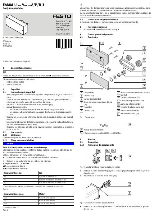
Traducción del manual original 1Documentos aplicablesTodos los documentos disponibles sobre el producto è/pk.Observar los documentos aplicables:–Instrucciones motor –Instrucciones eje2Seguridad 2.1Instrucciones de seguridad–Montar el producto solamente en aquellos componentes cuyo estado sea seguro.–Limpiar los ejes. El cubo de acoplamiento [17] solo se agarrará sin deslizamiento en un gorrón que esté seco y libre de grasa. –Respetar la alineación del cubo de acoplamiento [17].–Apoyar la combinación:–en caso de componentes de motor pesados o de gran saliente–en caso de vibraciones fuertes y cargas de choque y de masas excéntricas–Realizar un recorrido de referencia de los ejes después de soltar o de girar elmotor.–Seleccionar elementos de fijación necesarios. El conjunto incluye los elementos de fijación máximos necesarios.–Respetar los pares de apriete. Si no hay indicaciones especiales, la toleranciaes de ± 20 %.2.2Uso previsto 2.2.1UtilizaciónConexión en paralelo de un eje con un motor.2.2.2Ejes y motores admisiblesFallo funcional y daños materiales por sobrecarga.Las magnitudes de salida del motor no deben superar los valores admisibles de los componentes empleados.Valores admisibles è /catalogue.•Limitar en consecuencia las magnitudes de salida del motor.•Deducir el eje y el motor de los códigos de interfaz.Ejemplo: EAMMU...V2540P V25: acoplamiento de eje 40P : acoplamiento de motor Acoplamiento de ejeEje 1)V20EGSCBS25, EPCCBS25V25EGSCBS32, ELGCBS32, EPCCBS32V32EGSCBS45, ELGCBS45, EPCCBS451) Mini carro EGSCBS, eje de accionamiento por husillo ELGCBS, cilindro eléctrico EPCCBSTab. 1Acoplamiento de motorMotor 1)38AAMotor de otras marcas 40RMotor de otras marcas 40RAMotor de otras marcas1) Servomotor EMM...ASTab. 2La cualificación de los motores de otras marcas con acoplamiento mecánico apropiado utilizados en la combinación es responsabilidad del usuario.Su representante local de Festo le podrá indicar cuáles son los motores válidos de otras marcas è /sp.2.3Cualificación del personal técnicoEl montaje solo debe ser realizado por personal técnico cualificado. 3Información adicional–Accesorios è /catalogue.4Cuadro general del producto 4.1Suministro1Cuerpo (1x)2Tornillo (4x)5Correa dentada (1x)6Disco para correa dentada de eje (1x)7Tapa (1x)8Tornillo (3x)15Disco para correa dentada de motor (1x)16Tornillo prisionero (1x)17Cubo de acoplamiento (1x)18Anillo de retención (2x)19Estrella de elastómero (2x)20Anillo deslizante (2x)21Pasador roscado (3x)Fig. 1 Suministro30Manguito reductor (4x)Fig. 2 Complemento con EAMMU...40R/40RA 5Montaje 5.1Ensamblaje5.1.1Premontaje del acoplamientoFig. 3 Instalar anillo deslizante, lado del motor1.Instalar el anillo deslizante [20] en la ranura [K] del acoplamiento [17] del lado del motor.2.Desenroscar el tornillo prisionero [16].Fig. 4 Deslizar el cubo de acoplamiento •Insertar el cubo de acoplamiento [17] con el taladro apropiado en el gorrón del eje [C].8096444EAMM-U-...-V...-...A/P/R-3Conjunto paralelo8096444201901[8096447]Festo SE & Co. KG Ruiter Straße 82 73734 Esslingen Alemania+49 711 347Fig. 5 Alinear el cubo de acoplamiento1.Respetar la distancia (Y) .2.Apretar el tornillo prisionero del lado del motor [16].Fig. 6 Instalar anillo deslizante, lado del eje •Instalar el anillo deslizante [20] en la ranura [L] del cubo de acoplamiento del lado del eje [P].5.1.2Alineación de acoplamientoAlineación defectuosa del acoplamientoSi la dimensión Y está mal ajustada, se produce un mayor desgaste de la correa y puede provocar el contacto mecánico entre disco para correa dentada y cuerpo y tapa.•Respetar la distancia.Fig. 7 Alineación del cubo de acoplamiento EAMM-U-Y ±0,3[mm]45V2538AA 2645V2540R 25,545V2540RA 18,545V3238AA 2645V3240R 25,545V3240RA18,5Tab. 3 5.1.3Conexión motor y ejeFig. 8 Fijar el disco para correa dentada del lado del motor1.Insertar la estrella de elastómero [19], con el rebaje [M] mirando hacia el exterior, en el disco para correa dentada [15].2.Deslizar hasta el tope el disco para correa dentada [15] junto con la estrellade elastómero [19] en el cubo de acoplamiento [17].3.Insertar el anillo de retención [18] en la ranura [N] del cubo deacoplamiento [17].Fig. 9 Fijar el disco de correa dentada por el lado del eje1.Insertar la estrella de elastómero [19], con el rebaje [M] mirando hacia el exterior, en el disco para correa dentada [6].2.Deslizar hasta el tope el disco para correa dentada [6] junto con la estrella deelastómero [19] en el cubo de acoplamiento [P].3.Insertar el anillo de retención [18] en la ranura [C] del cubo deacoplamiento [P].Fig. 10 Fijar el cuerpo al eje1.Insertar el cuerpo [1] en el collar de centrado del ejeÄEl pasador antirrotación [O] del eje encaja en el taladro del cuerpo [1].2.Fijar el cuerpo [1] con los pasadores roscados [21] en la ranura en V del collarde centrado.Fig. 11 Posicionamiento del motor •Posicionar el motor en el cuerpo [1].ÄEl motor puede desplazarse y puede inclinarse fácilmente.Fig. 12 Colocar la correa dentada1.Desplazar el motor, hasta hacer tope, en el sentido del eje, e inclinar ligeramente.2.Colocar la correa dentada [5] primero en el disco para correa dentada [15] y,después, en el disco para correa dentada [6].Con el EAMMUV..40R/40RA se requieren los manguitos reductores [30].Fig. 13 Colocar el manguito reductor •Montar los manguitos reductores [30] en los orificios de fijación del motor.Fig. 14 Fijar el motor •Fijar el motor con los tornillos [2] al cuerpo [1].ÄEl motor puede desplazarse pero no se puede inclinar más.5.1.4Tensado de la correa dentadaExcesiva pretensión de la correa dentada.Cargas radiales inadmisibles o rotura del eje.Elevado desgaste de la correa dentada, así como de los cojinetes del eje y del motor.•Evítese una excesiva pretensión de la correa dentada.Se recomienda que la pretensión de la correa dentada sea reducida.La correa dentada [5] estará tensada cuando los ramales [D] discurran más o menos en paralelo:–Destensada: y > x–Tensada: y L1 … 1,05 xFig. 15 Ramales de la correa dentadaFig. 16 Tensar la correa dentada1.Desplazar el motor hasta que sobre la correa dentada [5] se ejerza la fuerzaelástica Fv.2.Apretar los tornillos [2].EAMM-UFuerza elástica Fv[N]305 ... 153817 (4045)17 (40)Tab. 4 Fuerza de tensión admisible de la correa dentada5.1.5Montaje de la tapaFig. 17 Montar la tapa •Antes de la puesta en funcionamiento: fijar la tapa [7] con los tornillos [8] al cuerpo [1].5.2Instalación 5.2.1Soporte de la combinación de eje y motorFig. 18 La combinación debe soportarse sin crear tensiones •Apoyar la combinación libre de tensiones para evitar daños.6Durante el funcionamiento Riesgo de lesiones al tocar superficies calientes.El juego de montaje del motor se calentará debido al calor generado por el motor.•No tocar el juego de montaje del motor durante el funcionamiento ni inmediatamente después.Riesgo de lesiones por movimiento inesperado de componentes en caso de fallo de la correa dentada.•Cumplir las medidas de seguridad complementarias.7Mantenimiento 7.1Comprobación de la correa dentadaLa correa dentada [5] es una pieza de desgaste è /spareparts. probar la correa dentada [5] periódicamente:–cuando se cumplen los plazos de mantenimiento de la máquina –cuando se sustituye un eje2.Sustituir la correa dentada [5] cuando aparezcan los siguientes indicios dedesgaste:–fuerte acumulación de partículas de desgaste en la carcasa –grietas en el dorso de la correa dentada–hilado de tracción de fibra de vidrio visible en la base de los dientes 7.2Sustitución de la correa dentadaFig. 19 Desmontar la correa dentadaEn caso de montaje en posición vertical o transversal:•Respetar las instrucciones de seguridad correspondientes incluidas en lasinstrucciones del eje.1.Retirar los tornillos [2].ÄEl motor puede desplazarse y puede inclinarse fácilmente.2.Desplazar el motor, hasta hacer tope, en el sentido del eje, e inclinar ligeramente.3.Retirar la correa dentada [5] de los discos para correa dentada [6] y [15].8Especificaciones técnicas8.1Tamaño de tornillos y pares de aprieteEAMM-U-[2] [Nm][8] [Nm][16][Nm][21][Nm] 45V2538AA M3x241,2M3x81,2M2,5x81M3x60,8 45V2540R M3x201,2M3x81,2M2,5x81M3x60,8 45V2540RA M3x161,2M3x81,2M2,5x81M3x60,8 45V3238AA M3x241,2M3x81,2M2,5x81M3x60,8 45V3240R M3x201,2M3x81,2M2,5x81M3x60,8 45V3240RA M3x161,2M3x81,2M2,5x81M3x60,8 Tab. 5。
山猫 7 吨电动液压木裂机 使用手册和安全说明书

KEEP GUARDS IN PLACE and in working order.KEEP WORK AREA CLEAN . Cluttered areas and benches invite accidents.DO NOT USE IN AN DANGEROUS ENVIRONMENT. Don’t use power tools in damp or wet locations, or expose them to rain. Keep work area well lit.KEEP CHILDREN AWAY. All visitors should be kept a safe distance from work area.DON’T FORCE TOOL. It will do the job better and safer at the rate for which it was designed.USE THE RIGHT TOOL . Don’t force tool or attachment to do a job for which it was not designed.WEAR PROPER APPAREL. Do not wear loose clothing, neckties, rings, bracelets, or other jewelry which may get caught in moving parts. Nonslip footwear is recommended. Tie long hair back.ALWAYS USE SAFETY GLASSES. Also use a face or dust mask if cutting operation is dusty. Everyday eyeglasses only have impact resistant lenses, they are NOT safety glasses.MAINTAIN TOOLS WITH CARE. Keep tools sharp and clean for best and safest performance. Follow instructions for lubricating and changing accessories.DISCONNECT TOOLS before servicing; when changing accessories, such as blades, bits, cutters, and the like.REDUCE THE RISK OF UNINTENTIONAL STARTING. Make sure switch is in off position before plugging in.USE RECOMMENDED ACCESSORIES. Consult the owner’s manual for recommended accessories.NEVER STAND ON TOOL. Serious injury can occur if the tool is tipped or if the cutting tool is unintentionally contacted.NEVER LEAVE TOOL RUNNING UNATTENDED. TURN POWER OFFDO NOT OPERATE WITH ANY GUARD THAT IS DISABLED, DAMAGED, OR REMOVED. Keep guards in place and in good working order.Wear ANSI-approved safety goggles under full face shield, heavy-duty work gloves and steel-toe work boots during use.Crushing hazard. Never place hands or feet between the log and splitter wedge or between the log and the ram during the forward or reverse stroke.DO NOT OVERREACH. Keep proper footing and balance at all times.GENERAL SAFETY WARNINGSRead all safety warnings and instructions. Failure to follow the warnings and instructions may result in electric shock, fire and/or serious injury. Save all warnings and instructions for future reference.The warnings, precautions, and instructions discussed in this instruction manual cannot cover all possible conditions and situations that may occur. It must be understood by the operator that common sense and caution are factors which cannot be built into this product, but must be supplied by the operator. Read carefully and understand all ASSEMBLY AND OPERATION INSTRUCTIONS before operating. Failure tofollow the safety rules and other basic safety precautions may result in serious personal injury.Never place hands or body near a hydraulic fluid leak or check for a leak with hands or other body parts. High-pressure fluid can be forced under the skin resulting in serious injury.Never split a log that contains any foreign materials such as nails for example.CHECK DAMAGED PARTS. Before further use of the tool, a guard or other part that is damaged should be carefully checked to determine that it will operate properly and perform its intended function check for alignment of moving parts, binding of moving parts, breakage of parts, mounting, and any other conditions that may affect its operation. A guard or other part that is damaged should be properly repaired or replaced. Do not use the splitter on logs longer than 20.5” or with a diameter greater than 10”.Hold the rounded, bark side of logs when loading or positioning, never the ends. Never place hands or any body parts between a log and any part of the log splitter.Never load or unload logs while the ram is moving.Do not attempt to split logs across the grain. Doing so will damage the log splitter and could cause pieces of log to be rojected outward, injuring the operator or bystanders.Never attempt to split more than one log at a time. A piece of log can unexpectedly be thrown from the machine, causing severe personal injury.Remove split logs away from the log splitter immediately. Split logs left near the log splitter are a tripping hazard.The use of accessories or attachments not recommended by the manufacturer may result in the risk of injury.Set up and operate only on a flat, level, dry and solid surface with wheels chocked.When servicing, use only identical replacement parts.Only use safety equipment that has been approved by an appropriate standards agency.Maintain labels and nameplates on the tool. These carry important safety information. If unreadable or missing, contact Stark Tools for a replacement.Avoid unintentional starting. Prepare to begin work before turning on the tool.People with pacemakers should consult their physician(s) before use. Electromagnetic fields in close proximity to heart pacemaker could cause pacemaker interference or pacemaker failure.DO NOT OPERATE WITH ANY GUARD DISABLED, DAMAGED, OR REMOVED. Keep guards in place and in good working order.WARNING: The cord of this product contains lead and/or di (2-ethylhexyl) phthalate (DEHP), chemicals known to the State of California to cause cancer, and birth defects or other reproductive harm. Wash hands after handling. (California Health & Safety Code § 25249.5, et seq.)WARNING: Some dust created by power sanding, sawing, grinding, drilling, and other construction activities, contains chemicals known to the State of California to cause cancer and birth defects orother reproductive harm. Some examples of these chemicals are:• Lead from lead-based paints• Crystalline silica from bricks and cement or other masonry products• Arsenic and chromium from chemically treated lumber Your risk from these exposures varies, depending on how often you do this type of work. To reduce your exposure to these chemicals: work in a well ventilated area, and work with approved safety equipment, such as those dust masks that are specially designed to filter out microscopic particles.(California Health & Safety Code § 25249.5, et seq.)NEVER use an extension cord longer than 25 feet. Minimum cord gauge must be 16, an undersized cord will cause a drop in line voltage resulting in a loss of power and overheating.ALWAYS use your hand to operate the control lever and the switch. NEVER use your foot or any extension device.NEVER modify the plug provided if it will not fit the outlet. Have the proper outlet installed by a qualified electrician.ALWAYS use a 3-wire extension cord with 3-prong grounded plugs and a 3-pole receptacles that accept this plugNEVER loosen or remove the hydraulic fitting or the cap of the hydraulic tank while the log splitter is running.NEVER operate your log splitter when it is in poor mechanical conditon or in need of repair.ALWAYS unplug the power cable before performing any maintenace and repair. Periodically check all nuts, bolts, screws hydraulic fittings and be sure the hose clamps are tightened.NEVER tamper with the motor to run it at excessive speeds. The maximum motor speed is preset by the manufacturer and is within safety limits.NEVER adjust the hydraulic valve. The system is preset at the factory and is within safety limits. ALWAYS check the level of hydraulic oil before operation.ALWAYS Repair or replace a damaged power cord immediately.NEVER check for leaks of hydraulic fluids with your hand. Fluid escaping from a small hole can be almost invisible. Escaping fluid under pressure can have sufficient force to penetrate skin, causing serious injury or even death. Leaks can be detected by passing a piece of cardboard over the suspected leak and looking for discoloration.ALWAYS seek medical attention immediately if injured by escaping hydraulic fluid. Serious infection or physical reaction can develop.ALWAYS be sure to relieve all pressure by shutting off the negine amd moving the valve control handle back anf forth should it become necessary to loosen or remove the hydraulic fitting.NEVER remove the cap from the hydraulic tank or reservoir while the log splitter is running. Hot oil under pressure could result in serious injury.NEVER adjust the hydraulic valve, the pressure relief valve on your log splitter is preset at the factory. Only a qualified service technicial should perform this adjustment.NEVER operate your log splitter near a flame or spark, hydraulic fluid is flammable and can explode. ALWAYS have a CLASS B fire extinguisher with you when operating this log splitter in dry areas as a pre-cautionary measure.NEVER move this log splitter while the motor is running.NEVER carry cargo or wood on your log splitter.SAVE THESE WARNINGSNOTE: This log splitter is assembled at the factory and has been pre-filled with hydraulic oil. Refer to the diagram below should it become necessary to disassemble the unit for repair or replacement of parts.NOTE: This machine is only intended for homeowners and non-commercial users to split firewood as detailed in the instructions and not for any other purpose.NOTE: Ensure the power supply is not conneted while preparing the log splitter for use.NOTE: If hydraulic fluid is difficult to obtain, Dextron automatic transmission fluid can be substituted. Use only clean oil and be sure to prevent dirt from entering the hydraulic reservoir. Do not mix AW32 hydraulic fluid with Dextron hydraulic flud. Log splitter is shipped with AW32 hydraulic fluid.IMPORTANT: Before operating the log splitter, turn the bleed screw two turns to allow air to be released from the hydraulic system. A flow of air through the bleed screw should be detectable while log splitter is in use. Close the bleed screw after operation. Make sure the bleed screw is closed before and during transport. Failure to loosen the bleed screw will cause pressure to build up in the hydraulic tankand could damage the seals and affect the operation of the log splitter.OPERATING THE DEVICEAlways wear safety glasses, gloves and shoes as well as suitable clothing when operating this log splitter. Never wear jewelry, or loose clothing and be sure to tie long hair back so as not to get tangled in moving parts.Keep hands and feet clear of the ram and wedge at all times.Keep away from flammable liquids and gases before starting the machine.1. Place the log splitter on a sturdy, level surface. Block the wheels to prevent movement of the log splitter during operation.2. Make sure the handle is free of oil, grease and resins.3. Oil the wedge and the top of the beam for smoother operation.4. Ensure the equipment is in safe working condition. Operate the unit without loading to make sure it is working normally. Check all nuts, bolts and hydraulic fittings are tight. Check the switch, power cable and plug for damage. Check all safety shields are in proper position.5. Check that the outlets main voltage and frequency match the data stated in the model plate or technical specifications in this manual.6. Plug in the power cable and switch on the motor. NEVER use an extension cord longer than 25 feet. The power supply to this log splitter must have a protection device (circuit breaker) for over or under voltage.7. Place a log on the beam against the push plate. Make sure the log is securely on the beam and up against the push plate. Logs should be cut with square ends and to a maximum length of 20” in advance. Always use extra care when splitting logs with unsquare ends.8. Two controls must be activated to operate the log splitter. The hydraulic control lever and the On/Off push button must be held during the splitting process. If either control is released, the log splitter will stop working.9. Loosen the bleed screw one or two turns if necessary.10. Depress and hold the On/Off push button with your right hand and allow the motor to cycle up to speed.11. Push down the hydraulic control lever;12. Release the On/Off button and the control lever when the log is split, the push log will then retract. REPLACING HYDRAULIC FLUIDNote : Change hydraulic fluid after every 100 hours of use.Note : Be sure to unplug the power cord before replacing hydralic fluid.1. Place a large pan under the motor end of the log splitter.2. Use the included hex wrench to loosen the fluid drain bolt and remove the bolt with the attached dipstick.3. Raise the splitting wedge end of the log splitter to allow the fluid to drain into the pan. Lower the splitter when it is empty.4. Dispose of the old hydraulic fluid in accordance with local regulations.5. Raise the motor end of the splitter and make sure it is secure.6. Pour approximately 3.2 liters of hydraulic fluid into the tank.7. Check the fluid level of the dipstick, add more fluid of needed.8. Replace the fluid drain bolt and tighten securely.9. Lower the log splitter.Allow the log splitter to cool down for five minutes before storing.Switch off and unplug the log splitter before storing.Protect the power supply cable from heat, sunlight, agressive liquids and sharp edges.Store the unit in a clean, dry area. Do not store outdoors or next to corrosive materials or in a damp environment.Store the log splitter out of reach of children.STORING THE LOG SPLITTERTROUBLESHOOTING1. Switch off the power and unplug the log splitter.2. Always check the hydraulic oil leve before operation. Operating the log splitter without adequate hydraulic oil can cause damage to the log splitter.3. Wipe the unit after each use with an oil rag to prevent rust.4. The hydraulic system is preset at the factory. Do not adjust the valve.5. If the ram moves slowly or erractically, there may be air in the system or insufficient oil. Check the level of hydraulic oil with the dipstick.6. For other hydraulic and motor problems not addressed in this manual, contact a qualified technician.7. If the wedge is dull or nicked, sharpen it. Always wear safety glove while handling the wedge8. All replacements parts must meet the manufacturers specifications.Note : If the motor is overloaded for a long time, the thermal protector will disconnect the power of the the motor. Switch off and unplug the power cord to cool down the motor for 30 minutes. Restart the motor and the log splitter should operate again.Note : Switch off and unplug the power cable quickly if the machine is acting abnormal.TECHNICAL SPECIFICATIONSTROUBLESHOOTINGOF NOTEPLEASE READ THE FOLLOWING CAREFULLYTHE MANUFACTURER AND/OR DISTRIBUTOR HAS PROVIDED THE PARTS LIST AND ASSEMBLY DIAGRAM IN THIS MANUAL AS A REFERENCE TOOL ONLY. NEITHER THE MANUFACTURER OR DISTRIBUTOR MAKES ANY REPRESENTATION OR WARRANTY OF ANY KIND TO THE BUYER THAT HE OR SHE IS QUALIFIED TO MAKE ANY REPAIRS TO THE PRODUCT, OR THAT HE OR SHE IS QUALIFIED TO REPLACE ANY PARTS OF THE PRODUCT. IN FACT, THE MANUFACTURER AND/OR DISTRIBUTOR EXPRESSLY STATES THAT ALL REPAIRS AND PARTS REPLACEMENTS SHOULD BE UNDERTAKEN BY CERTIFIED AND LICENSED TECHNICIANS, AND NOT BY THE BUYER. THE BUYER ASSUMES ALL RISK AND LIABILITY ARISING OUT OF HIS OR HER REPAIRS TO THE ORIGINAL PRODUCT OR REPLACEMENT PARTS THERETO, OR ARISING OUT OF HIS OR HER INSTALLATION OF REPLACEMENT PARTS THERETO.Record Product’s Serial Number Here:Note: If product has no serial number, record month and year of purchase instead.Note: Some parts are listed and shown for illustration purposes only and are not available individually as replacement parts.PRODUCT MADE IN CHINA10。
伊顿液压拖拉机应用手册说明书

伊顿液压拖拉机应用手册伊顿流体动力( 上海) 有限公司,总部位于外高桥保税区内,在外高桥及康桥工业区设有工厂,在全国设有20 个销售办事处。
公司致力于液压系统与零部件的设计、组装生产及测试和销售服务,以世界级的产品质量和服务扩大中国市场。
公司现已经建立了完善的仓储物流一生产制造一技术支持一客户服务体系,为客户提供完备的供货、定制生产、技术选型、培训、售后服务和外币结算服务。
另外,公司作为伊顿大中华区乃至亚太区的服务及维修中心,为客户提供完善的售后服务。
成立于1994 年,2002 年完成独资,现位于济宁市开发区伊顿工业园区(伊顿在中国建立的第一个工业园),主要生产液压马达、液压转向器、液压阀、柱塞泵、扭矩发生器。
公司拥有KAPP 、BLOHM 等世界一流水平的磨床、先进的CNC 加工中心、可靠和高精度检验试验设备,于1997年通过ISO9001质量体系认证,是伊顿公司核心产品和零部件的生产基地,为世界知名厂商提供高质量的产品和服务,满足伊顿全球客户的需求。
伊顿液压(泸州)有限公司是伊顿全资拥有的外商独资企业。
公司位于四川泸州经济技术开发区,是国内优秀的液压管路整体方案的提供者之一。
公司产品主要涵盖:液压胶管接头、过渡接头、胶管总成、钢管总成及不锈钢液压管路连接件。
公司拥有大批国内外先进的MAZAK 、Kitako 等先进数控车床、拥有先进的无氰镀锌生产线,镀锌质量达到国内外先进水平,拥有进口FINNPOWER 扣压机和试压设备组成总成装配生产、检测线。
并通过了ISO9000,ISO14000等国际体系认证,产品销往北美,澳大利亚,新加坡等海外客户以及国内工程机械,海洋钻井平台,风电,冶金等行业。
2005 年4 月,伊顿(中国)投资有限公司整体收购了宁波永华液压器材有限公司,成立了伊顿液压(宁波)有限公司,公司位于宁波市高新技术产业开发区。
公司有一大批先进的CNC 自动送料和加工的机床、接头装配的自动加工流水线、进口FINNPOWER 软管总成扣压设备和进口TRANSFLUID 硬管弯管设备。
NEMCO 食品设备 MONSTER AIRMATIC 操作和维护指南说明书

Operating and Maintenance Instructions 56455- ( ) MONSTER AIRMATIC56455-( ) Operating and Maintenance InstructionsNEMCO FOOD EQUIPMENT 301 Meuse Argonne, Hicksville, OH 43526Phone: (419) 542-7751 Fax: (419) 542-6690 Toll free: 1-800-782-6761FAILURE TO FOLLOW SAFETY INSTRUCTIONSCOULD RESULT IN SERIOUS PERSONAL INJURYCAUTION: THIS POWER UNIT CAN BE DANGEROUS! THIS UNIT CAN CAUSE SERIOUS INJURY OR BLINDNESS TO THE OPERATOR AND OTHERS. THE WARNINGS AND SAFETY INSTRUCTIONS IN THIS MANUAL MUST BE FOLLOWED TO PROVIDE REASONABLE SAFETY AND EFFICIENCY IN USING THIS UNIT. THE OPERATOR IS RESPONSIBLE FOR FOLLOWING THE WARNINGS AND INSTRUCTIONS IN THIS MANUAL AND ON THE UNIT. READ THE ENTIRE OPERATOR’S MANUAL BEFORE USING THE UNIT. THE USE OF THIS UNIT SHOULD BE RESTRICTED TO PERSONS WHO HAVE READ, UNDERSTAND, AND FOLLOW THE WARNINGS AND INSTRUCTIONS IN THIS MANUAL AND ON THE UNIT. NEVER ALLOW CHILDREN TO OPERATE THE UNIT.CAUTION AND WARNING DECALS LOCATED ON THIS UNIT:56455-( ) Operating and Maintenance InstructionsNEMCO FOOD EQUIPMENT 301 Meuse Argonne, Hicksville, OH 43526Phone: (419) 542-7751 Fax: (419) 542-6690 Toll free: 1-800-782-6761IMPORTANTCLEAN MACHINE THOROUGHLY BEFORE USING IT FOR THE FIRST TIME1.To get the best operation and life from your machine, please read and comply with these instructions. 2. Clean machine thoroughly after each use using cleaning instructions below.3.Minimize the use of alkaline cleaners as they may cause pitting and dulling of the finish.SAFETY INSTRUCTIONSFAILURE TO FOLLOW SAFETY INSTRUCTIONS COULD RESULT IN SERIOUS PERSONAL INJURY1. Remember that the blades are VERY SHARP! Be careful when handling and operating the machine to keep handsaway from the BLADES.2. NEVER Grasp exposed cutting blades or cutting edges when picking up or holding the unit.3. Inspect unit before operation for loose or damaged parts. Do not use the unit unless it is in proper working order.4. Never operate unit without plastic cover in place.5. This unit is designed for operation by ONE (1) Person ONLY.CAUTION: ALWAYS DISCONNECT AIR HOSE FROM CUTTER WHEN TRANSPORTING, CLEANING,INSTALLING, OR SERVICING.INSTALLATION1. Install Air Compressor according to manufacturers guidelines.(Compressor Not Provided with Unit) Suggested size is 1.5 HP to 2HP with minimum SCFM of 5.6 at 90psi.2. Connect air hose to air compressor. Use a 3/8” minimum int ernal diameter hose. Refer to Compressor Manual for necessary size fittings.3. Connect air hose to cutting machine using quick disconnect fitting provided. Connect to “AIR CONNECTION” fitting on mounting bracket.4. The FryKutter is to be mounted in a horizontal fashion. It comes equipped with suction cups for attachment to a stainless steel prep table.5.If unit fails to operate properly when first used call NEMCO customer service at 1-800-782-6761.Note: Air compressor should be equipped with a Particulate Filter capable of filtering 50 µm, a Coalescent Filter to remove water and oil, and a Pressure Regulator. The filters should be installed in the air supply line within 8 ft of the unit. Theregulator should be set at 80psi minimum, 100psi maximum. Failure to install the compressed air conditioning equipment will void the warranty.OPERATION OF FryKutter1. With the COVER in the fully opened position, lay the prepared produce in the trough.2. Remove hands and fingers from the cutting area.3. Move COVER to fully closed position. The machine will cycle, cutting the produce. Occasionally if the produce is very large, or if it is positioned at an angle to the blades, this may have to be repeated to cut it entirely through. CAUTION: Do not attempt to chop produce larger than the opening in the BLADE HOLDER.4. Push block will “Return” to back of cutter when COVER is moved to fully opened position.5.Clean the machine after cutting is completed, using cleaning instructions below.TO CLEAN THE FryKutter1. Always thoroughly was the vegetable cutter after every use. The PLASTIC GUARD, PUSH BLOCK, BLADE AND HOLDER ASSEMBLY, AND CYLINDER are removable for easier cleaning. Always use warm water and mild detergent.2. Wash the vegetable trough on the FRAME CASTING after each use.3. Always thoroughly wash the PUSH BLOCK and the BLADE AND HOLDER ASSEMBLY.4. Release the PUSH BLOCK by turning the THUMB SCREWS located on the PUSH BLOCK GUIDE in a counter clockwise motion until the PUSH BLOCK is loose.5. To reassemble the PUSH BLOCK hold it up against the PUSH BLOCK GUIDE and fasten it by turning the THUMB SCREWS.6. To remove the blade assembly, unscrew the GUIDE RODS while holding the WING NUTS. Pull back on the GUIDE RODS and carefully remove the BLADE AND HOLDER ASSEMBLY.7.To reattach the BLADE AND HOLDER ASSEMBLY, hold the BLADE AND HOLDER ASSEMBLY tight to the bottom of the FRAME. Completely tighten both GUIDE RODS and WING NUTS so the BLADE AND HOLDER ASSEMBLY is held tightly against the bottom of the FRAME.TO LUBRICATE1.When necessary, lubricate GUIDE RODS and PINS at each joint with Mineral Oil or Food Grade Grease.56455-( ) Operating and Maintenance InstructionsNEMCO FOOD EQUIPMENT 301 Meuse Argonne, Hicksville, OH 43526Phone: (419) 542-7751 Fax: (419) 542-6690 Toll free: 1-800-782-67612. DO NOT LUBRICATE WITH COOKING OIL – IT GETS STICKY.3.DO NOT LUBRICATE CYLINDER ROD-IT IS SELF LUBRICATING INTERNAL TO THE CYLINDER.56455-( ) SERVICE PARTS:56222-1, PUSH BLOCK GUIDE ASSEMBLY INCLUDES(2) 56203, BUSHINGS(1) 56222, PUSH BLOCK GUIDEBLADE ASSEMBLY, SLICE & CHOP 56424-1T , 1/4” CHOP DOUBLE TIER 56424-1, 1/4” CHOP SINGLE TIER56424-2, 3/8” CHOP 56424-3, 1/2” CHOP 56424-5, 1/4” SLICE 56424-6, 3/8” SLI CENOTE: ALL BLADE ASSEMBLIES OTHER THAN 56424-1T ARE FASTENED TO MACHINE USING (2) 45058 WINGNUTS.。
千斤顶用户手册说明书

15
Only skilled staff may operate a mechanical jack.
16
Before use this manual has to been read and understood. When there are any questions left you should contact an expert (for
USER MANUAL MECHANICAL JACK
HANDELMAATSCHAPPIJ VLIERODAM B.V. NIJVERHEIDSWEG 21 POSTBUS 827 3160 AA RHOON 010 - 5018000 010 – 5013843 www.vlierodam.nl
USER MANUAL MECHANICAL JACK
6
Neve apply to heavier loads than indicated on the type of plate.
7
Never use the mechanical jack when it is in bad shape.
8
Never use the mechanical jack without a solid and flat surface.
3
It is not allowed to lift any persons with a mechanical jack.
4
The mechanical jack is for manual use only. Mechanical transmission is not allowed.
5
The brake discs of het mechanical jack may not come in contact with any grease or moisture. THE BRAKE WORKS DRY.
- 1、下载文档前请自行甄别文档内容的完整性,平台不提供额外的编辑、内容补充、找答案等附加服务。
- 2、"仅部分预览"的文档,不可在线预览部分如存在完整性等问题,可反馈申请退款(可完整预览的文档不适用该条件!)。
- 3、如文档侵犯您的权益,请联系客服反馈,我们会尽快为您处理(人工客服工作时间:9:00-18:30)。
1LF-5高速调幅液压翻转犁 用户使用手册
Cod. EOV0004OS 2011- 04 概 述 本手册包含大犁产品的使用和保养说明及所供备件。 “大犁”作为农机具,通过提升装置和通用3点悬挂与拖拉机挂接后用于土地耕作。 正确和良好的操作有助于提高产品的经济性和使用寿命。因此我们建议严格按照以下说明操作,以防止可能会导致产品故障及影响产品使用寿命的错误发生。
遵守手册中的指示要求很重要,制造商将不承担任何若因疏忽或未遵守这些指示说明而导致全部和单项责任。
但为确保机器的正确操作及最大作业效率,制造商将根据客户的需求提供及时全面的服务及其它事宜。制造商有权对机器进行任何可能认为是适当的的修改和改进,而毋须立即通知用户。 目 录 1. 安全条款 2. 产品说明和技术参数 3. 犁间距调整 4. 保护系统 5. 作业设置 5.1. 犁壁 5.2. 与拖拉机挂接 5.3. 轴线/调直 5.4. 前犁沟宽度 5.5. 其它调整 6. 犁深 7. 运输和驻车 8. 维修保养 9. 选装件 10.易损件清单 1. 安全条款 • 全面完整地阅读和熟悉 “大犁”的使用说明。 • 若因未遵守下面所提及的安全和事故预防规则而产生的后果,生产商将不承担任何全部和单项责任。
1.1 遵守手册中和贴在“大犁”机器上的危险标识的指示说明(图1)。 1.2 机器的任何维护和调整只有在拖拉机关闭发动机且制动后才可进行。 1.3 绝对禁止用本机器运送人员和牲畜。 1.4 绝对禁止无驾照或驾车不熟练人员以及那些健康状况不稳定人员来驾驶挂接本机器的拖拉机。
1.5 严格遵守本手册建议的事故预防措施。 1.6 机器挂接到拖拉机后会改变拖拉机前后桥的重量分配。 1.7 在启动拖拉机和本机器前,必须检查运输和工作安全防护装置处于正确状态。 1.8 贴在机器上的指示标签就如何预防事故提供了有效建议。 1.9 在公路运输时,严格遵守当地的交通法规。 1.10遵守拖拉机的最大允许轴重、最大允许载重(总可调重量),运输规则和道路法规。 1.11在作业前一定要熟悉机器的控制和操作。 1.12在机器挂接和分离时要万分小心。 1.13在拖拉机移动时绝对不能离开驾驶座椅。 1.14 谨记:当拖拉机挂接机器时/后,其车辆行驶控制、转向和制动的能力可能会受到明显的影响。
1.15绝对禁止任何人站在机器的作业范围内。 1.16离开拖拉机前,请将机器降落到地面,关闭发动机,接合手制动并拔下点火钥匙。 1.17机器的挂接销子类型必须与提升悬挂装置的类型一致。 1.18在挂接点附近工作时要特别小心。这是一个比较危险的区域。 1.19从外面操作液压提升控制时,绝对禁止人站在大犁和拖拉机之间。 1.20挂接着大犁在道路上运输时,将液压提升控制杆置于锁定位置。 1.21备件必须符合制造商的要求,建议使用原厂配件。
1.22安全标识必须清晰可见。必须保持标识清洁,如果变得难以辨认必须更换。根据要求可以从当地经销商处获得这些更换品。
1.23本说明书必须妥善保管到机器报废。
警告! 使用前请认真阅读本使用手册。 危险!不要在设备悬挂离地时维护设备,请保持必要的安全距离。 机器翻转时容易造成人员伤亡,请保持必要的安全距离。 (图1)
紧急情况的准备 附近应有急救箱和灭火器(图2)。写下医院、急救车、消防的电话号码并置于身旁。
着装合适 避免穿着肥大的衣服并根据实际作业情况佩戴合适的保护装置(图3)。机器的安全操作需要操作员全方面的细心。 操作本机器时不要戴耳机听收音机。
图2 图3
2. 产品结构和技术参数 产品结构(图4) 图4 2.1 犁头 2.2产品标牌 2.3液压翻转装置 2.4挂接架 2.5犁尖 2.6犁铧 2.7刮板 2.8犁壁 2.9限深轮 2.10犁侧板 2.11大梁 2.12犁柱
技术参数 项目 犁架高度 1LF-3 1LF-4 1LF-5 犁铧间距调整范围 (厘米) 850毫米/950毫米 33-38-44-50 33-38-44-50 33-38-44-50
配套动力( 马力 ) 850毫米/950毫米 120-150 150-180 180-220 整机重量( 千克 ) 850毫米/950毫米 830 1035 1410 外形尺寸(毫米) 5700×1800×1800 3.调整 1LF系列大犁,可以通过人工调节,每5厘米为一个级别。通过1-4级别的调整,达到最大和最耕幅的目的。
4.安全保护系统 1LF系列大犁的安全保护是通过剪切螺栓实现的(图5)。犁尖遇到障碍时,剪切螺栓剪断,犁柱顺力的方向转动,有效保护大犁和拖拉机安全。将大犁提升到一定程度,将犁柱恢复到初始位置,更换符合标准的剪切螺栓,即可重新工作。 图5
5.作业调整 5.1 犁壁 工作前,先将犁壁上的油漆刮掉,避免土壤粘结在犁壁上,并增加阻力。 调整各间距,如图6所示,A1=A2,B1=B2,如果此间距有差异,请调整螺母D,调整拉杆C的长度(图7)。
图6 图7 5.2 与拖拉机挂接 OVLAC大犁可与任何的三点悬挂拖拉机配套。 挂接部分可以有两种标准长度 (中心到中心距离): II类悬挂 900毫米 III类悬挂 1000毫米 挂接点受力交叉点必须位于拖拉机前桥的中间位置,如图8所示。 图8
5.3 调平 大犁应该始终保持和拖拉机保持一条直线上。否则,拖拉机将偏离作业线路。检查长度,确保A1=A2(图7)。OVLAC 大犁可实现自动对正功能,得益于其横向可调挂接架。带有定挂接架的,可通过调整螺栓来校正(可选装液压校正)。
第三点挂接必须连接,并确保犁端连接点比拖拉机端连接点略高(图9)。 第三点挂接应始终挂在狭长孔上,确保工作时不相干涉。 图9 5.4 前犁宽度 通过图10中螺杆C调整第一个犁体的侧向位置,标准如图12。 图10
图12 错误 正确 5.5 其他调整 拖拉机上拉杆长度调整必须保证大犁大梁与地面平行,否则,将出现耕深不一致的现象,影响作业效果(图13)。 图13
正确 错误 如果出现耕深不一致,还应检查犁柱是否垂直于地面(图14)。首先应保证拖拉机左右提升臂高度一致,调整犁头上的螺栓A(图15)
正确 错误
图15 6.大犁工作深度 大犁的工作深度由拖拉机的液压控制杆进行调整。但是所有的大犁都带有一限深轮,限深轮的高度可以通过螺栓进行调整。
为了达到最佳的工作效果,请参照下表中工作深度和犁沟宽度相互关联。
犁沟宽度(厘米) 33 38 44 50 最大深度(厘米) 24 28 32 36 最小深度(厘米) 15 17 20 22 推荐深度(厘米) 21 25 28 32 7.运输和停放 为了保证安全、方便的运输,大犁通过宽度控制系统调整到最小幅宽状态。对于4-5铧犁,可配有多功能轮胎(图16),用于深度控制和运输。
停放时,支架可以保证大犁平稳。大犁工作时,必须收起支架(图17)。 图16 图17 8.保养 工作第一个8小时后,紧固所有的螺栓和螺母,特别是犁壁、犁铧和犁尖。此后,每100小时进行检查。当设备停放前,进行犁壁清理和涂油,防止犁壁生锈。
安全保养 进行保养前,熟悉所有的保养步骤。保养区域必须清洁干燥。进行保养、维修、调试时,拖拉机发动机一定要保持关闭。手、脚、衣服等一定要远离运动部件。关闭所有的控制。所有的部件一定要状态良好,并保证正确的安装。如果发现任何损坏,立即修理。更换所有磨损超限或者损坏零件。保证所有部件清洁干净。如果在设备上进行焊接,要断掉所有与拖拉机相关连接。
小心高压泄露 管路中液压油带有很高的压力,可以穿透皮肤, 图18 引起严重的伤害(图18)。因此,在断开管路前, 确保证压力完全释放。在使用液压系统前,确保所 有的连接和液压管路连接良好。如果要检查液压泄 露点,用一块纸板放在泄露处。不要用手或者身体 的任何部位检查高压泄露点。一旦任何事故发生, 立即去看医生。
液压管路的存放 保证液压接头清洁干净。任何磨损性颗粒,例如沙子或金属碎屑,都会损坏油封和油缸,进而引起液压泄露或其它故障。 9.选配部件(图19) A 覆土板 B 草刮板 C 玉米刮板 D 犁刀 图19
10. 易损件清单 序号 零件号 描述 备注 1 64000033 犁尖 2 63000073 翻转轴前轴承 3 63000074 翻转轴后轴承 4 64000102 圆盘犁片 5 63000029 圆盘犁片轴承 6 95009931 翻转轴后轴承垫片 使用马斯奇奥原厂配件 高品质的保证 选用润滑油应符合API GL-5或MIL-L-2105C标准 选用润滑脂应符合DIN 51825(KP2K)标准
MASCHIO GASPARDO S.p.A. 马斯奇奥(青岛)青岛农业机械有限公司 Sede legale e stabilimento produttivo Campodarsego (PD) 青岛经济技术开发区富源工业园5号路南 Via Marcello, 73 – 35011 Campodarsego (Padova) – Italy 电话:+86 532-86918691 Tel. +39 049 9289810 – Fax +39 049 9289900 传真:+86 532-86918690 Email:****************www.maschionet.com