ADAM-5510系列产品快速入门手册
adam4080快速入门手册
ADAM-4080/4080D 快速入门手册第一章ADAM-4080/4080D的安装1.1 概述ADAM-4000系列模块是一种模块内置式微控制器,传感器到计算机接口的智能设备。
这些模块通过发出ASCII码格式的简单命令集并以RS-485通讯协议发送予以遥控。
本模块提供信号调理、隔离、调整量程、A/D转换、数据比较及数据通讯功能。
! 软件配置和校准ADAM-4000模块无需设置电位器和开关。
仅从主机发出命令就能改变模拟量输入模块各种量程的电压输入。
全部模块的配置参数,包括I/O地址、速度、奇偶位、上限报警、下限报警、校准参数等均可以远程设定。
借助研华公司提供的菜单式软件、安装命令或校准命令实现远程设定。
配置参数和校准参数存入EEPROM存储器,在掉电情况下也能保存这些参数。
! 电源要求ADAM模块以非稳压的工业标准十24V直流电源供电,但也接受变化范围在十10V至十30V之间的任何直流电源。
电源纹波峰峰值必须在5V以内,瞬态纹波应保持在十10V至十30V之间。
! 连接和编程ADAM模块能连接到所有计算机和终端上并与之通讯。
它们采用RS-485传输标准,并用ASCII 格式通讯。
每一个型号模块的命令集由近10条指令组成。
模块和模块之间的通讯都以ASCII码实现,这就意味着ADAM模块能以任何高级语言编程。
! RS-485网络RS-485网络提供较低噪声传感器读入。
由于模块很靠近信号源,通过采用 ADAM RS-485中继器,可以将多达256个ADAM模块连接到RS-485网络上,将最大通讯距离延伸到1200m。
主机通过 ADAM RS-232/RS-485转换器用一个 COM通讯口连到 RS-485网络。
为了提高网络的吞吐能力,ADAM RS-485中继器采用逻辑 RTS信号管理中继器的方向。
RS-485网络仅需两根线:DATA十和 DATA一。
通过低廉的屏蔽双绞线连接。
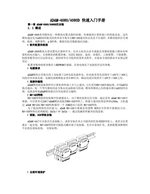
! 面板、DIN导轨安装ADAM-4017可安装在任意面板上,或者安装在本公司提供的托架或DIN导轨上,或者分层重叠在一起安装。
ADAM-4118快速入门手册

ADAM-4118快速入门手册ADAM-4118快速入门手册一、ADAM-4118概述ADAM-4118是16位A/D、8通道的热电偶输入模块,可以采集电压、电流热电偶等模拟量输入信号,它支持多种热电偶类型(Type J, K, T, E, R, S, B),并且将测量到的温度以工程量单位(℃)输出给上位机。
为了适应各种应用场合,ADAM-4118的每个通道可以配置成不同的热电偶输入类型。
ADAM-4118支持8路差分信号,还支持MODBUS协议。
在模块的右侧有一个白色的拨码开关来设置初始化状态(INIT*)和正常工作状态的切换。
除了热电偶量程外,ADAM-4118还具有4-20ma、±20ma等电流量程,当需要测量电流时,不需要外接电阻,只需打开盒盖,按照电路板上的标识来设置跳线即可。
ADAM-4118规格说明AI 模拟量输入● 有效分辨率:16位● 通道:8路差分,可独立设置量程● 高共模电压:200Vdc● 通讯协议:ASCII 命令,Modbus 协议● 输入类型 & 量程范围50mV , ±100mV , ±500mV , ±1V , ±2.5V电流模式±20 mA, +4~20 mA●隔离电压:3000VDC ● 过压保护:±60V● 采样速率:10/100 采样点每秒(通过测试软件设置)● 输入内阻:电压20M Ω,电流120Ω● 精确度:电压模式:±0.1% or better 电流模式& 高速模式:±0.2% or better ● 零点漂移:±6μV /℃● 跨度漂移:±25 ppm/° C● 共模抑制(CMR )@50/60Hz dB min● 内置看门狗● 内置 TVS/ESD 保护● 功耗 1.2W@24VDC跳线设置:ADAM-4118测量电流时需要跳线。
ADAM-4060(4068)快速入门手册
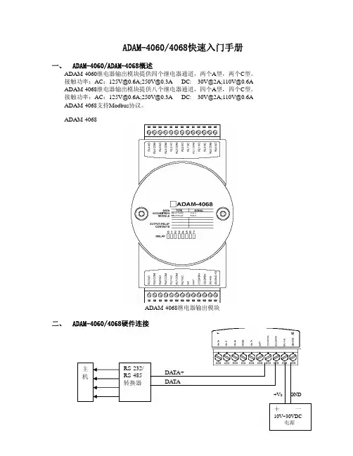
ADAM-4060/4068快速入门手册一、 ADAM-4060/ADAM-4068概述ADAM-4060继电器输出模块提供四个继电器通道,两个A 型,两个C 型。
接触功率:AC :125V@0.6A;250V@0.3A DC: 30V@2A;110V@0.6A ADAM-4068继电器输出模块提供八个继电器通道,四个A 型,四个C 型。
接触功率:AC :125V@0.6A;250V@0.3A DC: 30V@2A;110V@0.6A ADAM-4068支持Modbus 协议。
ADAM-4068ADAM-4068继电器输出模块二、ADAM-4060/4068硬件连接1.ADAM-4068模块简单控制接线图ADAM-4060 A型继电器的输出ADAM-4060 C型继电器的输出ADAM-4068 A型继电器的输出ADAM-4068 C型继电器的输出三、ADAM-4000 Utility的使用1. ADAM-4000的应用软件-ADAM Utility 的安装把ADAM4000 随机附带光盘放入计算机的光驱中,出现如下画面选择ADAM4000 Utility 安装选项,出现如下安装界面:根据后续的软件安装提示,完成ADAM4000 Utility 的安装。
PC机上就会出现ADAM4000 Utility的软件如下图2 .ADAM Utility的快速使用1. 选中COM1或COM2,点击工具栏快捷键search:网络扫描如下图所示3. 点击模块,进入测试/配置界面:4. 终端(Terminal)在TOOL菜单,选择Terminal功能,弹出一个【Terminal】对话框,可以测试模块的命令。
本选择允许在RS-485总线上直接发送和接受命令。
有两个可选项,Single Command,Command File。
Single Command允许将命令键入,一次一个,并击ENTER键,命令的回答显示在下方空白区内。
基于组态王和ADAM5510的分布式监控系统

王, 采用研华的 A D A M5510 可编程控制器进行现场数据的采集。该系统实现了对过程控制装置的温度、 压力、 流量、 液位等四大热工 参数的实时数据采集和装置锅炉温度、 锅炉液位的实时控制。该系统具有一定的实用性。 关键词:组态王 监控系统 中图分类号:T P311 .1 分布式 过程控制 文献标识码:A
� � � A � � � � � � � � : � K � � � � � � � � � � � � � A � D � � A� M5510 � � � � � � � � � � � � � � � � � � � � � � � � � � � � .M � � � � � � � � � � � � � � � � � � � � � � � K � � � � � � � � � � � A D A M55 10 PC PLC A . � � � P � � � � � � � � � � -� � � � � � � � � � � � � � � � � � � � � � � � � � � � � � � � � � � � � � � � � , , , � � � � � � � � � � � � -� � � � � � � � � � � � � � � � � � � � � � � , . :K M D P
装置的温度、 压力、 流量、 液位等 多个 I/ O 点 的数据 进 行实时采集和监控。其中上位采用装有组态王的工控 机, 下位采用研华科技 的 A D A M5510 分布式 数据采 集 控制器。系统结构如图 1 所示。本系统充分利用 了组 态王较好的 人机 界 面功 能和 A D A M5510 稳 定可 靠 的 特点来实现了一个小 型的分 布式 监控系 统。同时, 本 系统采用的模块化结构可以对检测和控制的 I/ O 数很 容易地进行扩展, 其扩展 功能支 持的监 控点 数可达 数 千个点之多, 能够满足实 际工业 生产过 程监 控系统 的 扩展需要; 同时 A D A M 5510 带 有一个 R S48 5 接口和 一 个 R S232 接口, 可以很方便地 与监控 系统的 其他设 备 进行相互连接和通信。
快速入门指南.pdf_1701221861.9791818说明书

Quick start guide for p5510(9110-51A)IBMSystems1Before you beginThis Quick start guide contains an abbreviated set of setup instructions designed to help you quickly unpack and set up a standard system.Users unfamiliar with this IBM hardware should use the fully detailed,setup instructions that you can find in the IBM Systems Hardware Information Center.For details about how to access the information center,see task 9.Finish your system setup CAUTION:The weight for this part or unit is between 18 and 32 kg (39.7 and70.5 lbs).It takes two persons to safely lift this part or unit.(C009)The exclamation mark surrounded by a gray triangle denotes caution.A CAUTION notice indicates the presence of a hazard that has the potential of causingmoderate or minor personal injury .Before doing a step that contains a caution icon,read and understand the caution statement that accompanies it.Use safe practices when lifting.Rack-mounted devices are not to be used as a shelf or workspace.Do notplace any object on top of rack-mounted devices.Inventory 22.1Complete an inventory of the external parts.Locate the kitting report (inventory list) in the bag that contains the informationcenter CD (SK3T -8159).Make sure you received all of the parts that you ordered.Y our order information should be located in an envelope adhered to the outsideof your system box.Y ou can also obtain order information from your marketingrepresentative or IBM Business Partner.If you have incorrect,missing,or damaged parts,consult any of the followingresources:Y our IBM resellerIBM Rochester manufacturing automated informationline at 1-800-300-8751(United States only)Directory of worldwide contacts at /planetwide.Select your location to view the service and support contact information.2.2Y ou will need the following parts:Cable-management arm Rack-mounting hardware kitScrews233.1 3.2 3.3If you are installing your server into a new rack,ensure that you have completed the unpacking instructions that were provided with the rack.If your s is already installed in a rack,skip to task 7Place the rack in the location of the installation.Use the wrench that was provided with your rack to level the rack by raising or lowering the front and back leveling feet.Install the stabilizer bracket on the front of the rack.If necessary,remove any trim kit pieces that were previously installed on the rack.Removing the trim kit pieces allows you to read the EIA units on the rack.ABTip:erver Cable the HMC and the server.3.4Prepare the rack for installationAB4.1Determine where in the rack to place the server.This server occupies two EIA units.Remove any filler panels necessary to allow adequate access to the location whereyou will install your server.If you do not have enough space around your rack to open the front and back doors completely,remove the doors before starting this task to allow adequate access.Install the slide rail assemblies 44.2Install the slide rail assemblies.Pull the front and back blue latch-assembly release tabs and use the bluetabs to push the latch assembly into the retracted position.Make sure bothfront and back slide-rail pins are fully retracted.B C D A 1.Front viewNote:Install units into the lower part of the rack first.Place larger and heavierunits in the lower part of the rack.4.34.4()Optional Finger-tighten the system-retaining screws into the backslide-rail bracket holes on the back of the rack.A From the back of the rack,place the front rack flange between the frontslide-rail flange and the retracted front-alignment pins .Press the releasetab to extend the pins into the holes.Align the back alignment pins with the correct holes in the back rack-flange and press the latch assembly release tab to extend the pins into the back ofthe rack.Ensure that the pins are in the correct holes and that the slide rail assemblyE F D A D EA D 2.3.4.Front view55.55.6Use a screwdriver to tighten the system-retaining screws that you may haveinstalled in step 4.3.Simultaneously pull the blue safety latches on the slide rails of each side of the server,and carefully push the server into the rack.Install the server onto the slide rail assembly Before you begin:Read this entire task before completing any individual steps.Before installing the server onto the slide rail assembly,ensure that the leveling feet are extended and that the stabilizer bracket is correctly installed to prevent the rack from falling forward.6.1Locate the cable-management arm and the two pins .E A 6Install the cable-management arm6.3From the back of the rack,use the pin to affix the cable-management arm tothe left slide-rail management arm flange that is attached to the rack frame .A E D -6.2Use the second pin to affix the other end of the cable-management arm to theflange that is attached to the sliding portion of the left slide rail assembly .A CB E Tip:If space is limited inside the rack,slide the server out part of the way to installthe cable-management arm.7.17.27.3Route the power cords through the rings or clamps,if available,andconnect to the server,monitor,and HMC.Do not connect the powercords to a power source until instructed to do so.Important:Ensure that if there is a voltage switch next to the powerconnector on the monitor,it is in the appropriate position for the voltageused in your geography.7.4Attach the monitor cable to the monitor connector on the HMC andtighten the screws.Tip:If you are using the rack-mounted LCD monitor and keyboard (7316-TF3),use the C2T -to-KVM adapter breakout cable to attach to the HMC.A Hardware Management Console (HMC) is a system that connects to the server and manages it through a network.If you are using a rack-mounted HMC,these steps assume that it is already installed in the rack.If you need to install the HMC into the rack,follow the instructions in the IBM Systems Hardware Information Center,and return to this guide when you are ready to begin cabling your HMC.For details about how to access the information center ,see task 9If you are not using an HMC to manage your server,you can use the IntegratedVirtualization Manager (IVM),a graphics terminal,or an ASCII terminal.If you plan to use IVM,which allows you to create and manage partitions,skip to task 8.For information about the other console options,go to the IBM Systems Hardware Information Center.For details about how to access the information center,see task 9.Cable the server and access the Integrated Virtualization Manager Finish your system setup Finish your system setup.If you are using any optional adapters for the HMC,connect the cables to the appropriate adapter connectors in the PCI slots of your server and HMC.Cable the HMC and the server7Connect the mouse and keyboard cables to the appropriate ports on the back of the HMC.If your mouse and keyboard use Universal Serial Bus (USB)cables,you can connect these to the ports on the front of the HMC.7.57.6If you are not using a modem,skip to step 7.6.If you are using the integrated HMC modem,connect the telephone cable to the modem and to the analog jack on the wall.If you are using an external modem,connect the modem data cable to the external modem and to a serial port on the HMC.Then connect the telephone cable to the external modem and to the analog jack on the wall.Connect the Ethernet cable to the Ethernet port on the HMC and tothe Ethernet port labeled HMC1on the server.For a stand-alone HMC,use the integrated Ethernet port.For the 7310-CR2 rack-mounted HMC,use the bottom-right Ethernet port.For the 7310-CR3 rack-mounted HMC,use the left port of the two planar board Ethernet ports.7.77.8CAUTION:This product is equipped with a 3-wire (two conductors and a ground) power cable and e this power cable with a properly grounded electrical outlet to avoid electrical shock.(C018)Plug the power cords for the monitor,HMC,and external modem into a power source.Do not connect the server to a power source until instructed to do so.Y ou have completed the basic setup.Go to task 9Finish your system setup.Route the cables through the cable-management arm on the server,and secure the cables with the straps provided.If using an external modem,plug the power cord into the modem.7.9Start and configure the HMC,which includes the Guided Setup Wizard.Y ou canfind the instructions for configuring the HMC in the IBM Systems Hardware Information Center.For details about how to access the information center,see task 9Finish your system setup.7.10Connect the s to a power source and wait for the control panel on the front of the server to display .This might take several minutes.erver ,017.11Press the white Power On button on the control panel.7.128.1Connect one end of a serial cable to the system port on your server,and the otherend to a serial port on a PC that has Microsoft Internet Explorer 6.0,Netscape 7.1,orOpera 7.23 installed.8Connect an Ethernet cable from the PC to the port labeled HMC1on the back ofthe server.If HMC1is occupied,use the port labeled HMC2.If you are using any optional adapters,connect the cables to the appropriateadapter connectors in the PCI slots of your server and PC.Cable the server and access the Integrated Virtualization Manager CAUTION:This product is equipped with a 3-wire (two conductors and aground) power cable and e this power cable with a properlyon the back of the8.38.48.88.6At the login prompt,enter the following default user ID and password:In the navigation area,expand .Click .Select in the Boot to system server firmware field.Click .Power/Restart Control Power On/Off System Standby Save settings and power on User IDadmin Password admin Configure the Ethernet interface on the PC to an IP address and subnet maskwithin the same subnet as the server.This is the IP address for the serviceprocessor.Server connectorHMC1HMC2Subnet mask 255.255.255.0255.255.255.0IP address 192.168.2.147192.168.3.147For example,if you connected your PC to HMC1,the IP address for your serviceprocessor might be 192.168.2.1and the subnet mask would be 255.255.255.0.Setthe gateway IP address to the same IP address as that of the PC.Using a Web browser,enter the IP address into the field that correspondsto the port to which your PC is connected.For example,enter https://192.168.2.147.Address Possible values:Note :If you do not know how to do this,see the instructions in the IBM SystemsHardware Information Center.For details about how to access the informationcenter,see task 9Finish your system setup.When you are prompted,change the default password.8.78.108.91.2.3.4.Change the state of the system server firmware.8.5Route the cables through the cable-management arm and secure the cables to the cable-management arm.8.12Open a terminal session on the PC,using an application such asHyperT erminal.Be sure the line speed is set to 19,200 bits per second to communicate with the system.8.15Change the partition mode.Insert the Virtual I/O Server CD into the optical drive of the system.1.2.3.4.5.In the navigation area,expand .Click .Select in the AIX/Linux partition mode boot field.Select in the Boot to system server firmware field.Click .Power/Restart Control Power On/Off System Boot to SMS menu Running Save settings and continue system server firmware boot 8.131.2.3.4.In the ASMI navigation area,expand .Click .Select in the AIX/Linux partition mode boot field.Click .Power/Restart Control Power On/Off System Continue to operating system Save settings 8.14Change the partition mode back so that the server continues to load the operating system during startup.8.11After the system has reached the firmware standby state,enter the activationcode for the Virtualization Engine technologies.TM In the navigation area,expand .Click .Enter the activation key into the field.This key was included with the printedmaterial inside your system box.Click .The Advanced POWER Virtualization feature is enabled.On Demand Utilities CoD Activation Continue 1.2.3.4.1.2.3.4.Select the console,and press Enter.Select a language for the BOS menus,and press Enter.Select .Select .The managed system restarts after theinstallation is complete,and the login prompt is displayed on the ASCIIterminal.Start Install Now with Default Settings Continue with Install 8.17Install the Virtual I/O Server.8.16When the system management services (SMS) menu is displayed in theterminal session over the connection that you set up in step 8.1,chooseand follow the menu options to set the optical drive asthe initial boot device.Select Boot Options Tip:Additional Information about the Virtual I/O Server,such as how to check forupdates,configure network connections,and configure partitions,is located in theIBM Systems Hardware Information Center.Y ou have completed the basic setup.Continue to task 9Finish your system setup.Finish your system setup9Using a Web browser,go to /systems/infocenter/hardware or go tothe preinstalled version on the HMC.Answer the questions in the interactive interview,and follow the procedures in the resulting checklist.From the navigation bar,click Systems Hardware information System p Information Initial server setup Create a customized initial server setup checklist.>>>Y ou have completed the basic tasks to set up your server.Y ou can access the .Follow these steps to create a customized checklist that helps you configure your server and console,install software,apply fixes,and establish connections with your service provider:now IBM Systems Hardware Information Center If you cannot access the online version of the information center,it is also provided on a CD with your system (SK3T -8159).9.19.29.3International Business Machines Corporation 2006,2007Printed in USASeptember 2007All Rights ReservedMail comments to:IBM CorporationAttention Department DDR3605 Highway 52 NorthRochester,MN U.S.A.55901-7829Fax comments to:1-800-937-3430 (U.S.or Canada)1-507-253-5192 (outside the U.S.or Canada)Internet URL: http://www /systems/infocenter/hardware References in this publication to IBM products orservices do not imply that IBM intends to makethem available in every country or region.IBM,the IBM logo,and System p are trademarks ofInternational Business Machines Corporation Other company ,product,and service names maybe trademarks or service marks of others.in theUnited States,other countries or both.Microsoft,Windows,Windows NT ,and the Windowslogo are trademarks of Microsoft Corporation inthe United States,other countries,or both.SA41-5172-0329R1718。
ADAM-4021(4024)快速入门手册

ADAM-4024(4021)快速入门手册注:本手册主要针对ADAM-4024来作说明。
ADAM-4021的操作类同于ADAM-4024。
一、 ADAM-4021(4024)概述ADAM-4021是1路模拟量输出通道,分辨率为12位,输出范围0-20mA,4-20mA,0-10V。
ADAM-4024是4路模拟量输出通道,分辨率为12位,输出范围0-20mA,4-20mA,+/-10V,支持Modbus协议。
用户可以通过配置软件配置电压或电流的建立速率和启动输出。
ADAM-4021技术说明-电压输出 0~10V(可编程输出斜率:0.0625~64 V/Sec)-电流输出: 0~20mA或4~20mA (可编程输出斜率:0.125~128 mA/Sec)模块按照配置设置,接收主机以以下其中一种形式发送的数据以-工程单位(mV,V或mA)-满量程百分比-十六进制表示的二进制补码ADAM-4024二、 ADAM-4021(4024)硬件连接电压输出/电流输出接线图三、ADAM-4000 Utility的使用1. ADAM-4000的应用软件-ADAM Utility 的安装把ADAM4000 随机附带光盘放入计算机的光驱中,出现如下画面选择ADAM4000 Utility 安装选项,出现如下安装界面:1.ADAM-4021(4024)模块简单控制接线图根据后续的软件安装提示,完成ADAM4000 Utility 的安装。
PC机上就会出现ADAM4000 Utility的软件如下图2 .ADAM Utility的快速使用1. 选中COM1或COM2,点击工具栏快捷键search:2. 弹出“Search Installed Modules ”窗口,提示扫描模块的范围,允许输入0~255。
RS-485网络扫描如下图所示3. 点击模块,进入测试/配置界面:注意:1. ADAM-4024每个通道可独立设置输出范围2.当Emer.Input允许时,若DIn为高电平时,该通道的DOn输出值则为设置的Emer.Val。
ADAM-6052快速入门手册
ADAM ADAM60526052快速入门手册快速入门手册第一章 产品介绍产品介绍 .....................................................................................................................................2 1.1 adam-6052概述 .................................................................................................................... 2 1.2 规格说明 .......................................................................................................................... 2 1.2.1 一般规格 ....................................................................................................................... 2 1.2.2 环境 .............................................................................................................................. 3 1.2.3 数字量输入 .................................................................................................................. 3 1.2.4 数字量输出 .................................................................................................................. 3 第二章 ADAM-6052的软件安装的软件安装 .............................................................................................. 3 2.1 初始检查 ........................................................................................................................... 3 2.2 安装Advantech Adam/ Utility ................................................................... 4 2.2.1 软件路径 ...................................................................................................................... 4 2.2.2 软件支持的操作系统................................................................................................... 4 2.2.3 安装Advantech Adam/ Utility .................................................................... 4 第三章 硬件连接及测试硬件连接及测试 ................................................................................................................... 9 3.1 硬件连接 ............................................................................................................................... 9 3.1.1 电源连接 ............................................................................................................................. 9 3.1.2 硬件接线 ............................................................................................................................. 9 3.1.3 adam-6052数字量输入输出功能接线 ............................................................................ 11 3.2软件测试 ................................................................................................................................ 15 3.2.1 adam 模块通用参数配置 ................................................................................................... 15 3.2.2 Adam-6052模块功能测试 ................................................................................................. 20 (1)数字量输入功能测试 .................................................................................................. 20 (2) 数字量输出功能测试 ................................................................................................ 22 (3)计数/计频功能测试 .................................................................................................... 23 (4)脉冲输出功能测试 (25)3.2.3 Adam-6052 GCL 功能 ........................................................................................................ 27 第四章 例程使用详解例程使用详解 ......................................................................................................................... 28284.1 adam-6052板卡支持例程列表 ............................................................................................ 28 4.2 常用例子使用说明(以VB 例程为例) ............................................................................ 29 4.2.1 6kReadDio (数字量输入输出状态瞬时读值) ................................................................. 29 4.2.2 6KSendRece (发送ASCII 码形式,获取数字量的输入输出状态) .............................. 30 4.2.3 6KSetDO (设置数字量的输出状态) ............................................................................. 31 4.2.4 CoilRd (数字量输入输出状态瞬时读值) ....................................................................... 33 4.2.5 CoilWr (设置数字量的输出状态) ................................................................................... 35 4.2.6 Adam60XXDIO (数字量输入输出状态瞬时读值) ....................................................... 37 第五章 遇到问题遇到问题,,如何解决如何解决?? ..............................................................................................3838第一章 产品介绍1.1 1.1 adam adam--6052概述概述Adam-6052是一款基于以太网远程数据采集的智能型I/O 模块。
ADAM-4150快速入门手册
ADAM-4150快速入门手册一:搜索,配置模块用户可以通过光盘或者技术支持网站,安装Adam/Apax .NET Utility测试软件。
首先把模块侧面的拨码开关拨到INIT一边,表明模块在初始化的状态下,可以修改模块的地址,波特率,协议,数据结构等参数,具体的修改过程如下截图:注意:数据结构只有在Modbus协议下,更改才有效。
研华ASCII协议无法更改,固定为(N,8,1)。
参数配置结束后,断电,然后把位于模块一侧的拨码开关拨到Normal状态,再次上电。
模块就可以再正常状态下工作了。
二:具体功能测试1.DI输入功能测试:1)普通DI功能,以干接点为例,在模块的DI0和D.GND管脚间接一个开关,开关断开时,默认状态下DI0=1,灯亮;开关闭合时,DI0=0,灯灭,支持DI反转功能。
如接湿节点,则在管脚间接10~30V电压,DI状态有变化。
和D.GND管脚间接信号发生器,测试结果如下:3)DI做频率测量功能,实验时,在DI0和D.GND管脚间接信号发生器,测试结果如下:4)DI锁存功能2.DO输出功能测试:1)DO直接输出,实验时,在DO0端口接LED小灯,然后串联开关24V电源(电源最大40V),为保证进入通道的电流值在0.8A以内,接电阻限流,电源负端回到模块GND端口。
当控制DO输出时,LED小灯亮,测试结果如下:注意:DO输出为集电极开路,可以认为是一个开关功能,故外部接电压使开关导通,截止,但是要注意模块通道所能承受的电流值。
2)DO做脉冲输出,实验时,在DO0端口接LED小灯,然后串联开关24V电源(电源最大40V),为保证进入通道的电流值在0.8A以内,接电阻限流,电源负端回到模块GND端口。
当DO做脉冲输出时,可以看到LED灯按照设定的高低电平持续时间闪烁。
3)DO做延迟输出,接法如普通DO输出。
三:命令测试1.MODBUS协议测试参照ADAM-4100系列的英文说明书附录B,可以查到模块对应的MODBUS地址。
ADAM-6052模块快速入门手册
ADAM-6052模块快速入门手册ADAM-6052设计了8路数字量输入和8路数字量输出功能,同时支持计数、测频和脉冲输出等功能。
支持Modbus TCP和ASCII两种编程。
ADAM-6052规格参数:▪ 10/100Mbps通信速率▪支持的协议:Modbus/TCP,TCP/IP,UDP,HTTP,ICMP和ARP▪支持点对点和GCL功能具体指标:(1) 数字量输入▪通道:8路▪输入类型:干接点:逻辑0:接地逻辑1:开路湿接点:逻辑0:0~3V逻辑1:10~30V▪支持高达3KHz计数器输入功能▪支持高达3KHz的计频输入功能▪支持DI状态反转功能(2) 数字量输出▪通道:8路▪外接电压:10~35VDC,1A(每通道)▪支持高达5KHz的脉冲输出功能▪支持低到高和高到低的延迟功能(3) 常规参数▪支持看门狗功能▪电源要求:10-30V▪功耗:2W@24VDC▪隔离保护:2000VDC▪工作温度:-10~70℃▪存储温度:-20~80℃▪工作湿度:20~95% RH▪存储湿度:0~95% RH一. 硬件连接、具体功能的接线介绍1.电源连接2.网线连接主机可以通过交叉网线与ADAM-6052网口直接相连,也通过网线经过交换机与模块的网口相连。
网络接口:可以使用RJ45的网线连接主机与ADAM-6000模块。
下图为RJ45的接口定义:3.ADAM-6052数字量输入接线:(1)干接点接法:(2)湿接点接法:4.ADAM-6052数字量输出功能接线:5.使用Modbus TCP协议编程时的地址映射:DI功能的地址为:0001~0008;DO功能的地址为:0017~0024二. 软件测试1.将ADAM-6052经过交叉网线直接连接到PC的网口上2.用ADAM/APAX .net utility测试模块(1) 搜索ADAM-6052模块:选择本机的网口IP,点击左上侧的按钮:搜索到模块之后会有显示:可以通过右侧选择不同的标题来查看信息或修改参数。
MULTIPROG如何添加ADAM-5550KW本地模拟量输出模块
MULTIPROG如何添加ADAM-5550KW本地模拟量输出模
块
基于ADAM-5550KW平台ADAM-5000模拟量输出模块配置
1、添加本地ADAM-5000系列模拟量输出模块,以ADAM-5024为例
(1)进入工程,用鼠标双击“物理硬件—Resource”下的“Advantech_DAQ”,进入I/O Configuration:
(2)在“Output”属性页中选择AO模块ADAM5024,并添加,进入模块配置画面:
(3)根据ADAM-5024所在槽号选择Board ID(Based 0):
(4)根据需要选择任务:
则,程序根据Task的循环时间控制输出。
用户也可选择Default。
注:起始地址(Start Addre: %QB)由程序自动分配,用户可手动设置,但不要与其它地址空间冲突。
地址以字节(Byte)计算长度。
(5)设置量程:
(6)设置完成后,选择OK,进入I/O配置画面,执行“Create Variables”,为模块每个通道生成变量名称,并分配空间,生成的变量名称保存在全局变量中。
可见,本地模拟量输出变量的显示以实数的形式表示,其分配的地址,以本例如下:
通道分配地址备注
AO0 %QD0 %表示地址,Q表示输出,D表示DWORD,占4个Bytes AO1 %QD4 地址长度以Byte为基准
AO2 %QD8
AO3 %QD12
2、在程序中使用模拟量输出的数值
直接引用变量名称即可:
不要引用地址%QD0,因为将DWORD转化为其它类型很麻烦。
- 1、下载文档前请自行甄别文档内容的完整性,平台不提供额外的编辑、内容补充、找答案等附加服务。
- 2、"仅部分预览"的文档,不可在线预览部分如存在完整性等问题,可反馈申请退款(可完整预览的文档不适用该条件!)。
- 3、如文档侵犯您的权益,请联系客服反馈,我们会尽快为您处理(人工客服工作时间:9:00-18:30)。
第一章 ADAM-5510 SERIES 的概述ADAM-5510 SERIES是基于 PC 的可独立完成数据采集与控制的可编程控制器。
采用坚固的工业级塑封外壳可确保系统在恶劣的工业环境中可靠运行。
ADAM-5510 SERIES具备通用编程功能,可用于信号的程控放大、模拟I/O、数字I/O及通讯参数的设定。
ADAM-5510 SERIES提供输入/输出(3000VDC)、COM2口通信(2500VDC)、电源(3000VDC)隔离功能,可阻绝地线电流,减少电气躁声对系统的影响,保护系统不受高压和放电所引起的浪涌电流冲击。
ADAM-5510 series也包括实时时钟和看门狗定时器功能。
实时钟可实时记录事件发生的时刻,而当系统死机时看门狗定时器可重置处理器,这不仅减少了系统维护工作,而且使ADAM-5510 SERIES可应用于系统稳定性要求较高的场合。
ADAM-5510 series可编程控制器包括:ADAM-5510M:4槽可编程控制器ADAM-5510E:8槽可编程控制器ADAM-5510/TCP:带以太网口的可编程控制器ADAM-5510E/TCP: 8槽带以太网口的可编程控制器注意:ADAM-5510不属于ADAM-5510 series可编程控制器。
因为上述四种可编程控制器有相同的硬件结构和软件函数库,而ADAM-5510有独立的硬件结构和函数库。
关于ADAM-5510请参考其说明书或快速入门手册。
ADAM-5510 SERIES设置了四个串行通信口COM1(RS232/485)、COM2(RS485)、COM3(Program口/RS232)和COM4口(RS232/485),可适用于多种应用场合。
第二章 ADAM-5510 SERIES Utility工具软件的使用1 ADAM-5510 SERIES Utility的安装把ADAM-5510 SERIES 随机附带光盘放入计算机的光驱中,选择ADAM5510series Utility 安装选项,出现如下安装界面:根据后续的软件安装提示,完成ADAM5510 series Utility 的安装。
运行ADAM5510series Utility的软件如下图。
通过此工具软件,可以在上位机中对ADAM-5510Series进行文件管理,下载程序,运行程序并监控程序运行。
关于此软件的使用说明请参考说明书的第3章 I/O Configuration and Program Download。
另外,在ADAM5510series Utility的安装路径的文件夹下,有研华提供的函数库、例程、配置工具、软件等,如下所示:ADAM-5510TCP-5510ETCP:ADAM-5510M-5510E:第三章 ADAM-5510 SERIES I/O模块的介绍一、 模拟量输入模块模拟量输入模块用来将来自传感器的电压、电流、热电偶(TC)、热电阻(RTD)信号转换成数字量。
ADAM-5013 3通道RTD热电阻输入模块ADAM-5013可以连接PT100或者Ni热电阻ADAM-5017/H 8通道模拟量输入模块ADAM-5017/H是16位8通道差动输入模块,通道输入范围均可程控。
输入量程包括:mV(±150mV,±500mV),V(±1V,±5V,±10V)及电流输入(±20mA,需要250Ω电阻)。
5017/H 提供了3000Vdc光电隔离输入保护。
ADAM-5017H采集速度在ADAM-5510 SERIES可达8000samples/second(最大)。
ADAM-5018 7通道热偶输入模块ADAM-5018是16位7通道热偶输入模块,所有通道的输入范围均可程控。
输入范围包括:mV(±15mV,±50mV,±100mV,±500mV),V(±1V,±2.5V),电流输入(±20mA,需要250Ω热偶)及热电偶输入(J,K,T,E,R,S,B)。
模块的接线端子最后一路接有CJC电路。
二、 模拟量输出模块ADAM-5024 4通道模拟量输出模块ADAM-5024是4通道模拟量输出模块,用来将数字量信号转换成模拟量信号。
通过配置软件可定制斜率和启动电流,输出可配置成电流或电压。
三、 数字量输出/输入模块ADAM-5050 16通道通用数字量输出/输入模块5050具有16个数字量输入/输出通道,每个通道可通过DIP开关分别配置成输入或输出。
数字量输出为集电极开路输出,可用来控制固态继电器(SSR),进而控制加热器、泵及动力设备;数字量输入可用来监测限制、安全开关等信号。
注意:当已经设置成输出的通道强迫接收输入信号将会损坏通道。
ADAM-5051/5051D/5051S 16通道数字量输入模块ADAM-5052 8通道隔离数字量输入5052提供了8通道全隔离型数字量输入通道。
所有通道均提供5000Vrms的隔离,防止接地环流及电源浪涌对信号的干扰。
ADAM-5055S 8通道隔离数字量输入输出,带LED显示5055S提供了8通道全隔离型数字量输入输出通道。
所有通道均提供2500Vrms的隔离,防止接地环流及电源浪涌对信号的干扰,并且带有LED显示,可以清楚的看到输入输出状态。
ADAM-5056/5056D/5056S/5056SO 16通道数字量输出模快/LED显示5056提供了16路输出通道,数字量输出为集电极开路输出,用户可用来切换固态继电器(SSR)。
四 继电器输出模快ADAM 5060/5068 6/8路继电器输出模快ADAM-5060提供了6路继电器输出通道,其中两个为A型,四个为C型。
ADAM-5068提供了8路继电器输出通道,8路A型继电器五 计数器模块ADAM-5080 计数器/计频器模块六 通讯模块ADAM-5090 4个RS-232串口第四章 ADAM-5510 SERIES 硬件连线和跳线设置1、电源要求 ADAM-5510series接受未调理+10V到+30VDC,建议用+24VDC电源,带电源反向保护。
如下所示:2、指示灯 系统的前面板上具有指示灯。
PWR:电源指示灯,上电后此指示灯亮。
RUN:运行指示灯,当ADAM-5510 series 运行程序时,此指示灯会有规律的闪动。
COMM:通信指示灯,当主机和ADAM-5510 series通信时,此指示灯会闪烁。
同时请注意:当主机和ADAM-5510 series的COM1口连接时,此指示灯常灭;当主机和ADAM-5510 series 的COM2口连接时,此指示灯常亮。
BATT:电池状态指示灯,当SRAM的备份用电池电量低时此指示灯亮。
对于ADAM-5510/TCP和ADAM-5510E/TCP这两个控制器,还有如下指示灯:Speed:当以太网口速度为100Mbps时,此指示灯亮Link:当以太网络正常连接上时,此指示灯亮TX:当ADAM-5510/TCP或ADAM-5510E/TCP向以太网发送数据时,此指示灯亮RX:当ADAM-5510/TCP或ADAM-5510E/TCP从以太网接收数据时,此指示灯亮3.跳线设置和DIP开关设置A.CPU卡上有三个跳线开关。
JP2用于WatchDog的设置。
JP3用于COM2口RS-485的设定(仅对于ADAM-5510M和ADAM-5510E)。
JP4用于电池电源ON/OFF。
下图给出了具体的位置。
COM2口RS485控制模式设置COM2口是一个RS485接口,CPU卡上的JP3可把其配置为自动控制方式或RTS控制方式,跳线设置如下WATCHDOG计时器设置CPU卡上的JP2可把WATCHDOG计时器设置为无效方式、复位方式或NMI(NON-MASKABLE 中断)方式。
跳线设置如下:电池电源设置CPU卡上JP4配置SRAM电池电源ON/OFF。
B.底板上的跳线对ADAM-5510M和ADAM-5510TCP,底板上有JP1可设置COM4的通信方式,如下图所示:对ADAM-5510E和ADAM-5510E/TCP,底板上有JP1和JP3可设置COM4和COM1的通信方式,如下图所示:C.DIP开关设置8针DIP开关用于设置网络地址和配置模块。
DIP 1-5 DIP 6 DIP 7,8设备DIP设置 通过COM1/COM2配保留置DIP1-5可设地址,有效的地址范围为1~31,开关的ON为二进制的1,OFF为0。
例如,如果节点的ID为03H,DIP开关的1和2应为ON,其余均为OFF。
缺省的网络地址为01H。
注意:DIP全部为OFF为系统维护用,请预留出,不要全部设置为OFF。
DIP6选择配置工具simu5KE.exe通过COM1/COM2来配置ADAM-5510Series。
DIP 6 配置工具OFF 通过COM2 RS-485ON 通过COM1 RS-2324.编程口连接用标准的DB-9针直连串口通讯线连接主机的RS232口和ADAM-5510 SERIES的编程口(prog口),用于下载程序,监控程序运行等。
连线如下图所示:第五章 ADAM-5510 SERIES的软件编程和操作一、软件编程:使用C语言进行控制工程的开发,通常使用BORLAND C或者TURBO C编程工具,调用由硬件厂商提供的硬件访问和通信等函数库。
C语言是开发各类应用软件和操作系统使用最广泛的编程语言,直接使用C语言开发工程文件是ADAM-5510KW PC-Based 可编程控制器的基础。
本章主要对ADAM-5510series的函数进行解释。
ADAM-5511函数库按功能分成不同功能的库,依次分为:A. 系统函数: (UTILITY*.LIB)B. 通信函数: (COMM*.LIB)C. 低速AI模块访问函数:( LAI*.LIB)D. 高速I/O模块和计数器/频率模块访问函数:(HIO*.LIB)E. 串行模块访问函数:(A5090*.LIB)F. Modbus/RTU函数:MBRTU*.LIB和MBRTU9*.LIBG. Modbus/TCP函数:MBTCP*.LIBH. Socket函数:SOCKET*.LIBI. HTTP函数:CGI_LIB*.LIB因此,用户仅仅需链接那些需要的库。
连接的库越小,编译后可执行文件将越小.注1:这些函数库仅支持 Borland/Turbo C++ 3.0注2:请在你的工程文件中包含所有必需ADAM-5510series函数库,并根据不同的程序模式选择不同模式的库。
下面将以Turbo C为开发环境,详细描述建立一个控制工程,并生成可执行文件的步骤。