易派快速上手指南
MULTIPROG快速上手指南
MULTIPROG快速上手指南版本: 1.0日期: 13/01/06作者: KW-Software1MULTIPROG简介MULTIPROG是科维软件公司针对中大型控制应用场合开发的通用PLC编程系统,被广泛应用于机械制造、汽车和过程自动化行业。
该工具基于微软的COM/DCOM技术架构,适用于XP、Vista和7视窗操作系统。
其工程结构完全符合IEC61131-3标准,支持标准定义的5种编程语言,且允许用户自定义库和数据结构,支持第三方开发工具。
该编程工具既可以和科维软件推出的运行时系统(ProConOS eCLR)配套使用,也可以运用于现有的控制系统,并且能对多个分布式PLC控制器进行统一配置、编程和下载程序。
MULTIPROG提供了丰富的操作命令和优异的人机交互界面,支持拖拽和全键盘操作,提供了变量在线监视、强制和覆盖功能,允许对程序设置断点和单步调试,同时自带了逻辑分析器,可方便地记录输入输出波形。
对于一些特殊场合,提供了源代码保护和不停机在线下载功能。
针对不同国家的编程人员的使用习惯,提供了包括变量名称在内的多语言支持。
2MULTIPROG快速入门得益于MULTIPROG优异的人机交互界面,只需简单的几步操作即可创建一个工程。
本节以下将描述从如何安装MULTIPROG开始到最终使用MULTIPROG自带的模拟PLC运行一个梯形图(LD)工程的内容。
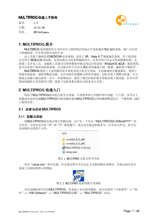
2.1 安装与启动MULTIPROG2.1.1 安装与启动将MULTIPROG的安装压缩文件解压缩,会产生一个名为“MULTIPROGX.XXBuildYYY”的文件夹,文件夹名中的“X”和“Y”都是数字,表示该安装包的版本号。
打开该文件夹,其中会有如图所示的四个文件。
图2.1 MULTIPROG安装文件夹内容双击“setup.exe”即可安装,在安装过程中可以自定义安装的根目录路径,安装完成后会在桌面上出现如图所示的图标。
图2.2 MULTIPROG桌面快捷方式图标双击该图标即可启动MULTIPROG。
Handy Recorder H1快速上手指南说明书

9
Upgrading the firmware
Upgrade the firmware version en necessary. MEMO
Check the firmware version when the unit is starting up. Version 1.00 is shown as “1/00,” for example.
Ditto X4 快速上手指南说明书

Quick Start Guide(1) STORE/LEVEL switches – Briefly flip the switch up to store the current loop asa backing track, or hold up for 3 seconds to delete stored backing track. Hold the switch in the down position while turning the associated LOOP knob to adjust the level of the backing track. (2) LOOP knobs – Adjust the level of a loop or backing track.(3) SERIAL/SYNC switch – When set to Serial, either loop 1 or 2 can be playedat a time. In Sync mode, both loops can be played simultaneously. (4) DECAY knob – Controls the amount of volume reduction that occurs each timean overdub repeats. (5) FX knob – Selects one of the 7 FX options.(6) LOOP 1 and 2 footswitches – Use these to control several loop-relatedfunctions. (see reverse side)(7) STOP footswitch – Press to stop both loops immediately.Hold to erase the loops. (8) FX footswitch – Press to engage the selected loop FX.DITTO X4 LOOPERLEGAL DISCLAIMERMusic Tribe accepts no liability for any loss which may be suffered by any person who relies either wholly or in part upon any description, photograph, or statement contained herein.Technical specifications, appearances and other information are subject to change without notice. All trademarks are the property of their respective owners. Midas, Klark Teknik, Lab Gruppen, Lake, Tannoy, Turbosound, TC Electronic, TC Helicon, Behringer, Bugera and Coolaudio are trademarks or registered trademarks of Music Tribe Global Brands Ltd. © Music Tribe Global Brands Ltd. 2019 All rights reserved.LIMITED WARRANTYFor the applicable warranty terms and conditions and additional information regardingMusic Tribe’s Limited Warranty, please see complete details online at /warranty. Zhongshan Eurotec Electronics LimitedNo. 10 Wanmei Road, South China Modern Chinese Medicine Park, Nanlang Town, 528451, Zhongshan City, Guangdong Province, ChinaSimple and Intuitive Dual-Track Guitar Looper Pedal with Powerful Loop Effects(9) INPUT jacks – Connect one ¼" TS cable for mono operation,or 2 cables for stereo. (10) OUTPUT jacks – Send audio via one or two ¼" TS cables. (11) Power input – Connect the 9V power supply. (9 V DC, >300 mA)(12) MODE switches – Adjust fine details of pedal’s operation.See the full manual for details. (13) USB input – Connect to a computer to transfer files back and forth,and for firmware updates. (14) MIDI jacks – Allows connection of an external MIDI clock,and program and CC changes from a MIDI controller. IMPORTANT SAFETY INSTRUCTIONBefore operating the device, please see “Important Safety Instructions” on page 3 of the full manual.Visit to download the full manual。
Kramer RC-208 快速上手指南说明书
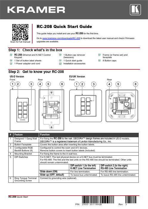
Scan for full manualRC-208 Quick Start GuideThis guide helps you install and use yourRC-208 for the first time.Go to /downloads/RC-208to download the latest user manual and check if firmwareupgrades are available.Step 1: Check what’s in the boxRC-208 Ethernet and K-NET Control Keypad1 Button-cap remover(tweezers)Frame (or frame set) and faceplate 1 Set of button label sheets 1 Quick start guide 8 Button caps 1 Power adapter and cordInstallation accessoriesStep 2: Get to know your RC-208US-D Version EU/UK Version FrontRearFrontRearStep 3: Configure RC-208To configure RC-208 buttons via K-Config:• Configure RC-208 (go to /product/RC-208).• Connect RC-208 to a PC via the Ethernet or connect via the mini USB port. •Sync the configuration to RC-208.To insert a button label for the first time:1. Cut out the appropriate button label from the buttonlabel sheets and place a label inside the button cover. 2. Cover with the button cap.To replace a label:1. Using the supplied tweezers, grip the button via theHorizontal or vertical ledges and remove the button cap. 2. Replace the label and cover the button with the buttoncap.You do not have to detach the faceplate to remove a button.Step 4: Connect the inputs and outputsAlways switch OFF the power on each device before connecting it to your RC-208. For best results, we recommend that you always use Kramer high-performance cables to connect AV equipment to RC-208.Step 5: Install RC-208After connecting the ports, insert the device into the in-wall box and connect the parts as shown in the illustrations below:EU/UK VersionUS-D VersionWe recommend that you use any of the following standard 1 Gang in-wall junction boxes (or their equivalent): •US-D: 1 Gang US electrical junction boxes.•EU: 1 Gang in-wall junction box, with a cut-hole diameter of 68mm and depth that can fit in both the device and the connected cables (DIN 49073).•UK: 1 Gang in-wall junction box, 75x75mm (W, H), and depth that can fit in both the device and the connected cables (BS 4662 or BS EN 60670-1 used with supplied spacers and screws).Step 6: Connect the powerConnect the 12V DC power adapter to the RC-208 and plug the adapter into the mains.Safety InstructionsCaution: There are no operator serviceable parts inside the unit.Warning: Disconnect the power and unplug the unit from the wall before installing.See for updated safety information.Step 7: Operate RC-208Operate RC-208 via the front panel buttons, as a room controller keypad configured via K-Config.。
Solaris Flare LR Q+ 快速上手指南说明书

Quick Start GuideSolaris Flare LR Q+ Quick Start GuideSolaris-Flare-LRQ+QSG-v1.0Effective 14 April 2021© Copyright 2021, TMBAll rights reservedTMB authorizes its customers to download and print this electronically published Quick Start Guide for professional use only. TMB prohibits reproduction, modification or distribution of this document for any other purposes, without express written consent. Specifications are subject to change without notice. The information in this document supersedes all previously supplied information before the effective date listed above. TMB has confidence in the accuracy of the document information herein but assumes no responsibility or liability for any loss occurring as a direct or indirect result of errors or exclusions whether by accident or any other cause.LIMITED WARRANTYSolaris fixtures are warranted by TMB against defective materials or workmanship for a period of two (2)years from the date of original sale by TMB.TMB’s warranty shall be restricted to the repair or replacement of any part that proves to be defective and for which a claim is submitted to TMB before the expiration of the applicable warranty periods.This Limited Warranty is void if the defects of the Product are the result of:•Opening the casing, repair, or adjustment by anyone other than TMB or persons specifically authorized by TMB•Accident, physical abuse, mishandling, or misapplication of the product.•Damage due to lightning, earthquake, flood, terrorism, war, or act of God.TMB will not assume responsibility for any labor expended, or materials used, to replace and/or repair the Product without TMB’s prior written authorization. Any repair of the Product in the field, and any associated labor charges, must be authorized in advance by TMB. Freight costs on warranty repairs are split 50/50: Customer pays to ship defective product to TMB; TMB pays to ship repaired product, ground freight, back to Customer.This warranty does not cover consequential damages or costs of any kind.A Return Merchandise Authorization (RMA) Number must be obtained from TMB prior to return of any defective merchandise for warranty or non-warranty repair. For all repairs please contact TMB Tech Support Repair using ************************************************************.US UK527 Park Ave. 21 Armstrong WaySan Fernando, CA 91340 Southall, UB2 4SD EnglandTel: +1 818.899.8818 Tel: +44 (0)20.8574.9700Fax: +1 818.899.8813 Fax: +44 (0)20.8574.9701******************************** SETUPS AFETY I NSTRUCTIONS• Keep this Quick Start Guide for future reference. If unit is sold to another user, make sure they also receive this instruction booklet.• Ensure the unit is connected to proper voltage, and that line voltage is not higher than that stated on the device.• Make sure there are no flammable materials close to the unit while operating.• Always disconnect from the power source before servicing or fuse replacement. Always use the fuse specified in this manual.• Maximum ambient temperature (Ta) is 40°C (104°F). Do not operate unit at temperatures above this rating.•In the event of a serious operating problem, stop using the unit immediately. Repairs must be carried out by trained, authorized personnel. Contact the nearest authorized technical assistance center. Only OEM spare parts should be used.• Do not connect the device to a dimmer pack.• Make sure power cord is never crimped or damaged.• Never disconnect power cord by pulling or tugging on the cord.Caution! There are no user serviceable parts inside the unit. Do not open the housing or attempt any repairs yourself. In the unlikely event your unit may require service, please contact your distributor.U NPACKING I NSTRUCTIONSUpon receipt of the unit, carefully unpack the carton and check the contents to ensure that all parts arepresent and in good condition. Notify the shipper immediately and retain packing material for inspection if any parts appear to be damaged from shipping or if the carton itself shows signs of mishandling. Save the carton and all packing materials. In the event that a unit must be returned to the factory, it is important that it be returned in the original factory box and packing.P OWER R EQUIREMENTSBefore powering the unit, make sure the line voltage is within the range of accepted voltages. This unitaccommodates 100-240VAC, 50/60Hz. All units must be powered directly from a switched circuit and cannot be operated with a rheostat (variable resistor) or dimmer circuit, even if the rheostat or dimmer channel is used solely for a 0-100% switch.Please read these instructions carefully. This user guide contains important information about the installation, usage, and maintenance of this product.Always consult a certified rigging specialistbefore suspending any device overhead. R IGGING S OLARIS F LARE Q+ LRSolaris Flare Q+ LR weighs approx. 24.3 lbs (11 kg) and requires multiple attachment points for safety. Use ProBurger ® couplers or equivalent C- or O-type clamps for attaching to truss, rated for fixture weight. After establishing the desired position, tighten all appropriate bolts.• Always use safety cables!• When selecting installation location, consider routine maintenance.• Team lift the fixture into mounting location, never try to mount fixture with one person.• Never mount fixture where it will be exposed to excess moisture, high h umidity, extreme temperatures, orrestricted ventilation for long periods of timeS OLARIS F LARE Q+ LR A TTACHABLE F EETSolaris Flare Q+ LR has optional feet attachments which allow for floor mounting applications. The PreSet™ Yoke automatically snaps to 15° increments from -45° to +135° for ease of use and focusing.N AVIGATION O VERVIEWThe default menu display shows the current DMX address, mode and footprint, as well as the option to rotate the screen and enter further menu options. Four control panel buttons are located near each corner of the LCD Display.Press and hold the <MENU> button to scroll through the top-level menu items. Use the <Up> and <Down> buttons, located to the right of the LCD screen, to navigate the menu map and menu options. Press the < ✔ > button to access the menu function currently displayed or to enable a menu option. To return to the top of the menu map or menu without changing the value, press the < X > button.M ENU M APF LARE Q+LR P IXEL M APSolaris Flare Q+ LR feature 108 10W Cree LEDs located in 3 rows and 36 columns. The LEDs have multiple options of control, subdivided into different “pixel” quantities. In Advanced Control Modes the Flare Q+ LR has the additional function of selecting a desired pixel group.LEDs are grouped into the following pixel options:•1-pixel unit – 1 group of 108 LEDs•2-pixel unit – 2 groups of 54 LEDs•3-pixel unit – 3 groups of 36 LEDs•4-pixel unit – 4 groups of 27 LEDs•6-pixel unit – 6 groups of 18 LEDs•12-pixel unit – 12 groups of 9 LEDsNote! Each mode can be inverted when last pixel becomes the first.B ASIC C ONTROL M ODESBasic control modes for RGB and RGBW control the Flare Q+ LR as 1-pixel mode for color wash applications.Mode Channel DMX values Preset FunctionRGBW 8bit 10 - 255 0 - 100 Red Intensity 20 - 255 0 - 100 Green Intensity 30 - 255 0 - 100 Blue Intensity 40 - 255 0 - 100 White IntensityRGBW 16bit 10 - 255 0 - 100 Red Intensity HI Byte20 - 255 0 - 100 Red Intensity LOW Byte 30 - 255 0 - 100 Green Intensity HI Byte 40 - 255 0 - 100 Green Intensity LOW Byte 50 - 255 0 - 100 Blue Intensity HI Byte60 - 255 0 - 100 Blue Intensity LOW Byte 70 - 255 0 - 100 White Intensity HI Byte 80 - 255 0 - 100 White Intensity LOW ByteMode Channel DMX values Preset FunctionRGB 8bit 10 - 255 0 - 100 Red Intensity 20 - 255 0 - 100 Green Intensity 30 - 255 0 - 100 Blue IntensityRGB 16bit 10 - 255 0 - 100 Red Intensity HI Byte20 - 255 0 - 100 Red Intensity LOW Byte 30 - 255 0 - 100 Green Intensity HI Byte 40 - 255 0 - 100 Green Intensity LOW Byte 50 - 255 0 - 100 Blue Intensity HI Byte60 - 255 0 - 100 Blue Intensity LOW ByteS TROBE M ODESStrobe Value Breakdown:DMX Value DMX Percent Strobe Intensity0 - 5 0 - 2 Blackout6 - 255 3 - 100 Intensity levelStrobe Duration0 - 254 0 - 99 0 - 650ms (50Hz AC)255 100 HYPERStrobe Rate0 - 5 0 - 2 No flash6 - 255 3 - 100 0.5 - 25Hz (50Hz AC); 0.6 - 30Hz (60Hz AC)Strobe effects0 - 4 0 - 2 No effect5 3 Wash Override (only available in RGB Strobe and RGBW Strobe modes) 16 - 42 4 -16 Ramp up43 - 85 17 - 33 Ramp down86 - 128 34 - 50 Ramp up - down129 - 171 51 - 67 Random172 - 214 68 - 84 Lighting215 - 240 85 - 92 Spikes241 - 245 93 - 95 Burst (use Rate at full) 2246 - 250 96 - 98 "Meltdown" Random Pixels w/ Solid Background 3251 - 255 99 - 100 "Meltdown" Random Pixels w/ Burst Background4Mode Channel DMX Value Percent FunctionRGB Strobe 10 - 255 0 - 100 Red Strobe Intensity 20 - 255 0 - 100 Green Strobe Intensity 30 - 255 0 - 100 Blue Strobe Intensity 40 - 255 0 - 100 Strobe Intensity50 - 255 0 - 100 Strobe Duration60 - 255 0 - 100 Strobe Rate70 - 255 0 - 100 Strobe FXRGBW Strobe 10 - 255 0 - 100 Red Strobe Intensity 20 - 255 0 - 100 Green Strobe Intensity 30 - 255 0 - 100 Blue Strobe Intensity 40 - 255 0 - 100 White Strobe Intensity 50 - 255 0 - 100 Strobe Intensity60 - 255 0 - 100 Strobe Duration70 - 255 0 - 100 Strobe Rate80 - 255 0 - 100 Strobe FXStrobe OnlyMode 10 - 255 0 - 100 Strobe Intensity 20 - 255 0 - 100 Strobe Duration 30 - 255 0 - 100 Strobe Rate40 - 255 0 - 100 Strobe FXA DVANCED RGB S TROBE M ODESA DVANCED RGBW S TROBE M ODESRDM S ENSORS AND F UNCTIONSSolaris Flare Q+ LR can be operated via Remote Device Management (RDM) that will assist with fixture setup and maintenance.PID NameCategory - Status Collection0x0020 QUEUED_MESSAGECategory - RDM Information0x0050 SUPPORTED_PARAMETERS0x0051 PARAMETER_DESCRIPTIONCategory – Product Information0x0060 DEVICE_INFO0x0080 DEVICE_MODEL_DESCRIPTION0x0081 MANUFACTURER_LABEL0x0082 DEVICE_LABEL0x0090 FACTORY_DEFAULTS0x00C0 SOFTWARE_VERSION_LABELCategory - DMX512 Setup0x00E0 DMX_PERSONALITYDMX_PERSONALITY_DESCRIPTION0x00F0 DMX_START_ADDRESSCategory – Sensors0x0200 SENSOR_DEFINITION0x0201 SENSOR_VALUE0x0202 RECORD_SENSORSCategory – Control0x1000 IDENTIFY_DEVICE0x1001 RESET_DEVICECONTACT INFORMATIONLOS ANGELES HEADQUARTERS 527 Park Avenue | San Fernando, CA 91340, USA Tel: +1 818.899.8818 | Fax: +1 818.899.8813*************TMB 24/7 TECH SUPPORTUS/Canada: +1.818.794.1286 Toll Free: 1.877.862.3833 (1.877.TMB.DUDE)UK: +44 (0)20.8574.9739Toll Free: 0800.652.5418*******************LOS ANGELES +1 818.899.8818LONDON +44 (0)20.8574.9700NEW YORK +1 201.896.8600BEIJING +86 10.8492.1587CANADA +1 519.538.0888A full service company providing technicalsupport, customer service, and follow-up.Providing p roducts and services for the industrial, entertainment, installation, defense, broadcast, research, telecommunications, and signage industries.Servicing the global market from offices in Los Angeles, London, New York, Toronto, and Beijing.。
手机说明书快速上手指南轻松掌握手机的功能和操作

手机说明书快速上手指南轻松掌握手机的功能和操作手机说明书快速上手指南本指南旨在帮助您快速掌握手机的功能和操作,以便更好地使用手机。
请按照以下步骤进行操作,以便快速上手。
1. 开箱及组装打开手机包装盒,取出手机及相关附件。
检查手机、电池和配件是否完好无损。
如果有任何破损或遗漏,请立即联系售后服务。
插入SIM卡和电池:- 关机,并确保取下手机背盖。
- 找到手机背部的SIM卡插槽,根据说明插入SIM卡。
- 将电池插入手机背部的电池插槽中,确保电池与金属接触点对齐。
- 轻轻按下电池,直到听到“咔嗒”声,表示电池已固定。
连接充电器:- 将充电器插入手机底部的充电接口中。
- 将充电器插头插入电源插座。
- 等待片刻,直到屏幕上显示电池充电指示图标。
2. 开机设置和配置打开手机电源按钮,手机将开始启动。
按照屏幕上的提示进行设置和配置。
选择语言:- 在语言选择界面上,滑动屏幕以查看可用的语言选项。
- 点击您需要的语言以确认选择。
Wi-Fi连接:- 打开手机的设置菜单,找到Wi-Fi选项。
- 在可用的无线网络列表中,选择您要连接的Wi-Fi网络。
- 输入密码(如果需要),然后点击连接。
账户和设置:- 按照屏幕上的提示,设置您的Google账户或其他所需的账户。
- 根据您的个人喜好,调整手机的各项设置。
3. 主屏幕和应用程序管理主屏幕是您操作和访问手机的起点。
了解如何管理主屏幕和应用程序可提高您的使用效率。
添加和删除应用程序:- 长按主屏幕上的空白区域,直到出现菜单或弹出窗口。
- 选择“添加应用”或类似选项。
- 按照屏幕上的指示,选择要添加的应用程序,并将其放置在所需位置。
- 要删除应用程序,长按要删除的应用程序图标,然后将其拖到“删除”或类似选项上。
文件夹和小部件:- 长按主屏幕上的应用程序图标,将其拖动到另一个应用程序图标上,以创建文件夹。
- 您还可以在主屏幕上添加小部件,以便快速访问某些功能或信息。
4. 常用功能和设置了解手机的常用功能和设置,可以更好地满足您的需求。
快速入门指南

快速入门指南快速入门指南是一份旨在帮助用户快速上手使用某种产品、软件、技术或服务的文档。
本指南将为您提供一系列步骤和提示,以便您能够迅速熟悉并正确使用所需的内容。
以下是一个通用的快速入门指南示例,以帮助您理解如何编写和组织这样的指南。
一、前言在开始使用任何新产品或服务之前,了解基础知识和准备工作非常重要。
在本部分,我们将介绍您应该具备的先决条件和准备事项。
1. 了解产品/服务的背景和目的在使用任何产品或服务之前,了解其基本背景、用途和目的是至关重要的。
这将帮助您更好地理解它的功能和优势,以便在使用过程中更加得心应手。
2. 获取所需的软硬件设备某些产品或服务可能需要特定的软硬件设备才能正常运行。
在开始使用之前,请确保您已经具备了所有必要的设备和工具。
3. 熟悉产品/服务的界面和功能在正式使用产品或服务之前,花一些时间熟悉其界面和各种功能。
了解每个按钮、菜单或选项的作用将使您能够更加高效地操作和使用。
二、安装和配置本部分将指导您进行产品或服务的安装和配置步骤。
请按照以下步骤一步步进行操作。
1. 下载和安装根据提供的指南或官方网站,下载产品或服务的安装程序。
双击该程序,按照向导提示完成安装过程。
2. 创建账户/配置设置如果产品或服务需要账户才能使用,请按照向导提示创建一个新账户。
根据您的需求,进行必要的设置和配置,以确保适合个人或组织要求。
三、基本操作在您已经完成安装和配置之后,本部分将向您展示如何进行产品或服务的基本操作。
请按照以下步骤进行操作。
1. 登录和注销打开产品或服务应用程序,并使用您之前创建的账户登录。
在使用完毕后,确保正确地注销账户,以保护您的个人信息和数据安全。
2. 导航和菜单熟悉产品或服务的导航界面和主要菜单。
了解如何通过不同的选项和功能来导航和访问所需的内容。
3. 基本操作和功能学习基本的操作和功能,如新建、编辑、删除、保存、导入和导出等。
这些功能通常是您常用的,因此熟练掌握它们将提高您的工作效率。
YS-X6快速上手指南20120529

YS-X6快速上手指南1安装与连线注意:飞控与WIFI模块供电范围均为3s~6s锂电(略有余量),即10.8V~25.5V,并自动向RC 接收机提供5.7V电源,系统无需外接任何电源模块。
正确连接并加电后,飞控在几秒内初始化完毕,然后LED灯开始闪烁红灯,一个周期三次,表示系统连接正确,已正常启动。
上述“三闪红灯”为检查飞控硬件是否正常工作的标志,一切数据连通都建立在这个基础上。
如果加电后没有“三闪红灯”,请与厂家或者销售商联系。
否则,请仔细对照连接图检查连接方式,注意IMU或GPS连接上有任何错误,都有可能造成设备的烧毁。
2设置路由器第一步:下载YS-GCS。
必须安装至手机本身内存中。
Android系统在文件管理器中运行一次安装文件即可自动完成安装。
苹果系统下软件为APP越狱后方可安装软件。
参考“苹果安装说明”。
第二步:您需要自配一部无线路由器建立AP。
设置路由器SSID为“YS-X6-飞控序列号”,注意字母必须大写,密码为82890430,使用WPA2-PSK AES加密方法,且IP为192.168.1.1。
(您也可以使用带有热点功能的手机替代路由器,但必须保证手机热点可以设置SSID名和密码,且IP为192.168.1.1)第三步:用手机/平板电脑打开WLAN连接路由器。
(连通数据后,飞行过程中的所有数据均被记录在手机的YShj目录下,文件均可通过计算机上的工具回放进行飞行数据分析。
)唯一SSID:YS-X6-飞控序列号,密码:828904303.安装向导数据连通后,您可以使用手机地面站“设置”页面里的“安装向导”进行如下设置:(如果数据未连通,请仔细阅读以上两步)(1)校准通道(2)检查CH5和CH6通道,设置F/S(失控保护)(3)校准电调行程(4)设置飞机种类及参数。
填写当地的磁偏角,偏西为正,偏东为负。
(5)检查IMU、GPS安装方向。
安装向导完成后,即可进行手动试飞。
(磁偏角查询网站:/geomagmodels/struts/calcDeclination)http:// /4校准磁航向手动飞行时,无需校准磁航向。
- 1、下载文档前请自行甄别文档内容的完整性,平台不提供额外的编辑、内容补充、找答案等附加服务。
- 2、"仅部分预览"的文档,不可在线预览部分如存在完整性等问题,可反馈申请退款(可完整预览的文档不适用该条件!)。
- 3、如文档侵犯您的权益,请联系客服反馈,我们会尽快为您处理(人工客服工作时间:9:00-18:30)。
3. 首次安装时,需要安装Labview的运行支持文件,耗时较长,请耐心等待;
主界面
1. 在开始菜单,所有程序/所有应用中可以找到“Electronics Pioneer”的程序快捷方式: 2. 点击程序图片,可以启动主界面:
EPI-m102型
3. 主界面上的各种功能如下图所示:
逻辑分析仪 脉冲信号发生器 多功能数字IO
GND 电路地
10
8 12位并行数字输入DIN0
6 4
– DIN11,可接受5V电 平输入,最高采样率 200KSPS;可用于逻辑
2 信号分析仪
0
5V 3.3V和5V对外供电
10
8 12位并行逻辑输出,输 6 出电平3.3V和5V可选, 4 最高刷新率20KSPS; 2 可用于脉冲信号发生器
0
GND 电路地
识别到的设备
上位机版本号
易派固件版本
4. 各个仪器的功能之间存在复用关系,当一种仪器打开,复用功能的仪器无法使用,图标会变灰:
易派与电脑的连接
EPI-m102型
1. DFU按键用于升级易派固件
2. 请关注,如有最新的固 件发布,会附有具体的固件升级方法
1. 易派使用Micro USB线缆与电脑相连
2. 双击VCP_V1.4.0_Setup.exe运行驱动安装程序,不要修改安装路径;
3. 安装完毕后,进入C:\Program Files (x86)\STMicroelectronics\Software\Virtual comport driver
4. 选择你的操作系统文件夹([Win7] 或 [Win8], WinXP请选Win7, Win10请选择Win8):
模式1:并行IO
电路地 GND SPI_CS 11 A组GPIO2 9 A组GPIO0 7 I2C_SCL 5 USART_TX 3 SPI_MISO 1 3.3V对外供电 3.3V B组GPIO7 11 B组GPIO5 9 B组GPIO3 7 B组GPIO1 5 PWM4 3 PWM2 1 电路地 GND
易派与用户电路的连接
EPI-m102型
易派通过杜邦线与用户电路相连 用户电路插在易派上
易派通过转接板,使用标准示波器探头, 杜邦线,或灯笼线与用户电路相连
驱动安装(2)
EPI-m102型
常见驱动安装问题:
1. Windows识别为“unknown device”, 此情况代表USB枚举失败,多是硬件问题,请尝试更换USB线缆,更换USB口 ( 台式机请使用后置的USB口,他们是直接焊接在主板上的,信号质量和供电能力都更好),或者更换易派,或 更换一台电脑看看是哪一部分的硬件出了问题;
应用程序安装
EPI-m102型
1. 在易派发布包中找到“Electronics Pioneer V1.xx.rar”,解压后得到程序文件夹;双击安装 包中的setup.exe, 即可以开始安装过程;
2. 注意:安装过程中请关闭杀毒软件,例如360等,或者选择信任如果 杀毒软件或Windows提示未知发布商等信息;接受NI的许可证文件;
• 如果你是32位的操作系统,双击并安装dpinst_x86.exe • 如果你是64位的操作系统,双击并安装dpinst_amd64.exe 5. 插上易派,Windows会扫描并安装对应的驱动文件,易派在设备驱动器中会识别为一个虚拟串口:
6. 如果Windows提示驱动安装不成功,常有下面的两种情况:
NC 无连接
NC 无连接
GND 电路地
GND 电路地
S1 信号源输出通道1和2,双通道同步12位600KSPS直接数字频率合成(DDS),输出正弦波-3dB S2 带宽>50KHz,输出阻抗50Ω,输出信号幅度5mVpp-10Vpp,步进5mV;可用于信号源和扫频仪
数字接口定义
EPI-m102型
GND 11 9 7 5 3 1 3.3V 11 9 7 5 3 1 GND
打开“驱动安装方法压缩包”中“Ghost版Windows缺失的系统文件”文件夹,选择对应的操作系统:
• 复制mdmcpq.inf到C:\Windows\inf,如有同名文件,请选择覆盖; • 复制usbser.sys到C:\Windows\System32\drivers,如有同名文件,请选择覆盖。 • 重新安装驱动程序,或执行下面的步骤
2. 开启对外供电时线缆上可能有较大的电流,请 使用套装原配的USB线缆
3. 如果出现无法识别易派,或使用过程中频繁出 现掉线,死机等情况,请首先检查线缆质量和 USB口(尽量不要使用台式机前面板的USB口, 请使用后面板上的USB口)
GND GND GND GND GND GND GND GND GND GND GND GND GND GND GND
GND 10 8 6 4 2 0 5V 10 8 6
4 2 0 GND
电路地 A组GPIO3 A组GPIO1 I2C_SDA USART_RX SPI_MOSI SPI_CK 5V对外供电 B组GPIO6 B组GPIO4 B组GPIO3 B组GPIO0 PWM3 PWM1 电路地
模式2:多功能数字IO
易派: • 提供电源 • 提供信号源输出 • 提供示波器接口 • 提供多功能数字IO
EPI-m102型
Windows电脑/手机/平板: • 和易派通过USB线缆连接 • 上位机提供多种仪器界面
驱动安装(1)
EPI-m102型
1. 在易派发布包中找到“驱动安装方法压缩包”,解压后得到两个文件和一个文件夹;
2. Windows能识别出STM32 Virtual COM Port,但在设备管理器中的中显示为带有叹号的设备:
表示驱动安装不成功(Windows无法为易派分配COM口),如WINXP提示INF的服务安装段落无效,或WIN7以上操 作系统提示无法找到合适的驱动,请首先检查您的操作系统是否是Ghost版本的windows系统,精简的windows系统 会删掉一些系统文件,其中就包括我们要用到的几个,请尝试下面的步骤
快速使用入门
易派目前只能和Windows操作系统配合使用 1. 安装易派驱动:见驱动程序安装页 2. 安装易派上位机软件:见上位机软件安装页 3. 使用Micro USB线缆连接易派和电脑 4. 打开上位机软件和要使用的仪器 5. 连接易派和待测电路开始测试
EPI-m102型
使用中的易派
用户待测电路: • 输入电源由易派提供 • 输入模拟信号由易派模拟输出提供 • 输出模拟信号到易派的模拟输入口 • 输入数字控制信号由易派的数字输出端口提供 • 输出数字IO状态可由易派的数字输入端口获取
驱动安装(3)
EPI-m102型
1. 在叹号的设备上点击更新驱动程序 软件;
2. 点击浏览计算机以查找驱动程序软件; 3. 驱动文件路径为:C:\Program Files (x86)\STMicroelectronics\Software\Virtual COM Port Driver,点选包括子文件夹,点 击下一步,安装驱动
模拟接口定义
EPI-m102型
Hale Waihona Puke -12V +12V
±12V对外供电,额定最大输出电流±50mA
-5V ±5V对外供电,额定最大输出电流±50mA +5V
3.3V 3.3V对外供电,额定最大输出电流200mA
5KHz基准方波,可在示波器界面中开启,默认无输出
GND 电路地
AIN1 模拟输入通道1和2,双通道12位5MSPS同步采样,输入阻抗1MΩ,最大输入信号±25V,输入 AIN2 -3dB带宽>500KHz;可用于示波器,频谱图和扫频仪