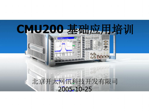
CMU200
CMU200在测试中模拟基站
CMU200在测试中模拟基站,通过U m接口,对无线终端产品的性能指标进行测试的综合测试仪CMU200还能作为信号源以及频谱分析仪,跟其他仪表配合起来使后面板主要由信号、同步的输入输出口以及远程控制、外围设备的接口和电源及其开关组成。
CMU200的基本单元中包含了信号源/功率计,示波器和简单的频谱分析仪的功能预选择菜单:MENU SELECT 菜单选择DA TA 文件管理CTRL 保留为以后扩展用* . E 特殊字符,小数点,十六进制“E”#_F 特殊字符,负号,十六进制“F”G/n mV A 109/10-9,单位,十六进制“A”M/u uV W B 106/10-6, 单位,十六进制“B”K/m dB uV C 103/10-3, 单位,十六进制“C”ON/OFF 编辑或者测试的打开/关闭CONT/HALT 进入/退出编辑,测试控制ESCAPE 退出下拉菜单,关闭编辑框,取消确认。
CLR 清除编辑的字符串←从右向左依次清除字符INS 在编辑框中插入或者重写有关内容INFO 系统信息和硬件诊断AUX1/2 辅助音频信号输入输出口,可能在远程控制中使用AF IN/OUT 音频信号的主输入输出端口IEEE488 GPIB线接口LPT 25pin 并口软件升级和版本管理利用软盘驱动或是用设备前部的PCMCIA接口来安装新的固件。
在这样的情况下新安装的软件属性必须把一段键码输入到相应的软件属性菜单里面才能激活。
如果CMU检测到软驱或PCMCIA插槽里的存储介质上有CMU固件的安装版本,那么在启动的时候版本管理器会自动的打开。
信号都可区分为以下5钟。
Signal Off CMU不传输信号Signal On CMU输出GSM控制信道信号给移动台同步Synchronized 与移动台取得同步且位置更新确认Alerting 移动台被CMU呼叫/震铃Call Established 移动台呼叫建立移动台测试前的准备第一步:将CMU电源插上。
CMU200综测仪操作手册
1.目的:规范综测仪的正确使用, 保证CDMA/GSM手机的射频参数测试的合理性与正确性。
2.参考资料:YDN 055-1997《900/1800MHz TDMA 数字蜂窝移动通信网移动台设备技术规范》EN 300 607-1(GSM 11.10-1)《数字蜂窝无线电通信系统(第2阶段)移动台一致性要求:部分1:CDMA2000数字蜂窝移动通信网设备总测试规范:移动台《R&S CMU200 使用说明书》3.仪器名称: 射频综测仪(型号:CMU200, 双模_GSM & CDMA2000)4.仪器自检和校准:为了能够保证每次的测试数据是准确的,经常需要对综测仪进行校准。
(1)打开综测仪的电源;(2)去掉与综测仪连接的全部射频线;(3)按“Menu Select”键选择“Basic Functions”→“Base”→“Maintenance”进“Maintenance”界面;(4)按“Select”键进行校准项选择,需校准项项目有“RXTX Selftest”和“FM Modulation Calibration”(5)按“Test“键后再按”ON/OFF”键开始校准,校准通过时会显示“Passed”提示。
5. 试验操作:5.1开机:(1)接好电源线(在仪器背面电源接口处标识相应的输入电压范围,通常接220V/50Hz电源), 按开机键, 进入待机界面;(2)开机预热30分钟后再准备测试。
(3)恢复仪器的原始设置:按“Reset”键后再按两次“Enter”键;5.2选择测试模块及网络标准:(1)此型号CMU200可以兼容不同制式的测试模块, 目前有GSM900, GSM1800, CDMA2000)。
选择不同制式测试模块(GSM或CDMA),所用选择和确认可用旋钮操作完成:选择为滚动旋钮,确认则按一下旋钮。
(2)GSM测试模块及网络标准选择:在待机界面按“Menu Select”选择“GSM Mobile Station”→“GSM900”或“GSM1800”,按“Enter”,选择GSM测试模块后“Network Standard”缺省为“GSM only”。
CMU200使用方法详解
名称 通 用 选 件 专 用 选 件 B11 B12 B17 Z10 B21 B52 K45 K21
1.4 CMU200 的基本操作
1.4.1 CMU200的控制面板 1.4.2 CMU200的按键及接口 1.4.3 外围设备的连接与设置 控制器连接 外部键盘连接 外部显示器连接 外部打印机 连接 外部同步设备的连接
1.4.2 CMU200的按键及接口
预选择菜单: MENU SELECT 菜单选择 DATA 文件管理 CTRL 保留为以后扩展用
数据输入: 0…9 数字输入 ENTER 确认 * . E 特殊字符,小数点,十六进制“E” #_F 特殊字符,负号,十六进制“F” G/n mV A 109/10-9,单位,十六进制“A” M/u uV W B 106/10-6, 单位,十六进制“B” K/m dB uV C 103/10-3, 单位,十六进制“C” *1 dBm dB D 100, 单位,十六进制“D” ON/OFF 编辑或者测试的打开/关闭 EXP/COMP CONT/HALT 进入/退出编辑,测试控制 UNIT 保留为以后扩展用
外部显示器连接
外接的VGA显示器可以通过15针SUB-D连接头连接到CMU200。
外部同步设备的连接
通过三个BNC连接器(REF in,REF out1
,REF out2)连接外围同步设备
1.4.3 外围设备的连接与设置
外部打印机连接
打印机可以通过并行接口LPT或串口1、2连接。在SETUP按键的PRINT页 面对其配置。
1.4.2 CMU200的按键及接口
ESCAPE 退出下拉菜单,关闭编辑框, 取消确认。 ON/STANDBY 测试模式跟待机模式的切换
CMU200 说明书
保留为以后扩展用 仪表设置 打印
值可变按键和组选择: 转动旋钮
在输入域可变值,表中选择 参数以及下拉菜单的选择。 可用于扩大或压缩表,按下 表示对所选内容的确认。 在下拉菜单中选择中光标 垂直移动 在下拉菜单中选择中光标 水平移动
垂直光标键
水平光标键
Further Keys 退出下拉菜单,关闭编辑框, 取消确认。 测试模式跟待机模式的切换
2 软件升级和版本管理
如果用户选择了“Activate other software”那么会出现如下界面:
例如, 如果用户选中了 “base 2X10.N03” 那么这一项就会显示红色, 如果用户点击 “Activate” 相关的热键,那么 CMU 就会自动完成安装。 如果用户选择了“Delete Software”那么会出现如下界面:
COMTEST 共 65 页
- 7 -
CMU200 操作手册
存储器上的启动配置。 如果 CMU 检测到软驱或 PCMCIA 插槽里的存储介质上有 CMU 固件的安装版本, 那么 在启动的时候版本管理器会自动的打开。版本管理器的主界面如下图:
如果用户要用不同的功能可以使用相应的软键激活。但是需要注意,如果这台 CMU 上 只存在一个软件版本的配置,那么激活其它软件属性的功能就失效。
CMU200 操作手册
CMU200 操作手册
COMTEST
共 65 页
- 1 -
CMU200 操作手册
目
录
第一章CMU200 简述 ......................................................................................................................3 一 CMU200 应用及其基本功能 .................................................................................................3 二 CMU200 的主要优点 .............................................................................................................3 三 CMU200 的按键及接口 .........................................................................................................3 1 CMU版本管理器 ...................................................................................................................7 2 软件升级和版本管理 ...........................................................................................................8 第二章 信令模式下移动台测试操作...........................................................................................13 一 二 三 四 五 六 CMU的 5 钟信令状态 ..........................................................................................................13 移动台测试前的准备 ...........................................................................................................17 GSM900 OVERVIEW ..............................................................................................................23 GSM900 POWER 测试 ..........................................................................................................29 GSM900 MODULATION测试 .................................................................................................45 GSM900 SPECTRUM测试 ......................................................................................................50 1 Modulation GMSK调制谱 ...................................................................................................50 2 Switching GMSK ..................................................................................................................54 七 GSM900 Receive Quality测试 ..........................................................................................57
CMU200综测仪操作手册.doc

1.目的:规范综测仪的正确使用, 保证CDMA/GSM手机的射频参数测试的合理性与正确性。
2.参考资料:YDN 055-1997《900/1800MHz TDMA 数字蜂窝移动通信网移动台设备技术规范》EN 300 607-1(GSM 11.10-1)《数字蜂窝无线电通信系统(第2阶段)移动台一致性要求:部分1:CDMA2000数字蜂窝移动通信网设备总测试规范:移动台《R&S CMU200 使用说明书》3.仪器名称: 射频综测仪(型号:CMU200, 双模_GSM & CDMA2000)4.仪器自检和校准:为了能够保证每次的测试数据是准确的,经常需要对综测仪进行校准。
(1)打开综测仪的电源;(2)去掉与综测仪连接的全部射频线;(3)按“Menu Select”键选择“Basic Functions”→“Base”→“Maintenance”进“Maintenance”界面;(4)按“Select”键进行校准项选择,需校准项项目有“RXTX Selftest”和“FM Modulation Calibration”(5)按“Test“键后再按”ON/OFF”键开始校准,校准通过时会显示“Passed”提示。
5. 试验操作:5.1开机:(1)接好电源线(在仪器背面电源接口处标识相应的输入电压范围,通常接220V/50Hz电源), 按开机键, 进入待机界面;(2)开机预热30分钟后再准备测试。
(3)恢复仪器的原始设置:按“Reset”键后再按两次“Enter”键;5.2选择测试模块及网络标准:(1)此型号CMU200可以兼容不同制式的测试模块, 目前有GSM900, GSM1800, CDMA2000)。
选择不同制式测试模块(GSM或CDMA),所用选择和确认可用旋钮操作完成:选择为滚动旋钮,确认则按一下旋钮。
(2)GSM测试模块及网络标准选择:在待机界面按“Menu Select”选择“GSM Mobile Station”→“GSM900”或“GSM1800”,按“Enter”,选择GSM测试模块后“Network Standard”缺省为“GSM only”。
CMU200中文操作指南
CMU200操作培训第一章CMU200简述一 CMU200应用及其基本功能CMU200在测试中模拟基站,通过U m 接口,对无线终端产品的性能指标进行测试的综合测试仪。
除此之外,CMU200还能作为信号源以及频谱分析仪,跟其他仪表配合起来使用。
作为一台综合测试仪,它几乎支持所有的协议:MS Test GSM400、900、1800、1900,TDMA IS 136,AMPS ,CDMA IS 95,WCDMA ,CDMA2000,EDGE 等等。
当然不同协议的支持需要我们加载不同版本的软件。
因此,可以说CMU200是完全面向未来的模块化设计。
由于CMU200的基本单元中包含了信号源/功率计,示波器和简单的频谱分析仪的功能,CMU200广泛的应用于下列各个领域:RF 开发 模块设计生产中的模块测试 生产中的最终测试 功能测试 特性测试 高级维修 质量检验测试系统的基本仪表 基站模拟二 CMU200的主要优点CMU200的设计不仅满足现在的测试需求,而且为以后的升级提供了很多备用资源。
它的有点主要体现在以下几个方面:多标准支持的测试平台 很快的测试速度 很高的测试精度 重量轻 耗电省 兼容性好三 CMU200的按键及接口CMU200的前面板主要是由VGA 显示屏以及VGA 两旁的软件以及下面的热键和右面的各类硬按键(FUNCTION 、SYSTEM 、DATA 、V ARIATION 、CONTROL )以及各类接口组成。
下图为CMU200的前视图。
www.mb tr en d .c o m图2-1 CMU200前视图CMU200的后面板如下图所示,主要由信号、同步的输入输出口以及远程控制、外围设备的接口和电源及其开关组成。
图2-2 CMU200后视图下面简单介绍一下各类按键以及接口。
FUNCTION预选择菜单: MENU SELECT 菜单选择 DATA 文件管理CTRL 保留为以后扩展用DATAwww.mb tr en d .c o m数据输入:0…9 数字输入(编辑字符串用的字母) * . E 特殊字符,小数点,十六进制“E ” #_F 特殊字符,负号,十六进制“F ” G/n mV A 109/10-9,单位,十六进制“A ” M/u uV W B 106/10-6, 单位,十六进制“B ” K/m dB uV C 103/10-3, 单位,十六进制“C ” *1 dBm dB D 100, 单位,十六进制“D ” ON/OFF 编辑或者测试的打开/关闭 EXP/COMPENTER 确认CONT/HALT 进入/退出编辑,测试控制 UNIT 保留为以后扩展用SYSTEM系统控制:HELP 保留为以后扩展用 SETUP 仪表设置 PRINT 打印V ARIATION值可变按键和组选择:转动旋钮 在输入域可变值,表中选择 参数以及下拉菜单的选择。
cmu200测试仪使用详解
由于 CMU200 的基本单元中包含了信号源/功率计,示波器和简单的频谱分析仪的功 能,CMU200 广泛的应用于下列各个领域:
RF 开发 模块设计 生产中的模块测试 生产中的最终测试 功能测试 特性测试 高级维修 质量检验 测试系统的基本仪表 基站模拟
二 CMU200 的主要优点
CMU200 的设计不仅满足现在的测试需求,而且为以后的升级提供了很多备用资源。 它的有点主要体现在以下几个方面:
但是如果在硬盘里面如果没有和用户选择相兼容的软件版本,那么会出现如下的出错提示 框:
最后当软件安装完成以后会出现如下的对话提示框:
点击“Finish installation”安装完成。 如果用户还要安装下个软件的时候,这时候 CMU 会自动检查是否有足够的硬盘空间,
如果不够的话,会出现如下对话框:
点击“Install ”,那么 CMU 会自动完成安装。但是如果要安装一个全新的固件的时候要么 对现有的版本进行升级要么创建一个新的,这时候会出现二选一的对话框,如下图:
但是需要注意的是如果用户安装的新的基本软件版本跟已经存在的软件版本不兼容的话,那 么这个对话框会被忽略,因为这时候必须进行全新的安装。如果升级存在的版本,用户可以 选择一个已经存在的配置然后代替基本的软件版本,这时候会出现如下的升级选择对话框:
CMU200的使用解读
在Alerting状态下,CMU可以通过Signal Off进入Signal Off状态;也 可以通过Disconnect Mobile进入Synchronized状态,当然也可能是 MS无应答的状态,CMU则返回Synchronized状态,如果MS作出相 应,通话链路建立起来,CMU进入Call Established 状态。当通话建 立后,CMU处于 Call Established状态,在此状态下,CMU可以返回 到除了Alerting外的任何状态。当然在Call Established状态下,CMU 可以通过Send SMS给MS发送短消息。
测试目的:
该测试主要是验证发射机发射的载频包络在一个时隙期间是否严 格满足GSM规定的TDMA时隙幅度上升沿、下降沿及幅度平坦部 分与模块的吻合程度。手机发射突发信号的上升与下降部分应在 +4dB~-30dB,模块范围之内,顶部起伏部分应在±1dB模板 范围之内。若突发信号超出模板范围,将会对使用临近时隙的用
测试原理:
手机发射部分由发射信号形成电路、功率放大电路、功率控制电路三个单元组成。 GSM频段分为124个信道,功率级别为5-33dBm,即Level 5~Level 19共15个级别; DCS频段分为373个信道(512-885),功率级别为0-30dBm,即Level 0~Level 15共 16个级别;每个信道有16个功率等级,测试时选上、中、下三个信道对每个功率等级 进行测试,每个功率等级以2 dBm增减。由于手机不断移动,手机和基站之间的距离 也跟着不断变化,因此手机的发射功率不是固定不变的,离基站远时发射功率大,离 基站近时发射功率小。具体过程如下:手机中的数据存储器(flash)存放有功率级别 表,当手机收到基站发出的功率级别要求时,在CPU的控制下,从功率表中调出相应 的功率级别数据,经数/模转换后变成标准的功率电平值,而手机的实际发射功率经 取样后也转换成一个相应的电平值,两个电平比较产生出功率误差控制电压,去调节 发射机激励放大电路、预放、功放电路的放大量,从而使手机的发射功率调整到要求 的功率级别上。
CMU200操作规范
CMU200操作规范一、开机界面的简介:对于CMU200的电源开关在该仪器面板的左下脚,按下该键后,设备进行自检(初始化),当初始化结束后按Menu Select ,屏幕就会显示以下两个菜单项:Basic Functions 和GSM Mobile Station 。
为了进行和手机通信,此时我们必须选择第二项:GSM Mobile Station,此时可以通过其面板上的箭头键或旋转旋钮来选择,在GSM Mobile Station菜单下它包括三个频段:GSM900、DCS1800、PCS1900,对于我们国内使用的频段为GSM900和DCS1800,PCS1900未利用因此我们暂对它不进行考虑;但对于出口到国外的产品我们在设计时对它的电性能指标也作严格的要求。
这时我们可以选择三个频段中任何一个作参考,按平时我们测试的习惯先测试GSM900,这里我们就选择以GSM900为例进行解说。
当选择该键后,它下面有两项:NonSignalling和Signalling. 根据测试需要我们选择第二项:Signalling,在该项下面有以下几项:A、Overview;B、Power;C、Modulation;D、Spectrum、E、Receiver Quality; F、Audio 共六项,下面对其进行介绍:1、若选择第一项Overview 它下面包括以下三项:a、p/t Normal GMSK b、Extphase Error GMSK c、Overview 8psk ,若要选择其中某一项也可通过旋纽或箭头键来选择,对于是否选择哪项,主要是看屏幕上蓝色对话框来确定,若该方框落在那一项上面就表示该项被选中,此时按回车键ENTER或按旋纽向里按一下即可。
对于CON/HALT按其中任何一项,都会出现一个对话框:GSM900 Connection Control 此对话框上方有一个手机图标在跳动,若此图标或处于静止状态中,可按Connection 后,再按Signal on.2、若选择Power ,它下面包括八项:a、p/t Normal GMSK ;b、p/t Normal 8psk ;C、p/t mulltislot;d、power Frame ;e、power slot Graph ;f、power slot Table;g、power pcl ;h、power access Burst;按其中任何一项,也会出现GSM900 Connection Control 此对话框上方有一个手机图标在跳动,若此图标或处于静止状态中,可按Connection 后,再按Signal on.。
联通CMU200移动无线通信测试仪说明书
Digital TDMA standardTDMA (time-division multiple access) is a mobile-radio system based on the TIA/EIA-136 standard, a system similar to GSM. TDMA is used in the United States and South Amer-ica in the cellular band (800 MHz) and the PC S band (1900 MHz). CMU200 covers both versions with Software CMU-K27 and CMU-K28. The narrow TDMA channel band-width of 30 kHz was chosen for rea-sons of compatibility with analog AMPS. TDMA is in fact a digital exten-sion of AMPS and for this reason is also referred to as DAMPS (dig-ital AMPS) (for more information on AMPS see page 14).TDMA triples AMPS capacity while boosting speech quality. Users of TDMA mobile phones profit from the advantages of the digital system mainly in conurbations, whereas across the vast expanses of the Ameri-can continent the excellent coverage provided by AMPS comes into its own.TDMA fits three calls into the 30 kHz bandwidth, the time being divided into 40 ms frames, each with six time-slots of 6.66 ms. Each call occupies two timeslots, ie the 1st and 4th, 2nd and 5th, or 3rd and 6th slot, mean-ing that each mobile sends a burst every third timeslot.The modulation mode used is π/4DQPSK (differential quadrature phase-shift keying). Each burst trans-mits 162 symbols. With every symbol encoding two bits, a total of 324 bits is transmitted.Universal Radio Communication Tester CMU200Successful mobile-radio testernow with US TDMA and AMPS standardsP h o t o 43238/11TDMA measurements in detailSimilar to the case with GSM, C MU200 [1] offers clear pop-up menus for all TDMA measurements; itsoperating concept is identical for allnetworks. Remote-control programs cre-ated for one network can for the most part also be used for other networks.The tester offers statistical evaluation and automatic limit-value checks for most measurements. Averaging is car-ried out by signal processors in the background, so measurement time is not slowed down by the output of pic-tures.Measurements are possible both in the signalling mode (with a call set up) and non-signalling mode. The latter is suitable for modules that do not allow complete call setup. For these mea-surements CMU200’s transmitter and receiver can be set in the frequency range 10 MHz to 2.7 GHz separately and independently of frequency band and channel spacing.Power versus timeFor TDMA systems it is essential that power be switched on and off exactly at the right times. The standard stipu-lates a 100 kHz filter for power-ver-sus-time measurements. Since this isnot a matched filter, power is not con-stant, not even at the symbol times.Power versus time can be displayed FIG 1 Results of power-versus-time measurement with eightfold oversam-pling shown in tolerance mask. A defective mobile would disturb com-munication in the adjacent timeslotFIG 2 Simultaneous and clear presentation of all results of modulationanalysis with CMU200with simple or eightfold oversampling. Marked power drops dependent on the modulation mode are visible only with a factor of 8 (FIG 1).Leakage power is the transmit power of a mobile between bursts. Here a maximum level of –60 dBm is allowed. High transmit power of the mobile calls for a wide dynamic range; for example, 30 dBm transmit power necessitates a dynamic range of 90 dB to check the stipulated switch-off level. This is not possible with a test filter of 100 kHz bandwidth in one and the same mea-surement. So CMU200 automatically performs a two-step measurement with range switching, thus providing the required dynamic range.For power-versus-time measurements in signalling mode, CMU200 features another application, ie checking of what are called shortened bursts. Short-ened bursts are used for timeslot syn-chronization during handoff and call setup. If this application is selected, the signalling unit of the tester causes the mobile to send shortened bursts and evaluates them in the power-versus-time measurement.Universal Radio Communication Tester CMU200 (photo left) is proving itself as a tester for all GSM versions in many mobile-phone production lines all over the world. Now it comes with two extra functions for non-GSM net-works – the US TDMA (IS-136) and AMPS standards. Unlike the situation in Europe, there are three competing digital mobile-radio networks in the United States: GSM, CDMA (IS-95) and TDMA (IS-136). Outside the USA, TDMA is becoming increasingly impor-tant in South America, which means a significant enlargement of its market. And there is a fourth system, analog AMPS, which serves as the second mode in CDMA and TDMA mobiles, so that a radio tester for their production and service must be able to handle the standard of the first-generation network too.Modulation analysisModulation quality is analyzed by measuring the error vector magnitude (EVM). The tester determines the error vector, ie the vector between the ideal and measured signal, at the symbol times and outputs the magnitude versus time. From the resulting data record, further parameters like peak EVM and rms EVM are calculated.To be able to use the measured data record for determining EVM however, other modulation errors like frequency error, timing error, origin offset and I/Q imbalance have to be determined and corrected in the data record. According to definition, they do not con-tribute to EVM and are to be regarded as separate error sources. CMU200 calculates all these parameters simul-taneously and presents them in clear form (FIG 2).CMU200 offers two more applications in modulation analysis: phase-error and magnitude-error measurement. As with EVM, these major parameters are output in graphical and numerical form. The overview menu for modulation analysis presents all numerical results at a glance (FIG 3). Measurementsare repeated at a fast rate, allowingrealtime adjustment of mobile-phoneparameters.Spectral measurementsThe standard calls for measurementsin the three nearest adjacent chan-nels above and below the transmis-sion channel. A distinction is madebetween two types of interference spec-trum. Firstly, there are transients causedby switching power on and off. Theyoccur at the beginning and end ofthe burst (spectrum due to switching).These spectral components are deter-mined in a peak-value measurement(ACP peak).The second type of interference spec-trum is caused by modulation (spectrumdue to modulation). The spectral com-ponents can be determined by averag-ing adjacent-channel power over adefined range in the middle of the burst(ACP rms). Here too, CMU200 standsout for extremely high measurementspeed. It covers all seven channels in asingle broadband measurement (FIG 4)and provides a statistical evaluationof results.For more in-depth analysis, for exam-ple of outliers, each channel can bedisplayed in the time domain and ana-lyzed by the ACP Time Domain applica-tion. In this way the cause of exces-sive adjacent-channel power can beanalyzed, for example high switch-ing transients at one of the two edges(FIG 5).Receiver measurementsReceiver measurements usually focuson bit error rate (BER); in CMU200they can be found in the Receiver Qual-ity menu. The TDMA standard specifiesa special mode of the mobile phonefor BER in which it is able to establish avoice channel independently – ie with-out signalling – and return receiveddata to the tester for evaluation (loop-back). BER measurement for TDMAis therefore included in the non-signal-ling group. An RF generator createsthe voice channel with random data,to which the mobile synchronizes inthe service mode. The bit errors arethen evaluated in the Receiver Qualitymenu.During a call, the mobile sends infor-mation to the base station. From this FIG 3 Summary of all numerical results of modulation analysis in OverviewmenuFIG 4 Spectrum due to modulation. In addition to current results, longtermpeak value (ACP Peak (Peak)), max. rms value (ACP Peak (RMS)) andaverage rms value (ACP Avg (RMS)) are output for all channelsinformation, the base station decides whether its transmit level has to be adjusted or the call handed over to another base station. C MU200 presents all information received from the mobile in the Receiver Quality menu (FIG 6).The values for BER and RSSI (radio signal strength indicator) refer to the currently active voice channel used by the mobile and the base station. BER is the bit error rate in coarse steps that the mobile recognizes during reception. RSSI is the power of the base station measured on the mobile’s antenna. Apart from information about its own channel, the mobile transmits power values measured on up to 24 adjacent channels. The channels to be logged are signalled to the mobile by the base station. These channels can be selected from a list in the Connection Control/ Network menu.HandoffsCMU200 of course supports all basic signalling functions such as registration, call setup, channel and timeslot hand-off. Since TDMA mobiles usually sup-port the three systems TDM (800 MHz), TDMA (1900 MHz) and AMPS, hand-offs, ie changes between these sys-tems, play an important role. CMU200offers handoff from any of the threenetworks into any other.Handoffs not only serve for testingthe handoff capability of mobiles.In production, they are used for rap-idly changing from one band or net-work to the next, thus saving the timerequired for renewed registration andcall setup.An interesting feature of CMU200 isthe possibility of defining the mobile’sresponse after breakdown of a callin a new network. There are two pos-sible versions: the old control chan-nel in the old network still exists, ora new control channel is set up inthe new system. Here, the mobile’sresponse and roaming time are of inter-est, ie the time the mobile needs to finda new control channel and, if neces-sary, register anew. The handoff menuprovides for complete handoff andhandoff with fallback, the latter mean-ing a return to the original networkafter a call breakdown.Other callsStandard IS-54 is a step on the wayto TDMA. Although it utilizes analogAMPS control channels, the voice chan-nel is digital. It also tripled voice-chan-nel capacity. This mechanism still existsin the system. Plus, if a mobile is regis-tered in one of the three networks, theprotocol enables direct call setup toany other network. CMU200 supportsthese versions too.AMPS measurements in detailHere, classic analog measurement engi-neering is used, in which CMU200is also at home thanks to its flexible,signal-processor-based concept. Mea-surements are organized into FM andaudio measurements for transmittersand receivers. AMPS measurementsare possible in signalling and non-signalling mode, which correspondsto normal call and service mode. Innon-signalling mode, the full CMU200frequency range from 10 MHz to2.7 GHz is available with 1 Hz reso-lution. So this mode is also suitablefor measurements on modules or foranalyzing intermediate frequencies. FIG 5 Excessive adjacent-channel power caused by high switching tran-sientsFIG 6 Mobile-assisted handoff (MAHO): information sent by mobile tobase station is listed in Receiver Quality menu of CMU200 signallingfunction groupAudio measurements can be per-formed with option CMU-B41, which is entirely based on digital signal process-ing. The filters in the audio path can be set over wide ranges. To ensure maximum ease of operation despite this high versatility, the default settings of filters and signals paths are those of the test specifications.In signalling mode the Analyzer/ Generator and Overview menus pro-vide a fast overview of the main mea-surements and settings (FIG 7). Transmitter testsIn the TX Tests/Modulation menu, all static transmitter measurements are car-ried out simultaneously (FIG 8). “Static”means measurements performed con-tinuously with constant instrument set-tings.The transmitter hum & noise measure-ment is carried out in two steps and is therefore separate from static measure-ments. In this application, two audio deviation measurements – with and without predefined modulation of the mobile transmitter – are performed. At the same time a modulated RF carrier is applied to the receiver. In the second step, the hum caused by crosstalk of the demodulator is measured. The hum & noise result is the ratio of the two measured results in dB.A special feature is AF level search. This finds the level of the CMU200 AF generator at which the desired target deviation of the mobile modulator is obtained. Since the deviation of the mobile transmitter is precisely defined for all modulation measurements and deviation varies from mobile to mobile, this is a highly efficient means of fulfill-ing the test specification. In this search routine, the user can freely select the start level and accuracy with which the target deviation has to be found. The required AF level is in most cases approximately known, so measurement time can be reduced to a fraction of a second. This is not possible with an IEC/IEEE-bus search routine or with manual control.Checking the AF frequency response is a very complex transmitter measure-ment. Test specifications stipulate a time-consuming sweep across the audio frequency range. With its TX AudioFIG 7 Main measurements at a glance: analyzer results and settings are shown on left, generator settings on right FIG 8 TX Tests/Modulation menu: all current instrument settings are shown on right. Frequency as well as AF generator level and frequency can be set with softkeys on rightAnalog AMPS standard AMPS (advanced mobile phone system) is an analog standard of the first generation based on frequency modulation in the 800 MHz band [2].C hannel bandwidth is 30 kHz, as with TDMA. Signalling information is partly transmitted in the form of simple tones (SAT and ST), and for longer telegrams – especially in the control channel – in the form of PSK-modulated AF signals at 10 kbit/s. It is still hard to imagine North and South American mobile radio without the “old” analog AMPS; its unpar-alleled advantage is excellent cov-erage. In addition to the modern networks, CMU200 supports AMPS, which still features in all CDMA and TDMA mobiles as a second mode. This combination benefits from the advantages of both techniques, ie the good coverage provided by AMPS and the quality offered by digital networks. Option C MU-K29 adds AMPS functionality to Radio C om-munication Tester CMU200, firming its reputation as a highly versatile multimode tester.Frequency Response menu, CMU200 offers a much faster alternative: it gen-erates up to 20 simultaneous tones with freely selectable frequency and level. This composite signal is then used to modulate the mobile transmitter. The analyzer measures the levels of the returned and demodulated tones. The audio frequency response is thus checked in one go (FIG 9). Receiver testsThe RX Tests menu (FIG 10) offers more in-depth receiver measurements. The AF signal demodulated by the mobile is evaluated. The AF analyzer measures the rms value, SINAD and distortion at the same time. For maximum measure-ment speed in production, CMU200 has a special SINAD remote-control command with selectable length of the test interval.The receiver hum & noise application is a two-step measurement. In this case, the hum on the demodulated AF signal is measured, caused for example by crosstalk of the mobile transmitter on the demodulator.Another application is receiver sensi-tivity. This parameter is defined as the input signal level at which the SINAD of the demodulated signal is still 12 dB. C MU200 performs this complex search automatically and at high speed.Just as for transmitters, a time-con-suming sweep is stipulated for check-ing receiver AF frequency response. CMU200 again offers multitone analy-sis, the RX Audio Frequency Response measurement, as an alternative. State-of-the-art measurementcapabilityIn the advanced features of CMU200, Rohde & Schwarz puts “old” mobile-radio measurement techniques on a new footing, satisfying the high stan-dards of mobile-radio production in the AMPS sector too.Ralf PlaumannFIG 9 Measurement of audio frequency response. Preset tolerance limits(red) mark expected preemphasis frequency response of transmitter. Theyare freely configurableREFERENCES[1]Mittermaier, Werner; Schmitz, Walter:Universal Radio C ommunication TesterCMU200 – On the fast lane into the mobileradio future. News from Rohde & Schwarz(1999) No. 165, pp 4–7[2] Rösner, Thomas: Digital Radiocommunica-tion Tester CMD80 – CDMA, AMPS andIS-136 measurements with one unit. Newsfrom Rohde & Schwarz (1999) No. 165,pp 10–12Reader service card 168/03FIG 10 AMPS RX Tests menu for more in-depth receiver mea s urements.Current generator settings are listed on right。
- 1、下载文档前请自行甄别文档内容的完整性,平台不提供额外的编辑、内容补充、找答案等附加服务。
- 2、"仅部分预览"的文档,不可在线预览部分如存在完整性等问题,可反馈申请退款(可完整预览的文档不适用该条件!)。
- 3、如文档侵犯您的权益,请联系客服反馈,我们会尽快为您处理(人工客服工作时间:9:00-18:30)。
bbfar(笔笔发)原创,转载请务必注明出处!CMU200操作培训第一章CMU200简述一 CMU200应用及其基本功能CMU200在测试中模拟基站,通过U m接口,对无线终端产品的性能指标进行测试的综合测试仪。
除此之外,CMU200还能作为信号源以及频谱分析仪,跟其他仪表配合起来使用。
作为一台综合测试仪,它几乎支持所有的协议:MS Test GSM400、900、1800、1900,TDMA IS 136,AMPS,CDMA IS 95,WCDMA,CDMA2000,EDGE等等。
当然不同协议的支持需要我们加载不同版本的软件。
因此,可以说CMU200是完全面向未来的模块化设计。
由于CMU200的基本单元中包含了信号源/功率计,示波器和简单的频谱分析仪的功能,CMU200广泛的应用于下列各个领域:●RF开发●模块设计●生产中的模块测试●生产中的最终测试●功能测试●特性测试●高级维修●质量检验●测试系统的基本仪表●基站模拟二 CMU200的主要优点CMU200的设计不仅满足现在的测试需求,而且为以后的升级提供了很多备用资源。
它的有点主要体现在以下几个方面:●多标准支持的测试平台●很快的测试速度●很高的测试精度●重量轻●耗电省●兼容性好三 CMU200的按键及接口CMU200的前面板主要是由VGA显示屏以及VGA两旁的软件以及下面的热键和右面的各类硬按键(FUNCTION、SYSTEM、DATA、VARIATION、CONTROL)以及各类接口组成。
下图为CMU200的前视图。
图2-1 CMU200前视图CMU200的后面板如下图所示,主要由信号、同步的输入输出口以及远程控制、外围设备的接口和电源及其开关组成。
图2-2 CMU200后视图下面简单介绍一下各类按键以及接口。
FUNCTION预选择菜单:MENU SELECT 菜单选择DATA 文件管理CTRL 保留为以后扩展用DATA数据输入:0…9 数字输入(编辑字符串用的字母)* . E 特殊字符,小数点,十六进制“E”#_F 特殊字符,负号,十六进制“F”G/n mV A 109/10-9,单位,十六进制“A”M/u uV W B 106/10-6, 单位,十六进制“B”K/m dB uV C 103/10-3, 单位,十六进制“C”*1 dBm dB D 100, 单位,十六进制“D”ON/OFF 编辑或者测试的打开/关闭EXP/COMPENTER 确认CONT/HALT 进入/退出编辑,测试控制UNIT 保留为以后扩展用SYSTEM系统控制:HELP 保留为以后扩展用SETUP 仪表设置PRINT 打印VARIATION值可变按键和组选择:转动旋钮在输入域可变值,表中选择参数以及下拉菜单的选择。
可用于扩大或压缩表,按下表示对所选内容的确认。
垂直光标键在下拉菜单中选择中光标垂直移动水平光标键在下拉菜单中选择中光标水平移动Further KeysESCAPE 退出下拉菜单,关闭编辑框,取消确认。
ON/STANDBY 测试模式跟待机模式的切换CONTROL控制功能:CLR 清除编辑的字符串←从右向左依次清除字符INS 在编辑框中插入或者重写有关内容DEL 依光标擦除字符VOL 保留为以后扩展用AUTO 保留为以后扩展用INFO 系统信息和硬件诊断RESET 恢复出厂设置DATA1,DATA2 AUX3和SPEECHAF ConnectorsAUX1/2 辅助音频信号输入输出口,可能在远程控制中使用AF IN/OUT 音频信号的主输入输出端口RF ConnectorsRF1 RF2 射频信号输入输出口上面的指示灯表示射频信号相对与CMU是输入还是输出RF3 OUT 射频信号输出口RF4 IN 射频信号输入口Mains Switch主电源开关电源插头IEEE488 GPIB线接口 LPT 25pin 并口COM1 9pin 串口1COM2 9pin 串口2MONITOR 外置显示接口KEYBOARD 键盘接口Intermediate frequencyIF3 RX CH1CMU接收机中频BNC接头Refrence frequency参考频率接口AUX,SERVICE,AUX4,extensions 四、软件升级和版本管理利用软盘驱动或是用设备前部的PCMCIA接口来安装新的固件。
在这样的情况下新安装的软件属性必须把一段键码输入到相应的软件属性菜单里面才能激活。
通过CMU提供的版本管理器这样一个工具能是用户在同一设备里更方便的安装新的固件或者使用不同的应用和版本。
1 CMU版本管理器版本管理器是一个被设计成能以很方便的方式激活、删除、安装、结合以及列出不同的软件版本。
并且它提供了设备的硬件以及软件版本配置信息,并且能重新设置存储在随机存储器上的启动配置。
如果CMU检测到软驱或PCMCIA插槽里的存储介质上有CMU固件的安装版本,那么在启动的时候版本管理器会自动的打开。
版本管理器的主界面如下图:如果用户要用不同的功能可以使用相应的软键激活。
但是需要注意,如果这台CMU上只存在一个软件版本的配置,那么激活其它软件属性的功能就失效。
2 软件升级和版本管理如果用户选择了“Activate other software”那么会出现如下界面:例如,如果用户选中了“base 2X10.N03”那么这一项就会显示红色,如果用户点击“Activate”相关的热键,那么CMU就会自动完成安装。
如果用户选择了“Delete Software”那么会出现如下界面:如果用户点击了“Delete”的相关软键,那么当前的固件配置将会被删除,并且CMU会要求用户激活余下的软件版本中的一个。
如下图:如果用户点击了版本管理器里“Install software from PC—card slot 0”的相关软键,那么会出现如下界面:点击“Install ”,那么CMU会自动完成安装。
但是如果要安装一个全新的固件的时候要么对现有的版本进行升级要么创建一个新的,这时候会出现二选一的对话框,如下图:但是需要注意的是如果用户安装的新的基本软件版本跟已经存在的软件版本不兼容的话,那么这个对话框会被忽略,因为这时候必须进行全新的安装。
如果升级存在的版本,用户可以选择一个已经存在的配置然后代替基本的软件版本,这时候会出现如下的升级选择对话框:但是如果在硬盘里面如果没有和用户选择相兼容的软件版本,那么会出现如下的出错提示框:最后当软件安装完成以后会出现如下的对话提示框:点击“Finish installation”安装完成。
如果用户还要安装下个软件的时候,这时候CMU会自动检查是否有足够的硬盘空间,如果不够的话,会出现如下对话框:要求用户删除相应的软件版本,以腾出空间来安装新的软件。
版本管理器还有删除有效的随机存储器内容、扫描磁盘、列出磁盘上的所有软件版本、拷贝有效的随机存储器内容到磁盘上、磁盘碎片整理等功能。
第二章信令模式下移动台测试操作一 CMU的5钟信令状态CMU200信令模式下测试移动台,在进入测试之前,我们先了解以下CMU200的5钟不同信令状态。
在CMU信令模式下的测试,无论通话的建立、释放,以及无线移动网络的控制,信号都可区分为以下5钟。
Signal Off CMU不传输信号Signal On CMU输出GSM控制信道信号给移动台同步Synchronized 与移动台取得同步且位置更新确认Alerting 移动台被CMU呼叫/震铃Call Established 移动台呼叫建立根据不同的信令状态,会有5钟不同的Signalling菜单。
当一种信令状态的信号到达时,相应的菜单会自动打开。
下面这张图表示5钟信令状态之间的相互转换。
图2-1 CMU200信令测试模式下的状态转换。
在图2-2 , 2-3,2-4,2-5,2-6中,我们可以很清楚的看到CMU各种信令状态之间的相互转化。
图2-2 GSM900 Connection Control_Connection _Signal Off在Signal Off状态下,CMU跟移动台之间没有联系,CMU在这种状态下,只能切换到Signal On,通过按Signal On软键。
图2-3 GSM900 Connection Control_Connection _Signal OnCMU在Signal On状态可以通过Signal Off回到SignalOff状态,可以等待同步进入Synchronized状态,也可以通过拨打MS 按Connect Mobile进入Alerting状态。
在Signal On状态,CMU可以给移动台发短信,Send SMS。
图2-4 GSM900 Connection Control_Connection _Synchronized当CMU跟MS取得同步后,CMU进入Synchronized状态,在Synchronized状态下,CMU有时会因为MS的某种原因(譬如MS功率降低)转换到Signal On状态;在Synchronized状态下,可以通过Singal Off进入Singal Off状态;在Synchronized状态下,可以通过Connect Mobile进入Alerting状态;在Synchronized状态CMU可以给移动台发短信,Send SMS。
图2-5 GSM900 Connection Control_Connection _Alerting当CMU跟MS取得同步后,通过呼叫MS,CMU可以进入Alerting状态。
在Alerting状态下,CMU可以通过Signal Off进入Signal Off状态;在Alerting状态下,CMU可以通过Disconnect Mobile进入Synchronized状态,当然也可能是MS 的无应答,CMU返回Synchronized状态;在Alerting状态下,如果MS作出相应,通话链路建立起来,则CMU进入Call Established 状态。
图2-6 GSM900 Connection Control_Connection_Call Established当通话建立后,CMU处于Call Established状态,在这个状态下,CMU可以返回到除了Alerting外的任何状态。
当然在Call Established状态下,CMU可以通过Send SMS给MS发送短消息。
二移动台测试前的准备第一步:将CMU电源插上。
第二步:将已经插上SIM卡的移动台通过射频线连到CMU200的射频端口RF2<span style="font-family: 宋体; mso-ascii-font-family: 'TiWCDMA 手机的射频测试3GPP TS 34.121规定了WCDMAFDD手机的射频一致性测试要求。