机械手夹持器设计(含CAD图纸)
机械手课程设计cad图纸
机械手课程设计cad图纸一、课程目标知识目标:1. 学生能理解机械手的基本结构及其在设计中的功能。
2. 学生能掌握CAD软件的基本操作,包括绘图、修改、标注等。
3. 学生能运用CAD软件绘制出机械手的三视图,并正确表达尺寸。
技能目标:1. 学生能够运用CAD软件进行机械设计,具备初步的工程图纸绘制能力。
2. 学生能够通过实际操作,提高空间想象能力和解决问题的能力。
3. 学生能够通过团队协作,完成机械手的设计任务,提高沟通与协作能力。
情感态度价值观目标:1. 学生培养对机械设计和制造的兴趣,激发创新意识。
2. 学生在课程中培养严谨、细致的工作态度,提高责任感和成就感。
3. 学生通过课程学习,认识到团队合作的重要性,培养集体荣誉感。
分析课程性质、学生特点和教学要求,本课程将目标分解为具体学习成果,包括但不限于:1. 学生能独立完成机械手的三视图绘制,正确表达尺寸。
2. 学生能通过小组讨论,优化机械手设计,提高其性能。
3. 学生在课程结束后,能对CAD软件在机械设计中的应用有更深入的理解,为未来深入学习奠定基础。
二、教学内容1. 机械手基本结构及功能介绍:包括机械手的组成部分、工作原理及在设计中的应用。
- 教材章节:第二章 机械手基础知识- 内容列举:机械手的分类、结构、功能及其在设计中的重要性。
2. CAD软件基本操作与使用技巧:学习CAD软件的界面、绘图、修改、标注等功能。
- 教材章节:第三章 CAD软件应用- 内容列举:CAD软件的基本操作、绘图工具、修改工具、标注方法等。
3. 机械手三视图绘制与尺寸标注:学习如何利用CAD软件绘制机械手三视图,并正确表达尺寸。
- 教材章节:第四章 机械图纸绘制- 内容列举:三视图绘制方法、尺寸标注规范、视图布局等。
4. 机械手设计优化与团队协作:通过小组讨论,优化机械手设计,提高其性能。
- 教材章节:第五章 机械设计与优化- 内容列举:设计优化方法、团队协作技巧、沟通与协调等。
机械手的PLC控制(三维建模CAD图纸)
机械手的PLC控制(三维建模CAD图纸)摘要机械手是工业机器人系统中传统的任务执行机构,是机器人的关键部件之一。
机械手的机械结构采用滚珠丝杆、滑杆、等机械器件组成;电气方面有交流电机、变频器、传感器、等电子器件组成。
该装置涵盖了可编程控制技术,位置控制技术、检测技术等,是机电一体化的典型代表仪器之一。
本文介绍的机械手是由 PLC 输出三路脉冲,分别驱动横轴、竖轴变频器, 控制机械手横轴和竖轴的精确定位, 微动开关将位置信号传给 PLC主机;位置信号由接近开关反馈给 PLC 主机,通过交流电机的正反转来控制机械手手爪的张合,从而实现机械手精确运动的功能。
本课题拟开发的物料搬运机械手可在空间抓放物体,动作灵活多样,可代替人工在高温和危险的作业区进行作业,并可根据工件的变化及运动流程的要求随时更改相关参数。
本文在纵观了近年来机械手发展状况的基础上,结合机械手方面的设计,对机械手技术进行了系统的分析,提出了用驱动和? PLC?控制的设计方案。
采用整体化的设计思想,充分考虑了软、硬件各自的特点并进行互补优化。
对机械手的整体结构、执行结构、驱动系统和控制系统进行了分析和设计。
在其驱动系统中采用驱动,控制系统中选择?PLC的控制单元来完成系统功能的初始化、机械手的移动、故障报警等功能。
最后提出了一种简单、易于实现、理论意义明确的控制策略。
通过以上部分的工作,得出了经济型、实用型、高可靠型机械手的设计方案,对其他经济型 PLC控制系统的设计也有一定的借鉴价值。
关键词:?机械手,交流电机,可编程控制器(PLC),自动化控制,。
Abstract?Manipulator?industrial?robot?systems?traditional?mandate,?Robot?i s?one?of?the?key?components.?Manipulator?using?the?mechanical?structure?of?screw?b all,?slider,?and?other?mechanical?devices?composition??Electric?have?AC?motor,?inverter, sensor,andotherelectronic?device?components.?The?device?covers?a?programmable?control?technology,?position?control?technology,?detection?technology,?Mechatronics?i s?a?typical?representative?of?one?of?the?machines.?This?paper?presents?a?manipulator?by?three?P LC?output?pulse,?driving?horizontal,?the?vertical?axis?transducer,?control?manipulator?axi s?horizontal?and?vertical?positioning?precision,?micro?switches?position?signal?transmissio n?will?host?PLC??location?close?to?the?switching?signal?from?the?feedback?from?the?mainfram e?to?the?PLC,?through?the?exchange?of?Motor?reversion?to?control?the?manipulator?gripper?Zh ang,?thus?achieving?accurate?manipulator?movement?functions.?The?topics?to?be?develop ed?by?the?Manipulator?grasping?be?up?in?space?objects,?movements?flexible,?diverse,?can replacetheartificialheatand?dangerous?operation?conducted?operations,?According?to?the?wo rkpiece?can?change?the?campaign?process?and?the?requirements?of?any?changes?to?the?relev ant?parametersIn?this?paper,?by?reviewing?the?developmental?status?of themanipulatorinrecentyears,combining?the?design?of?manipulator?and?systematic?analyzing?tech nology?of?the?manipulator,?We?proposed? the? design? scheme? that? the?manipulator?was? driven? by? the? pneumatic? and? the?system?was?controlled?by?PLC.?Integrative?idea?was?adopted?in?this?design?to? fully?consider?the? characteristics? of? the? software? and? hardware? and? complementary? optimizationWe?analyzed?and?designed?the?overall?structure,?the?implementation?o f?structural,?driving?system?and?control?system?of?the?manipulator.?We?used?pneumatic?driven?i n?the?driving?system,?PLC?control? unit? in? the? control? system? to? complete? initialization? of? the? system,? manipulator's?moving,? failure?alarm?and?so?on.?Finally?we?put? forward?a?control? strategy?which? is? simple,?easy?to?realize,?and?clear?theoretical?significanceThrough? the? work? above,? a? practical,? economical,? high?reliability? sorting? material?manipulator? was? designed,? which? also? had? certain? reference? value? for? the? other? types? of?economical?PLC?control?system?design.Key?words:?manipulator?;?AC?motor?;programmable?logic?controller?PLC; automatic?control;sorting?material第一章前言1.1 研究的目的及意义工业机械手是近代自动控制领域中出现的一项新的技术,是现代控制理论与工业生产自动化实践相结合的产物,并以成为现代机械制造生产系统中的一个重要组成部分。
曲轴搬运机械手含全套图纸
摘要机械手也被称为自动手。
工业机械手是近代自动控制领域中出现的一项新技术,并已渐成为现代机械制造系统中的一个重要组成部分。
这种新技术发展很快,逐渐形成一门新兴的学科一机械手工程。
随着科学技术的发展,机械手也越来越多的地被应用。
在机械工业中,铸、焊、铆、冲、压、热处理、机械加工、装配、检验、喷漆、电镀等工种都有应用的实理。
其他部门,如轻工业、建筑业、国防工业等工作中也均有所应用。
本文将设计一台四自由度的曲轴搬运上线机械手,目的是为了提高曲轴加工过程中的劳动生产率,实现机械加工的自动化。
根据机械手的工作要求和结构特点,进行了机械手的总体设计,确定了机械手的外形尺寸和工作空间,拟定了机械手各关节的总体传动方案。
除此之外,本设计的另一重要工作是对UG制图软件的简单学习,利用UG软件进行三维的仿真设计,使其的结构清晰明了。
除此之外,还要对本设计进行二维的平面设计,通过制图软件AutoCAD的学习,绘制出相应的总装图以及零件图。
最后,本设计对搬运机械手的自身结构进行大胆的创新与设计,其结构的实践性仍需进行改进与研究,因此,对其的研究与创新仍需很大的努力。
关键词:机械手;结构;仿真;制图AbstractManipulator is also know as automatic manipulator, Modern industrial manipulator is a new technology in automatic control field, and has gradually become the modern machinery. Manufacturing is an important component part of the system. The new technology develops very fast. Gradually formed an emerging discipline——Gradually formed an emerging discipline. With the development of science and technology, robots are also more and more applications. In the mechanical industry, casting, welding, riveting, punching, pressing, heat treatment, machining, assembly, inspection, painting, electroplating and other type of work has applied the real reason. Other departments, such as light industry, construction industry, national defense industry also have been used in our work.This paper will design a crankshaft handling online four degrees of freedom manipulator, The purpose is to improve the labor productivity in the process of crankshaft machining,to realize the automation of mechanical processing. According to the job requirements and structure characteristics of the manipulator, determine the overall dimensions of the manipulator and working space, and determine the overall dimensions of the manipulator and working space.in addition to this.This design is another important job of UG graphics software is simple to learn. Using the UG software for 3 d simulation design, make the structure clearly. Through the study of drawing software AutoCAD, draw the corresponding assembly drawing and part drawing.Finally, the design of carrying manipulator itself structure and bold innovation and design. The structure of the practice still need to improve and research, therefore, the research and innovation still needs great efforts.Keywords:manipulator;Structure;The simulation;Drawing目录摘要 (I)Abstract (II)1 绪论.....................................................................................................................................错误!未定义书签。
(有CAD图)P13-1-气动机械手的设计及其PLC控制-气要点

中文题目:基于 PLC 的机械手移动物体控制系统的设计外文题目:DESIGN A MANIPULATOR CONTROLLING SYSTEM WITH PLC1摘要在工业生产和其他领域内,由于工作的需要,人们经常受到高温、腐蚀及有毒气体等因素的危害,增加了工人的劳动强度,甚至于危及生命。
自从机械手问世以来,相应的各种难题迎刃而解。
机械手可在空间抓、放、搬运物体,动作灵活多样,适用于可变换生产品种的中、小批量自动化生产,广泛应用于柔性自动线。
机械手一般由耐高温,抗腐蚀的材料制成,以适应现场恶劣的环境,大大降低了工人的劳动强度,提高了工作效率。
机械手是工业机器人的重要组成部分,在很多情况下它就可以称为工业机器人。
工业机器人是集机械、电子、控制、计算机、传感器、人工智能等多学科先进技术于一体的现代制造业重要的自动化装备。
广泛采用工业机器人,不仅可以提高产品的质量与产量,而且对保障人身安全,改善劳动环境,减轻劳动强度,提高劳动生产率,节约原材料消耗以及降低生产成本,有着十分重要的意义。
本设计所用机械部件有滚珠丝杠、滑轨、气控机械抓手等。
电气方面有可编程控制器 (PLC 、编程器、电磁阀等部件。
由主机发出指令来实现对手臂的伸缩、上下、转动位置的控制;主机发信号到气动电磁阀,以控制手爪的张合来抓放物体。
本设计可根据工件的变化及运动流程的要求随时更改相关参数,具有很大的灵活性和可操作性。
关键词:可编程控制器;机械手;电磁阀2AbstractIn the industrial production and other fields, people often endangered by such factors as high temperature, corrode, poisonous gas and so forth at work, which have increased labor intensity and even jeopardized the life sometimes. The corresponding problems are solved since the robot arm comes out. The robot arms can catch, put and carry objects, and its movements are flexible and diversified. It applies to medium and small-scale automated production in which production varieties can be switched. And itis widely used on soft automatic line. The robot arms are generally made by withstand high temperatures, resist corrosion of materials to adapt to the harsh environment. So they reduced the labor intensity of the workers significantly and raised work efficiency. The robot arm is an important component of industrial robots, and it can be called industrial robots on many occasions. Industrial robot is set machinery, electronics, control, computers, sensors, artificial intelligence and other advanced technologies in the integration of multidisciplinary important modern manufacturing equipment. Widely using industrial robots, not only can improve product quality and production, but also is of great significance for physical security protection, improvement of the environment for labor, reducing labor intensity, improvement of labor productivity, raw material consumption savings and lowering production costs.There are such mechanical components as ball footbridge, slides, an air control mechanical hand and so on in the design. A programmable controller, a programming device, and electromagnetism valve are used in electrical connection. The mainframe send signals to control the opening and closing of the hand to carry objects. Related parameters can be changed according to request of the changes of the objects and movement flow at any time change the relevant parameters in the design, so it has great flexibility and operability.Key words: Programmable controller; Robot arm; electromagnetism valve3目录前言....................................................................................... 1 1机械手....................................................................................... 2 1.1机械手概况.............................................................................. 2 1.1.1机械手发展概况..................................................................... 2 1.1.2对机械手的一般要求............................................................... 2 1.1.3机械手的发展趋势.................................................................. 3 1.2机械手的组成、分类及型式......................................................... 3 1.2.1组成.................................................................................... 3 1.2.2分类.................................................................................... 4 1.2.3基本型式.............................................................................. 5 1.3机械手移动工件控制系统............................................................ 5 1.3.1机械手移动工件的基本结构、工作流程及工作原理 (6)1.3.2设备控制要求 (8)2 PLC....................................................................................... 9 2.1 PLC简介.............................................................................. 9 2.2 PLC发展趋势........................................................................ 10 2.3 PLC的结构和工作原理............................................................ 10 2.3.1 PLC的组成........................................................................... 10 2.3.2 PLC程序的表达方式............................................................... 13 2.3.3 PLC的工作方式 (14)43机械手移动工件控制系统的 PLC 选型及系统连接 (18)3.1 控制系统构成图..................................................................... 18 3.2 PLC 模块选型及介绍 (18)3.3 I/O地址分配及外部配线 (19)4安装维护 (21)4.1扩展设备组成........................................................................... 21 4.2现场环境................................................................................. 21 4.3安装工程................................................................................. 22 4.3.1安装注意事项 (22)4.3.2配线方面的注意事项 (23)5机械手移动工件控制系统程序设计 (24)5.1编程软件及应用 (24)5.2程序流程图 (24)6机械手移动工件控制系统 PLC 程序 (26)6.1系统资源分配........................................................................... 26 6.2源程序.................................................................................... 28 6.2.1总体安排.............................................................................. 28 6.2.2手动操作程序........................................................................ 29 6.2.3自动操作程序 (30)6.2.4操作系统总程序 (33)7技术经济分析 (37)7.1需求分析 (37)57.2控制系统的经济特点 (37)8结论………………………………………………………………………… 40 致谢……………………………………………………………………………… 41 参考文献................................................................................. 42 附录 A 译文.............................................................................. 43附录 B 外文文献 (52)61绪论1.1机械手概述工业机器人由操作机(机械本体、控制器、伺服驱动系统和检测传感装置构成,是一种仿人操作, 自动控制、可重复编程、能在三维空间完成各种作业的机电一体化自动化生产设备。
自动换刀机械手设计(机械CAD图纸)
摘要加工中心是指在一次装卡中,能够实现自动铣削、钻孔、镗孔、铰孔、攻丝等多工序的数控机床。
更为明确的说法是:加工中心就是自动换刀数控镗铣床。
这就把加工中心和自动换刀数控车床和车削中心区别开来。
加工中心区别于别的数控镗铣床的主要特点就在于它具有根据工艺要求自动更换所需刀具的功能,机自动换刀(ATC)机能。
加工中心的自动换刀系统,通常是由刀库和机械手组成,它是加工中心的象征,又是加工中心成败的关键环节。
因此各加工中心制造厂家都在下大力研制动作迅速、可靠性高的自动换刀装置,以求在激烈的竞争中取得好的效益。
正因为自动换刀装置是加工中心的核心内容,各厂家都在保密,极少公开有关资料,尤其机械手部分更始如此。
加重中心的自动换刀形式,可分为有机械手换刀方式和无机械手换刀方式。
加工中心的ATC,大都采用有机械手的换刀方式,因为更节省时间。
由于液压驱动的机械手需要采用严格的密封,还需较复杂的缓冲机构,控制机械手动作的电磁阀都有一定的时间常数,因为换刀速度较慢。
近年来国内、外先后研制出凸轮联动式单臂双抓机械手。
这种机械手的优点是由电机驱动,不需要较复杂的液压系统及其密封、缓冲机构,没有漏油现象,结构简单,工作可靠。
同时,机械手手臂的回转和插刀、拔刀的分解动作是联动的,部分时间可重叠,从而大大缩短了换刀时间。
关键词:机械手;加工中心;自动换刀AbstractMachining Center is installed in a card, to achieve automatic milling, drilling, boring, Reaming, Tapping and other processes of CNC machine tools. A more explicit statement of Machining Center is the automatic tool change CNC milling machines. This brings the processing center and automatic tool change CNC lathe and turning centers to distinguish. Machining Center is different from other CNC milling machines to the main features is that it has under the technological requirements for automatic tool change function, Automatic Tool Change (ATC) function.Machining Center, ATC system is usually a knife and the composition manipulator, it is a symbol of the processing center. Machining Center is the key to success. Therefore the processing center manufacturers are vigorously developing the next moves quickly, high reliability, ATC, to the fierce competition to achieve good results。
送料机械手设计_附机械手装配图.dwg,外观图.dwg_等
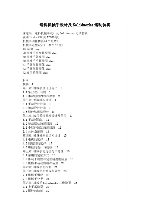
送料机械手设计及Solidworks运动仿真课题名: 送料机械手设计及Solidworks运动仿真说明书.doc(37页12000字)机械手动作仿真(4个短片)机械手造型设计(三维图70张)A3 活塞.dwga0机械手机身装配图.dwgA0机械手外观图.dwgA0机械手爪装配图.dwgA1手臂部装配体.dwgA2手腕部装配体.dwgA2液压系统图.dwg目录摘要 1第一章机械手设计任务书 11.1毕业设计目的 11.2本课题的内容和要求 2第二章抓取机构设计 42.1手部设计计算 42.2腕部设计计算 72.3臂伸缩机构设计 8第三章液压系统原理设计及草图 113.1手部抓取缸 113.2腕部摆动液压回路 123.3小臂伸缩缸液压回路 133.4总体系统图 14第四章机身机座的结构设计 154.1电机的选择 164.2减速器的选择 174.3螺柱的设计与校核 17第五章机械手的定位与平稳性 195.1常用的定位方式 195.2影响平稳性和定位精度的因素 195.3机械手运动的缓冲装置 20第六章机械手的控制 21第七章机械手的组成与分类 227.1机械手组成 227.2机械手分类 24第八章机械手Solidworks三维造型 258.1上手爪造型 268.2螺栓的绘制 30毕业设计感想 35参考资料 36摘要本课题是为普通车床配套而设计的上料机械手。
工业机械手是工业生产的必然产物,它是一种模仿人体上肢的部分功能,按照预定要求输送工件或握持工具进行操作的自动化技术设备,对实现工业生产自动化,推动工业生产的进一步发展起着重要作用。
因而具有强大的生命力受到人们的广泛重视和欢迎。
实践证明,工业机械手可以代替人手的繁重劳动,显著减轻工人的劳动强度,改善劳动条件,提高劳动生产率和自动化水平。
工业生产中经常出现的笨重工件的搬运和长期频繁、单调的操作,采用机械手是有效的。
此外,它能在高温、低温、深水、宇宙、放射性和其他有毒、污染环境条件下进行操作,更显示其优越性,有着广阔的发展前途。
毕业设计(论文)-关节型机械手设计-圆柱坐标式(全套图纸)
1
Abstract
In this paper, the design of the joint-type robot using cylindrical coordinates of type, can be completed on the expected, inversion and other functions. Mainly by the manipulator hand, wrist, arm and body parts, etc., with rotating wrists, arms stretching, arm movements and arm rotation four degrees of freedom, able to meet the general requirements of the industry.
2.1.3 控制系统
有点动控制和连续控制两种方式。大多数用插销板进行点位程序控制,也有 采用可编程序控制器控制、微型计算机数字控制,采用凸轮、磁带磁盘、穿孔卡 等记录程序。主要控制的是坐标位置,并注意其加速度特征。
2.2 关节型机械手的主要技术参数
1.抓重: 300N
7
2.自由度: 4个
3.坐标形式:圆柱坐标
1 绪论
机械手是近几十年发展起来的一种高科技自动化生产设备。它的特点是可通 过编程来完成各种预期的作业任务,在构造和性能上兼有人和机器各自的优点, 尤其体现了人的智能和适应性。机械手作业的准确性和各种环境中完成作业的能 力,在国民经济各领域有着广阔的发展前景。
1.1 研究目的及意义
工业机械手具有许多人类无法比拟的优点,满足了社会化大生产的需要,其 主要优点如下:
浇注机械手(含CAD图纸)
摘要本文简要介绍了工业机器人的概念,浇注机械手硬件和软件的组成,机械手各个部件的整体尺寸设计。
本文着重对机械手进行总体方案设计,确定了机械手的坐标形式和自由度,确定了机械手的技术参数。
同时,设计了机械手的夹持式手部结构,设计了机械手的手腕结构,计算出了手腕转动时所需的驱动力矩和回转液压缸的驱动力矩。
设计了机械手的手臂结构。
设计出了机械手的液压系统,绘制了机械手液压系统工作原理图,大大提高了绘图效率和图纸质量。
关键词:工业机器人机械手浇注机械手AbstractAt first, the paper introduces the conception of the industrial robot and the Eller. Dairy information of the development briefly. What’s more, the paper accounts for the background and the primary mission of the topic.The paper introduces the function, composing and classification of the manipulator, tells out the free-degree and the form of coordinate. At the same time, the paper gives out the primary specification parameter of this manipulator,The paper designs the structure of the hand and the equipment of the drive of the manipulator. This paper designs the structure of the wrist, computes the needed moment of the drive when the wrist wheels and the moment of the drive of the pump.The paper designs the structure of the arm.KEY WORDS:industrial robot manipulator pump air pressure drive第1章绪言机械工业是国民的装备部,是为国民经济提供装备和为人民生活提供耐用消费品的产业。
- 1、下载文档前请自行甄别文档内容的完整性,平台不提供额外的编辑、内容补充、找答案等附加服务。
- 2、"仅部分预览"的文档,不可在线预览部分如存在完整性等问题,可反馈申请退款(可完整预览的文档不适用该条件!)。
- 3、如文档侵犯您的权益,请联系客服反馈,我们会尽快为您处理(人工客服工作时间:9:00-18:30)。
1 / 59 机械手夹持器设计
2.1夹持器设计的基本要求
(1)应具有适当的夹紧力和驱动力;
(2)手指应具有一定的开闭范围;
(3)应保证工件在手指内的夹持精度;
(4)要求结构紧凑,重量轻,效率高;
(5)应考虑通用性和特殊要求。
设计参数及要求
(1)采用手指式夹持器,执行动作为抓紧—放松;
(2)所要抓紧的工件直径为80mm 放松时的两抓的最大距离为
110-120mm/s ,1s
抓紧,夹持速度20mm/s ;
(3)工件的材质为5kg ,材质为45#钢;
(4)夹持器有足够的夹持力;
(5)夹持器靠法兰联接在手臂上。
由液压缸提供动力。
2.2夹持器结构设计
2.2.1夹紧装置设计.
2.2.1.1夹紧力计算
手指加在工件上的夹紧力是设计手部的主要依据,必须对其大小、方向、作用点进行分析、计算。
一般来说,加紧力必须克服工件的重力所产生的静载荷(惯性力或惯性力矩)以使工件保持可靠的加紧状态。
手指对工件的夹紧力可按下列公式计算:123N F K K K G
2-1
式中:1
K —安全系数,由机械手的工艺及设计要求确定,通常取1.2——2.0,取1.5;2K —工件情况系数,主要考虑惯性力的影响,
计算最大加速度,得出工作情况系数2K , 20.02/1
11 1.0029.8a
K g ,a 为机器人搬运工件过程的加速度或减速度的
绝对值(m/s );。
