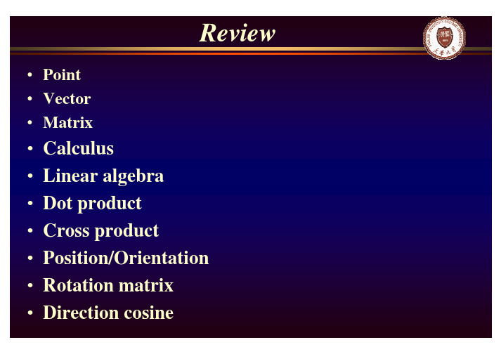
机器人学导论第三章参考答案
最新机器人学导论复习题及参考答案
中南大学网络教育课程考试复习题及参考答案机器人学导论一、名词解释题:1.自由度:2.机器人工作载荷:3.柔性手:4.制动器失效抱闸:5.机器人运动学:6.机器人动力学:7.虚功原理:8.PWM驱动:9.电机无自转:10.直流伺服电机的调节特性:11.直流伺服电机的调速精度:12.PID控制:13.压电元件:14.图像锐化:15.隶属函数:16.BP网络:17.脱机编程:18.AUV:二、简答题:1.机器人学主要包含哪些研究内容?2.机器人常用的机身和臂部的配置型式有哪些?3.拉格朗日运动方程式的一般表示形式与各变量含义?4.机器人控制系统的基本单元有哪些?5.直流电机的额定值有哪些?6.常见的机器人外部传感器有哪些?7.简述脉冲回波式超声波传感器的工作原理。
8.机器人视觉的硬件系统由哪些部分组成?9.为什么要做图像的预处理?机器视觉常用的预处理步骤有哪些?10.请简述模糊控制器的组成及各组成部分的用途。
11.从描述操作命令的角度看,机器人编程语言可分为哪几类?12.仿人机器人的关键技术有哪些?三、论述题:1.试论述机器人技术的发展趋势。
2.试论述精度、重复精度与分辨率之间的关系。
3.试论述轮式行走机构和足式行走机构的特点和各自适用的场合。
4.试论述机器人静力学、动力学、运动学的关系。
5.机器人单关节伺服控制中,位置反馈增益和速度反馈增益是如何确定的?6.试论述工业机器人的应用准则。
四、计算题:(需写出计算步骤,无计算步骤不能得分):1.已知点u的坐标为[7,3,2]T,对点u依次进行如下的变换:(1)绕z轴旋转90°得到点v;(2)绕y轴旋转90°得到点w;(3)沿x轴平移4个单位,再沿y轴平移-3个单位,最后沿z轴平移7个单位得到点t。
求u, v, w, t各点的齐次坐标。
xyzOuvwt2.如图所示为具有三个旋转关节的3R 机械手,求末端机械手在基坐标系{x 0,y 0}下的运动学方程。
机器人学导论(英) 第三讲
•Point•Vector•Matrix•Calculus•Linear algebra •Dot product •Cross product •Position/Orientation •Rotation matrix •Direction cosine•Coordinate system •Frame•Mapping •Translation •Rotation •Homogeneous transorm •Cross product •Operator •Translational operator •Rotational operator•Transformation operator •Compound transformation •Inverting a transformChapter3 Manipulator Kinematics•What is kinematics ?Kinematics is the sciences of motion that treats the subject without regard to the forces that cause it.•Example:With the knowledge of manipulator’s link length and joint angles, how to compute the position and orientation of the manipulatorsIn kinematics, we consider about the position, the velocity,the acceleration, and the higher derivatives of the position.The study of kinematics refers to all the geometrical and time-based properties of the motion.•Forward kinematicsGiven the joint variables of the robot, determine the position and orientation of the end-effector.[]12...T n θθθΘ=),,,,,(αβγz y x Y =•Kinematic ChainA robot can be treated as a set of right bodies (rigid links) connected together at various joints.•Lower pair:describe the connection between a pair of bodies when relative motion is characterized by two surface sliding over on another.•Joint type (lower pair):1. Revolute2. Prismatic3. Cylindrical4. Planar5. Screw6. Spherical•We consider the joint with 1degree-of-freedom (DOF). A joint with m DOF can be modeled as m joints of 1DOF connected by m-1links of zero length.•The action of joint can be described by a single real number: the angle of rotation in the case of a revolute joint, or the displacement in the case of a prismatic joint.•Number of the links starts from the immobile base (link 0), the first moving body is link 1and so on, out to the freed end of the arm, which is link n .…link1link2link0link6•In kinematics, a link is considered as a rigid body that define the relationship between two neighboring joint axes.1−i a axis i-1axis ilink i-11−i α1−i α:twist angle•Two parameters: link length and link twist angle are used to define the relative location of the two axes.•L ink length: the distance between two axes is measured along a line that is mutually perpendicular to both axes. This line is unique except in the case that two axes are parallel.axis i-1axis ilink i-1a1−ia:link length1−i•Imagine that a plane, whose normal is the mutuallyperpendicular line just constructed, we can project the axis i-1and axis i onto that plane and measure the angle from axis i-1to axis i by the right-hand rule .axis i-1axis ilink n-11−i α:twist angle1−i a•Intermediate links in the chain:Neighboring links has a common joint axis between them. The distance along this common axis from one link to another is defined as “link offset”. It will be variable for prismatic joint.axis i-1axis ilink i-11−iαid1−iaiθiaid:link offset•The angle that rotates about this common axis between one link and its neighboring link is defined as “joint angle ”. It will be variable for revolute joint.axis i-1axis ilink i-11−i αid 1−i a iθia i θ:joint angle•Link length and link twist angle depend on joint axes i and i+1.•For first link in the chain, we set and .00=a 00=α•For last link in the chain, we set and .0=n a 0=n α•If joint 1 is revolute, is set to be 0, zero position ofwill be chosen arbitrarily.1d 1θ•If joint 1 is prismatic, is set to be 0; zero position ofwill be chosen arbitrarily.1θ1d•Link parameters¾For revolute joint, the joint angle is called “joint variable”, and the other three quantities are fixed link parameters.¾For prismatic joint, the link offset is called “jointvariable”, and the other three link quantities are fixed link parameters.θd •Any robot can be described kinematically by giving the values of four quantities for each link, i.e., Denavit-Hartenberg notation[]i i iid a θαvariableconstant• A frame is attached to each link to describe the location of a link relative to its neighbors.•The link frame are named by number according to the link to which they are attached. Step1: frame {i}link {i}link1link2link0link6{0}{1}{2}{6}•Step2: intermediate link in the chain:iZ ˆjoint axis i frame {i}axis i-1axis ilink i-11−i αid 1−i a iθia 1ˆ−i Z 1ˆ−i X 1ˆ−i Y iZ ˆiX ˆiY ˆlink i•Step 3: direction of -along , from joint i to joint i+1iX ˆi a axis i-1axis ilink i-11−i αid 1−i a iθia 1ˆ−i Z 1ˆ−i X 1ˆ−i Y iZ ˆiX ˆiY ˆlink i•Step 4: direction of can be determined by right-hand rule ˆiY•How about if intersect ?is normal to the plane of and .i Z ˆ1ˆ+i Z iX ˆi Z ˆ1ˆ+i Z •First link in the chainsSelection of frame {0} is arbitrarily, will be selected along .0ˆZ 1ˆZ •Last link in the chainsFor revolute joint is chosen along when , the origin of frame {n} is chosen to set . n X ˆ0=n d 1ˆ−n X 0=n θFor prismatic joint, the direction of is chose to make and the origin of {n} is chosen at the intersection of and joint axis n when .0=n θnX ˆ1ˆ−n X 0=n daxis i-1axis ilink i-11−i αid 1−i a iθia 1ˆ−i Z 1ˆ−i X 1ˆ−i Y iZ ˆiX ˆiY ˆlink i•Summary of link parameters: the distance from to measured along : the angle from to measured about : the distance from to measured along : the angle from to measured about iX ˆi a i αi Z ˆ1ˆ+i Z i Z ˆ1ˆ+i Z iX ˆi d i θ1ˆ−i X i X ˆi Z ˆ1ˆ−i X iX ˆi Z ˆ•Summary of link-frame attachment procedure:Step1: identify the join axis (revolute joint/prismatic joint)Step2: identify the common perpendicular between two neighbouring joint axes, at the point of where the common perpendicular meets the i-th axis, assign the link-frame origin. (special case: the two axes intersect)Step3: assign the axis pointing along the i-th joint axis Step4: assign the axis pointing along the common perpendicular (special case: the two axes intersect)iX ˆi Z ˆStep5: assign the axis to complete a right-hand coordinate system.iY ˆStep6: assign the {0} to match {1} when first joint variable is 0.For {n}, chosen origin and directly of freely, but so as to cause as many link parameters as possible to be zero.nX ˆExample 3.3 in the text book(a)(b)Example 3.4 in the text bookwhere two adjacentaxes intersect(a)(b)D-H Tablei1−i a 1−i αid i θ11ˆZ 1ˆX 2ˆZ 2ˆX 3ˆZ 3ˆX 2L Link1Link2Link323D 90000)(2t d 2L )(1t θ)(3t θFrame {0} is coincident with frame {1}.Example 3.5 in the text bookwhere two adjacentaxes intersect•It is possible that there is no unique attachment of frames to link and result in several possible D-H representation.¾There are two choice of direction in which to point .¾In the case of intersecting axes, there are two choices fordirection of . 2ˆZ iX ˆ01=a 901−=α01=d 22L a =02=α12L d =1ˆZ 1ˆX 2ˆZ 2ˆX 3ˆZ 1L 2L case 111()t θθ=22()t θθ=−1=a 901=α01=d 22L a =02=α12L d −=1ˆZ 1ˆX 2ˆZ 2ˆX 3ˆZ 1L 2L case 2•When the direction of is changed, some link parameters willalso be changed. There are four more possible assignments offrames with pointing down.1X 11()t θθ=22()t θθ=1ˆZ•The above problem will be broken into four sub-sub-problems.Each sub-sub problem will be a function of only one link parameter.[]i i i i d a θα11−−Ti i1−•Sub-problem: construct the transform that define frame {i} to frame {i-1}•Problem statement: solve for the position and orientation of link n relative to link 0.•The problem can be broken into n sub-problem. Each sub-problem will involve transformation from one link to its neighboring link.•Introduce three intermediate frames: {P}, {Q}, and {R} for each link for transformationaxis i-1axis ilink n-11−iαid1−iaiθia 1ˆ−iZ1ˆ−iXiZˆiXˆRZˆRXˆQXˆQZˆPZˆPXˆ•Step1: {i}--->{P}, translation transform•Step2: {P}--->{Q}, rotation transform•Step3: {Q}--->{R}, translation transform•Step4: {R}--->{i-1}, rotation transform)(ˆi z P id D T i =)(ˆi z Q Pi R T θ=)(1ˆ1−−=i X R Qa D T i )(1ˆ11−−−=i X i Ri R T α)()()()(ˆˆ1ˆ1ˆ111i Z i Z i X i X i id D R a D R T iii i θα−−−−−=We can write))()()((11T T T T T P iQ P R Q i R i i−−=⎥⎥⎥⎥⎦⎤⎢⎢⎢⎢⎣⎡−−−=−−−−−−−−−−10001111111111i i i i i i i i i i i i i i i i i i i d c c s c s s d s s c c c s a s c T αααθαθαααθαθθθBy substituting the link parameters into above equation, we have•The Unimation Puma 560 is a robot with 6 degree of freedom, and all rotational joints (6R).•The link frames are assigned in the position corresponding to all joint angles equal to 0.forearm•Join axes of joint 4,5,6 intersect at a common point, and the joint axes 4,5,6 are mutually orthogonal. This design is used in many industrial robot.Schematic of the 3R wrist of PUMA 560•Link parameters of the PUMA 560 is listed in the following D-H table.•Transformation of each link can be computed as follows:•The transformation of all six link:•For a manipulator with n DOF, the position of all the links can be specified with a set of n joint variable. This set is often called as joint vector.•The space of joint vectors is referred as joint space.•Cartensian space: position is measured along orthogonal axes, and orientation is described by the rotation matrix wespecified before.•Cartensian space is often called as task-oriented space or operational space.•In the case that joint is not actuated directly by actuator, and the position sensors are often located at the actuators, actuator position should be considered.•Actuator vector: a set of actuator position•Actuator space: the space of actuator vectorsActuator SpaceJoint Space Cartesian Space•Base frame {B}, or frame {0}. It is attached to a non-moving part of the robot, i.e., the base, sometimes called link 0link1link2link0link6{B}{W}{T}{S}{G}link1link2link0link6{B}{W }{T }{S}{G}•The station frame {S}, located in a task-relevant location. Sometimes is called universe frame , task frame or world frame . It is often specified with respect to frame {B} as:TS B S =}{link1link2link0link6{B}{W }{T }{S}{G}•The wrist frame {W}, attached to the last link of themanipulator (frame {N}). It is defined relative to the base frame {B} asTT W N B W 0}{==link1link2link0link6{B}{W }{T }{S}{G}•The tool frame {T}, attached to the end of tool that the robot isholding. It can be defined according to wrist frame {W}.TT W T=}{link1link2link0link6{B}{W}{T }{S}{G}•The goal frame is utilized to describe the location to which therobot is to move the tool. It is specified relative to the station frame {S}.TG S G=}{•Where is the tool?The problem is to locate the position and the orientation of the tool that the robot is holding.))(()(1T T T T W TB W BS ST −=}{}{S T →•Example of the assignment of standard frames:Thank You!。
机器人学导论克雷格作业答案

2.1 soluti on:Accord ing to the equati on of pure tran siti on tran sformatio n,the new point2.3 soluti on:According to the constraint equations:Thus,the matrix should be like this:Solutio n:P Xcos 0 sin P n 片= : 010 P ° P Zsin0 cosP a2.7 Solutio n:According to the equation of pure rotation transformation , the new coord inates are as follows:10 02 2J 丄2二Rewrot(x,45) P 03 22 42 02 2 7「2 2222.9 Solutio n:Acording to the equations for the combined transformations ,the newcoord inates are as follows:0 1 0 0 5 1 0 0 0 5 1 A" r, B 1 0 0 0 3 0 0 1 0 3 10 P Rot(z,90 “)Trans(5,3,6) Rot(x,90?) P0 1 0 6 0 1 0 0 4 90 0 0 1 1 0 0 0 1 1 1Tran sformati ons relative to the reference frameTran sformati ons relative to the curre nt frame2.10BA P=Tra ns(5,3,6)Rot(x,90)Rot(a,90) PG 0 0 G <1 0 0 0> 「0-1 0 5 厂2 ‘0 10 3 0 0-10 10 0 0 3^0016^ ^0 10 0^ ^0 0 10^5 0 0 0 1 0 0 0 1 0 0 0 1 12-2812.12<^0.527 0.369 -0.766 -0.601、-1T1 = -0.574 0.819 0 -2.9470.628 0.439 0.643 -5.38厂0.92 0 -0.39 -3.8八-1T2 = 0 1 0 -60.39 0 0.92 -3.79丿0 0 0 12.14a) For spherical coord in ates we have (for posih on )1) r • cos 丫・sin [3= 3.13752) r • sin 丫・sin 3二2.1953) r • cos 3 二3.214I) Assuming sin p is posihve, from a and Y=35°from b and c — 3=50°unitsfrom c — r=5II) If sin 3were negative. ThenunitsSi nee orie ntati on is not specified, no more in formati on is available to check the results.b) For case I, substifate corresponding values of sin p , cos© S"Y COS YY=35°3=50 r=5and r in sperical coord in ates to get:3.1375、阿5265-0.5735 0.6275Tsph(r R Y=Tsph(35,50,5)= 0.3687 0.819 0.439 2.195-0.766 0 0.6428 3.214丿0 0 0 12.16Solutio n:Accord ing to the equati ons give n in the text book, we can get the Euler an gles as follows:Which lead to :2.18Solutio n:Si nee the hand will be placed on the object, we can obta in this:Thus:0 0 1 510 0 1U T H U T R0 10 00 0 0 1No,it can'.If so,the element at the position of the third row and the second column should be O.However, it is'.x=5,y=1,z=0Accord ing to the equati ons of the euler an gles:arctan2( a y , a x)orarctan2(a y,a x) O「or180arctan2( n x S n y C , o x S o y C ) 270or90;arctan2(a x C a y S ,a z) 270*or90*'2.21⑻(b)# 0 d a a 0-1 打0 01-2 □0 180 2-H □0 0(C )(d)1 0 0 00 1 0 00 0 1 d1d20 0 0 1C2 S2 0 d4C2 S2 C2 0 d4S2 0 0 1 0 0 0 0 1U T H U T°O T H U T O A I A2A3 2.22C1 Si 0 d a C1S1 C| 0 d a Si0 0 1 00 0 0 1C3 S3 0 0S3 C3 0 00 0 1 d50 0 0 1⑻(b)# 0 d a a 0-1 □+900 0 90 1-2 0 E 0 -90 =3-H 0 I3 0 0 (c)(d)2.23S1 0 C i 0C i 0 Si 00 1 0 00 0 0 1|10 0 1100 1 00 1 0 120 丄I A2! |1 0 0 0 01 0 0 0 0 1 13 k 0 0 丄凶=U T H T O°T H T0A1A2 A3A4LAI⑻1dfrrzrl>(b)# 0 d a a1 打0 0 902 □窗囲0 4 □0 1 -90(C)囚二1 0 0 00 0 1 00 1 0 00 0 0 10.707 0.707 0 10.610.707 0.707 0 10.610 0 1 60 0 0 1A2 囚二|10 0 100 1 00 1 0 00 0 丄(d) 1 0 0 0 0 0 1 0 0 1 0 18 0 0 0 1区]=0.707 0 0.707 00.707 0 0.707 00 1 0 00 0 0 1囲=|10 0 00 1 0 00 0 1 5A 0 0 丄1 0 0 1.4140 1 0 60 0 1 190 0 0 1。
最新机器人学导论复习题及参考答案

中南大学网络教育课程考试复习题及参考答案机器人学导论一、名词解释题:1.自由度:2.机器人工作载荷:3.柔性手:4.制动器失效抱闸:5.机器人运动学:6.机器人动力学:7.虚功原理:8.PWM驱动:9.电机无自转:10.直流伺服电机的调节特性:11.直流伺服电机的调速精度:12.PID控制:13.压电元件:14.图像锐化:15.隶属函数:16.BP网络:17.脱机编程:18.AUV:二、简答题:1.机器人学主要包含哪些研究内容?2.机器人常用的机身和臂部的配置型式有哪些?3.拉格朗日运动方程式的一般表示形式与各变量含义?4.机器人控制系统的基本单元有哪些?5.直流电机的额定值有哪些?6.常见的机器人外部传感器有哪些?7.简述脉冲回波式超声波传感器的工作原理。
8.机器人视觉的硬件系统由哪些部分组成?9.为什么要做图像的预处理?机器视觉常用的预处理步骤有哪些?10.请简述模糊控制器的组成及各组成部分的用途。
11.从描述操作命令的角度看,机器人编程语言可分为哪几类?12.仿人机器人的关键技术有哪些?三、论述题:1.试论述机器人技术的发展趋势。
2.试论述精度、重复精度与分辨率之间的关系。
3.试论述轮式行走机构和足式行走机构的特点和各自适用的场合。
4.试论述机器人静力学、动力学、运动学的关系。
5.机器人单关节伺服控制中,位置反馈增益和速度反馈增益是如何确定的?6.试论述工业机器人的应用准则。
四、计算题:(需写出计算步骤,无计算步骤不能得分):1.已知点u的坐标为[7,3,2]T,对点u依次进行如下的变换:(1)绕z轴旋转90°得到点v;(2)绕y轴旋转90°得到点w;(3)沿x轴平移4个单位,再沿y轴平移-3个单位,最后沿z轴平移7个单位得到点t。
求u, v, w, t各点的齐次坐标。
2.如图所示为具有三个旋转关节的3R 机械手,求末端机械手在基坐标系{x 0,y 0}下的运动学方程。
机器人技术第三章

c s 0 rc
s
c
0
rs
0 0 1 z
0
0
0
1
(绕原坐标系运动,左乘) (3-7)
Robotics运动学
3.1 机器人运动方程的表示
3.1.2 运动位置和坐标
2.用球面坐标表示末端运动位置
沿Z平移r,绕Y轴转β,绕Z轴转α.
Sph( , , r) Rot(z, )Rot( y, )Trans(0,0, r)
c s 0 0 c 0 s 01 0 0 0
s c 0 0 0 1 0 00 1 0 0 0 0 1 0 s 0 c 00 0 1 r
0
0 0 1 0 0 0 10 0 0 1
cc
sc s
3.1 机器人运动方程的表示
3.1.1 运动姿态和方向角
3.用滚\仰\偏转表示运动姿态
横滚:绕Z轴转φ,
RPY(, , ) Rot(z,)Rot( y, )Rot(x, ) c s 0 0 c 0 s 01 0
俯仰:绕Y轴转θ, s c 0 0 0 1 0 00 c
ny
oy
ay
py
scc
ss
scs cc
ss
0
n1z
oz 1
az 1
pz 1
sc
0
ss
c 0
0
0 1
对应项相等,有
(3-24)
Robotics运动学
3.2 机械手运动方程的求解
3.2.1欧拉变换解
nx ccc ss ny scc cs
机器人 习题 第三章重点

1、利用符号计算,推导坐标系{i-1}到坐标系{i}描述 (即课本P59公式3.6).m 文件脚本代码: %% Robot homework% define symbolic variable syms alphathetaad ;Rx = [1 0 0 0;...0 cos(alpha) -sin(alpha) 0;... 0 sin(alpha) cos(alpha) 0;... 0 0 0 1]; Dx = [1 0 0 a;... 0 1 0 0;... 0 0 1 0;...0 0 0 1];Rz = [cos(theta) -sin(theta) 0 0;... sin(theta) cos(theta) 0 0;... 0 0 1 0;... 0 0 0 1]; Dz = [1 0 0 0;... 0 1 0 0;... 0 0 1 d;... 0 0 0 1];T = (Rx * Dx) * (Rz * Dz) 结果: T =[ cos(theta), -sin(theta), 0, a] [ cos(alpha)*sin(theta), cos(alpha)*cos(theta), -sin(alpha), -d*sin(alpha)] [ sin(alpha)*sin(theta),sin(alpha)*cos(theta), cos(alpha), d*cos(alpha)][ 0, 0,0, 1]2、利用符号计算,推导3R 操作臂变换矩阵表达式 03T (即课本P55给定D-H 参数图3.8).并且:(i)用Matlab 编写3R 操作臂的运动学函数,即输入为3R 的D-H 参数,输出03T 矩阵;(ii)14L =,22L =,123[,,][0,0,0]T T θθθθ==;14L =,22L =,123[,,][10,20,30]TTθθθθ==14L =,22L =,123[,,][90,90,90]TTθθθθ==符号计算求3R 操作臂的03T 矩阵: %% Robot homework%% deduce 3R translation matrix%% ZhongHang all rights reserved...syms theta1theta2theta3L1L2;T1_0 = [cos(theta1) -sin(theta1) 0 0;...sin(theta1) cos(theta1) 0 0;...0 0 1 0;...0 0 0 1];T2_1 = [cos(theta2) -sin(theta2) 0 L1;...sin(theta2) cos(theta2) 0 0;...0 0 1 0;...0 0 0 1];T3_2 = [cos(theta3) -sin(theta3) 0 L2;...sin(theta3) cos(theta3) 0 0;...0 0 1 0;...0 0 0 1];T = T1_0 * T2_1 *T3_2结果为:T =[ cos(theta3)*(cos(theta1)*cos(theta2) - sin(theta1)*sin(theta2)) -sin(theta3)*(cos(theta1)*sin(theta2) + cos(theta2)*sin(theta1)), -cos(theta3)*(cos(theta1)*sin(theta2) + cos(theta2)*sin(theta1)) -sin(theta3)*(cos(theta1)*cos(theta2) - sin(theta1)*sin(theta2)), 0, L2*(cos(theta1)*cos(theta2) - sin(theta1)*sin(theta2)) + L1*cos(theta1)][ cos(theta3)*(cos(theta1)*sin(theta2) + cos(theta2)*sin(theta1)) +sin(theta3)*(cos(theta1)*cos(theta2) - sin(theta1)*sin(theta2)),cos(theta3)*(cos(theta1)*cos(theta2) - sin(theta1)*sin(theta2)) -sin(theta3)*(cos(theta1)*sin(theta2) + cos(theta2)*sin(theta1)), 0, L2*(cos(theta1)*sin(theta2) + cos(theta2)*sin(theta1)) + L1*sin(theta1)][0,0, 1, 0] [0,0, 0, 1] (i)、3R函数:function T = Cal3R(theta1, theta2, theta3, L1, L2)%% 3R Calculation%% This file is writed by zhonghang%% Hunan University all rights reserved...% angle transitiontheta1 = theta1 * pi /180;theta2 = theta2 * pi /180;theta3 = theta3 * pi /180;% Calculatesin(theta1) cos(theta1) 0 0;...0 0 1 0;...0 0 0 1];T2_1 = [cos(theta2) -sin(theta2) 0 L1;...sin(theta2) cos(theta2) 0 0;...0 0 1 0;...0 0 0 1];T3_2 = [cos(theta3) -sin(theta3) 0 L2;...sin(theta3) cos(theta3) 0 0;...0 0 1 0;...0 0 0 1];T = T1_0 * T2_1 *T3_2;(ii)、测试结果>>Cal3R(4, 2, 0, 0, 0)ans =0.9945 -0.1045 0 00.1045 0.9945 0 00 0 1.0000 00 0 0 1.0000>>Cal3R(4, 2, 10, 20, 30)ans =0.9613 -0.2756 0 49.78690.2756 0.9613 0 4.53100 0 1.0000 00 0 0 1.0000>>Cal3R(4, 2, 90, 90, 90)ans =-0.1045 -0.9945 0 179.28770.9945 -0.1045 0 15.68560 0 1.0000 00 0 0 1.00003、利用符号计算,给定D-H参数课本P62图3-21,计算PUMA560操作臂的正运动学矩阵4T、36T、13T、16T、06T6m文件脚本:%% Robot homework%% ZhongHang all rights reserved...% define symbol variablesyms theta1theta2theta3theta4theta5theta6;syms a2a3;syms d3d4;% Calculate Tsin(theta1) cos(theta1) 0 0;...0 0 1 0;...0 0 0 1];T2_1 = [cos(theta2) -sin(theta2) 0 0;...0 0 1 0;...-sin(theta2) -cos(theta2) 0 0;...0 0 0 1];T3_2 = [cos(theta3) -sin(theta3) 0 a2;...sin(theta3) cos(theta3) 0 0;...0 0 1 d3;...0 0 0 1];T4_3 = [cos(theta4) -sin(theta4) 0 a3;...0 0 1 d4;...-sin(theta4) -cos(theta4) 0 0;...0 0 0 1];T5_4 = [cos(theta5) -sin(theta5) 0 0;...0 0 -1 0;...sin(theta5) cos(theta5) 0 0;...0 0 0 1];T6_5 = [cos(theta6) -sin(theta6) 0 0;...0 0 1 0;...-sin(theta6) -cos(theta6) 0 0;...0 0 0 1;];% claculateT6_4 = T5_4 * T6_5T6_3 = T4_3 * T6_4T3_1 = T2_1 * T3_2T6_1 = T3_1 * T6_3T6_0 = T1_0 * T6_1运行结果:T6_4 =[ cos(theta5)*cos(theta6), -cos(theta5)*sin(theta6), -sin(theta5), 0][ sin(theta6), cos(theta6), 0, 0][ cos(theta6)*sin(theta5), -sin(theta5)*sin(theta6), cos(theta5), 0][ 0, 0, 0, 1]T6_3 =[ cos(theta4)*cos(theta5)*cos(theta6) - sin(theta4)*sin(theta6), - cos(theta6)*sin(theta4) - cos(theta4)*cos(theta5)*sin(theta6), -cos(theta4)*sin(theta5), a3][ cos(theta6)*sin(theta5), -sin(theta5)*sin(theta6), cos(theta5), d4][ - cos(theta4)*sin(theta6) - cos(theta5)*cos(theta6)*sin(theta4), cos(theta5)*sin(theta4)*sin(theta6) - cos(theta4)*cos(theta6), sin(theta4)*sin(theta5), 0] [ 0,0, 0, 1]T3_1 =[ cos(theta2)*cos(theta3) - sin(theta2)*sin(theta3), - cos(theta2)*sin(theta3) - cos(theta3)*sin(theta2), 0, a2*cos(theta2)][ 0, 0, 1, d3][ - cos(theta2)*sin(theta3) - cos(theta3)*sin(theta2), sin(theta2)*sin(theta3) - cos(theta2)*cos(theta3), 0, -a2*sin(theta2)][ 0, 0, 0, 1]T6_1 =[ - (sin(theta4)*sin(theta6) - cos(theta4)*cos(theta5)*cos(theta6))*(cos(theta2)*cos(theta3) - sin(theta2)*sin(theta3)) - cos(theta6)*sin(theta5)*(cos(theta2)*sin(theta3) + cos(theta3)*sin(theta2)), sin(theta5)*sin(theta6)*(cos(theta2)*sin(theta3) + cos(theta3)*sin(theta2)) - (cos(theta6)*sin(theta4) + cos(theta4)*cos(theta5)*sin(theta6))*(cos(theta2)*cos(theta3) - sin(theta2)*sin(theta3)), - cos(theta5)*(cos(theta2)*sin(theta3) + cos(theta3)*sin(theta2)) - cos(theta4)*sin(theta5)*(cos(theta2)*cos(theta3) - sin(theta2)*sin(theta3)), a3*(cos(theta2)*cos(theta3) - sin(theta2)*sin(theta3)) - d4*(cos(theta2)*sin(theta3) + cos(theta3)*sin(theta2)) + a2*cos(theta2)][- cos(theta4)*sin(theta6) - cos(theta5)*cos(theta6)*sin(theta4),cos(theta5)*sin(theta4)*sin(theta6) - cos(theta4)*cos(theta6), sin(theta4)*sin(theta5),d3][ (sin(theta4)*sin(theta6) - cos(theta4)*cos(theta5)*cos(theta6))*(cos(theta2)*sin(theta3) + cos(theta3)*sin(theta2)) - cos(theta6)*sin(theta5)*(cos(theta2)*cos(theta3) - sin(theta2)*sin(theta3)), (cos(theta6)*sin(theta4) + cos(theta4)*cos(theta5)*sin(theta6))*(cos(theta2)*sin(theta3) + cos(theta3)*sin(theta2)) + sin(theta5)*sin(theta6)*(cos(theta2)*cos(theta3) - sin(theta2)*sin(theta3)), cos(theta4)*sin(theta5)*(cos(theta2)*sin(theta3) + cos(theta3)*sin(theta2)) - cos(theta5)*(cos(theta2)*cos(theta3) - sin(theta2)*sin(theta3)), - a3*(cos(theta2)*sin(theta3) + cos(theta3)*sin(theta2)) - d4*(cos(theta2)*cos(theta3) - sin(theta2)*sin(theta3)) - a2*sin(theta2)] [0,0,0,1]T6_0 =[ sin(theta1)*(cos(theta4)*sin(theta6) + cos(theta5)*cos(theta6)*sin(theta4)) - cos(theta1)*((sin(theta4)*sin(theta6) - cos(theta4)*cos(theta5)*cos(theta6))*(cos(theta2)*cos(theta3) - sin(theta2)*sin(theta3)) +cos(theta6)*sin(theta5)*(cos(theta2)*sin(theta3) + cos(theta3)*sin(theta2))), sin(theta1)*(cos(theta4)*cos(theta6) - cos(theta5)*sin(theta4)*sin(theta6)) - cos(theta1)*((cos(theta6)*sin(theta4) + cos(theta4)*cos(theta5)*sin(theta6))*(cos(theta2)*cos(theta3) - sin(theta2)*sin(theta3)) - sin(theta5)*sin(theta6)*(cos(theta2)*sin(theta3) + cos(theta3)*sin(theta2))), - cos(theta1)*(cos(theta5)*(cos(theta2)*sin(theta3) + cos(theta3)*sin(theta2)) + cos(theta4)*sin(theta5)*(cos(theta2)*cos(theta3) - sin(theta2)*sin(theta3))) - sin(theta1)*sin(theta4)*sin(theta5), cos(theta1)*(a3*(cos(theta2)*cos(theta3) - sin(theta2)*sin(theta3)) - d4*(cos(theta2)*sin(theta3) + cos(theta3)*sin(theta2)) + a2*cos(theta2)) - d3*sin(theta1)][ - cos(theta1)*(cos(theta4)*sin(theta6) + cos(theta5)*cos(theta6)*sin(theta4)) - sin(theta1)*((sin(theta4)*sin(theta6) - cos(theta4)*cos(theta5)*cos(theta6))*(cos(theta2)*cos(theta3) - sin(theta2)*sin(theta3)) + cos(theta6)*sin(theta5)*(cos(theta2)*sin(theta3) + cos(theta3)*sin(theta2))), - cos(theta1)*(cos(theta4)*cos(theta6) - cos(theta5)*sin(theta4)*sin(theta6)) - sin(theta1)*((cos(theta6)*sin(theta4) + cos(theta4)*cos(theta5)*sin(theta6))*(cos(theta2)*cos(theta3) - sin(theta2)*sin(theta3)) - sin(theta5)*sin(theta6)*(cos(theta2)*sin(theta3) + cos(theta3)*sin(theta2))), cos(theta1)*sin(theta4)*sin(theta5) - sin(theta1)*(cos(theta5)*(cos(theta2)*sin(theta3) + cos(theta3)*sin(theta2)) + cos(theta4)*sin(theta5)*(cos(theta2)*cos(theta3) - sin(theta2)*sin(theta3))), d3*cos(theta1) + sin(theta1)*(a3*(cos(theta2)*cos(theta3) - sin(theta2)*sin(theta3)) - d4*(cos(theta2)*sin(theta3) + cos(theta3)*sin(theta2)) + a2*cos(theta2))][(sin(theta4)*sin(theta6) - cos(theta4)*cos(theta5)*cos(theta6))*(cos(theta2)*sin(theta3) + cos(theta3)*sin(theta2)) - cos(theta6)*sin(theta5)*(cos(theta2)*cos(theta3) - sin(theta2)*sin(theta3)), (cos(theta6)*sin(theta4) + cos(theta4)*cos(theta5)*sin(theta6))*(cos(theta2)*sin(theta3) + cos(theta3)*sin(theta2)) + sin(theta5)*sin(theta6)*(cos(theta2)*cos(theta3) - sin(theta2)*sin(theta3)),cos(theta4)*sin(theta5)*(cos(theta2)*sin(theta3) + cos(theta3)*sin(theta2)) - cos(theta5)*(cos(theta2)*cos(theta3) - sin(theta2)*sin(theta3)), - a3*(cos(theta2)*sin(theta3) + cos(theta3)*sin(theta2)) - d4*(cos(theta2)*cos(theta3) - sin(theta2)*sin(theta3)) - a2*sin(theta2)][0,0,0,1]。
机器人技术基础刘极峰部分3-5章习题解答

0
0
0 1
0
L1
L2
0 0 0
1
A2= Rot(Z, θ2)Trans(L3, 0, 0)Rot(X, 0º) = csions22
sin2 cos 2
0 0
L3 L3
cos 2 sin 2
0
0 1 0
0
00
1
cos3 sin 3 0 L4 cos3
d dt
L 1
[(m1
m2 )l12
m2l22
2m2l1l2c2 ]1 [m2l22
m2l1l2c2 ]2
2m2l1l2s212 m2l1l2s222
L 1
(m1
m2 )gl1s1
m2 gl2s12
第一个动力学方程为
0
0
0 1
0 1 0 3
3.5
A B
H
0
0 1 7
1 0 0 9
0
0 0 1
0 1 0 3
3.6
B B
H
0
0 -1 7
1 0 0 9
0
0
0
1
0 1 0 5
3.7
H
0
0 1 0
1 0 0 0
m2l22 (1
2 )2
m2l1l2c2 (12 12 ) (m1 m2 )gl1c1 m2 gl2c12
L 1
(m1 m2 )l121 m2l22 (1 2 ) m2l1l2c21 m2l1l2c22
《机器人概论》教学课件—第3章 机器人数学建模
项对应相等,因而
A B
R
AB
A B
R
(3)
实际上,对于任意旋转矩阵 R ,由其正交性,有 RRT In ,
其中 In 为 n 维单位矩阵;对上式两端求导,并令 S RRT ,则 S ST 0
连杆偏距(连杆间距离)di 关节角(连杆间夹角) i
显然,如果关节 i 是平移关节,则 di 是变量,i 是常数;如果关 节 i 是旋转关节,则 di 是常数,i 是变量。
15
2.建立连杆坐标系
为描述相邻连杆间的相对位置关系,在每个连杆上固连一个 坐标系。固连在连杆i上的固连坐标系记作坐标系{i}.
的旋转角速度为 AB ,空间点 Q 为坐标系{B}中 一固定点。
26
分析:由于 Q 相对于坐标系{B}固定,BVQ 0 , Q 点相对于坐 标系{A}的线速度仅由旋转角速度引起的。假设由于坐标系{B}
相对坐标系{A}以角速度 AB 旋转,则 Q 围绕 AB 的旋转轴沿圆
周运动,圆半径为 AQ sin ,其中 为 AQ 与旋转轴之间的夹角。
Xˆ B Xˆ B
Xˆ A YˆA
Xˆ
B
Zˆ
A
YˆB Xˆ A YˆB YˆA YˆB ZˆA
ZˆB ZˆB
Xˆ A YˆA
Zˆ
B
Zˆ
A
旋转矩阵的各分量又称”方向余弦” .
A B
R
B A
RT
可证明
A B
RT
A B
R
I3
A B
RT
R A 1
B
因此是正交矩阵,即各列模为1且互相正交. 同时可得到旋 转矩阵逆的计算方法:
23
位置矢量的微分
- 1、下载文档前请自行甄别文档内容的完整性,平台不提供额外的编辑、内容补充、找答案等附加服务。
- 2、"仅部分预览"的文档,不可在线预览部分如存在完整性等问题,可反馈申请退款(可完整预览的文档不适用该条件!)。
- 3、如文档侵犯您的权益,请联系客服反馈,我们会尽快为您处理(人工客服工作时间:9:00-18:30)。
题3.11 [17]图3-33所示为某一机器人腕部的示意图,它有三个相交
但不正交的轴。给出腕部的连杆坐标系(类似于3自由度操作臂),并
求连杆参数。
i αi-1 ai-1 di
θi
1 0 0 0
θ4
2 β 0 0
θ5
3 -β 0 0
θ6
题3.13 [15]建立图3-34所示的5自由度操作臂的连杆坐标系。
题3.15 [15]建立图3-35中的3自由度操作臂的连杆坐标系。
题3.16 [15]建立图3-36中RPR平面机器人的连杆坐标系,并给出连
杆参数。
。
i αi-1 ai-1 di
θi
1 0 0 0
θ1
2 -90 0 d2 0
3 90 0 0
θ3
题3.17 [15]建立图3-37中的三连杆机器人的连杆坐标系。
题3.18 [15]建立图3-38中的三连杆机器人的连杆坐标系。
题3.19 [15]建立图3-39中的三连杆机器人的连杆坐标系。
题3.20 [15]建立图3-40中的三连杆机器人的连杆坐标系。
题3.21 [15]建立图3-41中的三连杆机器人的连杆坐标系。
题3.22 [18]建立图3-42中P3R机器人的连杆坐标系。在确定坐标系
的布局后,确定d2、d3和a2的符号。
d2为负,d3为正,a2为正