电力机车变频空调系统说明书
空调系统安全指南说明书

This air conditioning system meets strict safety and operating standards.As the installer or service person, it is an important part of your job to install or service thesystem so it operates safely and effi ciently.For safe installation and trouble-free operation, you must:• Carefully read this instruction booklet before beginning.• Follow each installation or repair step exactly as shown.• Observe all local, state, and national electrical codes.• Pay close attention to all warning and caution notices given in this manual.T his symbol refers to a hazard or unsafe practice which can result insevere personal injury or death.This symbol refers to a hazard or unsafe practice which can result inpersonal injury and the potential for product or property damage.• Hazard alerting symbolsElectricalSafety/alertIf Necessary, Get HelpThese instructions are all you need for most installation sites and maintenance conditions.If you require help for a special problem, contact our sales/service outlet or your certifi eddealer for additional instructions.In Case of Improper InstallationThe manufacturer shall in no way be responsible for improper installation or maintenanceservice, including failure to follow the instructions in this document.When WiringELECTRICAL SHOCK CAN CAUSE SEVERE PERSONAL INJURY OR DEATH. ONLY AQUALIFIED, EXPERIENCED ELECTRICIAN SHOULD ATTEMPT TO WIRE THIS SYSTEM.• Do not supply power to the unit until all wiring and tubing are completed or reconnectedand checked.• Highly dangerous electrical voltages are used in this system. Carefully refer to the wir-ing diagram and these instructions when wiring. Improper connections and inadequateearthing (grounding) can cause accidental injury or death.• Earth (Ground) the unit following local electrical codes.• Connect all wiring tightly. Loose wiring may cause overheating at connection pointsand a possible fi re hazard.When TransportingBe careful when picking up and moving the indoor and outdoor units. Get a partner tohelp, and bend your knees when lifting to reduce strain on your back. Sharp edges or thinaluminum fi ns on the air conditioner can cut your fi ngers.When Installing......In a Ceiling or WallMake sure the ceiling/wall is strong enough to hold the unit’s weight. It may be necessaryto construct a strong wood or metal frame to provide added support....In a RoomProperly insulate any tubing run inside a room to prevent “sweating” that can cause drip-ping and water damage to walls and fl oors....In Moist or Uneven LocationsUse a raised concrete pad or concrete blocks to provide a solid, level foundation for theoutdoor unit. This prevents water damage and abnormal vibration....In an Area with High WindsSecurely anchor the outdoor unit down with bolts and a metal frame.Provide a suitable air baffl e....In a Snowy Area (for Heat Pump-type Systems)Install the outdoor unit on a raised platform that is higher than drifting snow.When Connecting Refrigerant Tubing• Keep all tubing runs as short as possible.• Use the fl are method for connecting tubing.• Apply refrigerant lubricant to the matching surfaces of the fl are and union tubes beforeconnecting them, then tighten the nut with a torque wrench for a leak-free connection.• Check carefully for leaks before opening the refrigerant valves.NOTE:Depending on the system type, liquid and gas lines may be either narrow or wide. There-fore, to avoid confusion the refrigerant tubing for your particular model is specifi ed aseither “small” or “large” rather than as “liquid” or “gas”.When Servicing• Turn the power OFF at the main circuit breaker panel before opening the unit to checkor repair electrical parts and wiring.• Keep your fi ngers and clothing away from any moving parts.• Clean up the site after you fi nish, remembering to check that no metal scraps or bits ofwiring have been left inside the unit being serviced.• After installation, explain correct operation to the customer, using the operating manual. AIR CONDITIONEROUTDOOR UNITINSTALLATION MANUALFor authorized service personnel only.PART No.9379069649-02Contents1. SAFETY PRECAUTIONS (1)2. ABOUTTHIS PRODUCT (2)3. SELECTING THE MOUNTING POSITION (3)4. INSTALLATION DIAGRAM (3)5. INSTALLATION (3)6. PUMP DOWN (6)Installation must be performed in accordance with the requirement of NEC and CEC byauthorized personnel only.2. ABOUT THIS PRODUCT• All Fujitsu General products are manufactured to metric units and tolerances.United States customary units are provided for reference only. In cases where exact dimensions and tolerances are required, always refer to metric units.2.1. Special tools for R410ATool name Change from R22 to R410AGauge manifold Pressure is high and cannot be measured with a conven-tional (R22) gauge. To prevent erroneous mixing of other refrigerants, the diameter of each port has been changed.It is recommended to use gauge with seals -0.1 to 5.3 MPa (-1 to 53 bar) for high pressure.-0.1 to 3.8 MPa (-1 to 38 bar) for low pressure.Charge hose To increase pressure resistance, the hose material and base size were changed.(R410A)Vacuum pump A conventional vacuum pump can be used by installing a vacuum pump adapter.(Use of a vacuum pump with a series motor is prohibited.)Gas leakage detector Special gas leakage detector for HFC refrigerant R410A.Copper pipesIt is necessary to use seamless copper pipes and it is desirable that the amount of residual oil is less than 40 mg/10 m. Do not use copper pipes having a collapsed, deformed or discolored portion (especially on the interior surface). Otherwise, the expansion value or capillary tube may become blocked with contaminants.As an air conditioner using R410A incurs pressure higher than when using R22, it is neces-sary to choose adequate materials.Thicknesses of copper pipes used with R410A are as shown in Table1. Never use copper pipes thinner than 0.8 mm even when it is available on the market.Thicknesses of Annealed Copper Pipes2.2. Power2.3. Electric requirementSelect the correct cable type and size according to the country or region’s regulations. Max. wire length: Set a length so that the voltage drop is less than 2%. Increase the wire diameter when the wire length is long.• B efore starting work check that power is not being supplied to all poles of the indoor unit and outdoor unit.• I nstall all electrical works in accordance to the national standard.• I nstall the disconnect device with a contact gap of at least 3 mm in all poles nearby the units. (Both indoor unit and outdoor unit)• Install the circuit breaker nearby the units.2.4. Pipe lengthThe outdoor unit with the refrigerant removed from the packaging is sealed.(Indoor unit, the refrigerant is not sealed.)Outdoor unit to be fasten with bolts at the four places without fail.• D o not directly install it on the ground, otherwise it will cause failure.• T o obtain better operation ef fi ciency, when the outdoor unit is installed, be sure to open the front and left side.5. INSTALLATION5.1. Connector cover removeConnector cover removal• Remove the tapping screw.Installing the connector cover(1) After inserting the fi ve hooks, then push upward.(2) Tighten the tapping screw.Refrigerant suitable for a piping length of 49ft (15m) is charged in the outdoor unit at the factory.When the piping is longer than 49ft (15m), additional charging is necessary.For the additional amount, see the table below.2.6. Operating range2.7. AccessoriesInstallation manual1One set of following parts are necessary installation of this product.3. SELECTING THE MOUNTING POSITION• Decide the mounting position with the customer as follows.• Do not set to a place where there is oily smoke, oil is used in the factory, the unit cancontact sea breeze, sul fi de gases will be generated in the hot spring area, corrosive gases will be generated, animal may urine on the unit and ammonia will be generated and a dusty place.3.1. Outdoor unit(1) If possible, do not install the unit where it will be exposed to direct sunlight.(If necessary, Install a blind that does not interfere with the air fl ow.)(2) Do not install the unit where a strong wind blows or where it is very dusty.(3) Do not install in an area that has heat sources, vapors, or the risk of leakage oraccumulation of fl ammable gas.(4) Do not install the unit where people pass.(5) Take you neighbors into consideration so that they are not disturbed by air blowinginto their windows or by noise.(6) Provide the space shown in fi gure so that the air fl ow is not blocked. Also for ef fi cientoperation, leave open three of the four directions front, rear, and both sides.(7) Install the unit where keep away more than 3 m from the antenna of TV set and Radio.(8) Outdoor unit should be set to a place where both drainage and itself will not beaffected when heating.Check if [L] is fl ared uniformly andis not cracked or scratched.Die(1) U se ring terminals with insulating sleeves as shown in the fi gure below to connect tothe wire.(2) S ecurely crimp the ring terminals to the wires using an appropriate tool so that thewires do not come loose.(3) U se the speci fi ed wires, connect them securely, and fasten them so that there is nostress placed on the terminals.(4) U se an appropriate screwdriver to tighten the terminal screws. Do not use a screw-driver that is too small, otherwise, the screw heads may be damaged and prevent thescrews from being properly tightened.(5) Do not tighten the terminal screws too much, otherwise, the screws may break.(6) See the table below for the terminal screw tightening torques.Strip 10 mmRing terminalSleeveWireWireScrew with special washerTerminal board Terminal blockScrew with special washerRing terminal 5.3. Outdoor unit wiring(1) Remove the tapping screw, then remove the control box cover.(2) Fasten the Inter-unit wire harness and power supply to the conduit holder usingthe lock nut.(3) Connect inter-unit wire harness and power supply to the terminal.(4) Use the tapping screw to install the control box cover.NOTE:• Connector trade size for this unit is 1/2”(12.7 mm). The connectorcan be bought at a hard ware store. Refer to “How to connect wiring to the terminals“ for instructions on connecting depending on the wire type you are using.• The fuse located in the outdoor unit provides power supply pro-tection and may blow when power is applied if the system has been in correctly wired.30m m (1-3/16")Keep the earth wire longer than the other wires.Power supply cable or connection cableEarth wire40 m m (1-9/16")o rm o r e G1G 32123GL2L1Indoor unit TerminalTerminalP O W E R S U P P L Y S i n g l e p h a s e , 208/230 VEarthing (Grounding) lineOutdoor unit Control line(Inter Unit)Power lineDISCONNECTSWITCH (Locally procured)EarthNOTE:Factory installed protective inline fuses for indoor units’ conductors are installed on the Power Supply PCB.5.4. Connecting the pipingCONNECTION(1) Install the outdoor unit wall cap (supplied with the optional installation set or pro-cured at the site) to the wall pipe.(2) Connect the outdoor unit and indoor unit piping.(3) After matching the center of the fl are surface and tightening the nut hand tight,tighten the nut to the speci fi ed tightening torque with a torque wrench. (Table 1)FLARING(1) Cut the connection pipe to the necessary length with a pipe cutter.(2) Hold the pipe downward so that cuttings will not enter the pipe and remove theburrs.(3) Insert the fl are nut onto the pipe and fl are the pipe with a fl aring tool.Insert the fl are nut (always use the fl are nut attached to the indoor and outdoor units respectively) onto the pipe and perform the flare processing with a fl are tool.Use the special R410A fl are tool, or the R22 fl are tool.When using the conventional fl are tool, always use an allowance adjustment gauge and secure the A dimension shown in table 2.ADDITIONAL CHARGEGAS LEAKAGE INSPECTION5.7. TEST RUN∙ Perform test operation and check items below.∙ For the test operation method, refer to the operating manual.∙ The outdoor unit, may not operate, depending on the room temperature. In this case, keep on pressing the MANUAL AUTO button of the indoor unit for more than 10 seconds. The operation indicator lamp and timer indicator lamp will begin to fl ash simultaneously during cooling test run. Then, heating test run will begin in about three minutes when HEAT is selected by the remote control operation. (Please follow the operating manual for remote control operation.)∙ To end test operation, keep on pressing the MANUAL AUTO button of the indoor unit for more than 3 seconds. (When the air conditioner is run by pressing the MANUAL AUTO button, the OPERA-TION indicator lamp and TIMER indicator lamp of the indoor unit will simultaneously fl ash slowly.)OUTDOOR UNIT(1) Is there any abnormal noise and vibration during operation?(2) Will noise, wind, or drain water from the unit disturb the neighbors?(3) Is there any gas leakage?BENDING PIPES (1) When bending the pipe, be careful not to crush it.(2) To prevent breaking of the pipe, avoid sharp bends.Bend the pipe with a radius of curvature of 70 mm or over.(3)If the copper pipe is bend the pipe or pulled to often, it will become stiff. Do not bend the pipes more than three times at one place.fl are surface with refrigerator oil.Table 1 Flare nut tightening torque5.5. Vacuum(1) Remove the cap, and connect the gauge manifold and the vacuum pump to thecharging valve by the service hoses.(2) Vacuum the indoor unit and the connecting pipes until the pressure gaugeindicates -0.1 MPa (-76 cmHg).(3) When -0.1 MPa (-76 cmHg) is reached, operate the vacuum pump for at least30 minutes.(4) Disconnect the service hoses and fi t the cap to the charging valve to the speci fi edtorque.(5) Remove the blank caps, and fully open the spindles of the 2-way and 3-wayvalves with a hexagon wrench [Torque: 2.9 N·m (30 kgf·cm)].(6) Tighten the blank caps of the 2-way valve and 3-way valve to the speci fi ed torque.CapHexagon wrench Use a 4 mm hexagon wrench.PUMP DOWN OPERATION (FORCED COOLING OPERATION)To avoid discharging refrigerant into the atmosphere at the time of relocation or disposal, recover refrigerant by doing the forced cooling operation according to the following proce-dure.(1) Conduct preliminary operation for 5 to 10 minutes using the forced cooling operation.Start the forced cooling operation. Keep on pressing the MANUAL AUTO button of the indoor unit for more than 10 seconds. The operation indicator lamp and timer indicator lamp will begin to flash simultaneously during test run. (The forced cooling operation cannot start if the MANUAL AUTO button is not kept on pressing for more than 10 sec-onds.)(2) Close the valve stem of 2-way valve completely.(3) C ontinue the forced cooling operation for 2 to 3 minutes, then close all the valve stemson the 3-way valves(4) S top the operation.• Press the START/STOP button of the remote controller to stop the operation.• P ress the MANUAL AUTO button when stopping the operation from the indoor unit side.(It is not necessary to press down for more than 10 seconds.)。
汽车空调系统说明书.pdf_1702092559.773984
VEHICLE CONTROLS n Front Operation - Climate Control System
Dashboard and back of the center console vents AUTO Bu tton
Dashboard and floor, Floor vents and back of the center console vents
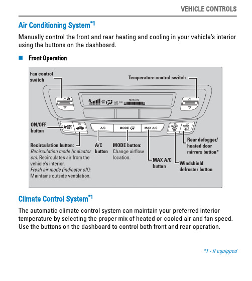
VEHICLE CONTROLS Air Conditioning System*1 Manually control the front and rear heating and cooling in your vehicle’s interior using the buttons on the dashboard. n Front Operation
n Heated Windshield Button*4 Turn the vehicle on. Press the heated windshield button to de-ice the windshield.
*4 - Canadian models only, if equipped
VEHICLE CONTROLS The heated windshield may automatically activate whห้องสมุดไป่ตู้n the outside temperature is below 4°C, and deactivate when the temperature reaches 6°C. n Heated Steering Wheel*1 Press the button to heat the steering wheel when the vehicle is on. Press the button again to turn off the heating.
变频器说明书

U1
1
上海煤科实业有限公司
12
按钮
/
SB1-SB3
3
13
转换开关
LW12-16F/4.5447.2
SW1
1
上海核工双虹电器控制
有限公司
14
转换开关
LW12-16D/4.0518.2
SW2
1
上海核工双虹电器控制
有限公司
15
二极管
FR107
D1-D8
8
深圳市德昌电子有限公司
九、变频器保护功能及故障分析与处理
三、硬件说明
1.外壳结构
a..变频器的隔爆箱外形为直式长方体,上面是接线腔,下面是箱体。箱体内装有变频器功率器件、功率驱动板等器件。接线腔内有12个主接线柱分为两组,A、B、C进线及U1、V1、W1、U2、V2、W2、U3、V3、W3出线,另外还有6个七芯接线柱用来外接传感器信号和远控及工作状态信号,其中4个为本安接线端子。变频控制箱的后侧装散热组件。
2.变频器有两种控制方式:V/f控制和矢量控制
V/f控制方式多用在水泵、风机等不需要很大的起动转矩的场合。
矢量控制多用在提升机、皮带等重载起动,需要很大的起动转矩的场合。
3.保护
下述各种保护,其中任意一种保护动作都可使变频器关断输出,从而保护变频器和电机。
1.过压、欠压
2.过流
3.短路
4.缺相
5.接地
4.端子和导板的连接,请使用接触性好的压接端子。为了防止触电、火灾等灾害事故和降低噪音,必须连接接地端子。接地电缆面积不得小于25平方毫米。
5.接线完毕,请再次检查接线是否正确,有无漏接,端子和导线间是否短路或接地。
6.安装时的所有系统连线必须采用对称性屏蔽电缆,电缆的两端要可靠接地,动力电缆和控制电缆必须分开至少10cm以上,若必须交叉,则动力电缆和控制电缆需垂直布置
变频电机说明书
YTB-S2系列交流电机变频调速器使用说明书概 述YTB-S2系列变频器是我公司在YTB-S1的基础上改进而来,它保持了原有的优点,改善了运行性能, 增加了直流制动功能,及其它附属功能. 使调速更可靠,应用更广泛.,采用先进的SMD 工艺,严格的出厂质检,能够满足用户的多种使用要求.开 箱 检 查1 确认在运输过程中是否造成损坏。
2 检查变频器的铭牌以确定在您手中的产品就是所订货品。
3 检查包装箱内含变频器本体一台,使用说明书一份,出厂合格证一张及其它选购品。
型 号 说 明输出功率容量(KW)输入电压(V)T:三相输入 S:单相输入YTB-S2-1.5/220产品系列名称二次改型技 术 参 数额定功率(KW ) 额定电流(A )S2系列 (单相220V)0.4 30.75 41.5 7.5T2系列(三相380V)0.75 2.5 1.5 3.7 2.2 5 3.7 8.5 5.5 13 输入电源要求 1Φ 220VAC 或 3Φ 380VAC , 50HZ/60HZ 控 制 特 性频率范围0-120HZ 环境 场所 室内无腐蚀气体,无导电尘埃,通风良好 频率设定 按键,外部电位器,0-10mA 输入温度/湿度 -10℃~+40℃ ,相对湿度90%以下,无结露 点动频率0.1-10.0HZ 标高/振动 海拔1000米以下,振动0.5G 以下 制动功能 再生制动, 能耗制动 过载能力 150%,60秒 加减速时间 0.1-120.0秒 显示 四位数码管,显示运行频率、故障代码等 保护功能 过电压,欠电压,过电流 ,过负载、过热保护,失速保护,熔断器保护 冷却方式 自冷/风冷附加功能 定时器/计数器功能安装与结构1. 安装为了提高散热效果,应垂直安装变频器, 安装底板应为铁质或为其它阻燃耐热材料,并留有足够的 通风空间(周围至少留有12CM 以上的空间). 2.接线图1:安装尺寸图铭牌“Mode”--模式键接线盖板图2:操作面板图“▼”--下降键“▲”--上升键“Run”--运行键“Stop”--停止键四位数码管外接型外接操作盒插座普通型正转灯反转灯打开接线盖板,即可看到主接线柱和控制用接线柱。
变频环保空调控制器说明书

变频环保空调控制器说明书变频环保空调控制器说明书1. 产品介绍1.1 产品概述本产品是一种采用变频技术的空调控制器,旨在提供更高效、更节能的空调控制方案。
1.2 产品特点- 采用变频技术,调节空调压缩机运行频率,实现节能效果- 支持多种工作模式,如制冷、制热、除湿等- 具备智能控制功能,可根据环境温度和湿度自动调整空调的运行状态- 能够监测空调系统的运行状态,并提供故障诊断功能 - 具有远程控制功能,用户可通过方式或电脑进行远程控制2. 产品安装2.1 安装前准备在安装之前,请确保以下准备工作已完成:- 选择合适的安装位置,确保空调控制器与空调设备之间的连接线路畅通- 检查控制器及相关配件是否齐全,如遥控器、传感器等- 确保电源线接触良好,无松动和损坏2.2 安装步骤1. 将空调控制器固定在适当的位置上,如墙面或天花板上;2. 连接空调控制器与空调设备的电源线;3. 配置遥控器并将其与空调控制器进行配对;4. 安装传感器,并将其与控制器进行连接;5. 接通电源,并进行相关设置和测试。
3. 产品使用3.1 基本操作本产品支持多种操作方式,如遥控器操作、按键操作等。
具体操作方式请参考产品附带的用户手册。
3.2 功能设置可通过遥控器或其他操作方式对空调控制器的功能进行设置,如温度设定、开关机控制、风速调节等。
3.3 故障排除如果在使用过程中遇到故障或异常情况,请先查看产品附带的故障排除指南进行排查。
如问题无法解决,请联系售后服务人员。
4. 附件本文档附带以下附件:- 用户手册:详细介绍产品的使用方法和功能设置方式。
- 遥控器说明书:介绍遥控器的操作方式和注意事项。
5. 法律名词及注释- 变频技术:一种通过控制电机运行频率来调整其输出转速的技术。
- 节能效果:指通过采用先进技术和措施,实现能源的高效利用,从而减少能源消耗。
- 智能控制功能:指系统具备自动感知环境变化并作出相应控制的能力。
- 故障诊断功能:指系统能够自动检测和诊断故障,并提供相关的故障信息。
变频器说明书大全
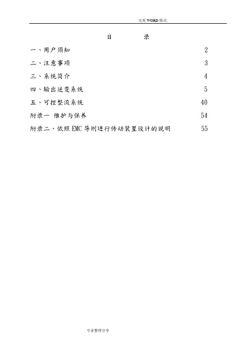
目录一、用户须知 2二、注意事项 3三、系统简介 4四、输出逆变系统 5五、可控整流系统 40 附录一维护与保养 54 附录二、依照EMC导则进行传动装置设计的说明 55一、用户须知1.1该变频调速装置为电力电子器件组成,在运输及安装过程中,尽量避免强烈的震动,尽量垂直运输。
1.2该变频调速装置尽量安装在干燥通风的区域,变频器的散热片距墙壁(或遮挡物)距离应大于1.0米。
1.3长期不用时,应存放在清洁干燥的地方;在井下安装好而不运行的状况下,该设备尽量不停电。
1.4 使用之前,必须详细阅读用户手册。
二、注意事项2.1变频调速装置其隔爆外壳体及本安控制盒的结构和非本安及本安电路的电气参数,在出厂前均已装配调试合格,用户严禁改动变频调速装置壳体的结构和电气参数,以确保本产品的防爆性能、电气性能和本安性能。
2.2设备在带电情况下,严禁松动隔爆壳紧固件,在检修或处理故障时,请注意“断电源后开盖”。
(注:本安接线腔不受此限制)2.3外壳应接地良好。
2.4电源接线隔爆腔在接线时请注意按图接线,不得接错。
2.5装置防爆主腔内进行操作时,手上必须带接地导线或静电环。
2.6装置电源R、S、T停电以后5分钟内禁止对变频器隔爆主腔内的任意电路进行操作,且必须用仪表确认机内电容已放电完毕,方可实施机内作业。
停电以后1分钟内禁止再次给电。
2.7负载运行过程中尽量减少瞬时停电次数。
2.8禁止对变频器主回路及控制回路进行耐压试验,如对与变频有电路联系的相关设备进行耐压试验之前应将与变频相关的电路切断。
2.9测量变频器输出电压时必须使用整流式交流电压表,使用其它非整流式电压表测量高频脉冲电压时,容易产生误操作或显示不准确。
2.10变频器安装应远离大容量变压器及电动机(容量为变频器的10倍以上)。
2.11该系统输出端不可以加装进项电容或阻容吸收装置。
2.12该系统变频器箱与电抗器箱连接必须完全按照相关图纸,以保证反馈电压相序一致。
变频器说明书.doc
——————————————————————————————————————————————注意事项:为了避免触电危险,在对变频器进行任何操作之前确定母线电容的电压已经放尽。
测量电源端子排上DC-和DC+端子上的直流母线电压(参阅第1章电源端子描述)。
电压必须为零。
LED指示灯不亮并不表明电容器已经放电到安全电压等级。
注意事项:只有熟悉变频器和相关机器的合格技术人员才能操作系统的安装、启动和后续维护。
否则,可能导致人员伤害或设备损害。
注意事项:此变频器包含了ESD(静电放电)敏感零件和设备。
当安装、测试、维护或修理这些设备时,应设有静电控制预防措施。
如果不遵守ESD的控制措施,可能引起部件的损坏,参阅国家标准。
注意事项:任何不正确的使用或安装变频器可能会导致损害或降低其使用寿命。
任何接线或其它应用中出现的错误,例如电动机容量和变频器容量不匹配,交流输入电压不正确或不充足、周围环境温度过高可能导致系统的误操作。
注意事项:母线调节器功能对于防止过大减速、过分卸载和偏心负载而引起的过电压故障非常有用。
然而,它会引起以下情况中的一个:1.快速增加输入电压或不平衡的输入电压会引起不受控制的加速;2.实际减速时间可以比命令减速时间长然而,变频器在该状态下保持1分钟将产生“失速故障”。
如果该状态不被确认,母线调节器将被禁止。
另外,安装型号合适的动态制动电阻可以在大多数情况下提供等效或更高的效果。
目录号说明额外附件,可选件和适配器同样可以使用。
详细信息参阅附录B。
变频器额定值目录号框架大小尺寸规格W×H×D输入电压千瓦(kW)马力(HP)输出电流(A)面板安装240V 50/60Hz 1- 相0.75 1 4.2 HPVFE02S0D75 A72×185.5×1461.5 2 8 HPVFE02S1D5 B100×174×146.52.2 3 11 HPVFE02S2D2240V 50/60Hz 1- 相带有内部EMC滤波器0.75 1 4.2 HPVFE02S0D7501 A72×185.5×1461.5 2 8 HPVFE02S1D501 B 100×174×146.52.2 3 11 HPVFE02S2D201240V 50/60Hz 3- 相0.75 1 4.2 HPVFE02T0D75 A 72×185.5×1461.5 2 8 HPVFE02T1D52.2 3 12 HPVFE02T2D2 B 100×174×146.53.7 5 17.5 HPVFE02T3D75.5 7.5 25 HPVFE02T5D5 C 130×258×189.8 7.5 10 33 HPVFE02T7D5460V 50/60Hz 3- 相0.75 1 2.5 HPVFE04T0D75 A 72×185.5×1461.5 2 4.2 HPVFE04T1D52.2 3 6 HPVFE04T2D2 B 100×174×146.53.7 5 8.7 HPVFE04T3D75.5 7.5 13 HPVFE04T5D5 C 130×258×189.8 7.5 10 18 HPVFE04T7D511 15 24 HPVFE04T11460V 50/60Hz 3- 相有内部EMC滤波器0.75 1.0 2.5 HPVFE04T0D7501 A 72×185.5×1461.52.0 4.2 HPVFE04T1D5012.23.0 6.0 HPVFE04T2D201 B 100×174×146.53.7 5.0 8.7 HPVFE04T3D7015.5 7.5 13.0 HPVFE04T5D501 C 130×258×189.8 7.5 10.0 18.0 HPVFE04T7D50111.0 15.0 24.0 HPVFE04T1101第1 章安装/ 接线本章提供HPVFE 变频器安装和接线的信息。
变频器使用说明书
变频器使用说明书一、前言尊敬的用户,欢迎您使用本款变频器。
本变频器是一种能够实现电机调速的先进设备,广泛应用于工业生产、自动化控制等领域。
为了确保您能够安全、有效地使用本变频器,请在使用前仔细阅读本使用说明书。
二、产品概述1、变频器的定义与作用变频器是一种通过改变电源频率来控制交流电机转速的电力电子设备。
它可以实现电机的无级调速,提高电机的运行效率,降低能耗,延长电机的使用寿命。
2、本变频器的型号与规格本变频器的型号为_____,适用于功率范围为_____的交流电机。
其输入电压为_____,输出频率范围为_____。
3、主要特点高精度调速:能够实现精确的转速控制,满足各种工艺要求。
节能效果显著:通过优化电机运行,有效降低能源消耗。
多种保护功能:具备过流、过压、过载、短路等保护,确保设备安全运行。
操作简便:配备直观的操作界面,易于设置和调试。
三、安装与接线1、安装环境要求温度:变频器应安装在环境温度为_____的场所,避免阳光直射和高温环境。
湿度:相对湿度应控制在_____以下,无凝露。
通风:确保安装场所通风良好,以利于变频器散热。
2、安装方式壁挂式安装:将变频器固定在垂直的墙壁上,保持水平。
机柜式安装:将变频器安装在标准机柜中,注意机柜的尺寸和通风条件。
3、接线注意事项输入电源接线:务必按照变频器上的标识连接正确的电源相序,确保电源电压符合要求。
电机接线:将电机的三相绕组与变频器的输出端正确连接,注意接线的紧固和绝缘。
控制信号线接线:根据控制要求,连接好调速信号、启停信号、故障信号等控制线,确保信号稳定可靠。
四、操作与显示1、操作面板介绍显示屏:用于显示变频器的运行参数、状态信息和故障代码。
按键:包括启动/停止键、调速键、功能选择键等,用于设置和操作变频器。
2、基本操作步骤上电:接通电源后,变频器进行自检,显示屏显示初始状态。
启动:按下启动键,变频器驱动电机运行。
调速:通过调速键或外部调速信号,调整电机的转速。
ATV 11 异步电机变频器 说明书
ATV 11pppppp A V1.2 IE ≥21 ATV 11ppppppE327
用户手册
目录
设置变频器步骤 ............................................................................................................................................................2 出厂设置 .......................................................................................................................................................................... 2 尺寸 ...................................................................................................................................................................................2 安装和温度条件 ............................................................................................................................................................3 接线端子 .......................................................................................................................................................................... 4 接线图 ..............................................................................................................................................................................5 显示屏和按键功能 ........................................................................................................................................................ 6 调整参数......................................................................................................................................................................... 7 模拟输入菜单 AIt ......................................................................................................................................................... 8 电机控制菜单 drC.........................................................................................................................................................9 应用功能菜单 FUn..................................................................................................................................................... 10 显示菜单 SUP............................................................................................................................................................. 15 故障 - 原因 - 解决办法............................................................................................................................................. 16 显示故障....................................................................................................................................................................... 17
空调系统操作维护手册
空调系统操作维护手册1. 简介空调系统是一种用来调节室内温度、湿度和空气质量的设备。
本手册将介绍如何正确操作和维护空调系统,以确保其正常运行和长久使用。
2. 操作指南2.1 开关机操作在使用空调系统之前,确保电源已经连接,并且空调系统已正确安装在墙壁或天花板上。
按下电源按钮即可开启空调系统,再次按下则可以关闭。
务必在使用完毕后关闭空调系统,以节省能源并延长设备寿命。
2.2 温度调节使用空调系统控制面板上的温度调节按钮,您可以调整室内温度。
一般来说,合适的室内温度范围在22°C至26°C之间。
调整温度时请考虑到室内外温差,以避免身体不适。
2.3 模式选择空调系统通常具备多种模式选择,如制冷模式、制热模式、通风模式和除湿模式。
根据不同的季节和需求,选择合适的模式以调节室内环境。
2.4 风速调整控制面板上的风速调节按钮可用于调整空调系统的送风速度。
一般来说,高风速适合迅速降低室内温度,而低风速适合保持室内舒适。
2.5 定时开关机大部分空调系统具备定时开关机功能,您可以根据需要设定特定的开关机时间。
这对于提前预热或定时关闭空调系统非常有用。
确保正确设置定时器以避免能源浪费。
3. 维护指南3.1 定期清洁空调系统定期清洁空调系统是确保其正常运行的关键。
可以使用吹风机或吸尘器清除空调系统的进气口、出气口和滤网上的灰尘和杂物。
请务必在清洁空调系统之前拔掉电源插头。
3.2 更换滤网空调系统中的滤网起到过滤空气并防止灰尘进入系统的作用。
长时间使用后,滤网会积累大量灰尘,影响空调系统的效果。
根据使用频率和环境条件,建议每隔一到三个月更换一次滤网。
3.3 定期维护建议定期请专业维修人员对空调系统进行维护,以确保其正常运行。
维修人员将会清洁空调系统内部的部件、检查易损件是否需要更换,并调整系统以提高效率。
3.4 注意安全在操作空调系统时,请务必注意安全。
避免触摸空调系统的内部零件以防止受伤。
不要在开启空调系统后立即更改温度,以免因温差过大而导致不适。