门径管理概要 Stage Gate
产品创新管理方法
主要描述
主要优点
主要不足
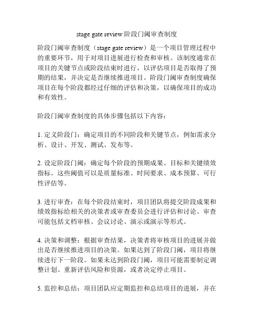
门径管理方法
(Stage-Gate System,SGS)
门径管理体系用于管理、引导并加速产品创新活动。门径管理流程是由加拿大麦克马斯特大学库珀教授最新提出的,该流程为近80%的北美企业所采用。门径管理方法把产品创新流程划分成一系列预先设定的阶段,每一个阶段由一组预先规定的、跨职能的、同时进行的活动组成。
缺乏系统的理论总结和提升
公开资料少,不便于学习和应用
集成产品开发管理方法
(Integratede Product Development,IPD)
/
源于PACE方法,是IBM自身新产品开发实践的总结,聚焦于流程改进。在华为公司有应用。
系统、详细
过于复杂,缺乏灵活性,中小型企业难以应用。
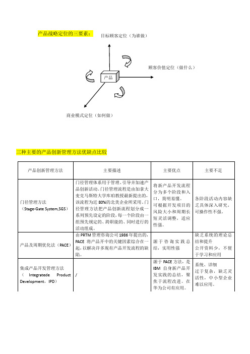
ห้องสมุดไป่ตู้产品战略定位的三要素:
2
创新
新产品、新服务开发目标,技术开发目标,基础研究目标,商业模式创新目标,运营创新目标。
3
人力资源
管理人员的供应、开发和工作绩效目标,非管理岗位人员的供应、开发和工作绩效目标,员工态度和技能目标,企业与工会关系目标。
4
资本资源
融资目标,上市目标
5
物质资源
原材料供应目标,零部件供应目标,机器设备目标,办公场地目标
将新产品开发流程分为多个阶段和入口,简明易懂。
可根据开发项目的风险大小和周期长短灵活调整,适应性强。
各阶段活动内容缺乏具体深入研究,可操作性不强。
产品及周期优化法(PACE)
由PRTM管理咨询公司1986年提出的,PACE将产品开中的关键因素综合在一起,以解决许多现有产品开发流程的缺陷。
源于咨询实践总结,实用性强
stage gate review 阶段门阈审查制度
stage gate review 阶段门阈审查制度
阶段门阈审查制度(stage gate review)是一个项目管理过程中的重要环节,用于对项目进展进行检查和审核。
该制度通常在项目的关键节点或阶段结束时进行,以评估项目是否取得了预期的结果,并决定是否继续推进项目。
阶段门阈审查制度确保项目在每个阶段都经过仔细的评估和决策,以确保项目的成功和有效性。
阶段门阈审查制度的具体步骤包括以下内容:
1. 定义阶段门:确定项目的不同阶段和关键节点,例如需求分析、设计、开发、测试、发布等。
2. 设定阶段门阈:确定每个阶段的预期成果、目标和关键绩效指标。
这些阈值可以是质量标准、时间要求、成本预算、可行性评估等。
3. 进行审查:在每个阶段结束时,项目团队将提交阶段成果和绩效指标给相关的决策者或审查委员会进行评估和讨论。
审查可能包括文档审核、会议讨论、演示或演示等形式。
4. 决策和调整:根据审查结果,决策者将审核项目的进展并做出是否继续推进项目的决策。
如果达到了阶段门阈,项目将继续进行下一阶段。
如果未达到阶段门阈,项目可能需要制定调整计划、重新评估风险和资源,或者决定停止项目。
5. 监控和总结:项目团队应定期监控和总结项目的进展,并在
每个阶段结束时对项目的成功与失败进行评估和总结,以便在将来的项目中获得经验教训和持续改进。
阶段门阈审查制度在项目管理中起着重要作用,可以提高项目决策的明确性、减少风险、优化资源配置,从而提高项目的成功率和效率。
零部件初期流动管理
挑战目标2项以下(包括2项); 挑战目标4项以下(包括4项); 挑战目标5项以上(包括5项);
2、无永久对策或永久对策无效 2、主要不具合课题中,无永久 2、主要不具合课题中,无永久
果的课题为0;
对策或永久对策无效的课题占总 对策或永久对策无效的课题占总
3、在新车项目完了会中,由本 课题的10%以下 ;
QG-14 QG-15~20
3
初期流动管理的时机
量产(初期管理)阶段(QG-15~20)
① 初期管理
虽然工序准备和量产试行(HVPT)时,进行了一定数量的 生产;但是还远不能了解真正大批量生产时会发生什么事 。因此,设定一定的期间,进行检查项目、确认频度等方 面的特别管理,也就是所谓的初期管理。
日程
2、品质问题汇整回馈,阻 留车掌握,低减推动
1、会同开发、生管、采购 推动4M+Q 特管; 2、主要问题点厂商改善 F/U及小量产品确; 3、试装问题及线上问题改 善推动; 4、影响量产重大问题事前 防止拟定; 5、常发问题防呆推动
1、试装问题改善后的进 料检验管制。 2、线上问题点处理及回 馈改善; 3、线上问题点的进料品 质管制; 4、来件不良调查解析
6
特管体制实施
7
售服市场品情跟踪
担当 车品组 车品组 车品组 装配组 零品组 车品组 品保组
频度 2H/次 每日1回 1回/2周 每日 按需 PP/MP 每日1回(3个月)
地点 车品漏水棚旁 生产部会议室(一) 品管部会议室(一) 生产部会议室 品管部会议室(二)
—— 品管部会议室(一)
严密规划 认真执行 确保品质
XXX(晚班) XXX(晚班) XXX(晚班) XXX(晚班) XXX(晚班) XXX(晚班)
克莱斯勒开发系统质量门

V
问题?
CDS 接收标准 S,C 问题?
CDS 接收标准
V
问题?
PAP4CDS=CDS 产品保证计划
LSSS LSSS LSSS SSSS SSSS SSSS
SSSS SSS
产品规划 设计 先期车辆工程 产品开发与质量 产品制造工艺 生产制造 采购与供应 全球销售与市场 财务 共同的质量 产品服务策略 ITM 其他
6
克莱斯勒开发系统
图示 6:质量门评估问题和责任矩阵 质量门评估
质量门 X
质 量 门 交付物/接收标准
PAP4CDS
分类
任务号
质量门
描述
1. CDS 交付物
PAP 任务
CDS 接收标准
V
问题?
CDS 接收标准
V
问题?
2. CDS 交付物
PAP 任务
CDS 接收标准
分类 V
问题?
CDS 接收标准
V,S,C 问题?
CDS 质量门原则 戴姆勒.克莱斯勒“阶段门”系统把产品开发过程分成一系列预定的阶段,每一阶段包含一组预定 的、多功能的、平行的活动。进入各阶段有一个阶段门:这些阶段门控制着产品开发过程并为质量 控制提供检查点:通过、不通过或需修正计划通过。 图示一:质量门流程图示例
CDS 质量门原则: 质量门是执行委员会级别,多功能的评审。 假如质量门通过,计划将如期执行。 质量门按如下设 想管理: 1) 有一个 CDS 质量门过程。 2) CDS 和质量门由顾客驱动。 3) 质量门是整体的,即他们控制从构思阶段到投放市场的全过程,不仅是开发阶段。 4) CDS 要求先期的或预开发工作——构思、产品战略开发、技术管理及组合管理。所有必要的
工作应在每个门之前完成。 5) 质量门是多功能的。产品设计、市场营销、制造、采购、工程、财务等都是产品组的完整部分。 6) 质量门评审由首席工程师和/或产品核心组领导者一起领导。 7) 质量门或决策点也是多功能的,项目干系人和资源经理也在其中。 8) CDS 质量门要求并行或同时处理,不是连续的。 9) CDS 各质量门要求清晰的交付物和标准。 10) 质量门信息的透明确保所有的功能(实体)和级别(组织)都有机会获得同样的信息。 11) 质量门评审建立在风险评估之上,其风险取决于计划的级别。
管理方格理论

尽管布莱克和莫顿信心十足,但是,他们的最优化设计能否在理论上把权变理论排挤出管理学阵地,似乎并 不乐观。在《新管理方格》的论述中,布莱克和莫顿虽然不承认权变理论的合理性,但却不得不在一定程度上承 认权变理论的现实性。在他们的理论推导中,也小心翼翼地避开了西蒙的有限理性学说。既然他们强调自己提出 的(9,9)型团队管理具有最优性,那就必须证明这一模式已经克服或战胜了对人类理性的各种限制。这种回避, 显露出了他们的理论软肋所在。
阶段4:设计理想的战略组织模型,要明确确定最低限度的和最优化的公司财务目标,在公司未来要进行的经 营活动、要打入的市场范围和特征、要怎样创造一个能够具有协力效果的组织结构、决策基本政策和开发的目标 等方面有明确的描述,以此作为公司的基本纲领,作为日常运作的基础。
阶段5:贯彻开发。
起源介绍
管理方格理论来源于领导方式双因素理论。
管理方格理论提供了一个解析管理行为的理论框架,现实中的管理活动不完全是上述五种类型的纯粹形态, 而是这五种类型的混合体。我们可以运用管理方格理论的不同组合方式,来认知现实中的管理类型。常见的管理 类型组合有以下几种。
家长作风。家长作风是权威型管理同乡村俱乐部型管理的第一种组合,既具有(9,1)型的强制,又具有 (1,9)型的体谅。这种领导人会把他麾下的组织当做一个大家庭,对部属兼具“严父”和“慈母”两种身份。 比如,他可以毫不留情地训斥某个工人,但当这个工人下班时,他又会递上一支烟,对他表示出真诚的关心。他 常常鼓励部下要负起责任,但又不会真正放权。比如,他会对副手说:“你就不能胆子大一点?这样下去怎能成 就大事?”但副手一旦自作主张违反了他的意图,则会遭到他毫不留情的批评。“叫你胆大也要看是什么事,这 么重要的事你怎能自作主张?”正是这两种风格的组合,会使部属陷入不确定性的泥沼,部属只能私下揣摩,把 握不准就只好请示汇报。而这种请示又可能招致胆小怕事的训斥。部属在这种情况下,就会逐渐形成唯唯诺诺的 习惯,还有可能退缩到不求有功、但求无过的贫乏型管理。凡是抱怨部下缺乏主动性和积极性的领导人,都有必 要从自己身上找找原因。从历史上看,仁慈开明的君主,坚韧而又执著的传教士,都能反映出这种管理风格。
Runnerandgatedesign:流道和浇口的设计

Runner and gate design.The Important FeaturesIntroduction;The following is a brief summary of the important factors to consider when designing runner and gating systems for Zinc and Aluminium pressure die casting dies.In the past runner systems were designed using empirical knowledge and developed using trial and error methods which involved excessive time and often multiple die trials. Today, computer programmes exist which eliminate these problems and are able to give good results immediately but, many of the most basic design issues are often neglected during the design stage particularly if the die is designed by the tool maker without consultation to the die casting technicians.These brief notes are intended as guidelines for use during training and as an aide memoiré for die design technicians and designers. They are not intended to cover all aspects of die design practice.____________________________Objective:The runner and gate system should achieve the following in basic terms:•Produce a casting of the specified quality; in terms of finish, size and tolerance, casting integrity, mechanical properties, cycle time and consistency.••Achieve first time success; to avoid wasted time on successive machine trials, delays in delivery of samples, loss of customer confidence and excessive die developmentcosts.••Provide optimum yield; increases efficiency by optimising the casting to runner yield ratio, improve metal losses due to lower re-melt weights, reduces cycle times due toimproved thermal efficiency.THE BROCK METAL COMPANY LIMITED,WALSALL ROAD. NORTON CANES, CANNOCK, STAFFS, UK WS11 9NR.Runner and gate design.Influencing factors.Designing a runner system:Selection of the machine should be based on several factors but not just shot weight and platen area. Most machines are supplied with a PQ2 diagram or one exists from measurements taken on other similar machines. Runner designs should be based on machine performance with a given plunger or shot sleeve diameter, known hydraulic pressure and in the case of hot chamber die casting the nozzle size. Both projected area and lock tonnage should also be considered if the proposed runner plus casting is liable to approach the machine limits.Casting geometry:The cavity should be positioned to promote the best cavity fill conditions while accommodating essential die features such as core slides, cooling channels, sensitive casting features, number of cavities and robotic removal constraints. Other process criteria such as second operation locations, clipping orientation, break off de-gating and finishing requirements should also be considered before the cavity position is decided.Uniform flow path:The runner should establish a uniform metal flow rate deigned to promote the best hydraulic system, stable metal pressure and velocity. Most computer design programmes will control these features but the designer will still have institute a flow path allows these features conform to the desired parameters.Cavity fill conditions:Modern pressure die casting machines often have more power at the shot end than is required to achieve the optimum fill conditions. Consequently, the performance offers many gate area options capable of achieving the desired fill conditions – the designer must select the most suitable based on the casting specification and process limitations.Cavity fill pattern:Is invariably decided by the casting geometry and gate position but the metal pressure and velocity will have influence but to a lesser extent. The influence of casting features such as vertical surfaces and ribs, variable section thicknesses, isolated bosses and cores must be considered when the gate position is decided.Venting and overflow wells:Should all be considered at the design stage – are directly related to the cavity fill conditions and casting geometry but also the introduction of over flow wells or pockets may have significant cost implications.THE BROCK METAL COMPANY LIMITED,WALSALL ROAD. NORTON CANES, CANNOCK, STAFFS, UK WS11 9NR.Runner and gate design.Machine Performance.Effects of change.Injection pressure: Reduce or increase .• Increased injection pressure – will increase flash, raise galvanising and die erosion.Optimum pressure levels will improve casting integrity, maintain speed and velocity and improve cavity fill conditions.Reduced injection pressure – reduces flow rates, and static metal pressure on hot chamber pressure die casting machines.• Plunger diameter – on hot chamber die casting machines smaller plungers give thebest casting results with higher injection pressure and faster delivery. On aluminium cold chamber machines plunger diameter choice is less critical but effect is far more significant in performance terms - increasing delivery velocity and reducing cavity fill times.• Plunger speeds - high terminal velocities can produce pressure spikes on older diecasting machines leading flash and die wear. High gate speeds result in expensive die maintenance due to die erosion and galvanising.• Runner Area/volume - die designer should create a uniform flow through the runnerby establishing nozzle area (hot chamber) as the largest section in the runner.Progressively reducing the cross sectional area of the runner at each section to the gate which should be the smallest area in the runner system. Similarly, on cold chamber dies the sprue post runner should be the largest runner section down to the gate which should be smallest section of the runner.Flow rate histogram.N o z z l e a r e aGateAreaTHE BROCK METAL COMPANY LIMITED,WALSALL ROAD. NORTON CANES, CANNOCK, STAFFS, UK WS11 9NR.Runner and gate design.Runner features‘Y’ Junction not ‘T’‘Y’ JunctionReduces area and increases pressure progressively.‘T’ JunctionIncreases volume at the junction creating low pressure area at the centre of the gate.THE BROCK METAL COMPANY LIMITED,WALSALL RO D. NORTON CANES, CANNOCK, STAFFS, UK WS11 9NR.ARunner and gate design .Runner featuresTaper tangential runner - with shock absorber – showing section change A to B toSmaller diagram – illustrates poor runner design small access radius,increased e taper,maintain pressure and velocityrunner volume at the radius, small runner cross section at the end of th and no shock absorber.THE BROCK METAL COMPANY LIMITED,WALSALL RO D. NORTO NES, CANNOCK, STAFFS, UK WS11 9NR.A N CARunner and gate design .Runner featuresDrawings – Show section through sprue posts on Aluminium (top ) and Zinc (bottom )This area most commonly inte d incorrectly by toolmakers.Note; Th radiusdies.rprete e reduction from the sprue faces to die face and the size and blend which are struck from the same centre to ensure even transition from sprue to die.THE BROCK METAL COMPANY LIMITED, WALSALL ROAD,. NORTON CANES, CANNOCK, STAFFS, UK WS11 9NR.Runner and gate design .Runner featuresRunner sections: Need to be adjusted by differing percentages tor l10% reduction in runnerarea- down stream of metalaccommodate larger angular direction changes30% reduction in runner a ea - down stream of meta flow – for 900 bend.flow – for a 200 bend.THE BROCK METAL COMPANY LIMITED, WALSALL ROAD. NORTON CANES, CANNOCK, STAFFS, UK WS11 9NR,Runner and gate design .Gate Areasate Areas:ptimum for Zinc alloy pressure die-casting :ed / velocity – 35 – 45 metres per second.ish – 20 milli seconds or functionalOptimum for Aluminium alloy pressure die casting:5 metres per second..ortant on large castings asFil a etry: has the largest influence on cavity flow paths – high metal velocitypplied to vertical casting faces causes turbulence, galvanising and impedes metal. All of which and areas; It is possible to assess parts of the casting separately nd this may be advantageous if they are unlikely to be fed directly from the gate. of a given part sing separate gates for each zoned area. This will often improve fill characteristics low: It must be stressed that the gates and runner both fluence flow direction. Once the runner is established metal under pressure will G O • Gate spe • Cavity fill time – plated or powder coated fin parts – 40 milli seconds.• Gate depth – 0.15 – 0.5 mm.• Gate speed / velocity – 25 to 3To avoid die erosion and control cavity fill characteristics • Cavity fill time – end of fill temperature is most imp solidification can occur prior to cavity filling.• Depth 1.25 – 3 mm (1.5 mm minimum for machine intensification to be effective ).l P ttern:Casting geom a can result in expensive die repairs / maintenance. Section changes and cores change pressure and direction and these effects need to be considered and understood when considering gate position options.Zones volumes a Using computer programmes allows each separate zone to be quantified in volume and surface area terms. If treated as un-gated the fill time and end of fill temperature can be determined as a comparison with the main body of the total casting.Gating separate zones: It is possible also to examine separate zones u and reduce the risks of defects. The uses of multiple gates are not a risk if designed and implemented correctly.Runner will direct metal f in enter the cavity in the same direction and flow angle. Varying injection speed and metal pressure may alter this angle slightly but this is only a fine tuning method.THE BROCK METAL COMPANY LIMITED, WALSALL ROAD. NORTO NES, CANNOCK, STAFFS, UK WS11 9NR,N CARunner and gate design .Fill pattern.Influence of casting geometry ertain casting shapes are best filled in a predetermined way, if the toolingre the depth is 50% of the edge length or more he box :C configuration allows. Deep boxes, whe can be fed using the gate runner configuration shown below – alternatively t can be turned through 450 to shorten the runner distance and improve shot yield.THE BROCK METAL COMPANY LIMITED, WALSALL ROAD. NORTON CANES, CANNOCK, STAFFS, UK WS11 9NR,Runner and gate design .Fill pattern.vals or round castings: Try to fill the centre first using either a runneronfiguration below or a more traditional fan feed. With fan feeds it is essential to getO c the ratio of the approach angle and width of gate correct.THE BROCK METAL COMPANY LIMITED, WALSALL ROAD. NORTON CANES, CANNOCK, STAFFS, UK WS11 9NR,Runner and gate design .Fill pattern.nnular rings: Can be fed using the runner configuration indicated below. A smallver flow well should positioned in the centre hole to take away any lubrication fume A o and another well placed on the out side perimeter adjacent to the last segment of the part to fill.THE BROCK METAL COMPANY LIMITED, WALSALL ROAD. NORTON CANES, CANNOCK, STAFFS, UK WS11 9NR,Runner and gate design .Fill pattern.Rectangular Plates: Fill across shortest distance whenever possible – t cut downow distance and increase end of fill temperature. It is therefore advisable to avoido fl the option shown in the upper diagram if possible.THE BROCK METAL COMPANY LIMITED, WALSALL ROAD. NORTON CANES, CANNOCK, STAFFS, UK WS11 9NR,Runner and gate design .Fill pattern.Diagram show e – to resolve problems ofporosity and poor ximately 6 mm deep, with a gate depth of between 1.8 and 2.5 mm. Casting weighed approximately 5 Kg and with a flow distance of 510 m s: runner developed over a period of tim fill results. The darker blue area is appro m.THE BROCK METAL COMPANY LIMITED, WALSALL ROAD. NORTON CANES, CANNOCK, STAFFS, UK WS11 9NR,Runner and gate design .Fill pattern.Diagram show niform gate thickness of 2 mm. The runner and a subsequent increase in yield of 18% and a reduction in pr ected area of some 22% allowing improved shot speed and increased in injecs: Revised runner with balance fill and u shows reduced shot weight by over 1 Kg oj tion pressure.THE BROCK METAL COMPANY LIMITED, WALSALL ROAD. NORTON CANES, CANNOCK, STAFFS, UK WS11 9NR,Runner and gate design .Vents and Overflow wells.Points to remember:• Over flow w tal flow, but rarely remove gas and fume as the cavity is normal sealed before they become a .only work for less than half of the cavity fill time as they arefinal fill is achieved. • Over flow wells are a poor method of die heating both inefficient and wasteful.See reference material from ILZRO, IZA.JWTSep ells can be used to change or divert mective ly • Similarly vents can sealed off before the• Use only one connection per over flow to avoid back feeding through theoverflow and reintroducing gas and cold metal. • Always vent over flow wells – as a precaution.Many are lost before re-melting and therefore increase metal losses.t 05 – issue 5。
管理方格理论
组织行为学——管理方格理论目录一.管理方格理论.................................... (一)管理方格理论的提出................................ (二)管理方格理论的内容................................ (三)9.9管理方式发展的五个阶段培训..............................(四)“领导”的五种类型及分析.........................(五)管理方格理论的理论意义........................ (六)管理方格理论的实践价值......................... (七)案例分析...................................... 二.路径—目标理论一.管理方格理论(一)管理方格理论的提出管理方格理论(Management Grid Theory)来源于领导方式双因素理论,1945年,俄亥俄州立大学工商研究所的斯托格第尔(RalphM.Stogdill)和沙特尔(CarrollL.Shartle)两人主持了这一研究。
他们把领导行为归纳为“关心人员”(体谅)和“关心工作”(结构)两个方面,每个方面又分为高与低两个区域,并由此设计出了著名的“领导行为”四分图(即高体谅高结构、高体谅低结构,低体谅高结构、低体谅低结构四个象限)。
在此基础上,美国德克萨斯大学的行为科学家罗伯特·布莱克(Robert R·Blake)和简·莫顿( Jane S·Mouton)在1964年出版的《管理方格》一书中提出研究领导方式及其有效性的管理方格理论。
管理方格图的提出改变以往各种理论中“非此即彼”式(要么以生产为中心,要么以人为中心)的绝对化观点,指出在对生产关心和对人关心的两种领导方式之间,可以进行不同程度的互相结合。
C_CTCS_01 全球产品引入管理程序(GDPIM)
1.0 Scope 范围GDPIM is a mandatory process. It is used across all plants, locations and business units within TRW Automotive for the development and introduction of new products and applications.GDPIM是一种强制性经营过程,用于TRW汽车公司内的所有工厂、场所和营业单位开发和引入新产品和新应用。
2.0 Purpose目的The purpose of this procedure is to outline the key elements of GDPIM. GDPIM is the business process used to manage product development and customer application programs. The process consists of defined phases and reviews that cover the product development cycle from concept to production. The process employs cross-functional program management.本程序的目的是概述GDPIM的要素。
GDPIM是一种经营过程,用于管理产品开发和用户应用项目。
该过程包括定义的各个阶段和评审,涵盖从概念到生产的整个产品开发过程。
该过程使用交叉职能项目管理。
3.0 References参考资料GDPIM GlossaryGDPIM术语表B20: Commercial CQA ProcessB20:CQA工业化生产过程A63: GDPIM Program CategorizationA63:GDPIM项目分类A61: GDPIM & Program ReviewsA61:GDPIM & 项目评审4.0 Roles and Responsibilities角色和责任There are four fundamental roles within GDPIM which are defined in the following table.在GDPIM中有四个基本角色,在下表中定义。