JOHANSON规格书JDI_Safety-Caps_
JBC焊台DDE-2A说明书

PageEnglish2Español16Deutsch302 Tools Control UnitRef. DDE-ADDE-A说明书由汉迪丰科技黄新银整理发布DD控制主机可连接管理2个焊具,2个焊具皆可同时工作。
DD可以搭配任何一种焊具,以建立自己的焊接/拆焊工作站。
一个基本的组合型工作机种,你至少需要选择1个焊具座丶1个焊具和1支烙铁芯。
有超过300种烙铁芯可以选择。
DD采用了的JBC独特的加热系统,温度补偿迅速,有效提高工作效率。
智能睡眠和休眠功能延长烙铁芯的寿命达5倍以上。
在机台功能表中,您可以自行编辑20多种功能项目,用以帮助管理焊接工作。
此版本现提供 USB接口 (B型接口), 未来可连接电脑进行软体升级及提供即时温度/功率曲线。
技术资料重量 3.6 kg (7.8 lb)尺寸145x120x225 mm电压230V / 120V / 100V保险丝 2A (230V), 4A (120V and 100V)输出功率150W / 23.5V温度选择范围90-450 ºC / 190-840 ºF接地电阻<2 ohms对地电阻<2mV RMS工作环境温度10-40 ºC / 50-104 ºF防静电USB 连接介包装重量 3.9 kg (8.6 lb)Packing ListThe following items should be included:- 2 Tools Control Unit .............................. 1 unit Ref. DDE-1A (120V)DDE-2A (230V)DDE-9A (100V)- 1.5m Power Cord ................................... 1 unit Ref. 0010569 (230V)0013671 (100/120V)- Manual ....................................................... 1 unit Ref. 0013167Features ConnectionsWork simultaneously with up to 2 tools and 1 module + 1 pedal for each tool (Peripherals).2,8” Color TFT screen with capacitive keyboard Tilt the display foreasy reading USB-AconnectorRef. P-005Control UnitEquipotentialconnectionUSB-BconnectorPower S ocketToolRJ12 connectorfor Robot systemModule cableRef. 0012709Stand PeripheralsTo another peripheralTo PedalStands & ToolsFor a basic working system you need: 1 Stand, 1 Tool and 1 Cartridge or tip.StandsToolsPrecision purposesHandleRef. T210General purposesHandle Ref. T245HD General purposes Handle Ref. T470Nitrogen Handle Ref. T245-NA* Solder Feed Iron Ref. AP130Micro Tweezers Ref. P A120Thermal TweezersRef. HT420Micro Desoldering IronRef. DS360Desoldering Iron Ref. DR560* The MNE Nitrogen Flow Regulator isrequired to work.CartridgesC210C245C560C130Ref. AD-SDRef. DN-SDRef. AP-SDRef. DS-SDRef. PA-SDRef. HT-SDRef. DR-SDC360C120C420PeripheralsBy pressing Peripherals in the main MENU, you can join tool ports with peripherals which means each tool can work with 1 module and 1 pedal at the same time.Control UnitCompatibilitySelect the equipment that best suit your soldering or desoldering needs.Electric Desoldering Module Pneumatic Desoldering Module Ref. MVE-AStickstoff-Mess- und RegelsystemPedal Ref. P-005Fume ExtractorSwitch Ref. FSE-A* The MNE Nitrogen Flow Regulator is required.**If you need to connect the MS, MV, MN or FS modules, an adapter is required (Ref. IM2496).Function: Enable/disable the module or make any tool enter Sleep or Hibernation modes. This pedal will work with any module or tool regardless of the module to which it is connected.If you do not have a module, you can link up the P-305 Pedal Kit to the tool port.P-305 Pedal KitBy using the Connection Box, the P-005 Pedal will work with only the tool port to which it is connected.Function:Makes the tool enter/skip from Sleep mode.Connection Box +Ref. 0012527Tool port connectionPedal Ref. P-005Ref. MNE-ARef. MSE-AOperationThe JBC Exclusive Heating SystemOur revolutionary technology is able to recover tip temperature extremely quickly. It means the user can work at a lower temperature and improve the quality of soldering. The tip temperature is further reduced thanks to the Sleep and Hibernation modes which increase the tip life by 5.Work ScreenThe DDE-A offers an intuitive user interface which provides quick access to station parameters.1. Work2. Sleep3. HibernationStatus 17:14ToolconnectedWhen the tool is lifted from theWhen the tool is in the stand,After longer periods ofPower indicatorlevels arePort 2stand the tip will heat up to the selected temperature.the temperature falls to 180ºC / 360ºF (preset sleep temperature).inactivity (pre-set to 30 min.), the power is cut off and the tool cools down to room temperature.activatedPress INFO for eachparameter description.USBflash drive is connected. Station is controlled by a PC.Station is controlled by a robot.Tools M enu:Tools M enu:Tools Menu:StationToolsCountersStation software update.Press INFO to start the process.· Set temperature limits · Select temperature levels· Set Sleep temperature· Set Sleep delay(from 0 to 9 min or no Sleep)· Set Hibernation delay (from 0 to 60 min or no hibernation)PeripheralsGraphicsResetWarning.Press INFO for failure description.Error. Press INFO for failure description, the type of error and how to proceed.Port 2Port 2HibernationPort 2Long time in the standProcess analysis Soldering NetGraphicsBy pressing Graphics in the main MENU, temperature and power figures in realtime are displayed for each port. This helps you decide which tip to use to obtainthe best quality solder joints.Remotely manage and monitor as many stations as your PC can handle.1. Download the JBC Manager software and the user manual from /manager.html2. Connect the stations via USB-B connector and the PC will automatically detect them.3. The notification will be displayed on the station.Power (%)Functions:- Set all the station parameters from your PC.- Organize groups of stations and set all their parameters at the same time.- Store specific configurations for later uses.- Analyze the soldering graphics of the stations on your PC and export them.See otherport graphicExport graphicsInsert a USB flash drive into the USB-Aconnector to start saving your solderingprocess in csv format.Working with RobotsMaintenanceManage and monitor the station using a Robotic system.Before carrying out maintenance or storage, always allow the equipment to cool.1. Connect the tool to the station port by means of the Converter.2. Connect your Robot system to the Robot connector (RJ12) of the station. DB9-RJ12 Adapater available only if necessary (Ref: 0013772).3. Enable the Robot option in the station settings and the notification will be displayed:4. Set your R obot’s commands according to the Robot Communication Protocol, available on the website /jbcsoftware-menu-115.html.- Clean the station screen with a glass cleaner or a damp cloth.- Use a damp cloth to clean the casing and the tool. Alcohol can only be used to clean the metal parts.Clean periodicallyRobot- Periodically check that the metal parts of the tool and stand are clean so that the station can detect the tool status.- Maintain tip surface clean and tinned prior to storage in order to avoid tip oxidation. Rusty and dirty surfaces reduce heat transfer to the solder joint.Control Unit- Periodically check all cables and tubes.- Replace a blown fuse as follows:Update the station software1. Download the JBC Update File from/software.html and save it on a USB flash drive. Preferably one with no other files.2. Insert the USB flash drive to the station. The icon is diplayed while updating.1. Pull off the fuse holder and remove the fuse. If necessary use a tool to lever it off.2. Press the new fuse into the fuse holder and replace it in the station.- Replace any defective or damaged pieces. Use original JBC spare parts only. - Repairs should only be performed by a JBC authorized technical service.JBC Update FileFuseFuse holderFuse holderSafetySpecifications- Do not use the units for any purpose other than soldering or rework. Incorrect use may cause fire.- The power cord must be plugged into approved bases. Be sure that it is properly grounded before use. When unplugging it, hold the plug, not the wire.- Do not work on electrically live parts.- The tool should be placed in the stand when not in use in order to activate the sleep mode.The soldering tip, the metal part of the tool and the stand may still be hot even when the station is turned off. Handle with care, including when adjusting the stand position.- Do not leave the appliance unattended when it is on.- Do not cover the ventilation grills. Heat can cause inflamable products to ignite.- Use a “non residue ” classified flux and avoid contact with skin or eyes to prevent irritation.- Be careful with the fumes produced when soldering.- Keep your workplace clean and tidy. Wear appropriate protective glasses and gloves when working to avoid personal harm.- Utmost care must be taken with liquid tin waste which can cause burns.- This appliance can be used by children over the age of eight and also persons with reducedphysical, sensory or mental capabilities or lack of experience provided that they have been given adequate supervision or instruction concerning use of the appliance and understand the hazards involved. Children must not play with the appliance.- Maintenance must not be carried out by children unless supervised.Exploded ViewIt is imperative to follow safety guidelines to prevent electric shock, injury, fire or explosion.DDE-1A 120V 50/60Hz. Input fuse: 4A. Output: 23.5V DDE-2A 230V 50/60Hz. Input fuse: 2A. Output: 23.5V DDE-9A 100V 50/60Hz. Input fuse: 5A. Output: 23.5V - Weight: 4.3 Kg (9.3 lb)- Dimensions: 148 x 120 x 232 mm - Output Peak Power: 150W per tool - Temperature Range: 90-450 °C (90-840 ºF) - Idle Temp. Stability (still air) ±1.5 ºC (±3 ºF) - Tip to ground resistance: <2 ohms - Tip to ground voltage: <2mV RMS- Ambient Operating Temperature: 10-40 ºC (50-104 ºF) - USB-A / USB-B / Peripherals connectors - RJ12 connector for RobotComplies with CE standardsESD protected housing “skin effe ct”ComposiciónLos siguientes artículos deben estar incluidos:- Unidad de Controlde 2 Herramientas ......................... 1 Unidad Ref. DDE-1 A (120 V)DDE-2 A (230 V)DDE-9 A (100 V)- Cable de Red 1,5m ....................... 1 Unidad Ref. 0010569 (230 V)0013671 (100/120 V)- Manual ............................................... 1 Unidad Ref. 0013167Características ConexionesTrabaje simultáneamente con hasta 2 herramientas y 1 módulo + 1 pedal para cada una (periféricos).Pantalla color TFT de 2,8”con teclado capacitivo Incline la pantallapara una mejorlectura ConectorUSB-ARef. P-005Unidad de ControlConexión equipotencialConector USB-BToma de redHerramientaConector RJ12 parasistemas de robotCable del móduloRef. 0012709Soporte PeriféricosA otro periféricoAl PedalSoportes y HerramientasPara un sistema básico de trabajo usted necesita: 1 soporte, 1 herramienta y 1 cartucho o punta.SoportesHerramientasMango de precisiónRef. T210 Mango de propósitos generales Ref. T245Mango HD de propósitos generales Ref. T470Mango para nitrógeno Ref. T245-NA*Soldador conaportación deestaño Ref. AP130Micro Pinza Ref. P A120Pinza para usos generales Ref. HT420Micro DesoldadorRef. DS360Desoldador Ref. DR560* Se requiere el Regulador de Caudal de Nitrógeno MNE.Cartuchos o puntasC210C245C560C130C360C120C420PeriféricosAccediendo a Peripherals a través del MENU principal, podrá unir los puertos de laestación con periféricos de manera que las 2 herramientas trabajen al mismo tiempo con 1 módulo y 1 pedal para cada una.Unidad de ControlCompatibilidadSeleccione el equipo que mejor se ajuste a sus necesidades de soldadura o desoldadura.Módulo Desoldador Eléctrico Ref. MSE-AMódulo Desoldador Neumático Ref. MVE-APedal Ref. P-005Regulador de caudal de nitrógeno Interrruptor para extractor de humos Ref.FSE-A* Se requiere el Regulador de caudal de nitrógeno MNE.**Si necesita conectar los módulos MS, MV, MN o FS, se requiere el adaptador IM2496.Función: Activa/Desactiva el módulo o hace que la herramienta entre en Sleep o Hibernation . Elpedal puede trabajar con cualquier módulo o herramienta independientemente del módulo al que esté conectado. Si no tiene un módulo, puede unir el Kit de Pedal P-305 al puerto de la estación.Kit Pedal P-305Con la caja de conexión, el pedal P-005 funciona solamente con la herramienta que tiene conectada.Funciones:Hace que la herramienta conectada entre o salga del modo Sleep .Caja de conexiones +Ref. 0012527Conexión al puerto de la herramientaPedal Ref. P-005 Ref. MNE-AFuncionamientoEl exclusivo sistema calefactor de JBCNuestra tecnología revolucionaria es capaz de recuperar la temperatura de la punta de forma extremadamente rápida. Esto significa que el usuario puede trabajar a una temperatura más baja y mejorar la calidad de la soldadura. Esta temperatura se reduce aún más gracias a los modos de Sleep e Hibernation que incrementan hasta 5 veces la vida de las puntas.Pantalla de trabajoLa DDE-A presenta una interfaz de usuario intuitiva y ofrece un rápido acceso a los parámetros.1. Trabajo2. Sleep3. Hibernación Barra deestado17:14Herramientaen usoAl levantar la herramientaSi la herramienta permenece Tras largos periodos depotenciaSelosestáPort2del soporte, la punta secalienta hasta latemperaturaseleccionada.en el soporte, la temperaturase reduce a 180ºC / 360ºF(temperatura predefinida).inactividad (predefinido a30min), se corta el suministrode energía y la punta se enfríahasta temperatura ambiente.ndePulse INFO para la descripción de parámetros.Unidad de memoria USB conectada.Estación controlada por un PC.Estación controlada por un robot.MenúT ools:MenúT ools: MenúTools:Station Tools Counters Actualización del software de la estación.Pulse INFO para iniciar el proceso.·Configure límites detemperatura.·Seleccione niveles detemperatura.·Configure la temperaturade Sleep·Configure el tiempo deretraso de Sleep(de 0 a 9 min o ninguno)·Configure el retraso deHibernación(de 0 a 60 min o ninguno)Peripherals Graphics ResetAviso.Pulse INFO para la descripción del fallo.Error. Pulse INFO para la descripción delfallo, el tipo de error y cómo proceder.Port2Periodoslargos en elsoportePort2HibernationPort2Análisis del proceso Red de soldaduraGraphicsPulsando sobre Graphics en el menú principal, se muestran las respuestas detemperatura y potencia en tiempo real de cada puerto. Esto le ayudará a decidircuál es la punta más adecuada para obtener la mejor calidad en sus soldaduras.Gestione y monitorice tantas estaciones como soporte su PC.1. Descargue el software JBC Manager y el manual de usuario de /manager.html2. Conecte las estaciones a través del conector USB-B y el PC las detectará automáticamente.3. La notificación se mostrará en la estación.Funciones:- Configure todos los parámetros de la estación desde su PC.- Organice grupos de estaciones y configure todos sus parámetros al mismo tiempo.- Guarde c onfiguraciones específicas para usos posteriores.- Analice gráficos del proceso de soldadura de las estaciones desde su PC y expórtelos.Vea el gráficodel otro puertoExporte gráficosInserte una unidad de memoria USB paraguardar su proceso de trabajo en formato csv.Trabajar con RobotsGestione y monitorice la estación por medio de un sistema robotizado.MantenimientoAntes de realizar tareas de mantenimiento o almacenar, desconecte el equipo y déjelo enfriar.1. Conecte la herramienta a la estación utilizando el convertidor (Ref: 002747).2. Conecte su sistema robotizado al conector Robot de la estación (RJ12). Si lo necesita, el adaptador DB9-RJ12 está disponible (Ref: 0013772).3. Active la opción de robot en la estación y se mostrará la siguiente notificación:4. Configure su sistema robotizado según el Protocolo de Comunicación para Robots, que encontrará en /jbcsoftware-menu-115.html.- Use un paño húmedo para limpiar la pantalla del equipo, la carcasa y la herramienta. Puede utilizar alcohol solamente en las partes metálicas.- Compruebe periódicamente que las partesmetálicas de la herramienta y del soporte están limpias. Así la estación puede detectar el estado de la herramienta y activar los modos de Sleep o Hibernation . Mantenga l impia l a pantalla- Mantenga la punta limpia y estañada la para evitar su oxidación. Las superfícies sucias reducen la transferencia térmica a la soldadura.- Revise periódicamente los tubos y cables.- Cambie el fusible fundido de la siguiente manera:Actualice el software de la estación1. Descargue el archivo de actualización de /software.html cuando esté disponible y guárdelo en una2. Inserte la unidad de memoria USB.La notificación se m uestra m ientras se actualiza el software.una sin otros archivos).1. Tire del portafusible para retirar el fusible. Si lo precisa, utilice una pequeña palanca.2. Sustituya el fusible y coloque de nuevo el portafusibles en su sitio.- Cambie cualquier pieza defectuosa o dañada. Utilice solamente recambios originales de JBC. - Cualquier reparación sólo se podrá realizar por un servicio técnico oficial JBC.JBC Update FileRobotUnidad de ControlFusiblePortafusiblePortafusibleSeguridad- No utilice el equipo para otros fines que no sea la soldadura o reparación. El uso incorrectopuede causar fuego.- El cable de red debe enchufarse en bases homologadas. Asegúrese de que está conectado a tierra correctamente antes de su uso. Al retirarlo, tire del conector, no del cable.- No trabaje con tensión.- La herramienta debe permanecer en el soporte mientras no está en uso con el fin de activar el modo de Sleep o Hibernación. El cartucho y las partes metálicas de la herramienta o del soporte pueden estar calientes incluso cuando con la estación apagada. Manipule con cuidado, incluso cuando se ajusta la posición del soporte.- No deje el aparato desatendido cuando está en funcionamiento.- No cubra las rejillas de ventilación. El calor puede causar que los productos inflamables se enciendan.- Utilice flux clasificado como “non residue ”. Evite el contacto con la piel y ojos para que no se irriten.- Tenga cuidado con el humo producido al trabajar.- Mantenga su lugar de trabajo limpio y ordenado. Use gafas y guantes de protección adecuados. Así evitará cualquier daño.- Tenga cuidado con los restos de estaño líquido. En contacto con la piel, puede causar quemaduras.- Este aparato puede ser utilizado por personas a partir de 8 años y también por aquellas personas con movilidad reducida o capacidades físicas, sensoriales o mentales limitadas o con falta de experiencia y conocimientos siempre y cuando reciban supervisión o instrucciones relativas al uso del aparato de una manera segura y entiendan los riesgos que implica. Los niños no deben jugar con el aparato.- Los niños no deberán realizar tareas de mantenimiento sin supervisión.EspecificacionesDespieceDDE-1A 120V 50/60Hz. Fusible de entrada: 4A. Salida: 23.5VDDE-2A 230V 50/60Hz. Fusible de entrada: 2A. Salida: 23.5V DDE-9A 100V 50/60Hz. Fusible de entrada: 5A. Salida: 23.5V - Peso: 4.3 Kg (9.3 lb)- Dimensiones: 148 x 120 x 232 mm- Potencia máxima de pico: 150W por herramienta - Rango de temperatura: 90-450°C (190-840 ºF) - Estabilidad de temperatura en reposo: ±1.5 ºC (±3 ºF) - Resistencia punta a tierra: <2 ohms - Tensión en punta: <2mV RMS- Temperatura ambiente de trabajo: 10-40 ºC (50-104 ºF) - Conectores USB-A / USB-B / Peripherals (periféricos) - Conector RJ12 para RobotCumple con las normativas CE Seguridad ESDEs necesario cumplir estas normas de seguridad para prevenir cualquier choque eléctrico, heridas, fuego o explosiones.PacklisteDie folgenden Artikel sollten vorhanden sein:- 2-Tool-Versorgungseinheit ............ 1 Stück Ref. DDE-1 A (120 V)DDE-2 A (230 V) DDE-9 A (100 V)- 1,5 m Netzkabel ................................. 1 Stück Ref. 0010569 (230 V)0013671 (100/120 V)- Handbuch ............................................. 1 Stück Ref. 0013167AnschlüsseArbeiten Sie gleichzeitig mit bis zu 2 Werkzeugen und 1 Modul + 1 Fußschalter für jedes Werkzeug (Peripheriegeräte).SteuergerätPotenzialausgleichsbuchseUSB-B AnschlussKabelbuchseMerkmaleWerkzeugRJ12-Anschluss für Robotersystem2,8” Farb TFT Bildschirm mit berührungsempfindlicher TastaturDas Display zum einfachen Ablesen kippenUSB-A AnschlussAblageModulkabel Ref. 0012709PeripheriegeräteZu einem anderen Zum Fußschalter PeripheriegerätRef. P-005Ablagen & WerkzeugeFür ein funktionsfähiges einfaches System benötigen Sie: 1 Ablage, 1 Werkzeug und 1 Kartusche oder Spitze.AblagenWerkzeugeGriff für Präzisionsar-beitenRef. T210Grifffür Arbeiten aller Art Ref. T245HD Griff für Arbeiten aller Art Ref. T470 Griff für Stickstoffar- beiten Ref. T245-NA*Lötpistole mit Zinnzufuhr Ref. AP130Mikro-EntlötpinzetteRef. P A120Entlötpinzette Ref. HT420Mikro-EntlötkolbenRef. DS360Entlötkolben Ref. DR560* Das MNEStickstoff-Mess- und Regelsystem ist für den Betrieb erforderlich.KartuschenC210C245C560C130C360C120C420PeripheriegeräteDurch Drücken von Peripherals im Haupt-MENÜ können Sie Werkzeugports mitPeripheriegeräten verbinden. Dies bedeutet jedes Werkzeug kann gleichzeitig mit 1 Modul und 1 Fußschalter arbeiten.Steuer-gerätKompatibilitätWählen Sie die Ausrüstung aus, die am besten zu Ihren Löt- und Entlötanforderungen passt,Elektrische Entlöt- pumpe Ref. MSE-ADruckluft- Entlötpumpe Ref. MVE-AStickstoff-Mess- und RegelsystemSteuermodul Rauchabzug Ref. FSE-AFußschalter Ref. P-005* Das MNE Stickstoff-Mess- und Regelsystem ist erforderlich.**Wenn Sie MS, MV, MN oder FS Module anschließen möchten, ist ein Adapter erforderlich (Ref. IM2496).Funktion: Aktiviert/Deaktiviert das Modul oder schaltet ein Werkzeug in den Sleep - oderHibernation - Modus. Dieser Fußschalter wird mit jedem Modul oder Werkzeug arbeiten, unabhängig von dem Modul, an das er angeschlossen ist. Wenn Sie kein Modul haben, können Sie den P-305 Fußschalter Kit mit dem Werkzeugport verbinden.P-305 Fußschalter KitWenn der Verbindungskasten benutzt wird, arbeitet der Fußschalter P-005 nur mit dem Werkzeugport , an den er angeschlossen ist.Funktion:Schaltet das Werkzeug in oder aus dem Sleep -Zustand.Verbindungskasten + Ref. 0012527Anschlussan WerkzeugportFußschalterRef. P-005 Ref. MNE-ABetriebDas exklusive Heizsystem von JBCUnsere revolutionäre Technik ist dazu in der Lage, außerordentlich schnell die Spitzentemperatur zu erreichen. Dies bedeutet, dass der Benutzer bei geringerer Temperatur arbeiten und die Lötqualität verbessern kann. Die Spitzentemperatur wird zudem dank der Betriebsarten Sleep und Hibernation weiter gesenkt, wodurch die Spitzenstandzeit verfünffacht wird.ArbeitsbildschirmDie DDE-A bietet eine intuitive Benutzerschnittstelle, die schnellen Zugriff auf die Stationsparameter gewährt.1. Arbeit2. Sleep3. Hibernation17:14Angeschlos- senesWenn das Werkzeug aus derWenn sich das Werkzeug inNach längeren ZeiträumenanzeigewennPort 2Werkzeug Ablage genommen wird, wird die Spitze auf die ausgewählte Temperatur aufgeheizt.der Ablage befindet, wird die Temperatur auf 180 ºC / 360 ºF (Standard-Sleep -Tempera- tur) abgesenkt.der Untätigkeit (Standard 30 Minuten) wird die Strom- versorgung abgeschaltet und das Werkzeug kühlt auf Raumtemperatur ab.sindndernMenüDrücken Sie INFO für jede Parameter- Beschreibung.USB-Flashspeicher ist angeschlossen. Station wird von einem PC gesteuert.Station wird von einem Roboter gesteuert.Menü Werkzeuge:Menü Werkzeuge:Menü Werkzeuge:StationWerkzeugeZählerAktualisierung Stationsoftware. Drücken Sie INFO, um den Prozess zu starten. · Temperaturgrenzwerte einstellen · Temperaturstufen auswählen· Sleeptemperatur einstellen· Sleepverzögerung einstellen (von 0 bis 9 Min. oder kein Sleepzustand)· Hibernationverzögerung einstellen(von 0 bis 60 Min. oder keine Hibernation )PeripheriegeräteGraphicsResetWarnung. Drücken Sie INFO zur Störungs- beschreibung.Fehler. Drücken Sie INFO zur Störungs- beschreibung, des Fehlertyps und emp- fohlenen Vorgehensweise.Port 2Port 2HibernationPort 2Lange Zeit in der AblageProzessanalyseLötnetzGraphicsLeistung (%)Beim Drücken von Graphics im Haupt-MENU, werden für jeden Port in Echtzeit Temperatur- und Leistungsangaben eingeblendet. Dies hilft Ihnen bei der Entscheidung, welche Spitze Sie für die beste Qualität der Lötverbindungen benutzen müssen.So viele Stationen, wie Ihr PC bewältigen kann, aus der Ferne steuern und überwachen.1. Laden Sie die JBC Manager Software und das Benutzerhandbuch herunter unter /manager.html2. Schließen Sie die Stationen per USB-B-Anschluss an und der PC wird sie automatisch erkennen.3. Die Meldungwird auf der Station angezeigt werden.Funktionen:- Alle Stationsparameter von Ihrem PC aus einstellen.- Stationsgruppen organisieren und alle ihre Parameter zur selben Zeit einstellen. - Spezifische Konfigurationen für spätere Anwendungen speichern.- Die Lötgrafiken der Stationen auf Ihrem PC analysieren und sie exportieren.TemperaturSiehe andere PortgrafikGrafiken exportierenStecken Sie einen USB Flashspeicher in den USB-A-Anschluss, um mit dem Speichern Ihres Lötprozesses im csv-Format zu beginnen.Arbeit mit RoboternWartungSteuern und Überwachen der Station unter Nutzung eines Robotersystems.Vor der Durchführung von W artungsarbeiten oder Einlagerung die Geräte immer erst auskühlen lassen.1. Schließen Sie das Werkzeug mit einem Konverter an den Stationsport an.2. Verbinden Sie Ihr Robotersystem mit der Roboterbuchse (RJ12) der Station. DB9-RJ12 Adapter nur bei Bedarf verfügbar (Ref. 0013772).die Roboteroption in den Stationseinstellungen und die Mitteilung wird angezeigt werden:4. Gestalten Sie Ihre Roboter-Befehle gemäß dem Roboter-Kommunikations-Protokoll, verfügbar auf der Website /jbcsoftware-menu-115.html. - Reinigen Sie den Bildschirm der Station mit einem Glasreiniger oder mit einem feuchten Lappen.- Benutzen Sie einen feuchten Lappen, um das Gehäuse und das Werkzeug zu reinigen. Alkohol darf nur zur Reinigung der Metallteile benutzt werden.- Regelmäßig überprüfen, dass die metallischen Teile des Werkzeugs/der Ablage sauber sind, damit die Station den Werkzeugstatus erkennen kann.Regelmäßig reinigen- Halten Sie die Oberfläche der Spitze vor der Aufbewahrung sauber und verzinnt, umSpitzenoxidation zu vermeiden. Angerostete und verschmutzte Oberflächen mindern den Wärmedurchgang zur Lötstelle.- Überprüfen Sie regelmäßig alle Kabel und Schläuche.- Eine durchgebrannte Sicherung wie folgt austauschen:Stationssoftware aktualisieren1. Laden Sie den JBC Update File herunter unter /software.html und speichern Sie ihn auf einem USB-Flashspeicher. Möglichst einer ohne andere Dateien.2. Stecken Sie den USB-Flashspeicher in die Station. Das Symbol wird während des Aktualisierens angezeigt.1. Ziehen Sie die Sicherungshalterungheraus und entnehmen Sie die Sicherung. Falls notwendig, benutzen Sie ein Werkzeug, um sie herauszudrücken.2. Drücken Sie die neue Sicherung in die Halterung und setzen Sie sie erneut in die Station ein.- Jedes defekte oder schadhafte Teil austauschen. Nur Original-Ersatzteile von JBC verwenden. - Reparaturen dürfen nur von dem Vertragskundendienst von JBC durchgeführt werden.JBC Update FileRoboterSteuer- gerätSicherungSicherungshalterungSicherungshalterung。
LM258中文资料_数据手册_参数

LM158, LM158A, LM258, LM258A LM358, LM358A, LM2904, LM2904V
SLOS068T – JUNE 1976 – REVISED APRIL 2015
Table of Contents
1 Features .................................................................. 1 2 Applications ........................................................... 1 3 Description ............................................................. 1 4 Revision History..................................................... 2 5 Pin Configuration and Functions ......................... 3 6 Specifications......................................................... 4
Brushless DC, High-Voltage, Low-Voltage, Permanent Magnet, and Stepper Motor • Oscilloscopes • TV: LCD and Digital • Temperature Sensors or Controllers Using Modbus • Weigh Scales
Device Information(1)
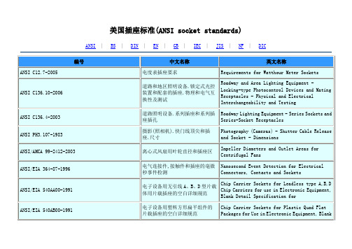
美国插标准
电连接器和插座的电容试验程序
Capacitance Test Procedure for Electrical Connectors and Sockets
ANSI/EIA-364-52A-2003
连接器/插座中使用的触点终端的软钎焊性的TP52试验程序
TP 52 Test Procedures for Solderability of Contact Terminations Use in Connectors/Sockets
ANSI/EIA-540A000-A-1990
ANSI/EIA 540AA00-1991
电子设备用无引线A、B、D型片载体用片载插座的空白详细规范
Chip Carrier Sockets for Leadless type A,B,D Chip Carriers for use in Electronic Equipment, Blank Detail Specification for
Combustion Characteristics Test Procedure for Electrical Connector Housing, Connector Assemblies and Sockets
ANSI/EIA-364-82A-2005
电连接器套、连接器组件和插座的塑料腐蚀性试验程序
Roadway and Area Lighting Equipment - Locking-type Photocontrol Devices and Mating Receptacles - Physical and Electrical Interchangeability and Testing
夏普光耦选型手册
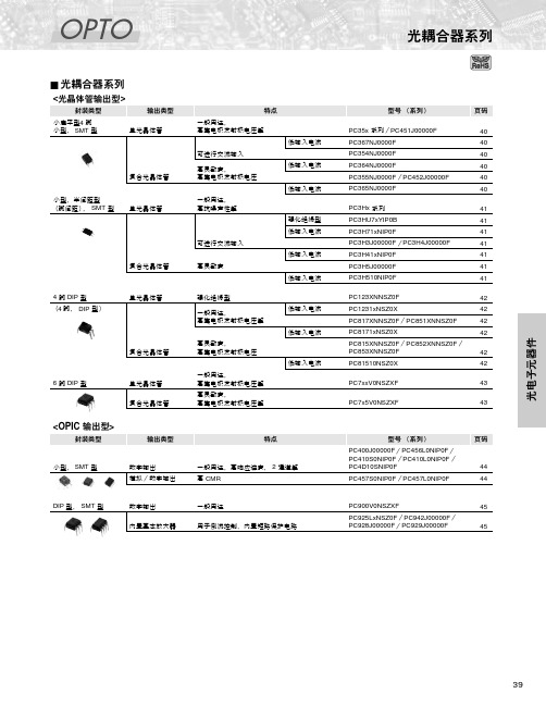
PC357NJ0000F
一般用途 一般用途, 高抗噪声性*1 高集电极发射极 电压 低输入电流, 高抗噪声性*1 可进行交流输入 低输入电流, 可进行交流输入, 高抗噪声性*1 高灵敏度
⅜❇
PC352NJ0000F 单 光 晶 体 管 输 出
⅜
50
3.75
80
90
5
5
4
2
100
2
PC451J00000F
PC714V0NSZXF PC724V0NSZXF
高绝缘电压 高绝缘电压, 大输入电流 高绝缘电压, 带基底端子 高绝缘电压, 高灵敏度 高绝缘电压, 高灵敏度, 高集电极发射极电压, 大功率
小型, SMT 型
数字输出 模拟/数字输出
一般用途,高响应速度, 2 通道等 高 CMR
44 44
DIP 型, SMT 型
数字输出 内置基本放大器
一般用途 用于倒流控制,内置短路保护电路
PC900V0NSZXF PC925LxNSZ0F /PC942J00000F/ PC928J00000F/PC929J00000F
安全标准*8
绝对最大额定值
光电特性
PC123XNNSZ0F*1, *5, *6, *7 单 PC1231xNSZ0X*1 光 晶 体 PC817XNNSZ0F*5, *6, *7 管 输 PC8171xNSZ0X*5, *6 出 PC851XNNSZ0F*5, *6
高绝缘电压,强化绝缘型 高绝缘电压,强化绝缘型, 低输入电流,高抗噪声性*4 高绝缘电压 高绝缘电压,低输入电流, 高抗噪声性*4 高绝缘电压, 高集电极发射极电压 高绝缘电压,高灵敏度 高绝缘电压, 高灵敏度,低输入电流 高绝缘电压, 高集电极发射极电压 高绝缘电压, 高集电极发射极电压
HCPL-7800
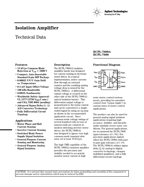
• Motor Phase and Rail Current Sensing
• Inverter Current Sensing • Switched Mode Power
Supply Signal Isolation • General Purpose Current
Sensing and Monitoring • General Purpose Analog
CAUTION: It is advised that normal static precautions be taken in handling and assembly of this component to prevent damage and/or degradation which may be induced by ESD.
Signal Isolation
Description
The HCPL-7800(A) isolation amplifier family was designed for current sensing in electronic motor drives. In a typical implementation, motor currents flow through an external resistor and the resulting analog voltage drop is sensed by the HCPL-7800(A). A differential output voltage is created on the other side of the HCPL-7800(A) optical isolation barrier. This differential output voltage is proportional to the motor current and can be converted to a singleended signal by using an op-amp as shown in the recommended application circuit. Since common-mode voltage swings of several hundred volts in teommon in modern switching inverter motor drives, the HCPL-7800(A) was designed to ignore very high common-mode transient slew rates (of at least 10 kV/µs).
LITHIUM METAL BATTERIES 安全物品指南说明书

January 2020 Printed or other static representations of this document are considered uncontrolled and Page 1 of 5for reference-only.FedEx Express does not provide these DG Labels. Customers may order these labels from vendors, such as those at /labels.Figure 1Figure 2Figure 3***Lithium Battery Class 9 Hazard Label Lithium Battery MarkCargo Aircraft Only Labe lNOTE : No text other than the Class “9” must be included in the bottom part of the Lithium Battery Class 9 label. IATA 7.2.2.4***Shipper must add UN number(s). It should be 12 mm high AND Shipper must complete phone number portion of label.AGGREGATE LITHIUM CONTENT - The sum of the grams of lithium content contained by the cells comprising a battery. [IATA Appendix A]In addition, check: /us/services/pdf/LithiumBatteries_Limitations.pdf2 1January 2020 Printed or other static representations of this document are considered uncontrolled and Page 2 of 5for reference-only.LITHIUM METAL BATTERIESLithium Metal Batteries packed with equipmentUN3091, P.I. 969Lithium Metal Batteries contained in equipmentUN3091, P.I. 970AGGREGATE LITHIUM CONTENT - The sum of the grams of lithium content contained by the cells comprising a battery. [IATA Appendix A]2LITHIUM ION BATTERIESJanuary 2020 Printed or other static representations of this document are considered uncontrolled and Page 3 of 5for reference-only.In addition, check: /us/services/pdf/LithiumBatteries_Limitations.pdf1LITHIUM ION BATTERIESJanuary 2020 Printed or other static representations of this document are considered uncontrolled and Page 4 of 5for reference-only.January 2020Printed or other static representations of this document are considered uncontrolled andPage 5 of 5for reference-only.Note:•FedEx Express will not accept any item with an A183 Special Provision, even with a Competent Authority approval. Any battery powered device subject to a recall will only be accepted if the recall is not safety related and the battery does not have the potential to cause a fire or dangerous evolution of heat. [FX-04E]•Lithium Batteries (Section I/IA/IB and Section II) must not be shipped in the same package with the following Hazard Classes/Divisions:1.4,2.1, 3, 4.1, 4.2, 4.3, 5.1, 5.2, 8, or 2.2 with a Cargo Aircraft Only label. This includes All Packed in One and Overpacks.Exception: If the only lithium batteries are those contained in temperature control devices and the lithium batteries are Section II. The package must also not require the Lithium Battery Mark and ELB (FedEx Express DG handling code for Section II batteries) must not be selected in the automation device. [FX-05C]•Shippers sending any data loggers which remain active in flight (other than FedEx SenseAware) must be pre-approved. Contact theFedExDangerousGoods/HazardousMaterialshotlineat(901)375-6806oremail:*************************************process. [FX-05D]•Hoverboards or similar self-balancing vehicles will only be accepted from companies if new, in unopened original packaging. Used,refurbished balancing vehicles shipments form individuals, resellers or third party shipments will not be accepted. [FX-04F]•Call FedEx customer service and ask for the International Hotline/ Specialist to check on commodity acceptability for international shipments1In addition, check: /us/services/pdf/LithiumBatteries_Limitations.pdf•Select ELB in your FedEx automation device, if selection is available for any Section II UN3091 or UN3481 required to be labeledwith the Lithium Battery Mark.Class 9 Miscellaneous DangerousGoods Hazard Label Lithium Battery LabelObsolete effective 01/01/19The Class 9 label cannot be used as the hazard label for Section I/IA/IB shipments effective 01/01/19.The Lithium Battery Class 9 hazard label must be used instead.If you have questions please contact the Dangerous Goods/Hazardous Materials Hotline at (800) GOFEDEX and press “81” or say dangerous goods. Press “4” to reach next available agent.DISCLAIMER:This guide is based upon the 2020 IATA Dangerous Goods Regulations and provides a general overview of lithium battery shipping requirements. It does not provide complete shipping information. Consult the packing instruction and all applicable Special Provisions for the product being shipped.These materials are provided as a courtesy, to be used as guidelines to assist properly trained shippers. These materials do not alter, satisfy, or influence anygovernmental requirements. The contents of these materials are subject to change due to constant changes in government regulations. FedEx Express accepts noliability for loss or damage resulting from changes, errors, omissions, or misinterpretations of these materials.Lithium Battery MarkThis mark can be printed in color, completed as shown in the example on the right, and affixed to the package.When printing, be sure to select "No" for "Expand/reduce page."Please understand that FedEx Express accepts no liability for loss or damage caused by using this data.【Minimum size 】The mark must be in the form of a rectangle with hatched edging.The mark must be a minimum dimension of 120 mm wide × 110 mm high and the minimum width of the hatching must be 5 mm. If the size of the package so requires, the dimensions/line thickness may be reduced to not less than 105 mm wide × 74 mm high. 【Color 】The hatching must be red.The symbol must be black on white or suitable contrasting background.【Markings on the lithium battery mark 】 The mark must indicates as below:● The appropriate UN number preceded by the letters “UN” and it should be at least 12mm high- “UN3090” for lithium metal cells or batteries; - “UN3480” for lithium ion cells or batteries;- “UN3091” for lithium metal cells or batteries contained in, or packed with, equipment; or - “UN3481” for lithium ion cells or batteries contained in, or packed with, equipment. - Where a package contains lithium cells or batteries assigned to different UN numbers, all applicable UN numbers must be indicated on one or more marks.● A telephone number for additional informationThe telephone number required on the lithium battery mark can be a 24-hour monitored number, or other normal office hour number provided a person knowledgeable of the lithium batteries being shipped is readily available. The telephone number must start with the country code. 【On your Air Waybill 】Where a consignment includes packages bearing the lithium battery mark for Section II, the words must be included on the air waybill as below: - “Lithium metal batteries in compliance with Section II of PI969” for UN3091 lithium metal cells or batteries packed with equipment; - “Lithium metal batteries in compliance with Section II of PI970” for UN3091 lithium metal cells or batteries contained in equipment; - “Lithium ion batteries in compliance with Section II of PI966” for UN3481 lithium ion cells or batteries packed with equipment; - “Lithium ion batteries in compliance with Section II of PI967” for UN3481 lithium ion cells or batteries contained in equipment.UN3481 +81-3-9876-5432 Figure 2ExamplePrinted or other static representations of this document are considered uncontrolled and for reference-only.01/2020Due to an IATA regulation to prohibit transport of lithium metal batteries on passenger aircraft effective as of January 1, 2015, there will be certain restrictions in destinations where FedEx is able to accept lithium metal battery shipmentsFedEx will limit transport of UN3090 shipments to locations where Dangerous Goods are accepted via FedEx International Priority Service. However, depending on required routing, these shipments may need to be returned to shippers due to prohibitions on carrying such shipments aboard passenger aircraft.This restriction only applies to lithium metal batteries when shipped by themselves, and does not apply to batteries packed with equipment or contained in equipment.How to obtain preapprovalShippers must be preapproved by FedEx Express Dangerous Goods Administration in order to ship lithium metal batteries, UN 3090 Section IA and Section IB.Note:Effective Jan. 1, 2017, FedEx Express will no longer accept UN 3090 or UN 3480 lithium batteries tendered to us as IATA Section II. Instead, these shipments must be tendered as fully regulated Section I (either Section IA or Section IB).Shippers who are on the UN 3090 Section II preapproved list will automatically be placed on the UN 3090 Section I list. You will not need to reapply for preapproval. The Section II Exception Label can no longer be used effective Jan. 1, 2017.Obtain PreapprovalShippers must submit the following information to be considered by FedEx Express Dangerous Goods Administration for approval to ship lithium metal batteries.1. FedEx account number2. Company name and complete address (include country for orders outside the U.S.)3. Contact name(s) and phone number (in case of questions related to the preapproval)4. Type of preapproval requested (fully regulated UN 3090, lithium metal batteries)5. A detailed description and digital photos or diagrams of your inner packaging. Packaging must be designed to protect thebattery terminals from contact with another lithium battery or cell (or metal or any item that is capable of conducting electricity) in order to prevent short-circuiting.6. Proof of UN38.3 testSubmit the above information to **********************************. Information must be submitted in English. Please allow two business days for a response from FedEx. If you are unable to send your request via email, please contact the Customer Service Hotline at 0120-003200to discuss other means to submit your request for approval.DISCLAIMER:This guide is based upon the 2020 “IATA Dangerous Goods Regulations” and provides a general overview of lithium battery shipping requirements. It does not provide complete shipping information. Consult the packing instruction and all applicable Special Provisions for the product being shipped.These materials are provided as a courtesy, to be used as guidelines to assist properly trained shippers. These materials do not alter, satisfy, or influence any governmental requirements. The contents of these materials are subject to change due to constant changes in government regulations. FedEx Express accepts no liability for loss or damage resulting from changes, errors, omissions, or misinterpretations of these materials.01/2020。
TE产品规范(114-)双操作手工紧紧器工具说明书
47995Portable Crimp Tools, Premium Crimp Tooling, Not Releasable, Not Adjustable,Fixed In Tool, TE Product Specification (114-), Battery / ManualApplication Tooling>Portable Crimp ToolsCertification:Yes – Certificate IncludedSpecification Type:TE Product Specification (114-)Die Sets Type:Fixed In ToolRatchet Configuration:Not Releasable, Not AdjustableTool Grade:Premium Crimp ToolingFeaturesOtherCrimp Form-Wire Barrel Type Open Barrel - F CrimpTool Grade Premium Crimp ToolingRatchet Configuration Not Releasable, Not AdjustableDie Sets Type Fixed In ToolSpecification Type TE Product Specification (114-)Certification Yes – Certificate IncludedPower Type Battery, ManualTool Type Double Action Hand ToolProduct ComplianceFor compliance documentation, visit the product page on >EU RoHS Directive 2011/65/EU Out of ScopeEU ELV Directive 2000/53/EC Out of ScopeChina RoHS 2 Directive MIIT Order No 32, 2016Not reviewed for China RoHS complianceEU REACH Regulation (EC) No. 1907/2006Current ECHA Candidate List: JUN 2020(209)Candidate List Declared Against: JUN 2016(169)Does not contain REACH SVHC 47995 ACTIVEAMPTE Internal #:47995Portable Crimp Tools, Premium Crimp Tooling, Not Releasable,Not Adjustable, Fixed In Tool, TE Product Specification (114-),Battery / ManualView on >Halogen Content Not Yet Reviewed for halogen content Solder Process CapabilityNot applicable for solder process capabilityProduct Compliance DisclaimerThis information is provided based on reasonable inquiry of our suppliers and represents our current actual knowledge based on the information they provided. This information is subject to change. The part numbers that TE has identified as EU RoHS compliant have a maximum concentration of 0.1% by weight in homogenous materials for lead, hexavalent chromium, mercury, PBB, PBDE, DBP, BBP, DEHP, DIBP, and 0.01% for cadmium, or qualify for an exemption to these limits as defined in the Annexes of Directive 2011/65/EU (RoHS2). Finished electrical and electronic equipment products will be CE marked as required by Directive 2011/65/EU. Components may not be CE marked.Additionally, the part numbers that TE has identified as EU ELV compliant have a maximum concentration of 0.1% by weight in homogenous materials for lead, hexavalent chromium, and mercury, and 0.01% for cadmium, or qualify for an exemption to these limits as defined in the Annexes of Directive 2000/53/EC (ELV). Regarding the REACH Regulations, TE’s information on SVHC in articles for this part number is still based on the European Chemical Agency (ECHA) ‘Guidance on requirements for substances in articles’(Version: 2, April 2011), applying the 0.1% weight on weight concentration threshold at the finished product level. TE is aware of the European Court of Justice ruling of September 10th, 2015 also known as O5A (Once An Article Always An Article) stating that, in case of ‘complex object’, the threshold for a SVHC must be applied to both the product as a whole and simultaneously to each of the articles forming part of its composition. TE has evaluated this ruling based on the new ECHA “Guidance on requirements for substances in articles” (June 2017, version 4.0) and will be updating its statements accordingly.TE Model / Part #342413-4RECEPTACLE STRIPTE Model / Part #342873-3POS MATE STECKH 6,3TE Model / Part #342873-1POS MATE STECKH 6,3TE Model / Part #342413-3POS MATE STECKHUELSTE Model / Part #342413-1POS MATE STECKHUELSTE Model / Part #1-342413-2POSI-MATE RECPT STRIPTE Model / Part #42475-2FASTON 250 TERMINAL TAB 22-18 AWG TPBRTE Model / Part #342413-2POSI-MATE RECPT.TE Model / Part #42475-3FASTON 250 TERMINAL TAB 22-18 AWG BRTE Model / Part #42475-4FASTON 250 TERMINAL TAB 22-18 AWG TPBRCompatible PartsCustomers Also BoughtTE Model / Part #7798056036LSTT-9.5-0-40MMTE Model / Part #5628376016LSTT-32-0-60MMTE Model / Part #372259-000B-070-12-10TE Model / Part #D867683001ACW0219-0.35-92(NS)TE Model / Part #9-1579018-3EXTRACTION TOOLTE Model / Part #456418-2CRIMP.,WIRE(070FX150THK)TE Model / Part #3-1579018-0EXTRACTION TOOLTE Model / Part #1801177-53W TAB CONNECTOR HP GREENTE Model / Part #3-1393788-5AXICOM P2 STANDARDTE Model / Part #CH18196001Single Wall RNF-100 Stick HS TubingCustomers Also BoughtDocumentsDatasheets & Catalog PagesCrimp Term Whitepaper-Use the Right Tool 1-1773953-1EnglishCRIMPING WHERE FORM MEETS FUNCTIONEnglishBottoming DiesEnglishInstruction SheetsHand Crimping Tool 47995EnglishInstruction Sheet (U.S.)English。
1435-2;1431-1;1431-2;1420-1;1420-2;中文规格书,Datasheet资料
M I C R O J A C K S98density packaging•Beryllium Copper multi-spring contact maintains retention after multiple insertions•Ideal for mounting transistors,re-sistors,diodes,IC’s and similar miniature components•Custom micro jacks manufactured to your specifications •Other platings available upon request.016 [0.41].083[2.11].055[1.40]L3-FINGER CLOSED ENTRY CONTACT.038[0.96].038[0.96]HEX ..020[0.50].130 [3.3].095 [2.4]L.072[1.9].045[1.14]4-FINGER CLOSED ENTRY CONTACT.056[1.42].049[1.24].041[1.04].063[1.60]4-FINGER CLOSED ENTRY CONTACT.205[5.2].089[2.23].248[6.3]4-FINGER CLOSED ENTRY CONTACT.120[3.1].259[6.6].233[5.9].060[1.52]DIA..014[0.4].077[2.0]DIA..015(.38)-.021(.53)PIN -SOLDER MOUNT.015(.38)-.021(.53)PIN -PRESS FIT.015(.38)-.025(.64)PIN -TAPER-FIT.022(.56)-.032(.81)PIN -SOLDER MOUNT.015(.38)-.025(.64)PIN -SOLDER MOUNT.015(.38)-.025(.64)PIN -SOLDER MOUNT.022(.56)-.034(.86)PIN -PRESS FIT.025(.64)-.037(.94)PIN -PRESS FIT.025(.64)-.037(.94)PIN -SOLDER MOUNT.055[1.39].072[1.83].016 [0.41]4-FINGER CLOSED ENTRY CONTACT.093 [2.36].142[3.6].161[4.1]RoHS NON-RoHS Mtg.GOLD/GOLD TIN/TIN TIN/GOLD L Hole CAT.NO.CAT.NO.CAT.NO.Length Dia.1411-11431-11420-1.140(3.6).0421411-21431-21420-2.170(4.3)(1.07)RoHS NON-RoHS Mtg.GOLD/GOLD TIN/TIN TIN/GOLD L Hole CAT.NO.CAT.NO.CAT.NO.Length Dia.1412-11432-11468-1.140(3.6).0401412-21432-21468-2.170(4.3)(1.02)1412-31432-31468-3.282(7.2)RoHS NON-RoHS Mtg.GOLD/GOLD TIN/TIN TIN/GOLD L Hole CAT.NO.CAT.NO.CAT.NO.Length Dia.1415-11435-11469-1.160(4.1).0551415-21435-21469-2.190(4.8)(1.40)RoHS NON-RoHS Mtg.GOLD/GOLD TIN/TIN TIN/GOLD Hole CAT.NO.CAT.NO.CAT.NO.Dia.169316941695.063(1.60)RoHS NON-RoHS Mtg.GOLD/GOLD TIN/TIN TIN/GOLD Hole CAT.NO.CAT.NO.CAT.NO.Dia.141314331470.059(1.50)RoHS NON-RoHS Mtg.GOLD/GOLD TIN/TIN TIN/GOLD Hole CAT.NO.CAT.NO.CAT.NO.Dia.160316061607.052(1.32).061 [1.55].015[0.38].028[0.71].091 [2.3].086[2.2].170[4.3].200[5.1].070 [1.78]KNURL6-FINGER CLOSEDENTRY CONTACT6-FINGER CLOSED ENTRY CONTACT.057[1.45].077[1.96].083[2.11].025[0.7]L.025(.64)-.037(.94)PIN -SOLDER MOUNTRoHS NON-RoHS Mtg.GOLD/GOLD TIN/TIN TIN/GOLD Hole CAT.NO.CAT.NO.CAT.NO.Dia.141614361471.067(1.70)RoHSNON-RoHS Mtg.GOLD/GOLD TIN/TIN TIN/GOLD L Hole CAT.NO.CAT.NO.CAT.NO.Length Dia.1626-11614-11619-1.095(2.4).0621626-21614-21619-2.105(2.7)(1.57)1626-31614-31619-3.155(3.9).045 [1.14].062[1.57].090[2.29]6-FINGER CLOSED ENTRY CONTACT.080 [2.03].083 [2.11].022(.56)-.034(.86)PIN -SOLDER MOUNTRoHS NON-RoHS Mtg.GOLD/GOLD TIN/TIN TIN/GOLD Hole CAT.NO.CAT.NO.CAT.NO.Dia.165816591673.065(1.65).128[3.3].168[4.3].040 [1.02].092 [2.34].065 [1.65]L.200[5.1].230[5.9]4-FINGER CLOSED ENTRY CONTACT.125 [3.2].032(.81)-.046(1.17)PIN -SWAGE MOUNTRoHS NON-RoHS Mtg.GOLD/GOLD TIN/TIN TIN/GOLD Hole CAT.NO.CAT.NO.CAT.NO.Dia.359035913592.065(1.65)RoHS NON-RoHS Mtg.GOLD/GOLD TIN/TIN TIN/GOLD Hole CAT.NO.CAT.NO.CAT.NO.Dia.169716981699.063(1.60)RoHSNON-RoHS Mtg.GOLD/GOLD TIN/TIN TIN/GOLD L Hole CAT.NO.CAT.NO.CAT.NO.Length Dia.1419-11439-11478-1.062(1.6).0691419-21439-21478-2.094(2.4)(1.75)PLATING OPTIONSCONTACT PLATING BODY SPRING RoHS Gold/Gold Gold Gold Compliant Tin/Tin Tin/Lead Tin/Lead Non-CompliantTin/GoldTin/LeadGoldBody:Brass,ASTM-B16Spring:Beryllium Copper(QQ-C-533).057[1.45]HEX.057[1.45]DIA..200[5.1].020[0.52].078[1.98]DIA.6-FINGER CLOSED ENTRY CONTACT.165[4.2].078[1.98].040[1.02].090[2.29].040[1.02].062[1.57].210[5.3].187[4.7].180[4.6]6-FINGER CLOSED ENTRY CONTACTRoHS Plating:Gold:.000010per MIL-G-45204(RoHS Compliant)Tin/Lead:.000200to.000300per MIL-T-10727,Type 1(Non-RoHS Compliant).038[0.96]3-FINGER CLOSED ENTRY CONTACTL .055[1.40].083[2.11].016[0.41]RoHS Tel (718)956-8900•Fax (718)956-9040(800)221-5510•kec@31-0720th Road –Astoria,NY 11105-2017RoHS COMPLIANT ~ISO 9001CERTIFIED®分销商库存信息:KEYSTONE-ELECTRONICS1435-21431-11431-2 1420-11420-21470 1411-11411-21435-1 1469-11469-21614-3 1468-11468-21607 16951619-31606 169414711699 1415-11415-21413 359116981659 359216031432-1 1432-21432-31673 1468-316581697 1614-214161619-1 1619-216933590 1626-11626-21626-3 1412-11412-21412-3 1439-11439-21478-2 1419-21419-1。
安捷伦 A5000系列(S5008) 光学鼠标芯片资料Datasheet
ADNS-5000 Optical Mouse Sensor Data SheetDescriptionThe ADNS-5000 is a one-chip USB optical mouse sensor for implementing a non-mechanical tracking engine for computer mice.It is based on optical navigation technology that measures changes in position by optically acquiring sequential surface images (frames) and mathemati-cally determining the direction and magnitude of move-ment.The sensor is in a 18-pin optical package that is designed to be used with the ADNS-5100 Round Lens or ADNS-5100-001 Trim Lens, the ADNS-5200 Clip, and the HLMP-ED80-XX000 LED. These parts provide a complete and compact mouse sensor. There are no moving parts, and precision optical alignment is not required, facilitating high volume assembly.The output format is USB. This device meets USB revision1.1 specifications and is compatible with USB Revision2.0 specification.Default resolution is specified as 500 counts per inch, with rates of motion up to 16 inches per second and 2g acceleration. Resolution can also be programmed to 1000 cpi. Frame rate is varied internally by the sensor to achieve tracking and speed performance, eliminating the need for the use of many registers.A complete mouse can be built with the addition of a PC board, switches, mechanical Z-wheel, plastic case and cable. A 1% pull up resistor is needed for the USB port to signify a low speed HID device.Featuresx Optical navigation technologyx No mechanical moving partsx High reliabilityx Complete 2-D motion sensorx High speed motion detectionx Accurate navigation over a wide variety of surfaces x No precision optical alignment neededx Wave Solderablex IEC 60825-1 eye safe under single fault conditionsx Single 5.0 volt power supplyx Meets USB Revision 1.1 Specification and compatible with USB Revision 2.0 specificationx Meets HID Revision 1.1x On Chip LED Drive with regulated current Applicationsx Mice for desktop PC’s, Workstations, and portable PC’sx TrackballsxIntegrated input devicesFigure 1. Package outline drawing (top view)Theory of OperationThe ADNS-5000 is based on Optical Navigation Technol-ogy. It contains an Image Acquisition System (IAS), a Digital Signal Processor (DSP) and USB stream output.The IAS acquires microscopic surface images via the lens and illumination system provided by the ADNS-5100 Round Lens or ADNS-5100-001 Trim Lens, ADNS-5200, and HLMP-ED80-XX000. These images are processed by the DSP to determine the direction and distance of mo-tion. The DSP generates the 'x and 'y relative displace-ment values which are converted to USB motion data.PinoutPin PinDescription1 D +USB D+ line2 D -USB D- line3ZA Scroll wheel quadrature input 4ZB Scroll wheel quadrature input 5LGND LED ground 6XYLED XYLED Input7VDD5 5 Volt Power (USB VBUS)8GND System ground 9REG0 3 Volt Power 10VDD3 3 Volt Power11OPT 0Descriptor Select 1 or B412OPT 1Descriptor Select 2 or B513GND System ground 14OSC_IN Ceramic resonator input 15OSC_OUT Ceramic resonator output 16B3Button 3 input (switch to ground)17B2Button 2 input (switch to ground)18B1Button 1 input (switch to ground)11 OPT 0 (B4)12 OPT 1 (B5)15 OSC_OUT14 OSC_IN13 GND18 B117 B216 B310 VDD3GND 8VDD5 7ZB 4LGND 5XYLED 6D+ 1D- 2ZA 3REG0 9Figure 2. Package outline drawingCAUTION: It is advised that normal static precautions be taken in handling and assemblyof this component to prevent damage and/or degradation which may be induced by ESD.scribing the base plate molding features for lens and PCB alignment.Figure 4. 2D assembly drawing of ADNS-5000Figure 3. Recommended PCB mechanical cutouts and spacing (Top view)The components interlock as they are mounted onto defined features on the base plate.The ADNS-5000 sensor is designed for mounting on a through hole PCB, looking down. The aperture stop and features on the package align it to the lens (See figure 3).The ADNS-5100 Round lens provides optics for the imag-ing of the surface as well as illumination of the surface at the optimum angle. Lens features align it to the sensor, base plate, and clip with the LED. The lens also has a largeFigure 5. Exploded view drawinground flange to provide a long creepage path for any ESD events that occur at the opening of the base plate (See figure 4).The ADNS-5200 clip holds the LED in relation to the lens. The LED must be inserted into the clip and the LED’s leads formed prior to loading on the PCB.The HLMP-ED80-XX000 LED is recommended for illumi-nation. If used with the bin table, sufficient illumination can be guaranteed.Block DiagramFigure 6. Block DiagramZBZAZ WHEELOSCILLATORLED OSC_OUTVOLTAGE REFERENCE D -USB PORT5 VOLT POWERBUTTONSB4B3B2B1B5PCB Assembly Considerations1. Insert the sensor and all other electrical components into PCB.2. Bend the LED leads 90 degrees and then insert the Led into the assembly clip until the snap feature locks the Led base.3. Insert the LED/clip assembly into PCB.4. Wave solder the entire assembly in a no-wash solder process utilizing solder fixture. The solder fixture is needed to protect the sensor during the solder process. The fixture should be designed to expose the sensor leads to solder while shielding the optical aperture from direct solder contact.5. Place the lens onto the base plate.6. Remove the protective Kapton tape from optical aperture of the sensor. Care must be taken to keep contaminants from entering the aperture. Recom-mend not placing the PCB facing up during the entire mouse assembly process. Recommend to hold the PCB first vertically for the Kapton removal process.7. Insert PCB assembly over the lens onto base plate aligning post to retain PCB assembly. The sensor ap-erture ring should self-align to the lens.8. The optical position reference for the PCB is set by the base plate and lens. Note that the PCB motion due to button presses must be minimized to maintain optical alignment.9. Install mouse top case.Figure 7. Typical ApplicationDesign considerations for improving ESD PerformanceThe table below shows typical values assuming base plate construction per the Avago Technologies supplied IGES file and ADNS-5100 Round lens.Typical distanceA5100A5100-001Creepage 40.5mm 17.9mm Clearance32.6mm9.2mmTypical ApplicationRegulatory Requirementsx Passes F CC B and worldwide analogous emission limits when assembled into a mouse with unshielded cable and following Avago Technologies recommen-dations.x Passes EN61000-4-4/IEC801-4 EFT tests when assem-bled into a mouse with shielded cable and following Avago Technologies recommendations.x UL flammability level UL94 V-0.x Provides sufficient ESD creepage/clearance distance to avoid discharge up to 15kV when assembled into a mouse according to usage instructions above.Notes on bypass capacitors:x All caps (except C4) MUST be as close to the sensor pins as possible.x Caps should be ceramic.x Caps should have less than 5 nH of self inductance x Caps connected to VDD3 MUST have less than 0.2: ESRx 1.5k : resistor should be ± 1% tolerance.x Z-wheel connections are detailed in Figure 20x Buttons B1-B5 can be used as button or VID/PID straps (see strap table on page 14). For VID/PID connections, parts must be connected to Vdd3 on ‘high’ connec-tion, preferably near pin 10Surface mount parts are recommendedFigure 8. Application Schematic for 3 buttons and 5 buttonsAbsolute Maximum RatingsRecommended Operating ConditionsFigure 9. Distance from lens reference plane to object surfaceParameterSymbolMinimumMaximumUnitsNotesStorage Temperature T S -4085 q C Operating Temperature T A-1555 q C Lead Solder Temp 260 q C For 10 seconds, 1.6mm below seating plane.Supply Voltage V DD-0.55.5 V ESD 2 kV All pins, human body model MIL 883 Method 3015Input Voltage V IN -0.5V DD +0.5 V All I/O pins except OSC_IN and OSC_OUT, D+, D- Input Voltage V IN -1.0 4.6 V D+, D-, AC waveform, see USB specification (7.1.1)Input VoltageV IN -0.5 3.6 V OSC_IN and OSC_OUTInput Short Circuit VoltageV SCV DDVD+, D-, see USB specification (7.1.1)ParameterSymbolMinimumTypicalMaximumUnitsNotesOperating Temperature T A 040 q C Power supply voltage V DD 4.0 5.0 5.25Volts For accurate navigation and proper USB operationPower supply voltage V dd 3.8 5.05.25Volts Maintains communication to USB host and internal register contents.Power supply rise time V RT 0.1100ms Supply noise V N 100mV Peak to peak within 0-100 MHz bandwidthVelocity Vel 16ips Acceleration Acc 2 GClock Frequency f clk 23.642424.36MHz Due to USB timing constraints Resonator Impedance X RES 55 :Distance from lens refer-ence plane to surface Z 2.3 2.42.5mm See Figure 9 Light Level onto ICIRR INC8010025,00030,000mW/m 2=639nm =875nmElectrical Characteristics over recommended operating conditions. Typical values at 25 °C, V DD =5.0 V, 24MHz USB Electrical SpecificationsElectrical Characteristics over recommended operating conditions. ParameterSymbolMin.Typ.Max.UnitsNotesPower up delay T PUP 50ms Debounce delay on button inputs T DBB5917ms“Maximum” specified at 8ms polling rate. Mechanical Z-Wheel Internally pulled down with 20k resistors and debouncedTransient Supply CurrentI DDT60mAMax. supply current during a VDD ramp from 0 to 5.0 V with > 500 s rise time. Does not include charging currents for bypass capacitors.Input Capacitance(OSC Pins)C OSC_IN50pFOCS_IN, OSC_OUT to GNDParameterSymbolMin.Max.UnitsNotesOutput Signal Crossover Voltage V CRS 1.3 2.0V C L = 200 to 600 pF (see Figure 10)Input Signal Crossover Voltage V ICRS 1.2 2.1V C L = 200 to 600 pF (see Figure 10)Output High V OH 2.8 3.6V with 15 kohm to Ground and 7.5 k to Vbus on D- (see Figure 11)Output Low V OL 0.00.3V with 15 kohm to Ground and 7.5 k to Vbus on D- (see Figure 11)Single Ended Output V SE00.8V Input High (Driven)VI H 2.0V Input High (Floating)V IHZ 2.7 3.6V Input LowV IL 0.8V 7.5k to Vdd5Differential Input Sensitivity V DI 0.2V |(D+)-(D-)| See Figure 12Differential Input Common Mode RangeV CM 0.8 2.5V Includes V DI , See Figure 12Single Ended Receiver Threshold V SE 0.82.0V Transceiver Input CapacitanceC IN12pFD+ to V BUS , D- to V BUSTiming Specifications over recommended operating conditions.Parameter Symbol Min.Max.Units NotesD+/D- Transition rise time T LR75ns C L = 200 pF (10% to 90%), see Figure 10D+/D- Transition rise time T LR300ns C L = 600 pF (10% to 90%), see Figure 10D+/D- Transition fall time T LF75ns C L = 200 pF (90% to 10%), see Figure 10D+/D- Transition fall time T LF300ns C L = 600 pF (90% to 10%), see Figure 10Rise and Fall time matching T LRFM80125%T R/T F; C L = 200 pF; Excluding the first transitionfrom the Idle StateWakeup delay from USB suspend mode due to buttons push T WUPB17ms Delay from button push to USB operationOnly required if remote wakeup enabledWakeup delay from USB suspend mode due to buttons push until accurate navigation T WUPN50ms Delay from button push to navigation operationOnly required if remote wakeup enabledUSB reset time T reset18.7sData Rate t LDRATE 1.4775 1.5225Mb/s Average bit rate, 1.5 Mb/s +/- 1.5% Receiver Jitter Tolerance t DJR1-7575ns To next transition, see Figure 13 Receiver Jitter Tolerance t DJR2-4545ns For paired transitions, see Figure 13 Differential to EOP TransitionSkewt LDEOP-40100ns See Figure 14EOP Width at Receiver t LEOPR670ns Accepts EOP, see Figure 14Source EOP Width t LEOPT 1.25 1.50sWidth of SE0 interval duringDifferential Transitiont LST210ns See Figure 11.Differential Output Jitter t UDJ1-9595ns To next transition, see Figure 15Differential Output Jitter t UDJ2-150150ns For paired transitions, see Figure 15Figure 10. Data Signal Rise and Fall TimesFigure 11. Data Signal Voltage LevelsFigure 12. Differential Receiver Input Sensitivity vs. Common Mode Input RangeV CRSRise TimeFall TimeV OLV OH V OH (min)V OL (max)GNDV IH (min)V IL (max)t LSTInput Voltage Range (volts)Figure 13. Receiver Jitter ToleranceFigure 14. Differential to EOP Transition Skew and EOP WidthFigure 15. Differential Output JitterT PERIODPERIOD DJR2Data T PERIODDifferential Data LinesT PERIODDifferential Data LinesDC Electrical SpecificationsElectrical Characteristics over recommended operating conditions. Typical values at 25 °C, V DD =5.0 V, 24MHz ParameterSymbolMinimum TypicalMaximum UnitsNotesSupply current (Sensor only), mouse moving I DDS 7.2mA No load on B1-B3, Z-LED, XYLED ZA, ZB, D+, D-Supply current (Sensor only), mouse not moving I DDSN 6.2mANo load on B1-B3, Z-LED, XYLED ZA, ZB, D+, D-Supply current, USB suspend mode I DDSS 250 P A No load on B1-B3, Z-LED, XYLED ZA, ZB, D+, D-XYLED current I LED 30mA XYLED Output Low Voltage V OL 1.1V Refer to Figure 16Input Low VoltageV IL0.5VPins: ZA, ZB, B1, B2, B3, V IL max of 0.5V DC is at V DD min of 4V DC , with a typical of 0.8V DC at V DD of 5V DC Input High Voltage V IH 0.6*V DDV Pins: ZA, ZB, B1, B2, B3 Input Hysteresis V HYST 285mV Pins: ZA, B1, B2, Input Hysteresis V HYST 200mV Pins: ZB Button Pull Up CurrentB IOUT125275500APins: B1, B2, B3Typical Performance CharacteristicsPerformance Characteristics over recommended operating conditions. Typical values at 25 °C, V DD =5.0 V, 24MHz Parameter Symbol Minimum TypicalMaximum UnitsNotesPath Error (Deviation)P Error0.5%Average path error as percent of total2.5” travel on various standard surfacesTypical Performance CharacteristicsPerformance Characteristics over recommended op-erating conditions. Typical values at 25 °C, V DD =5.0 V, 24MHzFigure 16. Typical Resolution vs. Z [2,3]Figure 17. Wavelength responsivity.[1] (Comparative Surfaces)The following graphs are the typical performance of the ADNS-5000 sensor, assembled as shown in the 2D assem-bly drawing with the ADNS-5100 Round Lens/Prism, the ADNS-5200 clip, and the HLMP-ED80-XX000 LED.00.10.20.30.40.50.60.70.80.914005006007008009001000Wavelength in nmN o r m a l i s e d r e s p o n s eNotes:1. The ADNS-5000 is designed for optimal performance when used with the HLMP-ED80-XX000 (Red LED 639nm).2. Z = distance from Lens Reference Plane to Surface.3. DOF = Depth of Field11-0.8-0.6-0.4-0.20.20.40.60.81Z-H eight(mm)R e s o l u t i o n (D P I )Configuration after Power up (Data Values)Signal Function State from Figure 9-1 of USB spec:Powered or Default Address or ConfiguredState from Figure 9-1 of USB spec:Suspended from any other stateB1Hi-Z if tied to VDD3 else pullup active Hi-Z if tied to VDD3 else pullup activeB2Hi-Z if tied to VDD3 else pullup active Hi-Z if tied to VDD3 else pullup activeB3Hi-Z if tied to VDD3 else pullup active Hi-Z if tied to VDD3 else pullup activeB4Hi-Z if tied to VDD3 else pullup active Hi-Z if tied to VDD3 else pullup activeB5Hi-Z if tied to VDD3 else pullup active Hi-Z if tied to VDD3 else pullup activeD-USB I/O Hi-Z inputD+USB I/O Hi-Z inputOSC_IN24MHz pulled lowOSC_OUT24MHzXYLED low (on) or pulsing Pulled high (off)ZB/Z_LED Hi-Z input Hi-Z inputZA Hi-Z if ZA tied to GND Hi-Z inputStrap (Jumper) TableThe PID/string strap matrix is the following:Mouse type VID PID Manuf str. Product string B1B2 B3 OPT 0OPT 1ZA ZB3-button mse 0x192F0x0116“““USB OpticalMouse”sw1 sw2 sw3Vdd3 Vdd3mechZ-wheelmechZ-wheel5-button mse 0x192F 0x0216“““USB OpticalMouse”sw1 sw2 sw3sw4 sw5mechZ-wheelmechZ-wheelXY LEDx The peak current values are 30 mA if R1 59ohm and the part meets the IEC 825-1 eye safety regulations.ButtonsThe minimum time between button presses is T DBB . But-tons B1 through B3 are connected to a Schmidt trigger input with 100 uA current sources pulling up to +5 volts during normal, sleep and USB suspend modes.Notes:For mechanical Z-wheels the following must be imple-mented:x Use a rotary switch equivalent to the Panasonic part EVQVX at /www-data/pdf/ATC0000/ATC0000CE20.pdf (The key point is stable “A” switch state in all detent positions).x Solder the rotary switch into the PCB such that the common pin is closest to the cable end of the mouse. (Metal plate faces to left)x Connect the “A” terminal of the rotary switch to “ZA” and the “B” terminal to “ZB”. ZA MUST be connected to “Signal A” in Figure 19 where the z-wheel detents are mechanically stable.Figure 19. Z-Wheel A and B connectionsZ-WheelThe mechanical Z-Wheel connections (A,B) are deter-mined below.X & Y Directions(Looking through an ADNS-5100 Lens)The positive and negative X and Y directions with respect to the mouse case are shown in the diagram below.Top Xray View of MousePOSITIVE XP O S T E YI I V Figure 18. Directions are for a complete mouse, with the ADNS-5100 lensUSB CommandsMnemonic Command NotesUSB_RESET D+/D- low > 18.6 us Device Resets; Address=0USB_SUSPEND Idle state > 3mS Device enters USB low-power modeUSB_RESUME Non-idle state Device exits USB low-power modeGet_Status_Device80 00 00 00 00 00 02 00Normally returns 00 00, Self powered 00 00,Remote wakeup 02 00Get_Status_Interface81 00 00 00 00 00 02 00Normally returns 00 00Get_Status_Endpt082 00 00 00 xx 00 02 00OUT: xx=00, IN: xx=80Normally returns 00 00Get_Status_Endpt182 00 00 00 81 00 02 00Normally returns 00 00, Halt 00 01Get_Configuration80 08 00 00 00 00 01 00Return: 00=not config., 01=configuredGet_Interface81 0A 00 00 00 00 01 00Normally returns 00Get_Protocol A1 03 00 00 00 00 01 00Normally returns 01, Boot protocol 00Get_Desc_Device80 06 00 01 00 00 nn 00See USB command detailsGet_Desc_Config80 06 00 02 00 00 nn 00See USB command detailsGet_Desc_String80 06 xx 03 00 00 nn 00See USB command detailsGet_Desc_HID81 06 00 21 00 00 09 00See USB command detailsGet_Desc_HID_Report81 06 00 22 00 00 nn 00See USB command detailsGet_HID_Input A1 01 00 01 00 00 nn 00Return depends on motion & configGet_Idle A1 02 00 00 00 00 01 00Returns rate in multiples of 4msGet_Vendor_Test C0 01 00 00 xx 00 01 00Read register xxSet_Address00 05 xx 00 00 00 00 00xx = addressSet_Configuration00 09 xx 00 00 00 00 00Not configured: xx=00Configured: xx=01Set_Interface01 0B 00 00 00 00 00 00Only one interface supportedSet_Protocol21 0B xx 00 00 00 00 00Boot: xx=00, Report: xx=01Set_Feature_Device00 03 01 00 00 00 00 00Enable remote wakeupSet_Feature_Endpt002 03 00 00 xx 00 00 00Halt. OUT: xx=00, IN: xx=80Set_Feature_Endpt102 03 00 00 81 00 00 00HaltClear_Feature_Device00 01 01 00 00 00 00 00Disable Remote wakeupClear_Feature_Endpt002 01 00 00 xx 00 00 00Clear Halt; OUT: xx=00, IN: xx=80Clear_Feature_Endpt102 01 00 00 81 00 00 00Clear HaltSet_Idle21 0A 00 rr 00 00 00 00rr = report rate in multiples of 4msSet_Vendor_Test40 01 00 00 xx yy 00 00Write yy to address xxPoll_Endpt1Read buttons, motion, & Z-wheelNote:The last two bytes in a command shown as “nn 00” specify the 16-bit data size in the order of “LowByte HighByte.” For example a two-byte data size would be specifed as “02 00.” ADNS-5000 will not provide more bytes than the number requested in the command, but it will only supply up to a maximum of 8 bytes at a time. The ADNS-5000 will re-send the last packet if the transfer is not acknowledged properly.USB COMMAND DETAILS___________________________________________________________________________________________USB_RESET D+/D- low for an extended periodUSB Spec: A device may reset after seeing an SE0 for more than 18.6 uS, and definitely after 10mS. Notes: After power up and prior to Reset, the device will not respond to any USB commands. After the device has been given a USB Reset, the device’s address will be reset to zero and the device will be in the Default state. The chip will default to Report protocol and any pending output will be flushed.___________________________________________________________________________________________USB_SUSPEND Idle state for an extended period USB Spec: A device may suspend after seeing an idle for more than 3mS, and definitely after 10mS. Notes: The chip will take a minimum of 5mS to start Suspend, though will definitely start after 6mS. The chip may finish the current frame if necessary before stopping the clock. Thus, an additional frame time may be used to reach Suspend mode.___________________________________________________________________________________________USB_RESUME Non-idle state USB Spec: Remote Resume signalling from a device must be between 1mS and 15mS. The host is required to send Resume signaling for 20mS plus 10mS of resume recovery time in which it does not access any devices. This allows devices enough time to wake back up. Notes: The chip can cause a Resume if Remote Wakeup is enabled and a button has been pressed.Remote resume signalling from the chip will last 11.45mS to 12.45mS.___________________________________________________________________________________________Get_Status_Device 80 00 00 00 00 00 02 00 Returns: xx yy xx[0] = Self Powered xx[1] = Remote Wakeup xx[7:2] = 0 yy = 00 (Reserved) Default: Accept (undefined in USB Spec) Addressed: Accept Configured: Accept Notes: Use Set_Feature_Device/Clear_Feature_Device to set/clear remote wakeup.___________________________________________________________________________________________Get_Status_Interface 81 00 00 00 00 00 02 00 Returns: 00 00 Default: Stall (undefined in USB Spec) Addressed: Stall Configured: Accept Notes: Both return bytes are reserved and currently 00.___________________________________________________________________________________________Get_Status_Endpt0 82 00 00 00 xx 00 02 00 82 00 00 00 00 00 02 00 82 00 00 00 80 00 02 00 xx = 00 = Endpt0 OUT xx = 80 = Endpt0 IN Returns: xx yy xx[0] = H alt xx[7:1] = 0 yy = 00 (Reserved) Default: Accept (undefined in USB Spec) Addressed: Accept Configured: Accept Notes: Use Set_Feature_Endpt0/Clear_Feature_Endpt0 to (try to) set/clear Halt bit. According to USB, “It is neither required or recommended that the Halt feature be implemented for the Default Control Pipe.” Since a new SETUP command will clear any Endpt0 halt bit, it is____________________________________________________________________________________________Get_Status_Endpt1 82 00 00 00 81 00 02 00 Returns: xx yy xx[0] = Halt xx[7:1] = 0 yy = 00 (Reserved) Default: Stall (undefined in USB Spec) Addressed: Stall Configured: Accept Notes: Use Set_Feature_Endpt1/Clear_Feature_Endpt1 to set/clear Halt bit.___________________________________________________________________________________________Get_Configuration 80 08 00 00 00 00 01 00 Returns: xx xx = config valueDefault: Accept (undefined in USB Spec) — returns 00Addressed: Accept — returns 00 Configured: Accept — returns 01 Notes: Use Set_Configuration to change.___________________________________________________________________________________________Get_Interface 81 0A 00 00 00 00 01 00 Returns: 00 Default: Undefined in USB Spec Addressed: Stall Configured: Accept — returns 00 Notes: Command has no alternate interfaces, so only valid value is 00___________________________________________________________________________________________Get_Protocol A1 03 00 00 00 00 01 00 Returns: xx xx = 00 = Boot protocol xx = 01 = Report protocolDefault: AcceptAddressed: Accept Configured: Accept Notes: Defaults to Report protocol after USB Reset. Use Set_Protocol to change.___________________________________________________________________________________________Get_Desc_Device 80 06 00 01 00 00 nn0080 06 00 01 00 00 12 00 Returns: 12 01 00 02 00 00 00 08 vv vv pp pp dd dd mm PP ss 01 vv vv = vendor id pp pp = product id (vendor specified) dd dd = device id (vendor specified) (bcd rev_id byte) mm = iManufacturer PP = iProduct ss = iSerialNumber (00 - no string)Default: Accept Addressed: Accept Configured: Accept___________________________________________________________________________________________Get_Desc_Config80 06 00 02 00 00 nn 00 80 06 00 02 00 00 22 00Returns: 09 02 22 00 01 01 00 A0 32 09 04 00 00 01 03 01 02 00 09 21 10 01 00 01 22 rr 00 07 05 81 03 04 00 0A rr = HID Report descriptor lengthThese values are determined by jumper configuration see strap table.Without Z-Wheel: 09 02 22 00 01 01 00 A0 32 09 04 00 00 01 03 01 02 00 09 21 10 01 00 0122 32 00 07 05 81 03 0400 0A// Config Descriptor | 09 // bLength | 02 // bDescriptorType | 22 // wTotalLength (34 decimal) | 00 // high byte of WTotalLength | 01 // bNumInterfaces | 01 // bConfigurationValue | 00 // iConfiguration | A0 // bmAttributes (bus powered/remote wakeup) | 32 // MaxPower (in 100mA in 2mA units) // Interface Descriptor | 09 // bLength | 04 // bDescriptorType | 00 // bInterfaceNumber | 00 // bAlternateSetting | 01 // bNumEndpoints | 03 // bInterfaceClass (HID Class) | 01 // bInterfaceSubClass | 02 // bInterfaceProtocol | 00 // iInterface // H ID Descriptor | 09 // bLength | 21 // bDescriptorType | 11 // bcdHID ( HID Release ##.##; HID 1.1 compliant ) | 01 // | 00 // bCountry | 01 // bAvailable | 22 // bType | 32 // wLength (Length of HID Report below) | 00 // // Endpoint Descriptor | 07 // bLength | 05 // bDescriptorType | 81 // bEndpointAddress (IN & #=1) | 03 // bmAttributes (Interrupt) | 04 // wMaxPacketSize | 00 // | 0A // bInterval (10mS)With Z-Wheel:09 02 22 00 01 01 00 A0 32 09 04 00 00 01 03 01 02 00 09 21 10 01 00 01 22 34 00 07 05 81 03 04 00 0A// Config Descriptor | 09 // bLength | 02 // bDescriptorType | 22 // wTotalLength (34 decimal)| 00 // high byte of WTotalLength | 01 // bNumInterfaces | 01 // bConfigurationValue | 00 // iConfiguration | A0 // bmAttributes (bus powered/remote wakeup) | 32 // MaxPower (in 100mA in 2mA units) // Interface Descriptor | 09 // bLength | 04 // bDescriptorType | 00 // bInterfaceNumber | 00 // bAlternateSetting | 01 // bNumEndpoints | 03 // bInterfaceClass (HID Class) | 01 // bInterfaceSubClass | 02 // bInterfaceProtocol | 00 // iInterface // H ID Descriptor | 09 // bLength | 21 // bDescriptorType | 11 // bcdHID ( HID Release ##.##; HID 1.1 compliant ) | 01 // | 00 // bCountry | 01 // bAvailable | 22 // bType | 34 // wLength (Length of HID Report below) | 00 // // Endpoint Descriptor | 07 // bLength | 05 // bDescriptorType | 81 // bEndpointAddress (IN & #=1) | 03 // bmAttributes (Interrupt) | 04 // wMaxPacketSize | 00 // | 0A // bInterval (10mS) Default: Accept Addressed: Accept Configured: Accept Notes: This is the concatenation of 4 descriptors: Configuration Interface HIDEndpt__________________________________________________________________________________________Get_Desc_String 80 06 xx 03 00 00 nn 00 xx= 00 Language String 02 Product String Returns: ss 03 “unicode string”ss = String descriptor lengthThese values are determined by jumper configuration on page 14:For xx=00:04 03 09 04// Language IDFor xx=02: 20 00 55 00 53 00 42 00 // “ USB”20 00 4f 00 70 00 74 00 // “Opt” 69 00 63 00 61 00 6c 00 // “ical” 20 00 4d 00 6f 00 75 00 // “Mou”73 00 65 00 // “se___________________________________________________________________________________________Get_Desc_H ID 81 06 00 21 00 00 09 00Returns:09 21 10 01 00 01 22 rr 00rr = HID Report descriptor lengthThese values are determined by jumper configuration see table on page 14:Without Z-wheel:09 21 10 01 00 01 22 32 00// H ID Descriptor | 09 // bLength | 21 // bDescriptorType | 10 // bcdHID ( HID Release ##.##; HID 1.1 compliant ) | 01 // | 00 // bCountry | 01 // bAvailable | 22 // bType | 32 // wLength (Length of HID Report below) | 00 // With Z-wheel:09 21 10 01 00 01 22 34 00// HID Descriptor | 09 // bLength | 21 // bDescriptorType | 10 // bcdHID ( HID Release ##.##; HID 1.1 compliant ) | 01 // | 00 // bCountry | 01 // bAvailable | 22 // bType | 34 // wLength (Length of HID Report below) | 00 //Default: AcceptAddressed: Accept Configured: Accept___________________________________________________________________________________。
201604 电感与磁珠(风华全系列化承认书)
Page 5 of 56
型号规格 Part NO.
CMI160808V47NKT CMI160808V56NKT CMI160808V68NKT CMI160808V82NKT CMI160808VR10KT CMI160808VR12KT CMI160808VR15KT CMI160808VR18KT CMI160808VR22KT CMI160808VR27KT CMI160808VR33KT CMI160808VR39KT CMI160808VR47KT CMI160808VR56KT CMI160808VR68KT CMI160808VR82KT CMI160808U1R0KT CMI160808U1R2KT CMI160808U1R5KT CMI160808U1R8KT CMI160808U2R2KT CMI160808U2R7KT CMI160808U3R3KT CMI160808U3R9KT CMI160808X4R7KT CMI160808X5R6KT CMI160808J6R8KT CMI160808J8R2KT CMI160808J100KT CMI160808J120KT CMI160808J150MT CMI160808J180MT CMI160808J220MT
322513 3.2±0.20(0.126±0.008) 2.5±0.20(0.098±0.008) 1.3±0.20(0.051±0.008) 0.5±0.3(0.020±0.012)
451616 4.5±0.20(0.180±0.008) 1.6±0.20(0.063±0.008) 1.6±0.20(0.063±0.008) 0.5±0.3(0.020±0.012)
321609 3.2±0.20(0.126±0.008) 1.6±0.20(0.063±0.008) 0.9±0.20(0.035±0.008) 0.5±0.3(0.020±0.012)
- 1、下载文档前请自行甄别文档内容的完整性,平台不提供额外的编辑、内容补充、找答案等附加服务。
- 2、"仅部分预览"的文档,不可在线预览部分如存在完整性等问题,可反馈申请退款(可完整预览的文档不适用该条件!)。
- 3、如文档侵犯您的权益,请联系客服反馈,我们会尽快为您处理(人工客服工作时间:9:00-18:30)。
www.johansondielectrics.comAC SAFETY CAPACITORS Johanson Dielectrics Type SC ceramic chip capacitors are designed for AC voltage surge and lightning protection in line-to-ground interface applications in computer networks, modem, facsimile and other equipment.Johanson’s safety capacitor offering includes four different case sizes and NPO and X7R dielectric materials.These devices are surface mount ready with barrier terminations and tape and reel packaging.Additional information on capacitor safety ratings may be found below. Specific certification details may be found under each product listing on the facing page.
HOW TO ORDER SAFETY CERTIFIEDP/N written: 302R29N101KV3E-****-SC
TAPE MODIFIER Code Tape Reel E Embossed 7”Tape specifications conform to EIA RS481E- **** -MARKING 3 = Special (J)4 = Unmarked3TYPESC = SafetyCertifiedJS = Japan SafetySCRATED VOLTAGE[IMPULSE VOLT.]302 = 250VAC[3000V IMP.]502 = 250VAC [5000V IMP.]AC2 =250VAC[N/A]502CAPACITANCE1st two digits are significant; third digit denotes number of zeros; 101 = 100 pF101TOLERANCE NPO: J = ± 5% K = ± 10% X7R: K = ± 10% M = ± 20%KLWTE/BSAFETYRATINGVOLTAGE RATINGWITHSTANDINGVOLTAGEIMPULSEVOLTAGECASESIZEJOHANSONORDERING P/NX2/Y3250 VAC1,500 VAC2,500 V1808302R29______V3E-****-SCSTANDARDS: EN 60384-14:2005, EN 60950 2001 • UL 60950-01 CERTIFICATIONS: TUV T72090022 & T72072987 • UL File E212609 • Semko 0026092-1 & 0003222-1Y3250 VAC1,500 VAC2,500 V1812302S43______V3E-****-SCSTANDARDS: EN 60384-14:2005, EN 60950:2001 CERTIFICATIONS: TUV Rheinland T72072987 X1/Y2250 VAC1,500 VAC5,000 V1808502R29______V3E-****-SCSTANDARDS: EN 60384-14:2005 • UL 60950-01 CERTIFICATIONS: TUV Rheinland T72090023 & T72090024 / UL File E212609-A1-UL-1Y2250 VAC1,500 VAC5,000 V2211502R30______V3E-****-SCSTANDARDS: EN 60384-14:2005 • UL 60950-01 CERTIFICATIONS: TUV Rheinland T72090024 • UL File: E212609-A1-UL-1X1/Y2250 VAC1,500 VAC5,000 V2220502S47______V3E-****-SCSTANDARDS: EN 60384-14:2005 • UL 60950-01 CERTIFICATIONS: TUV Rheinland R72060014 • UL File: E212609-A1-UL-1Japan250 VAC1,500 VACN/A2220AC2_________V4E-****-JSSTANDARDS: JIS-C-5102 • JIS-C-5150 CERTIFICATIONS: N/AX Capacitors are defined as suitable for use in situations where failure of the capacitor would not lead to danger of electric shock. Y Capacitors are defined as suitable for use in situations where failure of the capacitor could lead to danger of electric shock.Polyterm® soft termination option available for demanding environments & processes.TERMINATIONV = Ni barrier w/100% Sn Plating
F = Polyterm flexible termination
VDIELECTRICN = NPO/COGW = X7RCASE SIZESee ChartR29Nwww.johansondielectrics.com
AC SAFETY CAPACITORS R29 / 1808X2/Y3
INCHES (mm) .189 ±.010 (4.80 ±.25) .080 ±.010 (2.03 ±.25) .085 Max. (2.16) .020 ±.010 (0.51±.25)
LWTE/B
5 pF10 pF12 pF15 pF18 pF22 pF27 pF33 pF47 pF56 pF68 pF
100 pF 120 pF150 pF180 pF220 pF270 pF330 pF470 pF560 pF680 pF1000
pF1200 p
F1500 pF1800 pF
2200 pF2700 pF3300 pF4700 pF
INCHES (mm) .175 ±.010 (4.45 ±.25) .125 ±.010 (3.17 ±.25) .115 Max. (2.92) .025 ±.015 (0.64±.38)
LWTE/B
S43 / 1812
Y3
INCHES (mm) .189 ±.010 (4.80 ±.25) .080 ±.010 (2.03 ±.25) .085 Max. (2.16) .012 ±.005 (0.30±.13)LWTE/B
R29 / 1808X1/Y2 INCHES (mm)
.225 ±.016 (5.72 ±.40) .110 ±.010 (2.80 ±.25) .115 Max. (2.92) .020 ±.010 (0.51±.25)LWTE/B
R30 / 2211
Y2
I
NCHES (mm) .225 ±.015 (5.72 ±.38 .200 ±.015 (5.08 ±.38) .150 Max. (3.81) .025 ±.015 (0.64±.38)LWTE/B
S47 / 2220
X1/Y2
DIELECTRICNPOX7R
J29 / 1808Japan Safety
INCHES (mm) .189 ±.010 (4.80 ±.25) .080 ±.010 (2.03 ±.25) .085 Max. (2.16) .020 ±.010 (0.51±.25)LWTE/B
INCHES (mm) .175 ±.010 (4.45 ±.25) .125 ±.010 (3.17 ±.25) .115 Max. (2.92) .025 ±.015 (0.64±.38)
LWTE/B
J43 / 1812
Japan Safety
INCHES (mm) .225 ±.015 (5.72 ±.38 .200 ±.015 (5.08 ±.38) .150 Max. (3.81) .025 ±.015 (0.64±.38)LWTE/B
J47 / 2220
Japan Safety
SAFETY CERTIFIED
JAPAN STANDARD
470pF1000pF2200pF3300pF4700pF0.01µF0.022µF0.047µF0.10µF