(完整版)压缩空气系统设计手册
活塞式压缩机设计手册
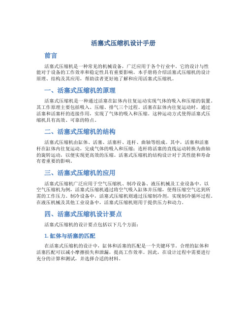
活塞式压缩机设计手册前言活塞式压缩机是一种常见的机械设备,广泛应用于各个行业中。
它的设计与性能对于设备的工作效率和稳定性具有重要影响。
本手册将介绍活塞式压缩机的设计原理、结构及其应用,帮助读者更好地了解和应用活塞式压缩机。
一、活塞式压缩机的原理活塞式压缩机是一种通过活塞在缸体内往复运动实现气体的吸入和压缩的装置。
其工作原理主要包括吸入、压缩、排气三个过程。
活塞在缸体内往复运动时,通过活塞和活塞杆的连接作用,实现了气体的吸入和压缩。
这种运动方式使得活塞式压缩机具有高效、可靠的特点。
二、活塞式压缩机的结构活塞式压缩机由缸体、活塞、活塞杆、连杆、曲轴等组成。
其中,活塞和活塞杆在缸体内往复运动,完成气体的吸入和压缩;连杆将活塞的直线运动转换为曲轴的旋转运动,以便实现更高效的压缩。
活塞式压缩机的结构设计对于其性能和寿命有着重要的影响。
三、活塞式压缩机的应用活塞式压缩机广泛应用于空气压缩机、制冷设备、液压机械及工业设备中。
以空气压缩机为例,活塞式压缩机通过将空气吸入缸体并压缩,使得压缩空气达到所需的工作压力。
制冷设备中,活塞式压缩机则通过压缩制冷剂,实现制冷循环过程。
在液压机械及其他工业设备中,活塞式压缩机则用于提供压力和动力。
四、活塞式压缩机设计要点活塞式压缩机的设计要点包括以下几个方面:1. 缸体与活塞的匹配在活塞式压缩机的设计中,缸体和活塞的匹配是一个关键环节。
合理的缸体和活塞匹配可以减小摩擦损失和泄漏,提高工作效率。
因此,在设计过程中需要进行充分的计算和测试,并选择合适的材料。
2. 活塞杆的设计活塞杆是将活塞与连杆连接的重要部件。
在活塞式压缩机的设计中,活塞杆的刚性和强度对于设备的安全运行和寿命至关重要。
设计时需要保证活塞杆的强度满足工作条件,并通过适当的润滑和冷却措施减小摩擦损失。
3. 连杆设计连杆是活塞与曲轴连接的关键部件。
在活塞式压缩机的设计中,连杆的设计要考虑到力学特性和可靠性。
合理的连杆设计可以减小振动和冲击,降低设备失效的风险。
压缩空气系统设计

压缩空气系统设计摘要:一个好的压缩空气系统设计对于半导体芯片厂是非常重要的。
这篇论文主要是介绍压缩空气系统的设计思路。
本文主要讲述一下内容: 总体目标、气体要求、扩充策略、维护保养、空气流通、气体品质与压力、系统中的压力损失、系统框架等。
关键字:压缩空气;压力;容量;质量abstract: a well designed compressed air system is very important for a semiconductor wafer fab operation. this paper gave the designer of compressed air system design. the following topics covered in this paper: overall objective, air demand, expansion strategy, maintenance considerations, ventilation, air quality, air pressure, pressure loss in air system, information needed by supplier, air receiver sizing, system layout. even you are designing a new compressed air system or you want to get your exist system expanded, you will find this paper is helpful for your project.key words: air compressor; pressure; capacity; quality compressed air system designi overall objective of compressed air system design meet average air demandmeet peak air demandprovides the quality of air needed for the applicationprovides at least the minimum required air pressure provide capability for future expansionprovide capability for easy maintenanceprovides sufficient ventilationkeep the project cost within budgetminimize operation costii air demandair demand can be determined from flow measurements or by observation of exist compressor load factors in an existing system. an air survey can be done on an existing system or for a proposed system to determine air demand. if an existing system has the compressors running at 100% use factor and is still not maintaining design pressure, plant required capacity chart located in this section can be used to determine how much additional capacity is required to bring the pressure back up to the design point.for example: if existing plant capacity is 2000 scfm, existing pressure is 90 psi, but the required pressure is 110 psi. we assume load factor is 100%,the additional capacity required for each 1000 scfm (existing) can be200scfm?? =400scfmdetermined in the chart : 200scfm/1000scfm. so the totaladditional capacity is :total required capacity is 2400 scfm, as shown in the above chart.iii expansion strategyone approach to future expansion requirements is to oversize the existing system. this may take the form of one or more compressors designed to run at less than full load to meet present demand allowing for increased air production in the future. it may also take the form of installing one or more additional compressors the are on standby until needed. another approach is to design the compressor room and piping system such that additional compression equipments can be added later.iv maintenance considerationsall compressors require routine preventive maintenance and nearly all compressors eventually experience an unexpected outage. if the cost to an outage is extreme, it is wise to consider a stand-by compressor in the system. when maintenance is required, it is necessary to have sufficient room to work on the compressor system. make sure there is enough clearance around and above the components to facilitate maintenance. minimum clearances can be obtained from the equipment supplier for specific item, overheadlifting capability is useful.if the compressor intake is located indoors, sufficient air must be available to pass through the intake filter and into the compressor. this need for ventilation, however, is minor compared to the ventilation required for removal of heat. it is generally true that:□an air cooled compressor rejects about 42.4 btu/min per bhp to the air around itself.□a water cooled compressor rejects between 13% and 30% of that amount (the rest is rejected to the cooling water). based on a 330 bhp compressor:get specific heat rejection data from the equipment manufacturer in order to determine ventilation requirement. the specific heat of air at 14.7 psia, 60deg f is 0.018336 but/cubic ft-deg f. in order to ventilate a room for a 330 bhp air cooled unit allowing a 10 deg f temperature rise in the cooling air would require the following;(330 x 42.4 btu/min)x(cubic ft-deg f/0.018336 btu)/(10 deg f)=76,309 cfm of ventilating airv air quality / pressurethe quality of is determined by it’s intended use. dewpoint requirements can be addressed with aftercoolers and dryers. oil content can be addressed with oil free compressors or filtration. particulate matter can be addressed with piping materials and filtration. refer to the manufacturer’s catalog to select the aftercooler, dryer and filter. determine air pressure requirements at the point of use. most air pressure requirements are satisfied by selection of the proper compressor design pressure and a properly designed piping system. low pressure requirements are often satisfied from the plant air system through a pressure regulator. when constant pressure is required at the point of use and normal system pressure fluctuations are a problem, a point of use pressure regulator is generally the solution. in this last case system pressure must be designed to always be above the desired pressure after the regulator.vi pressure loss in air systemsdetermine air pressure requirements at the point of use. most air pressure requirements are satisfied by selection of the proper compressor design pressure and a properly designed piping system. low pressure requirements are often satisfied from the plant air system through a pressure regulator, when constant pressure is required at the point of use and normalsystem pressure fluctuations are problem, a point of use pressure regulator is generally the solution. in this last case system pressure must be designed to always be above the desired pressure after the regulator.pressure loss in air systemspressure drops for components such as aftercoolers, dryers and filters should be obtained from the manufacturer. the expected pressure drop through the piping system can be estimated using the pressure loss tables and equivalent length table.vii information needed by supplierthe supplier should be given the following design conditions:barometer=psiainlet air temperature=deg frelative humidity=%cooling water temperature=deg f (if applicable) discharge pressure=psigair flow=icfm or acfm or scfmdefinitions:icfm - inlet cubic feet per minute. this is a measurementof the air entering the compressor.acfm - actual cubic feet per minute. this is measurement of actual air delivered, referred to inlet conditions. scfm-standard cubic feet per minute delivered. this is a measure of delivered capacity rapacity referred to some standard set of conditions. the most common set of standard conditions are 14.7psia, 60 deg f and 0% relative humidity. the supplier should also be given the minimum and maximum inlet air temperatures. if it is a water cooled application, minimum and maximum cooling water temperatures should also be stated.viii air receiver sizingthe air receiver size can be determined based on manufacturer’s recommendation or system requirements.the following formula can be used to size a tank based on system needs.v: receiver capacity, in cubic feett: compressor off line time prior to loading, in minutes p2: final receiver pressure when the compressor just be off ling, in psigp1: initial receiver pressure when the compressor starts, in psigc: actual compressor delivery, acfmpa: atmospheric pressure, psiaix system layoutthe following picture shows the general layout for compressed air system.作者简介:张榕,男,汉族,天津人;中级工程师,中芯国际集成电路制造(天津)有限公司,研究方向:机电/控制/洁净室。
压缩空气 (教学设计)-2024-2025学年科学三年级上册教科版

《压缩空气》一、教学目标学生能够理解空气占据一定的空间,且空气占据的空间可被压缩和扩张。
学生能够认识到压缩的空气具有弹性。
学会使用实验方法证实空气确实占据空间且可被压缩或扩张。
能够运用对比实验控制条件的方法进行观察,并准确记录实验结果。
通过对实验现象的分析,尝试从微粒的角度对空气的压缩和扩张现象进行解释。
在科学事实的基础上进行大胆预测和合理的解释,培养科学思维。
二、教学重难点教学重点通过实验探究,理解空气可以被压缩和扩张的特性,以及压缩空气具有弹性。
掌握对比实验的方法,能够准确观察和记录实验现象。
教学难点能够从微粒的角度解释空气为什么可以被压缩和扩张。
培养学生在实验过程中的合作能力和科学探究精神。
三、教学方法讲授法、实验法、讨论法、演示法。
四、教学准备学生分组实验材料每组两个完全相同的注射器、水、橙子皮、靶盘、学生活动手册。
教师演示材料多媒体课件、大尺寸注射器(便于演示实验)。
五、教学过程(一)创设情境,导入新课提问引入:教师展示水、空气、石块三种物体的图片,提问学生:“我们已经知道空气、水和石块都能占据空间,那么空气和水在占据空间方面有什么不同呢?”引导学生思考两者的差异,如空气看不见摸不着、水是液体等。
教师进一步追问:“那你们有没有想过,如果我们对它们施加压力,会发生什么呢?”激发学生的好奇心。
回顾旧知:通过提问,引导学生回顾之前学习的空气占据空间的知识,如将杯子倒扣在水中,杯子里的空气会阻止水进入杯子,使纸团保持干燥等实验。
教师可以用图片或动画的形式再次展示这个实验过程,加深学生对空气占据空间的理解。
教师提问:“从这个实验中,我们能看出空气在占据空间时有什么特点呢?”引导学生回答空气会占据一定的空间并且能阻止水进入。
引出课题:教师总结学生的回答后,引出本节课的主题:“今天我们来探究空气是否可以被压缩或扩张,进一步了解空气在占据空间方面的特性。
”教师可以展示一些生活中与压缩空气相关的图片,如打气筒、篮球等,让学生初步感受空气的可压缩性。
压缩空气处理系统,空气过滤器,压缩空气干燥器,气体净化系统说明书
Your compressed air - Our know-howcomponents and engineered systems for compressed air and gas treatmentComplete compressed air processing at a glance:Solid particles Pressure dew point Oil/oil vaporMeasured in accordance with ISO 8573-4, ref. conditions 14.5 psi [a] absolute, 68 °F, 0% RHMeasured in accordance with ISO 8573-3Measured in accordance with ISO 8573-2 and ISO 8573-5, ref. conditions 14.5 psi [a] absolute, 68 °F, 0% RH your single source of supply and quality you can rely on.BEKO Technologies, Corp.Social responsibilityIndependenceEmployee-oriented corporate cultureStrong and reliable partner TechnologyleaderEfficient use of resources We set the standard. With our expertise,our experience, and our passion.For more than three decades, BEKO Technologies has beendeveloping, manufacturing and selling high-quality, high-capacity and high-efficiency components and engineered systems for optimal compressed air and gas quality. Today, we offer acomplete range of products for all tasks related to compressed air and gas engineering, transportation, and processing.Judge us by our service and supportFor us, the best measure of all the things we do is the satisfactionof our customers. Your experience and requirements are the impulses that drive our innovations. Therefore, our constant readiness to enter into dialog and business partnership is very important to us. Our worldwide network of subsidiaries and experienced distributors ensure close and individualized customer support in all markets.What counts for us is confidenceReliability and honesty are the basis of a true partnership andrequirements in achieving a shared vision. As an independent company, BEKO Technologies stands for freedom of decision, professionalism, and consistency. We are focused on the concerns of our customers and partners, and are completely committed to achieving success together.Definitive quality products, cost effective, and innovativeConstantly evolving employment conditions and legal requirements create new and increased demands on compressed air and gastechnology. BEKO Technologies transforms these requirements into successful and practical products and system solutions. Thanks to this expertise, we are recognized worldwide as a major innovator in our sector.ProductsSystemsServicesFiltration and Separation with CLEARPOINT ®The CLEARPOINT ® filter technology guarantees low operating costs, long service life, outstanding process reliability, and the safe filtration of aerosols, oil and particles. This comprehensive range of products covers aperformance spectrum from 25 to 21,000 scfm and includes threaded and flanged filters, as well as high-pressure filters up to 7,250 psig.With our innovative eco filter elements and flow optimized, corrosion protected housing construction, CLEARPOINT ® offers safe and reliable filtration and qualitatively better compressed air at significantly reduced operating costs.Filtration done the energy-efficient way CLEARPOINT ®key features:The eco series filter elements of the CLEARPOINT ® offer significant energy savings at maximum filtration performance.Activated carbon adsorbers CLEARPOINT ® V activated carbon adsorbers for top compressed airquality with a low residual oil contentAir Treatment› High-performance filtration; better compressed air quality and significantly reduced operating costs › Improved separation efficiency› High dirt and particulate absorption capacity › Super-low differential pressure› Performance optimized volume flow increase by up to 30% › Tested and validated in accordance with ISO 12500 › Filters also available as water separators: CLEARPOINT ® WRefrigerant Drying with DRYPOINT ® RA and RA Eco SeriesThe operating costs - and not the investment costs - determine the cost efficiency of refrigeration dryers. Using DRYPOINT ® RA these crucialoperating costs can be reduced by half over a 5-year period. The non-cycling DRYPOINT ® RA line is available in two different series to satisfy every level of required performance.DRYPOINT ® RAc Economy Series from 10 to 480 scfm DRYPOINT ® RAx Premium Series from 20 to 10,000 scfmEfficiency pays offDRYPOINT ® RA key features:› Includes the patented Vario Flow hot gas by-pass valve › Compact design with low internal vibration› High efficiency heat exchanger for inlet temperatures up to 160 °F › BEKOMAT ®insideThe DRYPOINT ® RA Eco series takes all of the best features from thestandard RA series and combines them with innovative cycling and variable speed technology resulting in even greater operational cost savings. DRYPOINT ® RA CT with energy saving cold trap cycling technology DRYPOINT ® RA VSD with unique variable speed compressor and fanMaximum efficiency combined with cycling technology DRYPOINT ® RA Eco Series key features: › All new, ground-up controller design› Includes the patented Vario Flow hot gas by-pass valve › Oversized heat exchanger with flow optimized profile › BEKOMAT ® inside› Maximum energy savings through advanced cycling and variablespeed technologyAir TreatmentRefrigerant Drying with DRYPOINT ® RA HT and DRYPOINT ® RS HPDRYPOINT ® RA HT high temperature refrigerant air dryers arespecifically designed to handle the extreme demand of inlet compressed air temperatures up to 210 °F. This level of performance is only possible with the integrated after cooler and filter combination found within the DRYPOINT ® RA HT series dryers.Minimal pressure drop, low operating costs DRYPOINT ® RA HT key features: › Significantly reduced operating costs › High operational reliability› Includes the patented Vario Flow hot gas by-pass valve › BEKOMAT ® inside› Integrated after cooler complete with pre-filtrationWith full counter flow heat exchangers of either copper tube-in-tube or stainless steel / copper brazed plate designs, the DRYPOINT ® RS HP is capable of handling compressed air pressures up to 725 psig all while maintaining tight outlet pressure dew point tolerance.Refrigerant drying for high pressure systems DRYPOINT ® RS HP key features: › Additional stainless steel componentry › Very long service life › Advanced controller› High pressure rated BEKOMAT ® inside › Easy handling and installation ›Available in 17 different model sizesAir TreatmentHeatless Desiccant Drying with DRYPOINT ® XC and DRYPOINT ® AC HPDRYPOINT ® XC desiccant dryers are specifically designed to minimize air loss. With this design, air loss and back pressure are reduced resulting in an operationally efficient dryer. When these features are combined with the self-adjusting demands times of the premium models the result is a dramatically quick economic payback period. The DRYPOINT ® XC line is available in two series to suit every application.DRYPOINT ® XCe Economy Series from 80 to 800 scfm DRYPOINT ® XCp Premium Series from 80 to 2,800 scfmMinimal pressure drop, maximum savings DRYPOINT ® XC key features: › Significantly reduced operating costs › High operational reliability› Electronic control offers operational flexibility› Designed with the user in mind - easy install and simple maintenanceThe DRYPOINT ® AC HP desiccant dryer reliably removes humidity from high-pressure compressed air. Every DRYPOINT ® AC HP unitis individually adjusted to the application conditions and customer requirements and thereby achieves the utmost in performance efficiency.Drying under high pressureDRYPOINT ® AC HP key features: › Full stainless steel construction › Leak free connections› Intelligent, expandable PLC controller › Trouble-free and easy to maintain › Freeze-free purge air›Sized and engineered specifically for your applicationAir TreatmentHeated Desiccant Drying with DRYPOINT ® XF and DRYPOINT ® ACHHeated purge desiccant dryers provide the next level up in terms of energy savings when compared to heatless designs, and the DRYPOINT ® ACH is no exception. The entire design from valves to controller were given careful consideration to not only save money, but to also improve operational reliability.Optimized heated drying systems DRYPOINT ® ACH key features: › Purge efficient design › Fully programmable PLC › Standard cycle failure alarm› Available with or without tower insulation› Demand specific sizing and engineered to your exact specificationsWhen a true system solution that delivers absolute maximumperformance in all areas is required then DRYPOINT ® XF is that solution. Heated, blower operated desiccant dryers are at the top of the range in terms of product longevity, reliability and total energy savings. DRYPOINT ® XFe economy heated blower purge seriesDRYPOINT ® XFi ecoIntelligent heated blower auto-purge seriesWhen maximum efficiency is your goal DRYPOINT ® XF key features: › Auto-purge rate and user modes › Advanced ecointelligent PLC› Up to 90% energy savings compared with a conventional dryer › Available with or without tower insulation›Demand specific sizing and engineered to your exact specificationsDRYPOINT® XFFlowPressureAir TreatmentMembrane Drying with DRYPOINT ® MDe, MDp, and MDiThe DRYPOINT ® MD is a super compact membrane air dryer that dries compressed air or gas stream down to the required dew point while self-adjusting to the ambient conditions. Along with filtration, compressed air drying contributes significantly to the enhancement of process reliability. The DRYPOINT ® MD range is available without filtration as with thestandard series, with an integrated pre-filter in the DRYPOINT ® MDp series, and in the super energy saving, user adjustable MDi configuration.The Perfect OEM SolutionThe DRYPOINT ® MD range is available in a variety of configurations from a membrane bundle without housing, to simple tubular designs, all the way through to custom housing shapes and materials. Being that the technology is 100% engineered and produced by BEKO Technologies means that we can handle your project through the entire project life cycle - from concept to prototyping, from benchmarking to serialized production, we have the optimal solution.A solution for every application DRYPOINT ® MD key features:› Reliable compressed air drying with low purge air demands › Zero electrical consumption and no desiccant › TWIST 45 technology for high efficiency drying› No change in the compressed air composition or temperature › No moving parts and no maintenance› Optimum filtration included directly upstream of DRYPOINT ® MDp › DRYPOINT ®MDi with ecoIntelligent controllerAir TreatmentMeasurement Technology with METPOINT ® InstrumentationIn the field of compressed air, specialized measurement technologyprovides the database used for the successful assessment and assurance of compressed air quality. Continuous monitoring of compressed air parameters offers process safety and the reliable identification of hidden expenses that are driving up costs unnecessarily. Possible overloading (i.e. excessive air velocities) or malfunctions can be detected quickly and reliably and this allows for the most economical optimization of plant components. Moreover, the exact consumption percentages at different stages of production is of great value in making fact-based businessmanagement decisions. The complete METPOINT ® line of monitors, data loggers and sensors let you handle these tasks with ease:A synergistic effectMETPOINT ® key features:› Highly accurate instruments designed for compressed air › Reliable measurements that are independent › Multi-function displays that are easy to use › Completely modular system that expands as needed › Maximum flexibility with stationary and portable devices ›No adjustments necessaryInstrumentationHydrocarbon Measurement Technology with METPOINT ® OCVAt many points in the processing of compressed air, there is therisk of contamination with hydrocarbons, particularly oil. In oil flooded compressors, oil vapor enters the compressed air system as a result of the compression process. Further contamination can occur where oil and grease are employed as lubricants and sealing compounds. Even oil-free compressors are no guarantee for oil-free compressed air, since oil vapor already exists in the air that is drawn into the compressor at the intake. Wherever contaminants may enter a production process, then the company needs to be sure that accurate monitoring is in place to detect even the smallest trace of contamination. The METPOINT ® OCV and OCV compact completely takes over the requirement to constantly monitor your compressed air and performs this task to an accuracy of 0.003 mg/m³. The system ensures that you have contamination-free processes and thereforecontamination-free products.Two devices in oneMETPOINT ® key features: › Worldwide exclusive technology › Exceeds ISO 8573-1 Class 1 standards › Self-adjusting reference air sample› Simplified calibration process eliminates downtime › Network ready with data logging and remote access › Multi-function color touch screen display ›Mobile monitoring system availableInstrumentationOil-free Process Technology with BEKOKAT ®The main source for oil in compressed air is the compressor: some of the compressor oil from oil-lubricated machines always enters the compressed air stream. In order to prevent this, the installation of compressors with oil-free compression is often favored. This is a false sense of security! This compression method prevents additional lubricating oil from entering the compressed air, but, this is by no means a guarantee that the compressed air is free from oil. Hydrocarbons in the ambient air are the reason for this.Hence, compressed air of the highest quality according to ISO 8573-1 can only be guaranteed with oil-free compression combined withsupplementary processing. The BEKOKAT ® offers an ideal system solution for this! In a single process step, the BEKOKAT ® breaks down hydrocarbons inside the compressed air stream. The residual oil content significantly outperforms the requirements of Class 1 according to ISO 8573-1 - proven and certified!Trendsetting catalysis technology BEKOKAT ® key features:› Oil-free and sterile compressed air that is better than ISO 8573-1Class 1 oil content standard› Independent of ambient temperature, air humidity and oil inlet concentration› Clean and environmentally friendly › Partial-load operation is possible›Minimal maintenance with long service intervalsProcess TechnologyCondensate Drainage with BEKOMAT ®Generating compressed air always involves the formation of liquid condensate which, in most cases, contains oil. It is also contaminated with dirt particles which, if not removed, will disperse throughout an entire compressed air network. This is a very common problem and often results in elevated costs, damage and downtime. Using an electronically level-controlled BEKOMAT ® the condensate in the compressed air system is drained automatically. The intelligent electronics preventcompressed air losses and minimize the energy input required. The return-of-investment installing a BEKOMAT solution is usually less than 6 months.Process-safe, reliable and efficient BEKOMAT ® key features:› Unique sensor detects all kinds of condensate › High dirt resistance › Low maintenance › Fully automatic monitoring› Saves energy, costs and lowers CO 2 emissions›Extensive portfolio of custom equipment for special applicationsCondensate TechnologyCondensate Processing with ÖWAMAT ®, QWIK-PURE ® and BEKOSPLIT ®Located directly at the source, oil-water separation is a morecost-effective solution for environmentally compatible condensate management than centralized treatment. The ÖWAMAT ® andQWIK-PURE ® oil-water separators do not generate any energy costs, boast enormous filter service lives and can be retrofitted without problems in older facilities.Sustainability with a savings potentialÖWAMAT ® and QWIK-PURE ® key features:› Processed condensate can be directly introduced into the sewer system as treated wastewater› Easiest handling through cartridge technology › Type approval for compressor condensates› No permit required according to most local laws on water quality › No energy costs under normal conditionsBEKOSPLIT ® emulsion splitting systems reliably and cost-effectively remove oils, water-insoluble organic impurities and solid contaminations from condensate. BEKOSPLIT ® operates with low splitting-agent consumption, longer filter service life and offers electronic monitoring of the operating conditions.Environmentally friendly and cost-effective BEKOSPLIT ® key features:› Economical in consideration of purchase, operation, and maintenance › Reliable, environmentally friendly and easy to use › Type approval according to German standards›No permit required according to most local laws on water qualityCondensate TechnologyReliable|Efficient|Innovative What can we do for you?BEKO TECHNOLOGIES CORP.900 Great Southwest Pkwy SWAtlanta, GA 30336USAPhone + 1 (404) 924-6900。
火力发电厂仪用、厂用压缩空气系统设计技术导则
火力发电厂仪用、厂用压缩空气系统设计技术导则压缩空气系统是火力发电厂仪用和厂用的重要系统之一,其设计技术的优劣直接影响着发电厂的运行效率和设备寿命。
本文旨在为火力发电厂压缩空气系统的设计提供生动、全面且有指导意义的技术导则。
首先,在设计火力发电厂仪用、厂用压缩空气系统时,需要考虑系统的稳定性和可靠性。
稳定性保证了内部压力和流量的恒定,可靠性保证了系统的持续工作。
为此,应选择高质量的压缩机、过滤器和干燥器,并进行定期的维护保养,以确保系统的可靠性和稳定性。
其次,在选择压缩机时,应根据火力发电厂的压缩空气需求进行合理选择。
根据需要的压力、流量以及噪音和振动要求,选择适合的离心式压缩机或螺杆式压缩机。
此外,还应考虑压缩机的能耗和效率,选择能效比高的压缩机,以降低能源消耗和运行成本。
再者,在设计压缩空气系统时,应合理布置管道和安装压力调节器。
管道布局应简洁明了,避免过多的转弯和阻力。
同时,应合理安装压力调节器,以确保系统中各个设备的工作压力符合要求,避免设备过压或低压工作导致的故障。
另外,系统的附属设备也需要重视。
过滤器和干燥器的选择和定期维护是保证系统正常运行的关键。
过滤器能够有效地去除空气中的尘埃和杂质,避免对设备产生损坏,干燥器可以除去空气中的湿气,防止腐蚀和锈蚀的产生。
因此,选择高效的过滤器和干燥器,并定期检查和更换滤芯和脱水剂,可以有效延长设备的使用寿命。
最后,针对火力发电厂压缩空气系统的安全性和节能性问题,应加强管理和监控。
制定系统的操作规程和维护计划,对设备进行定期巡检和维护,及时清理积灰和清洗设备。
并加强对操作人员的培训和技能提升,提高操作人员对系统的认识和技术水平。
此外,可以考虑采用智能监控系统,实时监测系统的运行状态,及时发现问题并进行处理,以提高系统的安全性和节能性。
综上所述,火力发电厂仪用、厂用压缩空气系统的设计技术导则包括系统稳定性和可靠性的考虑、压缩机的选择、管道布局和附属设备的选择与维护、安全性和节能性的管理与监控。
压缩机设计手册_5

于!",除检验零、部件的装配质量和容积流量自动调节装置、安全阀的灵敏性外,还应在额定排气压力下做下列试验:#)测量实际容积流量;$)测量排气压力;%)测量排气温度;&)测量轴功率。
测得的结果应符合本标准及有关技术文件的规定。
!标志、包装和贮存!"#每台滑片空压机均应在平坦且醒目的部位设置产品铭牌。
铭牌尺寸按’()* +,,-.—+//+的规定。
铭牌上至少应标出下列内容:#)产品型号;$)产品名称;%)公称容积流量,单位为0,)012;&)额定排气压力,单位为34#;5)轴功率或驱动机功率,单位为67;8)转速,单位方9)012;:)外形尺寸(长;宽;高),单位为012;")净重,单位为6:;1)出厂编号;<)出厂年月;6)制造厂名称及所在地(出口产品应加标“中华人民共和国”字样)。
!"$滑片空压机应设置表明其旋转方向的标志。
!"%滑片空压机的包装和收发货标志应符合’()*+,,=>—+//!及’()*.,==—+/=.的规定;出口产品应符合有关标准的规定。
!"&滑片空压机附带的易损件、备件、专用工具和附属设备的外露加工表面应在涂防锈油后加以包装,并固定在箱中。
随机文件应妥善包装,放在机组箱内。
!"#滑片空压机的零件、部件、成品、附属设备及配套机电设备等应存放在干燥、通风的库房或有遮盖的不至受潮的场所内。
!"$在正常的储运条件下,制造厂应保证产品自发货之日起,至少在一年内不致因包装不良而引起锈蚀、霉损等,特殊情况按供需双方协议执行。
压缩空气系统URS

压缩空气系统用户需求书User Requirement Specification文件变更控制1.目的为我公司和供应商提供压缩空气系统的设计、制造、采购、验收和确认依据。
该文件旨在从项目和系统的角度阐述公司的需求,这份文件是构建起项目和系统的文件体系的基础,供应商必须指出他的标准与该用户需求标准的符合性。
同时也是系统设计和确认/验证的可接受标准的依据2. 范围及职责本URS适用于压缩空气系统。
需方对本URS的编制质量负责,供方严格按照本RUS所明确的法规标准、技术要求、服务要求,提供相关设备设施和服务,供方须对需方所提供的URS负保密责任。
3.法规和国家标准该设备用于为部分制药生产设备提供空气动力,必须符合GMP规范、国家及行业标准和本公司管理要求。
3.1 GMP法规●《《药品生产质量管理规范 (2010修订)》(中华人民共和国卫生部令第79号)3.2国家及行业标准●GB-8196-87机械设计防护罩安全要求●GB-52261-2002机械安全机械电气设备第一部分:通用技术条件●GB-12265-90机械防护安全要求●2010年版《中国药典》●国家相关消防安全法律法规要求4.3公司管理要求●《设备管理规程》、《质量风险管理规程》、《压缩空气系统管理规程》4.项目介绍4.1 项目描述根据公司制药生产要求,天德制药生产部需新购压缩空气系统,用于为设备提供空气动力及制药用气。
4.2 工艺或流程描述空压机制得的压缩空气经储气罐、冷干机、四级过滤器后得到符合GMP要求的洁净压缩空气后,经压缩空气管道输送到车间各用气点5.技术要求●URS02厂房设施及公用系统要求●URS03对设备自身的要求●URS04电气自控要求●URS05 QA要求●URS06维修服务要求●URS07清洗消毒要求●URS08环境健康安全要求●URS09生产工厂验收测试要求●URS10包装运输要求●URS11文件资料要求●URS12备品零件要求●URS13现场验收要求●URS14安装要求●URS15培训要求●URS16其它要求。
压缩空气站设计规范 (2)

压缩空气站设计规范1. 引言压缩空气站是用于将大气中的空气通过机械手段进行压缩和净化处理,以满足不同工业领域的需求。
本文档旨在提供一套设计规范,以确保压缩空气站的设计满足安全、高效、可靠等要求。
2. 设计要求2.1 安全要求•设计应满足相关国家安全标准和法规要求,包括但不限于国家标准《压缩空气站设计规范》、《压缩空气站安全操作规程》等;•设备应具备过载保护、故障自动停机、安全阀等安全装置,并定期检测和维护;•设计应考虑员工安全操作空间、防护措施和紧急疏散通道等方面的要求;•要有完善的泄漏检测与处理系统,确保压缩空气站的环境保护及员工健康。
2.2 性能要求•设计应能满足用户需求,根据不同工业领域需求进行参数定制,如压力范围、流量等;•设计应考虑能耗和效率的平衡,提供节能优化方案;•设计应考虑系统的可靠性和稳定性,减小故障率和停机时间。
2.3 操作和维护要求•设计应易于操作和维护,提供清晰明了的操作界面和维护手册;•设备和系统应具备远程监控和诊断功能,方便运维人员进行远程操作和故障排除;•每个操作步骤都应提供相应的标识,以确保正确操作。
3. 设计准则3.1 压缩机选择•根据用户需求和工艺特点,选择合适的压缩机类型,如活塞式、螺杆式、离心式等;•压缩机的选择应综合考虑容量、效率、噪音、维护等方面的因素。
3.2 空气处理系统•设计应提供多级空气处理系统,包括除尘、除湿、降温等步骤,以保证出口空气质量满足用户需求;•空气处理系统的设计应结合实际工艺要求和环境条件,选择合适的过滤器、干燥器、冷却器等设备;•设计应考虑系统中的维护和更换设备的便利性。
3.3 储气罐设计•储气罐应根据用户需求和系统工况确定合适的容量和工作压力;•设计时应考虑储气罐的安全阀、液位计、排水系统等设备,并进行适当安装;•储气罐的材质和防腐措施要求符合相关标准和法规。
3.4 控制系统•控制系统应具备自动控制和远程监控功能,包括压力、温度、流量等参数的实时监测和调节;•设计应考虑系统的可靠性和容错性,具备故障自动检测、报警和自动切换等功能。
- 1、下载文档前请自行甄别文档内容的完整性,平台不提供额外的编辑、内容补充、找答案等附加服务。
- 2、"仅部分预览"的文档,不可在线预览部分如存在完整性等问题,可反馈申请退款(可完整预览的文档不适用该条件!)。
- 3、如文档侵犯您的权益,请联系客服反馈,我们会尽快为您处理(人工客服工作时间:9:00-18:30)。
压缩空气中水分的含量及影响( )一般大气中的水份皆呈气态,不易觉察其存在,若经空气压缩机压缩及管路冷却后,则会凝结成水滴。
[例如]在大气温度30℃,相对温度75℃状况下,一台空气压缩机,吐出量为3m3/min,工作压力为0.7Mpa,运转24小时压缩空气中约含有100升的水份。
压缩空气系统中水分的影响:一、压缩空气管路快速腐蚀,压降增加;设定压力提高1kgf/cm2G,动力输出增加5%-7%,或减少排气量6%-8%。
二、设备严重故障,增加维修保养费用;1.腐蚀零件。
2.阻塞气控仪器。
3.降低气动工具的效率。
三、破坏产品品质,产品不良率提高;1.应用产品清洁时,造成湿气污染。
2.应用喷漆涂装时,影响产品品质。
四、影响生产流程,生产能量降低;1.粉体输送时,易阻塞管线。
2.气动设备故障,而停工。
----冲刷掉气动工具,电机和气缸中的润滑油,增加磨损并缩短寿命,提高维护成本----使气动阀门和控制仪器失灵,影响可靠操作,效率降低----影响油漆和整饰作业质量----引起系统中的金属装置腐蚀生锈,影响其寿命,并可导致过度压降----气流分配成本提高(需倾斜管道,设置U形管和滴水管)----在冰冻季节,水气凝结后会使管道及附件冻结而损害,或增加气流阻力,产生误动压缩空气中油的危害:在一些要求比较严格的地方,比如气动控制系统中,一滴油能改变气孔的状况,使原本正常的自动运行的生产线瘫痪。
有时,油还会将气动阀门的密封圈和柱要胀大,造成操作迟缓,严重的甚至堵塞,在由空气完成的工序中,如吹形件,油还会造成产品外形缺陷或外表污染。
* 油污的主要来源由于大部分压缩空气系统都使用油润滑式压缩机,该机在工作中将油汽化成油滴。
它们以两种方式形成:一种是由于活塞压缩或叶片旋转的剪切作用产生的所谓“分散型液滴”,其直径在1-50um。
另一种是在润滑油冷却高温的机体时,汽化形成的“冷凝型液滴”,其直径一般小于1um,这种冷凝油滴通常占油污重量超过50%,占全部油污实际颗粒数量超过99%。
* 无油压缩机是否含油污在最理想的工作状态下,此类压缩机也会产生不少于0.5ppm W/W的碳氢化合物,即按100scfm气量计,每月产生的汽化冷凝液也超过15ml.氧化铝和分子筛的比较( )吸附剂特性氧化铝分子筛价格较低较高平均再生气量15%20~25%吸附特性相对湿度较高,吸附能力越强,效果越好相对湿度与吸附能力变化不大露点温度10min=-40℃4 min=-70℃-70℃再生特性相对湿度越低,再生风量越少,效果越好相对湿度越低,再生风量须较大,效果不佳使用寿命最少三年相同操作成本由于再生风量较小,故操作成本较低再生风量较大,操作成本较高吸附剂需求量较少较多耐热度低高(≤ 320℃)粒径 (mm)Φ3~5(4Å)Φ3~5(4Å)堆密度(g/ml)0.7>0.65静态吸附(%wt)10%相对湿度≥660%相对湿度≥1660%相对湿度≥18100%相对湿度≥32比表面积(m3/g)≥300>300孔容积(ml/g)≥0.38≥0.38磨耗(%wt)≤0.4≤0.38抗压强度(N)≥80≥70比较说明:①比表面积及孔容积较大者吸得较多。
②堆密度说明在相同的吸附工况下,较大者的吸附床层的容积可以较小。
③静态吸附量在相对湿度为60%时,大者可以减少吸附床层的容积。
④磨耗率较低者或抗压强度较大者使用寿命较长。
比较结论:优劣互见!请根据所需露点要求选择合适吸附剂种类!注:①压力强度(硬度)易会随着特殊添加剂而改变。
②氧化铝:吸得多,吸不干;分子筛:吸得少,吸得干。
故露要求较严格时下层70%采用氧化铝,上层30%采用分子筛。
③PSA(压转式)多采用氧化铝,TSA(热转式)多采用分子筛<<返回气压力露点参数及压缩空气质量等级( )◆ISO8573.1质量等级质量等级固体杂质(最大颗粒尺寸)μ最大压力露点°C(°F)含油量(油滴、油雾、油蒸汽)ppm w/w (mg/m3)1 0.1 -70(-94) 0.008(0.01)2 1 -40(-40) 0.08(0.1)3 5 -20(-4) 0.8(1)4 15 3(37.4) 4(5)5 40 7(44.6) 21(25)6 10(50)◆大气露点与压力露点相互对应数据由大气露点查相应压力下的压力露点大气露点°C空气压力MPa(绝压)0.1013 0.4 0.5 0.6 0.7 0.8 0.9 1.0-100 -100 -93 -91.8 -90.8 -90 -89.3 -88.6 -88 -90 -90 -82.2 -81.5 -79.7 -78.8 -78 -77.2 -76.6 -80 -80 -71.3 -69.8 -68.6 -67.5 -66.6 -65.8 -65 -70 -70 -61.7 -58.7 -57.3 -56.1 -55.1 -54.2 -53.4 -60 -60 -49.4 -47.2 -46 -44.7 -43.5 -42.5 -41.6 -50 -50 -38.3 -36.3 -34.6 -33.2 -31.9 -30.8 -29.8 -40 -40 -27.2 -25 -23.3 -21.6 -20.2 -19 -17.9 -30 -30 -16.1 -13.6 -11.6 -9.9 -8.1 -7 - 5.7 -20 -20 -4.8 -2.2 0 2.2 4 5.7 7.2 -10 -10 7.3 10.6 13.4 15.8 17.9 19.8 21.5 0 0 20.5 24.2 27.2 29.9 32.2 34.3 36.2 10 10 32.3 36.3 39.7 42.4 45.2 47.5 49.6压力露点°C空气压力MPa(绝压)0.4 0.5 0.6 0.7 0.8 0.9 1.0-70 -78.8 -80.2 -81.3 -82.2 -83 -83.7 -84.3 -60 -69.7 -71.2 -72.4 -73.4 -74.3 -75 -75.7 -50 -60.6 -62.2 -63.6 -64.7 -65.6 -66.4 -67.1 -40 -51.6 -53.3 -54.7 -55.9 -56.9 -57.8 -58.6 -30 -42.5 -44.4 -46 -47.3 -48.4 -49.3 -50.2 -20 -33.6 -35.6 -37.3 -38.7 -39.8 -40.9 -41.8 -10 -24.6 -26.8 -28.6 -30.1 -31.4 -32.5 -33.50 -15.7 -18.1 -20 -21.6 -23 -24.2 -25.210 -7.7 -9.5 -12.5 -14.2 -15.7 -16.9 -18压力换算表及压力比较表( )◆压力换算表(kg/cm2-mmHg) kg/cm20.1 0.2 0.3 0.4 0.5 0.6 0.7 0.8 mmHg73.6 147.1 220.7 294.2 367.8 441.3 514.9 588.4kg/cm20.9 1.0 1.2 1.4 1.5 1.6 1.8 2.0 mmHg662.0 735.6 882.7 1029.8 1103.3 1176.9 1324.0 1471.1(psi-mmHg)psi 1 2 3 4 5 6 7 mmHg51.7 103.4 155.1 206.9 258.6 310.3 362.0psi8 9 10 15 20 25 30 mmHg413.7 465.4 517.1 775.7 1034.3 1292.9 1551.4◆压力比较表MPa kg/cm2psi bar atm mHg inHg mAg ftAq1 10.20 145.0 10.0 9.87 7.50 295.3 102.0 334.6 0.098 1 14.2 0.98 0.97 0.74 29.0 10.0 32.80.1 1.02 14.5 1 0.99 0.75 29.5 10.2 33.5 0.101 1.03 14.7 1.01 1 0.76 29.9 10.3 33.9 0.133 1.36 19.3 1.33 1.32 1 39.4 13.6 44.6 0.0034 0.035 0.49 0.034 0.033 0.025 1 0.35 1.13 0.0098 0.10 1.42 0.098 0.097 0.074 2.90 1 3.28 0.0030 0.030 0.43 0.030 0.029 0.022 0.88 0.30 1缩空气净化系统配置方案( )常规压缩空气系统配置一般保护性用途空气品质符合ISO8573.1:质量等级2.-.4·去除大量水份和固态杂质·一般保护性用途·其他高效率过滤器A级之前置过滤器·冷冻式干燥机必备之前后置过滤器空气品质符合ISO8573.1:质量等级1.-.2·可取代无油式空压机·高品质空气源。
·吸附式干燥机必备之前后置过滤器。
· H级活性碳过滤之前置过滤无油空气源器。
低露点系统空气品质符合ISO8573.1:质量等级1.4.1压力露点可达 +2°C。
·无油无水高质量空气源。
·冷冻式干燥机前后置过滤器标准配备。
·活性碳过滤器为选择性或特殊配备空气品质符合ISO8573.1:质量等级1.-.2·可取代无油式空压机·高品质空气源。
·吸附式干燥机必备之前后置过滤器。
· H级活性碳过滤之前置过滤器。
无油空气源食品饮料级压缩空气系统配置图说明:1.蒸汽过滤器由下方和主管路相连2.安装后先不要装过滤器通风24小时后(同时轻敲管道以让碰头碎碴落下)再装上滤芯,灭菌后使用。
3.出口温度须降到35℃以下,以免油份变成油蒸气,不利达到无油状态。
压缩空气中油的危害:在一些要求比较严格的地方,比如气动控制系统中,一滴油能改变气孔的状况,使原本正常的自动运行的生产线瘫痪。
有时,油还会将气动阀门的密封圈和柱要胀大,造成操作迟缓,严重的甚至堵塞,在由空气完成的工序中,如吹形件,油还会造成产品外形缺陷或外表污染。
* 油污的主要来源由于大部分压缩空气系统都使用油润滑式压缩机,该机在工作中将油汽化成油滴。
它们以两种方式形成:一种是由于活塞压缩或叶片旋转的剪切作用产生的所谓“分散型液滴”,其直径在1-50um。
另一种是在润滑油冷却高温的机体时,汽化形成的“冷凝型液滴”,其直径一般小于1um,这种冷凝油滴通常占油污重量超过50%,占全部油污实际颗粒数量超过99%。