Network and Data Communication cha5-6
计算机网络Chapter5-cut
Sender:
treat segment contents
Receiver:
compute checksum of received
maybe errors nonetheless?
More later ….
5: DataLink Layer
5-7
Checksumming: Cyclic Redundancy Check
view data bits, D, as a binary number choose r+1 bit pattern (generator), G goal: choose r CRC bits, R, such that
5: DataLink Layer
5-14
Channel Partitioning MAC protocols: TDMA
TDMA: time division multiple access
access to channel in "rounds"
each station gets fixed length slot (length = pkt
trans time) in each round unused slots go idle example: 6-station LAN, 1,3,4 have pkt, slots 2,5,6 idle
5: DataLink Layer
5-15
Channel Partitioning MAC protocols: FDMA
network05

ִx represents the transmission medium
T - twisted pair cable F - fiber-optic cable a number - maximum length
by allowing data targeted to the other side of the bridge to pass
ִeffectively breaks an Ethernet network into two segments ִalso used to connect an Ethernet network to other types of network
Chapter 5 Ethernet
5.1 Ethernet NIC (3/3)
Wireless NIC ִis NOT an Ethernet NIC ִaccess method is CSMA/CA ִwireless NIC standard
IEEE 802.11.
Bridge ִjoins dissimilar networks
increases chance of collisions
ִhalf-duplex
Chapter 5 Ethernet
5.2 Evolution of Ethernet (3/5)
Bridge ִcan learn which devices are on each side ִlimits the traffic within one side
Communication Networks -11 -Network Layer

Module4 StandardsLesson11 Network LayerIn any network the user is outside the network and hence is not a part of it. In data communication the user terminals are called Data terminating equipment (DTE). The network nodes to which DTEs are connected are called Data Circuit terminating Equipment (DCE). In case of a telephone network, the DCE is an ordinary telephone exchange. In data network, it is a packet switch which is, or rather has to be, a computer. The job of the DCE is routing, packet assembly /disassembly, header generation, header changing, path selection etc. The network may consist of a central switch which serves the DCEs.For efficient working of the network a network layer protocol is required. ITU specified network layer protocol is X.25. Earlier X.25 supported both Connection Oriented (CO) Service and Connectionless (CL) Service, but it gradually became more CO oriented. X.25 is a continuous protocol, which allows:Page : Lesson 11.11. User-DCE communication2. DCE-User communicationThe communication between two DCEs which is internal to the network may follow any protocol transparent to X.25. The internal network protocol identifies the operation of the network. But the DCE to user protocol has to be standard so that a particular terminal can become compatible with any network. The DCEs are not routers. In fact there is not much to route inside a network. The switch shown in figure 1 is also a DCE that is not connected to any user.A real network consists of several subnets. The interconnection betweenthese subnets requires a Gateway. It may be single/ central to the network, or individual subnets may have their own gateways. Here, in this network routing is necessary between different subnets. The Gateways are called Routers. The difference between a DCE and a Router is that the former is directly connected to the user, whereas no user is connected to the Router. Signaling between User ↔ Network and Network ↔ Network are different.Router routes data not between paths but between NetworksX.25 helps the user to access the network. So it is basically an access protocol.X.25 is costly protocol so we may not implement it for each user. Also in remote places, a DCE may not be available to each user. PAD (Packet Assembler & De-assembler) is then used to connect the users to the network. The PAD is connected to a suitable DCE. PAD may be internal or external to the network as shown in figure 1. The user to the PAD is a local call. Using PAD necessitates that we use additional protocols such asPage : Lesson 11.21. User to PAD protocol2. PAD protocol3. PAD to DCE protocolThe Internet Service Providers (ISP) connects the network to the Internet. One of the DCEs or the router of the network is connected to the ISP. To become part of the Internet a network must be connected to the Internet. The ISP provides the required connectivity. A single ISP may be connected to several networks.The network layer handles packets. In case of CL Service networks each packet should have the full source-destination address. CO Service may be used with lesser addressing overheads.ITU physical layer protocol for all digital networks is X.21. An alternative protocol RS-232 provides an interface between both analog and digital networks, as a result, it is more popular.Actually the X.25 protocol is for the network layer only. Normally it is used with LAP.B in data link layer and X.21 at the physical layer. This whole set is conventionally referred to as X.25.LAP.B is a subset of HDLC, which works in the balanced mode of operation.In the original ISO document the network layer was termed as Packet level, since it handles packets. Similarly the Datalink and physical layers were called the Frame level and the Physical level.Page : Lesson 11.3Objective Questions11.01Subjective Questions11.11Level 2 Questions11.21Page : Lesson 11.4。
通信技术类英文文献
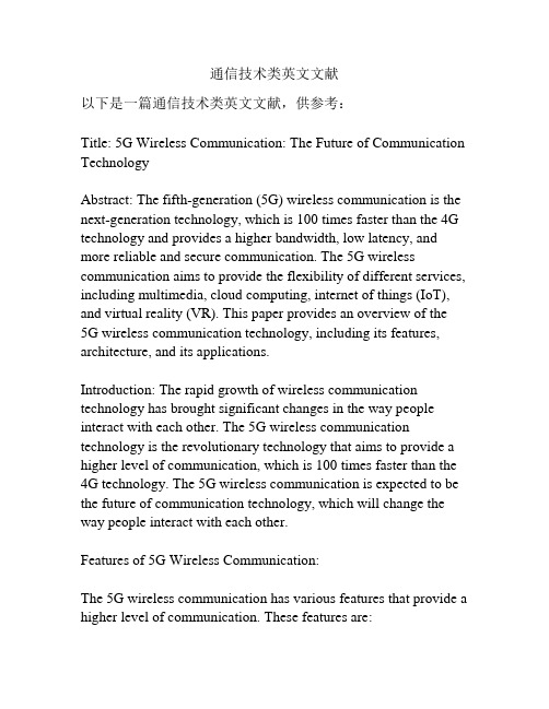
通信技术类英文文献以下是一篇通信技术类英文文献,供参考:Title: 5G Wireless Communication: The Future of Communication TechnologyAbstract: The fifth-generation (5G) wireless communication is the next-generation technology, which is 100 times faster than the 4G technology and provides a higher bandwidth, low latency, and more reliable and secure communication. The 5G wireless communication aims to provide the flexibility of different services, including multimedia, cloud computing, internet of things (IoT), and virtual reality (VR). This paper provides an overview of the5G wireless communication technology, including its features, architecture, and its applications.Introduction: The rapid growth of wireless communication technology has brought significant changes in the way people interact with each other. The 5G wireless communication technology is the revolutionary technology that aims to provide a higher level of communication, which is 100 times faster than the 4G technology. The 5G wireless communication is expected to be the future of communication technology, which will change the way people interact with each other.Features of 5G Wireless Communication:The 5G wireless communication has various features that provide a higher level of communication. These features are:1. High Bandwidth: The 5G wireless communication provides a high bandwidth, which increases the data transfer rate. This high bandwidth provides a better experience for multimedia services, such as streaming video, music, and gaming.2. Low Latency: The 5G wireless communication provides a lower latency, which improves the response time of the communication. This low latency is ideal for real-time applications such as autonomous vehicles, AR/VR, and remote surgeries.3. Massive IoT: The 5G wireless communication supports a large number of IoT devices with a higher density of devices per unit area. This feature enables the functionality of IoT applications in various industries, such as smart homes, smart cities, and healthcare.4. Network Slicing: The 5G wireless communication provides network slicing, which enables the partitioning of the network into multiple virtual networks. This feature provides the flexibility to provide different services with different requirements such as high speed, low latency, and high reliability.5. Security: The 5G wireless communication provides a higher level of security for communication. This security is provided through various features such as authentication, encryption, and privacy.Architecture of 5G Wireless Communication:The 5G wireless communication has a different architecture thanthe previous generations of wireless communication technology. The architecture of the 5G wireless communication is divided into three layers: the user plane, the control plane, and the management plane.1. User Plane: The user plane is responsible for the transmission and reception of user data. This layer involves the transmission and reception of user data through the radio access network (RAN) and the core network.2. Control Plane: The control plane is responsible for controlling the signaling messages between the user equipment (UE) and the network. This layer involves the control of signaling messages related to call setup, call tear down, and mobility management.3. Management Plane: The management plane is responsible for the management of the network resources and the configuration of the network. This layer includes the management of the network functions such as orchestration, automation, and telemetry.Applications of 5G Wireless Communication:The 5G wireless communication has various applications, which will have a significant impact on different industries. Some of the applications are:1. Smart City: The 5G wireless communication enables the functionality of smart city applications such as smart transport, smart parking, and smart street lighting.2. Healthcare: The 5G wireless communication provides a higher level of healthcare with the use of various applications such as telemedicine, remote surgery, and health monitoring.3. Industrial Internet of Things (IIoT): The 5G wireless communication enables the functionality of IIoT applications such as predictive maintenance, asset tracking, and real-time manufacturing process monitoring.4. Agriculture: The 5G wireless communication provides the functionality of precision agriculture applications such as intelligent irrigation, crop monitoring, and farm automation.Conclusion:The 5G wireless communication is the next-generation technology, which is expected to be the future of communication technology. The 5G wireless communication provides a higher level of communication with its features such as high bandwidth, low latency, and massive IoT. The implementation of the 5G wireless communication will have a significant impact on different industries such as healthcare, smart city, and IIoT.。
计算机专业英语的课文与翻译
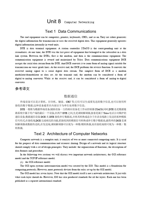
Unit 8 Computer NetworkingText 1 Data CommunicationsThe end equipment can be computers, printers, keyboards, CRTs, and so on.They are either generates the digital information for transmission or uses the received digital data. This equipment generally operates digital information internally in word units.DTE is data terminal equipment. A station controller STACO is the corresponding unit at the secondaries. At one time, the DTE was the last piece of equipment that belonged to the subscriber in a data link system. Between the DTEs, first is the modem, and then is the communications equipment. The communication equipment is owned and maintained by Telco. Data communications equipment DCE accepts the serial data stream from the DTE. And DCE converts it to some form of analog signal suitable for transmission on voice-grade lines. At the receive end, the DCE performs the reverse function. It converts the received analog signal to a serial digital data stream. The simplest form of DCE is a modem modulator/demodulator or data set. At the transmit end, the modem can be considered a form of digital-to-analog converter.While at the receive end, it can be considered a form of analog-to-digital converter.参考译文数据通信终端设备可以是计算机、打印机、键盘、CRT等;它们可以生成要发送的数字信息,也可以使用所接收的数字数据;这种设备通常在内部以字为单位处理数字信息;DTE一般称为数据终端设备;辅助设备一方的相应设备是工作站控制器STACO;同时,DTE也是数据链路系统中属于用户端的最后一个设备;在两个DTE之间,先是调制解调器,接着是属于Telco电话公司维护的通信设备;数据通信设备DCE从DTE接收串行数据流,并将其转换成适合于在语音线路上发送的某种模拟信号形式;在接收端,DCE完成相反的功能,把接收到的模拟信号转换成串行数字数据流;最简单的DCE是调制解调器或数据传送机;在发送端,调制解调器可以视为一种数/模转换器,而在接收端则可视为一种模/数转换器;Text 2 Architecture of Computer NetworksComputer network is a complex unit, it consists of two or more connected computing units. It is used for the purpose of data communication and resource sharing. Design of a network and its logical structure should comply with a set of design principles. They include: the organization of functions, the description of data formats and procedure.In the following two sections we will discuss two important network architectures, the OSI reference model and the TCP/IP reference model.(1)the OSI reference modelThe OSI open systems interconnection model was created by the ISO. This model is a foundation for comparing protocols; However, more protocols deviate from the rules set up by the OSI model.The OSI model has seven layers. Note that the OSI model itself is not a network architecture.It just tells what each layer should do. However, ISO has also produced standards for all the layers. Each one has been published as a separate international standard.(2)the TCP/IP reference modelTCP/IP is a communication protocol; it provides many different networking services.The TCP/IP Internet protocol suite is formed from two standards: the TCP Transmission Control Protocol and the IP Internet Protocol. TCP means it is on the transport layer. IP means it is on the network layer. On top of the transport layer is the application layer. It contains all the higher-level protocols. The early ones included virtual terminal TELNET, file transfer FTP, electronic mail SMTP and domain name service DNS.As we know, TCP/IP is the foundation of the Internet.These protocols are continually changing and evolving to support the needs of the user community.参考译文计算机网络结构计算机网络是由两个或多个计算机设备互连而成的一种复合系统,它用于数据通信和资源共享;网络设计及其逻辑结构应该遵循一套设计原则,其中包括:功能的组织以及数据格式和过程的说明;在下面的两小节里,我们将讨论两个重要的网络体系结构,即OSI参考模型和TCP/IP参考模型;(1)OSI参考模型OSI模型开放系统互联参考模型是由国际标准化组织ISO开发的一个建议;相对于其他协议来说,此种模式为基础模式;然而,更多的协议是背离OSI模型的;OSI模型有7层;应该注意的是,OSI模型本身并不是一种网络体系结构,它只是说明每一层应该做什么;然而,ISO还是对各层制定了标准,每一层都是作为一个单独的国际标准来颁布的;(2)TCP/IP参考模型TCP/IP参考模型是一种传输协议,提供了许多不同的网络服务;TCP/IP协议组由TCP传输控制协议和IP网际协议两部分组成;TCP表明是处于传输层,IP意为是在网络层;在传输层上面是应用层;应用层包括所有高层协议;早期的协议包括虚拟终端TELNET、文件传送协议FTP、电子邮件SMTP和域名服务DNS;现在我们知道,TCP/IP协议是因特网的基础;这些协议在用户们的支持下不断地改变和进化着;Text 3 Local Area NetworkA LAN Local area data network is a group of computers. The work devices connected together usually within the same building. By definition, the connections must be high-speed and relatively inexpensive . token ring or Ethernet. For example, a LAN may be used to interconnect workstations distributed around offices within a single building or a group of buildings such as a university campus.LANs consist of carefully selected groups of components hardware and software. They are configured for the specific requirements of the organization. A LAN is generally limited to the size of a department or an organization. And a LAN often consists of 2 to 100 devices. LANs usually contain resources such as servers, printers, and connections to other networks through internetworking devices. The internetworking devices include switches and routers.In the next section we will discuss the structure of the different types of LAN.(1)TopologyMost wide area networks, such as the PSTN, use a mesh sometimes referred to as a network topology. With LANs, however, the limited physical separation of the subscriber DTEs allows simpler topologies to be used. The four topologies in common use are star, bus, ring and hub.The most widespread topology for LANs designed to function as data communication subnetworks for the interconnection of local computer-based equipment is the hub topology. It is a variation of the bus andring.(2)Transmission mediaTwisted pair, coaxial cable and optical fibre are the three main types of transmission medium used for LANs.(3)Medium access control methodsTwo techniques have been adopted for use of the medium access control in the LANs. One is carrier-sense-multiple-access with collision detection, and the other is control token.参考译文局域网局域数据网局域网由若干计算机组成;通常是一幢楼内的工作设备被连接在一起;通过定义可知,这种连接一定是高速并且相对廉价的如:令牌网和以太网;例如,一个局域网可以把一幢楼里或像大学校园内楼群里的各个办公室的工作站连在一起;局域网是由精心挑选的各组设备硬件和软件构成的;它们根据组织的各种特殊需要来配置;局域网的大小一般限制在一个部门或者一个组织,由2~100台电脑组成;局域网经常包含一些资源,如一些服务器和打印机,而且可以通过网络设备与其他的网络连接;这些网络设备包括交换机和路由器等;接下来,我们将讨论不同类型局域网的结构;(1)拓扑结构大多数广域网,如公共电话交换网PSTN,使用网状有时称为网络拓扑结构;而局域网由于用户数据终端设备相距很近,可采用简单的拓扑结构;常用的有星形、总线、环形和集线器等4种拓扑结构;应用最广的、用于互连本部门计算机设备以进行数据通信的局域网拓扑结构是集线器拓扑结构;这种拓扑结构是总线和环形拓扑结构的变种;(2)传输媒体双绞线、同轴电缆和光纤是局域网采用的3种主要传输媒体;(3)媒体访问控制方法局域网中采用了两种媒体访问控制技术,一种是载波侦听多路访问/冲突检测技术CSMA/CD,另一种是令牌控制技术;Text 4 InternetThe Internet is used by millions of people across the world to communicate business and personal information. The Internet is huge. Then we will talk about the difference of “an internet”and “ the Internet”.An internet note the lower case "i" is a computer network. It allows computers with distinctive software and hardware to communicate. Many kinds of computers can be connected to an internet. Each computer can serve a specialized role. It offers a wide variety of services to its users.The Internet is specific kind of internet. In The Internet Passport, the Internet will be defined as the network of networks. It follows a set of rules known as the "Internet Protocol IP suite".But what does this mean to you It means that any computer that is connected to the Internet can communicate with any other Internet computer. From the user's perspective, this works much like the telephone system works. You can dial from your phone to any other phone on the system, no matter what kind of telephone you have; you only need to know the phone number of the person you want to reach.With an Internet connection you can get some of the basic services available are:•E-mail. It’s a fast, easy, and inexpensive way to communicate with other Internet users around the world.•Telnet. It allows a user to log into a remote computer as though it were a local system.•FTP. It allows a user to transfer virtually every kind of file that can be stored on a computer from one Internet-connected computer to another.•Usenet news. It’s a distributed bulletin board which offers a combination news and discussion service on thousands of topics.•World Wide Web . It’s a hypertext interface to Internet information resources. Also, through an Internet connection, you can:•access online library catalogs.•copy computer files or software from archives.•access databases for teaching or research.•obtain free electronic books.•use educational and information services.•use directory services to find Internet users.•access supercomputer sites.It was estimated that at this rapid growth everyone in the world would have an e-mail address in the near future.参考译文互联网因特网是世界上很多人用来进行商业贸易和个人信息交流的网络,它非常巨大;接下来,我们将讨论互联网及因特网;互联网internet注意小写字母i是一种计算机网络,该网络上的计算机在通信时可以使用不同的软件和硬件;多种计算机都可以连入互联网,每台计算机都可以有一独特作用;一个互联网可以向它的用户提供各式各样的业务;因特网Internet是一种专用互联网;因特网在它的证书中定义为网络的网络,该网络使用了一组叫做互联网协议IP组的规则;但对你来说,这意味着什么呢这表明连接到因特网上的计算机可以与因特网上任何其他计算机通信;从用户的角度来看,其工作方式很像电话系统的工作方式;在电话系统内,可以从你的电话机拨打任何其他电话,而不管你使用什么样的电话机,你只需知道对方的电话号码即可;你可以通过因特网得到的基本服务如下:•电子邮件;它是与世界范围内的因特网用户进行联系的一种快速、方便、廉价的交流方式;•远程登录;允许用户连接到远程计算机上,就像这台远程计算机是本地机一样;•文件传输协议;该协议可以将存储在计算机上的各种文件,从因特网上的一台计算机传送给另一台计算机;•新闻组网络系统;一种分布式的电子公告牌,它能提供有关上千种话题的新闻和讨论服务;•万维网;一种因特网信息资源的超文本界面;•访问在线图书馆目录;•从计算机档案库存储器中拷贝文件或软件;•访问教学或科研数据库;•获取免费电子图书;•使用教育和信息服务;•使用目录服务以查找因特网用户;•访问超级计算机站点;估计以这样的高速发展,在不久的将来世界上每个人都将拥有至少一个电子邮件地址;Text 5 The World Wide WebThe World Wide Web also known as or Web is one of the fastest-growing Internet software applications. It is an architectural framework. It linked documents spread out over thousands of machines for accessing all over the Internet.The World Wide Web ties the computers together into a vast collection of interactive multimedia resources. The is a way of exchange information between computers on the Internet.The Web is built around hypertext and hypermedia. A hypertext document has certain keywords or phrases linked to other online documents. A person reading a hypertext document about mobile phone, for example, might be able to select the highlighted word “Nokia 3310”, and he call up another document giving more information about that particular type. With documents intertwined by links into a web of information, you can select paths to browse online resources, a process often referred to as surfing.Hypermedia extends the concept of hypertext to other forms of information. They include: images, sounds, and even video clips. If a person read a hypermedia document about mobile phones, then he might select a video show of a phone and hear the ring of it.The World Wide Web also subsumes previous Internet information systems such as Gopher and FTP. These resources can still be accessed through the Web. But the Web offered by these more restricted connection methods. Now the Web provides a wealth of additional capabilities.Thousands of computers around the world are now connected to the Web. They offer a huge variety of information and services to visitors. These online documents are generally referred to as pages. They are composed and supported by various people and organizations. Web pages are available for an amazing variety of tasks ranging from the playful to the serious. You can get many services access Web pages. For example, you can search database of mailing lists, you can see pictures of your favorite band and their concert schedule, or you can take a “tour” through a foreign country. Thousands of links to new services are added to the Web each day, and its growth has been explosive.参考译文万维网万维网又称或Web是因特网上发展最快的应用软件之一;它是一种结构化框架,用于访问遍布在因特网上的成千上万台机器中的链接文档;万维网把这些计算机连接成了一个巨大的交互式多媒体资源库,它是因特网上的计算机之间进行信息交流的一种方式;Web是用超文本和超媒体设计的;超文本文档中的一些关键词或短语被链接到了其他的在线文档中;例如,某人在阅读一篇有关移动电话的超文本文档时,如果他选择高亮显示的词“诺基亚3310”,就能链接到另一篇有关这一类型移动电话的文章,从而可以获取更多的信息;网络文章通过链接形成了一个网络信息资源库,用户可以选择路径来浏览这些在线资源,这种行为通常被称为“网上冲浪”;超媒体将超文本的概念扩展到了其他的信息形式,其中包括图片、声音,甚至是录像剪辑;在超媒体文档中阅读有关移动电话的文章时,读者可以选择关于该电话的视频演示,还能听见铃声;万维网也包括了以前的因特网信息系统,如Gopher 和FTP;这些资源仍然可以通过网络访问,但是以前那些连接方式的局限性很大,现在的网络提供了许多先辈们没能提供的功能;现在世界上成千上万的计算机都连接到了网络上,而且为访问者提供了相当多的信息和服务;这些由不同的人和组织编写和支持的在线文档被称为网页;Web网页可以跨越从诙谐到严肃的各种风格;通过访问网页,用户可以查看邮件数据库,查阅自己喜爱的乐队的图片和他们的演出时间表,或去国外周游一圈;现在每天都会增加上千种新的服务链接,万维网已经飞速发展起来了;。
爱默生智能无线网关-产品数据表说明书
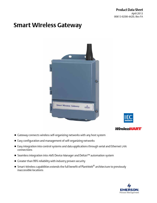
Product Data SheetApril 201300813-0200-4420, Rev FA⏹Gateway connects wireless self-organizing networks with any host system ⏹Easy configuration and management of self-organizing networks⏹Easy integration into control systems and data applications through serial and Ethernet LAN connections⏹Seamless integration into AMS Device Manager and DeltaV™ automation system ⏹Greater than 99% reliability with industry proven security⏹Smart Wireless capabilities extends the full benefit of PlantWeb ® architecture to previously inaccessible locationsSmart Wireless GatewaySmart Wireless Gateway April 2013Emerson Smart Wireless GatewayGain real-time process information with greater than 99% wireless data reliability⏹The Smart Wireless Gateway automatically manages wireless communications in constantly changing environments⏹Native integration with DeltaV and Ovation automation systems provides simple and fast commissioning for wireless field networks⏹Connect to data historians, legacy host systems, and other via a LAN applications through Ethernet, Modbus, Serial, OPC, EtherNet/IP, and HART outputsGuarantee system availability withredundant Smart Wireless Gateways⏹Never lose the wireless network with hot standby capabilityand automatic fault detection⏹Smart Wireless Gateways function as a single system,eliminating the need for duplicate host integration⏹One click configuration and plug-and-play architectureComplete wireless network configuration toolsprovided with each Gateway⏹The integrated web interface allows easy configuration of thewireless network and data integration without the need to installadditional software⏹Complimentary AMS Wireless Configurator software providesEmerson Device Dashboards to configure devices and viewdiagnostic dataDrag and Drop device provisioning enables asecure method to add new wireless devices tothe wireless field networkContentsEmerson’s Smart Wireless Solution .. . . . . . . . . page3IEC 62591 (WirelessHART®)... The Industry Standard page3Ordering Information . . . . . . . . . . . . . . . . . . . . . page4Accessories and Spare parts . . . . . . . . . . . . . . . . page5 Specifications . . . . . . . . . . . . . . . . . . . . . . . . . . . . page6 Product certifications . . . . . . . . . . . . . . . . . . . . . page8 Dimensional drawings . . . . . . . . . . . . . . . . . . . . . page9Smart Wireless Gateway April 2013Emerson’s Smart Wireless SolutionIEC 62591 (Wireless HART®)... The Industry StandardSelf-Organizing, Adaptive Mesh Routing⏹No wireless expertise required, network automatically finds the best communication paths⏹The self-organizing, self-healing network manages multiple communication paths for any given device. If an obstruction is introduced into the network, data will continue to flow because the device already has other established paths. The network will then lay in more communication paths as needed for that device.Reliable Wireless Architecture⏹Standard IEEE 802.15.4 radios⏹2.4 GHz ISM band sliced into 15 radio-channels⏹Time Synchronized Channel Hopping to avoid interference from other radios, WiFi, and EMC sources and increase reliability⏹Direct sequence spread spectrum (DSSS) technology delivers high reliability in challenging radio environment Emerson’s Smart WirelessSeamless Integration via a LAN to All Existing Host Systems ⏹Native integration into DeltaV and Ovation is transparent and seamless⏹Gateways interface with existing host systems via a LAN, using industry standard protocols including OPC, Modbus TCP/IP, Modbus RTU, and EtherNet/IPLayered Security Keeps Your Network Safe⏹Ensures that data transmissions are received only by the Smart Wireless Gateway⏹Network devices implement industry standard Encryption, Authentication, Verification, Anti-Jamming, and Key Management⏹Third party security verification including Achilles andFIPS197- User based login and enforced password strength. Password strength monitoring, user based log in, password reset requirements, automatic lockout, password expiration requirements. Based on guidelines from ISA99.03.03 standard approved level two. SmartPower™ Solutions⏹Optimized Emerson instrumentation, both hardware and software, to extend power module life⏹SmartPower technologies enable predictable power lifeSmart Wireless Gateway April 2013 Ordering InformationTable 1. Smart Wireless Gateway Ordering Information★ The Standard offering represents the most common options. The starred options (★) should be selected for best delivery.The Expanded offering is subject to additional delivery lead time.Model Product Description1420Smart Wireless GatewayPower InputStandard StandardA24 VDC Nominal (10.5-30 VDC)★Ethernet Communications - Physical ConnectionStandard Standard1(1)(2)Ethernet★2(3)(4)Dual Ethernet★Wireless Update Rate, Operating Frequency, and ProtocolStandard StandardA3User Configurable Update Rate, 2.4 GHz DSSS, Wireless HART★Serial Communication]Standard StandardN None★A(5)Modbus RTU via RS485★Ethernet Communication - Data ProtocolsStandard Standard2Webserver, Modbus TCP/IP, AMS Ready, HART-IP★4Webserver, Modbus TCP/IP, AMS Ready, HART-IP, OPC★5(6)DeltaV Ready★6(6)Ovation Ready ★8Webserver, EtherNet/IP, AMS Ready, HART-IP★9Webserver, EtherNet/IP, Modbus TCP/IP, AMS Ready, HART-IP★Options (Include with selected model number)Product CertificationsStandard StandardN5FM Division 2, Non-incendive★N6CSA Division 2, Non-incendive★N1ATEX Type n★ND ATEX Dust★N7IECEx Type n★NF IECEx Dust★KD FM & CSA Division 2, Non-incendive and ATEX Type n★N3China Type n★N4TIIS Type n★Redundancy OptionsStandard Standard RD(7)(8)(9)Gateway Redundancy★AdaptersStandard StandardJ1CM 20 Conduit Adapters★J2PG 13.5 Conduit Adapters★J33/4 NPT Conduit Adapters★Antenna Options(10)Standard Standard WL2Remote Antenna Kit, 50 ft. (15.2 m) cable, Lightning Arrestor★Smart Wireless GatewayApril 2013Accessories and Spare partsWL3Remote Antenna Kit, 20 ft. (6.1 m) and 30 ft. (9.1 m) cables, Lightning Arrestor ★WL4Remote Antenna Kit, 10 ft. (3.0 m) and 40 ft. (12.2 m) cables, Lightning Arrestor ★Expanded WN2(11)High-Gain, Remote Antenna Kit, 25 ft. (7.6m) cable, Lightning ArrestorTypical Model Number:1420A2A3 A 2 N5(1)Single active 10/100 baseT Ethernet port with RJ45 connector.(2)Additional ports disabled.(3)Dual active 10/100 baseT Ethernet ports with RJ45 connectors.(4)Multiple active ports have separate IP addresses, firewall isolation, and no packet forwarding.(5)Convertible to RS232 via adaptor, not included with Gateway.(6)Includes Webserver, Modbus TCP, AMS Ready, HART-IP, and OPC.(7)Requires the selection of Dual Ethernet option code 2.(8)Not available with DeltaV Ready option code 5.(9)Not available with EtherNet/IP option codes 8 and 9(10)The WL2, WL3, WL4, and WN2 options require minor assembly.(11)Not available in all countriesTable 1. Smart Wireless Gateway Ordering Information★ The Standard offering represents the most common options. The starred options (★) should be selected for best delivery.The Expanded offering is subject to additional delivery lead time. Table 2. AccessoriesItem DescriptionPart Number AMS® Wireless SNAP-ON™, 1 Gateway License 01420-1644-0001AMS Wireless SNAP-ON, 5 Gateway Licenses 01420-1644-0002AMS Wireless SNAP-ON, 10 Gateway Licenses 01420-1644-0003AMS Wireless SNAP-ON, 5-10 Upgrade Licenses 01420-1644-0004Serial Port HART Modem and Cables only 03095-5105-0001USB Port HART Modem and Cables only03095-5105-0002Table 3. Spare PartsItem DescriptionPart Number Spare Kit, WL2 Replacement (1), Remote Antenna, 50 ft. (15.2 m) Cable, and Lightning Arrestor01420-1615-0302Spare Kit, WL3 Replacement (1), Remote Antenna, 20/30 ft. (6.1/9.1 m) Cables, and Lightning Arrestor01420-1615-0303Spare Kit, WL4 Replacement (1), Remote Antenna, 10/40 ft. (3.0/12.2 m) Cables, and Lightning Arrestor 01420-1615-0304Spare Kit, WN2 Replacement (1), High Gain, Remote Antenna, 25 ft. (7.6 m) Cable, and Lightning Arrestor (2)01420-1615-0402(1)Can not upgrade from integral to remote antenna.(2)Not available in all countries.Smart Wireless GatewayApril 2013SpecificationsFunctional SpecificationsInput Power10.5 - 30 VDCCurrent DrawRadio Frequency Power Output from AntennaMaximum of 10 mW (10 dBm) EIRPMaximum of 40 mW (16 dBm) EIRP for WN2 High Gain optionEnvironmentalOperating Temperature Range: -40 to 158 °F (-40 to 70 °C)Operating Humidity Range: 10-90% relative humidityEMC PerformanceComplies with EN61326-1:2006.Antenna OptionsIntegrated Omnidirectional AntennaOptional remote mount Omnidirectional AntennaPhysical SpecificationsWeight10 lb (4.54 kg)Material of ConstructionHousingLow-copper aluminum, NEMA 4X PaintPolyurethaneCover GasketSilicone Rubber AntennaIntegrated Antenna: PBT/PC Remote Antenna: Fiber Glass CertificationsClass I Division 2 (U.S.)Equivalent WorldwideCommunication SpecificationsIsolated RS4852-wire communication link for Modbus RTU multidrop connectionsBaud rate: 57600, 38400, 19200, or 9600Protocol: Modbus RTUWiring: Single twisted shielded pair, 18 AWG. Wiring distance up to 4,000 ft. (1,524 m)Ethernet10/100base-TX Ethernet communication portProtocols: EtherNet/IP Modbus TCP, OPC, HART-IP, HTTPS (for Web Interface)Wiring: Cat5E shielded cable. Wiring distance 328 ft. (100 m).ModbusSupports Modbus RTU and Modbus TCP with 32-bit floating point values, integers, and scaled integers.Modbus Registers are user-specified.OPCOPC server supports OPC DA v2, v3EtherNet/IPSupports EtherNet/IP protocol with 32 bit Floating Point values and Integers.EtherNet/IP Assembly Input-Output instances are user configurable.EtherNet/IP specifications are managed and distributed by ODVA.Self-Organizing Network SpecificationsProtocolIEC 62591 (Wireless HART), 2.4 - 2.5 GHz DSSS.Maximum Network Size100 wireless devices @ 8 sec or higher.50 wireless devices @ 4 sec.25 wireless devices @ 2 sec.12 wireless devices @ 1 sec.Supported Device Update Rates1, 2, 4, 8, 16, 32 seconds or 1 - 60 minutesNetwork Size/Latency100 Devices: less than 10 sec.50 Devices: less than 5 sec.Data Reliability>99%C u r r e n t (m A )Operating Current Draw is based on 3.6 Watts average powerconsumption. Momentary startup Current Draw up to twice Operating Current Draw.Smart Wireless Gateway April 2013System Security SpecificationsEthernetSecure Sockets Layer (SSL)- enabled (default) TCP/IPcommunicationsSmart Wireless Gateway AccessRole-based Access Control (RBAC) including Administrator,Maintenance, Operator, and Executive. Administrator hascomplete control of the gateway and connections to hostsystems and the self-organizing network.Self-Organizing NetworkAES-128 Encrypted Wireless HART, including individual sessionkeys. Drag and Drop device provisioning, including unique joinkeys and white listing.Internal FirewallUser Configurable TCP ports for communications protocols,including Enable/Disable and user specified port numbers.Inspects both incoming and outgoing packets.Third Party CertificationWurldtech: Achilles Level 1 certified for network resiliency.National Institute of Standards and Technology (NIST):Advanced Encryption Standard (AES) Algorithm conforming toFederal Information Processing Standard Publication 197(FIPS-197)Smart Wireless Gateway April 2013 Product certificationsApproved Manufacturing LocationsRosemount Inc. – Chanhassen, Minnesota, USAEmerson Process Management GmbH & Co. - Karlstein, GermanyEmerson Process Management Asia Pacific Private Limited - SingaporeBeijing Rosemount Far East Instrument Co., Limited - Beijing, ChinaTelecommunication ComplianceAll wireless devices require certification to ensure that they adhere to regulations regarding the use of the RF spectrum. Nearly every country requires this type of product certification. Emerson is working with governmental agencies around the world to supply fully compliant products and remove the risk of violating country directives or laws governing wireless device usage.FCC and ICThis device complies with Part 15 of the FCC Rules. Operation is subject to the following conditions. This device may not cause harmful interference. This device must accept any interference received, including interference that may cause undesired operation. This device must be installed to ensure a minimum antenna separation distance of 20 cm from all persons. Ordinary Location Certification for FMAs standard, the Gateway has been examined and tested to determine that the design meets basic electrical, mechanical, and fire protection requirements by FM, a nationally recognized testing laboratory (NRTL) as accredited by the Federal Occupational Safety and Health Administration (OSHA).North American CertificationsN5FM Division 2, Non-IncendiveCertificate Number: 3028321Nonincendive for Class I, Division 2, Groups A, B, C, and D.Suitable for Class II, III, Division 1,Groups E, F, and G; Indoors/outdoor locations;Type 4XTemperature Code: T4 (-40 °C < T a < 60 °C)Canadian Standards Association (CSA)N6CSA Division 2, Non-IncendiveCertificate Number: 1849337Suitable for Class I, Division 2, Groups A, B, C, and D.Dust Ignition-proof for Class II, Groups E, F, and G;Suitable for Class III Hazardous Locations.;Install per Rosemount drawing 01420-1011.Temperature Code: T4 (-40 °C < T a < 60 °C)CSA Enclosure Type 4X European Union Directive InformationThe EC declaration of conformity for all applicable European directives for this product can be found on the Rosemount websiteat . A hard copy may be obtained by contacting your local sales representative.European CertificationN1ATEX Type nEx nA nL IIC T4 (-40 °C < T a< 60 °C)Special condition for safe use (X):The surface resistivity of the antenna is greater than onegigaohm. To avoid electrostatic charge build-up, it mustnot be rubbed or cleaned with solvents or a dry cloth.The Apparatus is not capable of withstanding the 500Vinsulation test required by Clause 9.4 of EN 60079-15:2005. This must be taken into account when installing the apparatus.ND ATEX DustCertificate Number: Baseefa 07ATEX0057Ex tD A 22 IP66 T135 (-40 °C < T a < 60 °C)Maximum working Voltage = 28 VN7IECEx Type nCertificate Number: IECEx BAS 07.0012XEx nA nL IIC T4 (-40 °C < T a < 60 °C)Maximum working voltage = 28 VSpecial condition for safe use (X):The surface resistivity of the antenna is greater than onegigaohm. To avoid electrostatic charge build-up, it mustnot be rubbed or cleaned with solvents or a dry cloth.The Apparatus is not capable of withstanding the 500 Vinsulation test required by Clause 9.4 of EN 60079-15:2005. This must be taken into account when installing the apparatus.NF IECEx DustCertification Number: IECEx BAS 07.0013Ex tD A22 IP66 T135 (-40 °C < T a < 60 °C)Maximum working voltage = 28 VCombinations of CertificationsKD Combination of N5, N6, and N1.Smart Wireless Gateway April 2013Dimensional drawingsFigure 1. Smart Wireless Gateway Dimensions are in inches (millimeters)Smart Wireless Gateway April 2013 Remote Antenna KitThe Remote Antenna kit includes sealant tape for remote antenna connection, as well as mounting brackets for the antenna, Lightning Arrestor, and the Smart Wireless Gateway.Lightning protection is included on all the options.*Note that the cables lengths on the remote antenna options WL3 and WL4 are interchangeable for installation convenience.Smart Wireless Gateway April 201311Standard Terms and Conditions of Sale can be found at \terms_of_sale The Emerson logo is a trade mark and service mark of Emerson Electric Co.Rosemount and the Rosemount logotype are registered trademarks of Rosemount Inc.PlantWeb is a registered trademark of one of the Emerson Process Management group of companies.HART and WirelessHART are registered trademarks of the HART Communication Foundation Modbus is a trademark of Modicon, Inc.All other marks are the property of their respective owners.© 2012 Rosemount Inc. All rights reserved.Emerson Process Management Rosemount Inc.8200 Market Boulevard Chanhassen, MN 55317 USA T (U.S.) 1-800-999-9307T (International) (952) 906-8888F (952) Emerson Process Management Blegistrasse 23P.O. Box 1046CH 6341 Baar Switzerland T +41 (0) 41 768 6111F +41 (0) 41 768 Emerson Process Management Asia Pacific Pte Ltd 1 Pandan Crescent Signapore 128461T +65 6777 8211F +65 6777 0947Service Support Hotline: +65 6770 8711Email:***************************.comSmart Wireless Gateway00813-0200-4420, Rev FAProduct Data Sheet April 2013Emerson Process Management Latin America 1300 Concord Terrace, Suite 400Sunrise Florida 33323 USA Tel + 1 954 846 5030。
计算机网络chapter5
5.1.2 Services Provided to the Transport Layer
The network layer services have been designed with the following goals in mind: 1. The services should be independent of the router technology, which means that routing technology is finished only in the network layer. 2. The transport layer does not need to know the number of the routers, type of the routers, and topology of the routers present. 3. The network addresses (the address here is different from the MAC address) should be available to the transport layer, and should use a uniform numbering plan, even across LANs and WANs. Except the above goals, there is still a problem needed to be discussed, it’s about whether the network should provide connectionless service or connection-oriented service, which introduces two kinds of network: Internet and ATM.
计算机网络 Chapter5
host bus (e.g., PCI)
attaches into host’s
system buses combination of hardware, software, firmware
network adapter card
5: DataLink Layer
5-8
Adaptors Communicating
we learned how to do this already (chapter 3)! seldom used on low bit-error link (fiber, some twisted pair) wireless links: high error rates • Q: why both link-level and end-end reliability?
• Error detection not 100% reliable! • protocol may miss some errors, but rarely • larger EDC field yields better detection and correction
otherwise
5: DataLink Layer
But maybe errors nonetheless?
5: DataLink Layer
5-13
Checksumming: Cyclic Redundancy Check
view data bits, D, as a binary number choose r+1 bit pattern (generator), G goal: choose r CRC bits, R, such that
samwontech temi1500 series communication 说明书
TEMI1000 SERIESCOMMUNICATION MANUALTEMPERATURE & HUMIDITYPROGRAMMABLE CONTROLER1. Safety Precautions (1)2. Communication Specifications (3)3. Communication Setting (4)4. Wiring for Communication (5)5. Communication Command (7)6. MODBUS Protocol (18)7. D-REGISTER Description (24)▪ D-REGISTER table (50)2. Communication SpecificationThe TEMI1500 controller provides Half-Duplex method support on RS232C and RS485 communication interface. - RS232C interface supports 1:1 direct communication between host computer on network system and TEMI1500. - RS485 interface supports to connect upper level network system with up to 31 slave TEMI1500 controller.█ Parameters for communication setting■ Factory default value3. Communication settingTEMI1500 provides flexible communication interface RS232C or RS485 from Control Unit directly. ▶In [Figure 1], Using a flat head screw driver to remove the cover.▶In [Figure 2], Communication settings by moving the socket▶It is recommended to use tool like tweezers for setting socket to pin-header correctly.☞Make sure setup completed correctly.[Figure-1] TEMI1500 Display[Figure-2] TEMI1500 Communication Setting COVER4. Wiring for CommunicationConnector wiring between TEMI1500 and network system depends on communication interface setting (RS232C/RS485).█ Modular Connector Pin-Mapping for COM2 port█ Description of Modular Connector Pin-Mapping for COM2 port652 1 RTX+ RTX- RS232C█ 6 Pin connector wiring for RS232C interface█ 6 Pin connector wiring for RS485 interface☞Up to 31 slave TEMI1500 controllers can be connected to a master device by multi-drop networking.☞Make sure to install 200Ω(1/4W) resistor on Last Leg at both end of terminal Slave and Master(PC, PLC).5. Communication Command5.1 The Frame Structure of standard protocolThe frame structure of protocol transmitting upper-level network system to TEMI1500① Protocol HeaderThe beginning of communication command with STX (Start of Text), ASCII string with 0x02.② Slave TEMI1500 AddressSlave unit address of TEMI1500.③ CommandFunction Command for communication. (Refer to 5.2 ~ 5.10).④ DelimiterSymbolize to separate Command and Data by Comma. (',')⑤ DataFormal text strings regulated by communication command rule.⑥ Check Sum-‘SUM' protocol is a more sophisticated one which includes Check Sum as an error check.- Check Sum is calculated as following.1) Add the ASCII code of characters from the character next to STX one by one up to the character prior to SUM2) Represent the lowest one byte of the sum as a hexadecimal notation (2 characters).⑦, ⑧ Protocol TailASCII code to close communication command by indicating CR(0xOD) and LF(0xOA).█ Example for SUM◈ ExampleTo read the consecutively D-Register from D0001 (TEMP.PV) to D0006 (HUMI.SP)- Request : [stx]01RSD,06,0001[cr][lf] - Request (with CheckSum) : [stx]01RSD,06,0001C9[cr][lf]☞ As shown below, hexa decimal value adding each text at 01RSD,06,0001 by ASCII code is 2C9, and lowerdigit 2 characters C9 will be used for CheckSum.█ ASCII Table5.2 Type of Communication CommandTwo types of commands are provided on TEMI1500. One is general READ/WRITE command to read and write information on D-Register, and the other is Reference command to read self-information of TEMI1500.▣ Reference Command▣ READ/WRITE Command☞Each Command can read or write up to 64 D-Register and all of the SED/CLD data will be reset by power OFF, so the data should be registered again.5.3 ERROR ResponseWhen an Error occurs during communication, TEMI1500 transmits a frame as following.▣ Description of Error CodeRSD Command is used to read data in a part of D-Register by consecutive address in sequence.▣ Request Message Frame▣ Response Message Frame▪ Count Number : 1 ~ 64▪ Data : Hexa-decimal 16bit string 4 character with no decimal point◈ExampleTo read the D-Register FROM D0001 (TEMP.PV) TO D0002 (TEMP.SP)- Request : [stx]01RSD,02,0001[cr][lf]- Request (with CheckSum) : [stx]01RSD,02,0001C5[cr][lf]([stx] = 0x02, [cr] = 0x0d, [lf] = 0x0a)Response data will be same as below, when 50.0 of D0001 (TEMP.PV) and 30.0 of D0002 (TEMP.SP)- Response : [stx]01RSD,OK,01F4,012C[cr][lf]- Response (with CheckSum) : [stx]01RSD,OK,01F4,012C19[cr][lf]※Converting procedure 4digits hexadecimal response to decimal value.①Radix conversion (Decimalize) : 01F4(hexadecimal) → 500(decimal)②Multiply factor (decimal point) : 500 * 0.1 → 50.0RRD Command is used to read data in arbitrary single D-Register.▣ Request Message Frame▣ Response Message Frame▪ Count Number : 1 ~ 64▪ Data : Hexa-decimal 16bit string 4 character with no decimal point◈ExampleTo read the D-Register D0001 (TEMP.PV) and D0002 (TEMP.SP)- Request : [stx]01RRD,02,0001,0002[cr][lf]- Request (with CheckSum) : [stx]01RRD,02,0001,0002B2[cr][lf]Response data will be same as below, when 50.0 of D0001 (TEMP.PV) and 30.0 of D0002 (TEMP.SP)- Response : [stx]01RRD,OK,01F4,012C[cr][lf]- Response (with CheckSum) : [stx]01RRD,OK,01F4,012C18[cr][lf]WSD command is used to write data to a part of D-Register by consecutive address in sequence.▣ Request Message Frame▣ Response Message Frame▪ Count Number : 1 ~ 64▪ Data : Hexa-decimal 16bit string 4 character with no decimal point◈ExampleTo write data to the D-Register FROM D0102 (TEMP.SP) TO D0103 (HUMI.SP) on FIX mode operation- Setting TEMP.SP : 50.0 ℃→ Remove decimal point(500) → Hexadecimalize (0x01F4)- Setting HUMI.SP : 80.0 % → Remove decimal point(800) → Hexadecimalize (0x0320)- Request : [stx]01WSD,02,0102,01F4,0320[cr][lf]- Request(with CheckSum) : [stx]01WSD,02,0102,01F4,0320C4[cr][lf]WRD Command is used to write data in arbitrary single D-Register.▣ Request Message Frame▣ Response Message Frame▪ Count Number : 1 ~ 64▪ Data : Hexa-decimal 16bit string 4 character with no decimal point◈ExampleTo write 50.0 ℃ into the D0102(TEMP.SP) and 0.5 ℃ into the D0106(TEMP.SLOPE) on FIX mode operation.- Setting TEMP.SP : 50.0 ℃→ Remove decimal point (500) → Hexadecimalize (0x01F4)- Setting TEMP.SLOPE : 0.5 ℃→ Remove decimal point (5) → Hexadecimalize (0x0005)- Request : [stx]01WRD,02,0102,01F4,0106,0005[cr][lf]- Request(with CheckSum) : [stx]01WRD,02,0102,01F4,0106,0005B6[cr][lf]STD Command is used to list the D-Registers that is necessary to monitor frequently. ▣ Request Message Frame▣ Response Message Frame▪ Count Number : 1 ~ 64◈ExampleTo register D0001(TEMP.PV), D0002(TEMP.SP), D0005(HUMI.PV) and D0006(HUMI.SP)- Request : [stx]01STD,04,0001,0002,0005,0006[cr][lf]- Request(with CheckSum) : [stx]01STD,04,0001,0002,0005,00069A[cr][lf]CLD Command is used to read data in the address which had been registered by STD command. ▣ Request Message Frame▣ Response Message Frame▪ Count Number : 1 ~ 64AMI Command is used to get the controller own-information.▣ Request Message Frame▣ Response Message Frame◈ExmapleTo confirm controller own information- Request : [STX]01AMI[CR][LF]- Response (with CheckSum) : [STX]01AMI38[CR][LF]- Response : [STX]01AMI,OK,TEMI-2000[sp][sp]V00-R00[CR][LF] - Response (with CheckSum) : [stx]01AMI,OK,TEMI-2000[sp][sp]V00-R001D[cr][lf]6. MODBUS Protocol6.1 The Frame Structure of MODBUS protocol ▣ Data Format▣The Frame Structure of MODBUS protocol▶Modbus ASCII▶Modbus RTU▪N : Number of Hexadecimal data6.2 Function CodeTEMI1500 MODBUS protocol provides two function code subsets for READ/WRITE of D-Register and Loop-Back detecting test.Function code-03 is used to read the data of consecutive D-Register block in sequence up to 64 registers.▣ Request Message Frame◈ExmapleRequest message to read the D-Register FROM D0001 (TEMP.PV) TO D0002 (TEMP.SP) should be- MODBUS ASCII :010*********FA[cr][lf]- MODBUS RTU 010*********C40B☞D-Register has to be subtracted ‘1’ from the designated address number on D-Register table in this manual. ▣ Response Message Frame◈ExampleResponse data will be same as below, when 49.3 of D0001 (TEMP.PV) and 10.8 of D0002 (TEMP.SP)- MODBUS ASCII :01030401ED006C9E[cr][lf]- MODBUS RTU 01030401ED006C6BD7Function code-06 is used to write data in arbitrary single D-Register.▣ Request Message Frame◈ExampleRequest message to write ‘2’ to D0100 (pattern number) should be- MODBUS ASCII :01060063000294[cr][lf]- MODBUS RTU 010*********F815☞D-Register has to be subtracted ‘1’ from the designated address number on D-Register table in this manual.▣ Response Message Frame◈ExampleWithout any trouble, response message will be- MODBUS ASCII :01060063000294[cr][lf]- MODBUS RTU 010*********F815Function code-08 is used to test loopback for self-diagnosis.▣ Request Message Frame◈ExampleRequest message to test loopback for self-diagnosis should be- MODBUS ASCII :010*********F5[cr][lf]- MODBUS RTU 01080000000261CA▣ Response Message Frame◈ExampleWithout any trouble, response message will be- MODBUS ASCII :010*********F5[cr][lf]- MODBUS RTU 01080000000261CAFunction code-16 is used to write the data into consecutive D-Register block in sequence up to 64 registers. ▣ Request Message Frame◈ExampleRequest message t o write ‘10.0’ to the D0102(TEMP.SP) and ‘20.0’ to the D0103(HUMI.SP) on FIX mode operation should be- MODBUS ASCII :01100065000204006400C858[cr][lf]- MODBUS RTU 01100065000204006400C875F1▣ Response Message Frame◈ExampleWithout any trouble, response message will be- MODBUS ASCII :01100065000288[cr][lf]- MODBUS RTU 01100065000251D77. D-REGISTER DescriptionD-Register is group of communication data to monitor and control all status of TEMI1500.D-Register is grouped by consecutive 100 addresses based on its concerned function as shown below.☞ D-Register is composed of hexadecimal 4 digit (2-Byte).▪○ : Available to read / write over all designated address range.▪△ : Available to read / write in part of designated address range.▪◈ : Not available to read / write over all designated address range7.1 PROCESS GroupPROCESS group consists of fundamental parameter information concerned with operation process and status. Below table describes the detail Bit Map information of some parameter that indicates its status by Bit.█ Bit Map information of TEMI1500█Bit Map status information D-Register█Common process information D-Register for both PROG / FIX█ PROGRAM operation process information D-Register7.2 FUNCTION GroupFUNCTION group consists of setting parameter D-register related with operational function and process. █Common Operational Function setting D-Register for both PROG / FIX█PROGRAM Operation & Function setting D-Register█FIX Operation & Function setting D-Register█ OPERATION mode & performance setting D-Register☞To activate PROG operation RUN or FIX operation RUN, TEMI1500 should be in individual corresponding STOP(PROG STOP/FIX STOP) state. For example, to activate PROG operation RUN from currently operating FIX RUN state, convert the operation state to PROG STOP (D0104 = 0000, D0101 = 0001[Operation stop trigger]) first, then you can activate PROG operation RUN.RESERVATION group consists of setting and information parameter D-Register related with TIME for Reserve Operation and current time installed in TEMI1500.█ TIME setting and information D-Register█ RESERVE OperationThis setting parameter D-register group is used to establish 9 ON/OFF SIGNALs for temperature and 4 ON/OFF signal for humidity.█ ON/OFF SIGNAL setting D-RegisterThis setting parameter D-register group is used to establish 10 INNER SIGNALs. █ INNER SIGNAL setting D-RegisterThis setting parameter D-register group is used to establish 8 ALARM signals. █ALARM signal setting D-Register█ALARM signal operation condition D-Register7.7 TIME SIGNAL GroupThis setting parameter D-register group is used to establish 16 TIME SIGNALs. █TIME SIGNAL setting D-Register7.8 PID GroupThis setting Group is used for 6 PID subsets for Temperature/Humidity and 3 subsets for Temperature only. █PID setting D-Register7.9 COMMUNICATION GroupThis group is consists of information parameter D-Register concerned communication. █COMMUNICATION concerned information D-RegisterThis INPUT group is used for setting parameter D-Register for sensor and its bias. █INPUT setting D-RegisterThis INPUT group is used for setting parameter D-Register for control output and retransmission.█OUTPUT setting D-Register7.12 DO CONFIG GroupDO CONFIG group consists of setting and information parameter D-Register related to establish RELAY number on I/O board to generate signal and its sub setting for auxiliary Digital Output.█DO CONFIG setting and information D-Register - 1█DO CONFIG setting and information D-Register - 2DI CONFIG group consists of setting parameter D-Register for DI ERROR and its name. █ DI CONFIG setting D-RegisterINITIAL group consists of setting parameter D-Register for system initial configuration. █INITIAL setting D-Register█LED 명칭관련 D-Register7.15 PROGRAM PATTERN Group and Setting7.15.1 PROGRAM GroupPROGRAM group consists of parameter D-Register to arrange program PATTERN organized by each segment profile. Each segment should be established step by step.█ Program PATTERN setting D-Register█ PROGRAM and its REPEAT operation setting D-Register▶ Below describes process step to read programmed PATTERN profile in TEMI1500.▶ Below describes process step to write programming PATTERN profile in TEMI1500.▶ Below describes process step to write program in D1736~D1757.7.15.4 FILE EDIT (PATTERN COPY / DELETE) ▶ Below describes step to copy pattern.▶ Below describes step to delete pattern.7.16 PATTERN INFOPATTERN INFO group consists of programmed pattern and segment information parameter D-Register. █ Programmed pattern and segment information D-Register7.17 FILEFILE group consists of profile information of programmed pattern parameter D-Register.█FILE information D-Register。
无线通信与网络chap3.
service from telephone company
Switching Terms
Switching Nodes:
Intermediate switching device that moves data Not concerned with content of data
Stations:
Priorities can be used
Disadvantages of Packet Switching
Each packet switching node introduces a delay Overall packet delay can vary substantially
Exchanges - switching centers in the network
A switching centers that support subscribers is an end office
Trunks - branches between exchanges
How Packet Switching Works
Higher-speed
High-speed local area network (LAN) Metropolitan area network (MAN) High-speed wide area network (WAN)
Speed and Distance of Communications Networks