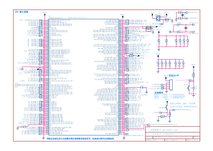
xk-2开发板V5.0原理图(最新)
安富莱STM32-V5开发板_原理图
[2] PF0/FSMC_A0 [2] PF1/FSMC_A1 [2] PF2/FSMC_A2 [2] PF3/FSMC_A3 [2] PF4/FSMC_A4 [2] PF5/FSMC_A5
[11] PF6/LCD_PWM [5,9] PF7/NRF24L01_CSN
[3,5] PF8/SF_CS [8] PF9/ADC3_IN7 [8] PF10/ADC3_IN8
可替换为 STM32F417IGT6/LQFP-176
1 2 3 4 5 6 7 8 9 10 11 12 13 14 15 16 17 18 19 20 21 22 23 24 25 26 27 28 29 30 31 32 33 34 35 36 37 38 39 40 41 42 43 44
PE2/TRACECLK/FSMC_A23/ETH_MII_TXD3 PE3/TRACED0/FSMC_A19 PE4/TRACED1/FSMC_A20/DCMI_D4 PE5/TRACED2/FSMC_A21/TIM9_CH1/DCMI_D6 PE6/TRACED3/FSMC_A22/TIM9_CH2/DCMI_D7 VBAT PI8[RTC_AF2] PC13[RTC_AF1] PC14-OSC32_IN(PC14)[OSC32_IN] PC15-OSC32_OUT(PC15)[OSC32_OUT] PI9/CAN1_RX PI10/ETH_MII_RX_ER PI11/OTG_HS_ULPI_DIR VSS VDD PF0/FSMC_A0/I2C2_SDA PF1/FSMC_A1/I2C2_SCL PF2/FSMC_A2/I2C2_SMBA PF3/FSMC_A3[ADC3_IN9] PF4/FSMC_A4[ADC3_IN14] PF5/FSMC_A5[ADC3_IN15] VSS VDD PF6/TIM10_CH1/FSMC_NIORD[ADC3_IN4] PF7/TIM11_CH1/FSMC_NREG[ADC3_IN5] PF8/TIM13_CH1/FSMC_NIOWR[ADC3_IN6] PF9/TIM14_CH1/FSMC_CD[ADC3_IN7] PF10/FSMC_INTR[ADC3_IN8] PH0-OSC_IN(PH0)[OSC_IN] PH1-OSC_OUT(PH1)[OSC_OUT] NRST PC0/OTG_HS_ULPI_STP[ADC123_IN10] PC1/ETH_MDC[ADC123_IN11] PC2/SPI2_MISO/MII_TXD2/ADC123_IN12/.. PC3/SPI2_MOSI/MII_TX_CLK/ADC123_IN13/.. VDD VSSA VREF+ VDDA PA0-WKUP/UART4_TX/TIM5_CH1/TIM8_ETR/.. PA1/UART4_RX/ETH_MII_RX_CLK/TIM5_CH2/.. PA2/USART2_TX/TIM9_CH1/ETH_MDIO/.. PH2/ETH_MII_CRS PH3/ETH_MII_COL
RPLIDAR S2 开发板用户手册说明书

w w w . slamt ec. comRPLIDAR S2Low Cost 360 Degree Laser Range ScannerDevelopment Kit UserManual Model:S22021-06-11 rev.12CONTENTS (1)OVERVIEW (3)I TEMS IN THE D EVELOPMENT K IT (3)RPLIDAR S2 (4)USB A DAPTER (4)CONNECTION AND USAGE (5)C ONNECTION (5)I NSTALL D RIVER FOR THE USB A DAPTER (5)R UN D EMO A PPLICATION (7)T ROUBLESHOOTING (10)M OTOR S PEED A DJUSTMENT (10)SDK INTRODUCTION AND USAGE (12)RPLIDAR S2P IN D EFINITION AND S PECIFICATION (12)P IN D EFINITION FOR THE USB A DAPTER (13)USB-DC POWER CORD INSTRUCTION (13)C ONFIGURE RPLIDAR S2S CAN F REQUENCY (13)SDK U SAGE (13)OPERATION RECOMMENDATION (15)P RE-H EATING FOR B EST P ERFORMANCE (15)A MBIENT T EMPERATURE (15)A MBIENT L IGHT (15)REVISION HISTORY (16)APPENDIX (17)I MAGE AND T ABLE I NDEX (17)OverviewRPLIDAR S2 development kit includes the matched tools used for evaluatingRPLIDAR ’s performance and initial development. After connecting the RPLIDAR S2 with PC via USB cable and connecting the power adapter to the USB cable,users can observe the cloud map of the environment scanning point collected by the RPLIDAR in RoboStudio and start development based on the SDK.Items in the Development KitRPLIDAR Development Kit contains:o RPLIDAR(PWM motor driver embedded)o USB Adaptero Micro-USB cableo Power cableRPLIDAR S2Power cableUSB adapterMicro-USB cableFigure 1-1 Items in the RPLIDAR Development KitRPLIDAR S2Figure 1-2 The RPLIDAR S2The RPLIDAR S2 development kit contains standard RPLIDAR S2 unit. The RPLIDAR is embedded with logic IO drivable motor controller which can be used to configure the scan frequency by tuning motor speed. Developers can also choose to turn off the motor for power saving purpose.RPLIDAR usage and interface definition will be introduced in the coming sections.USB AdapterThe USB adapter supports a communication rate of 1M baud.Figure 1-3 RPLIDAR AdapterConnectionRPLIDAR S2 can be easily connected to PC according to the following steps.1) Connect RPLIDAR S2 with the USB adapter.Figure 2-1 Connect RPLIDAR S2 and USB Adapter2) Connect the USB adapter to your PC via the Micro-USB cable. If the PC is on, after connecting the USB cable to your PC and connecting the power adapter to the USB cable, the indicator light of the USB will light up but the RPLIDAR will not start scanning.Figure 2-2 Connect the USB Adapter to PC via Micro-USB CableInstall Driver for the USB AdapterThe USB adapter converts UART to USB by using CP2102 chip. You need toinstall the device driver for the chip. The driver can be found in the provided SDK package or downloaded from Silicon Labs ’ official website:/products/mcu/Pages/USBtoUARTBridgeVCPDrivers.aspxConnection and UsageHere’s the installation steps in Windows: after connecting the RPLIDAR with PC, please find the driver file “CP210x VCP Windows” and choose correct operating system version accordingly: x86 for 32-bit OS and x64 for 64-bit OS.Figure 2-3 Choose USB Adapter Driver for InstallationFigure 2-4 Start Page of USB Adapter Driver InstallationAfter Installing the driver according to the above installation steps, you will see corresponding serial port name in the [Control Panel] -> [Device and Printers]. Please refer to the below figure.Figure 2-5 Recognized Serial Port Name Matched with the USB AdapterRun Demo ApplicationSLAMTEC provides a Lidars plugin in RoboStudio for users in test and evaluation. You can view the scan result directly in the UI and save the scan result to files for further processing.This GUI demo can only run under Windows. For Linux and MacOS users, please refer to the other simple demo provided in the SDK.Please make sure you have connected RPLIDAR to PC by using USB adapter and installed the device driver correctly before running the demo application in RoboStudio. Launch RoboStudio and log in.Figure 2-6 RoboStudio Login PageIf the connection is ok, you shall see the user interface is shown as below.1. Click File->Lidars to open the lidar control panel in the left;2. Click Serial Ports to extend the lidar lists and you’ll find the RPLIDAR S2 previously connected to your PC;3. Click the RPLIDAR S2 icon to extend the tool buttons below the icon: the left one is to adjust the motor speed while the right one is to open the tool bar in the major work area as shown in Figure 2-7.Figure 2-7 The Lidar Plugin in RoboStudioThe serial number, version and model of the RPLIDAR S2 will show next with its icon in the lidar control panel. The supported commands of RPLIDAR are showed in the tool bar. The descriptions are listed in the bellow table.ButtonFigure 2-8 The Supported Commands of RPLIDAR in RoboStudioPress the Start Scan button,the scan data will be displayed as below(by default, the motor rotating speed should be about 10Hz.):Figure 2-9 The Scan Outline by RPLIDAR in RoboStudioRight click in the major working area to choose a range so as to zoom in or out the view.The scan frequency is also showed in the above interface. TroubleshootingWhen the scan core or the laser power works abnormally, the scan core will enter protection mode. This state can be retrieved via SDK API. If such scenariohappened, please send restart command to reset the scan core.Motor Speed AdjustmentDuring the running process, different motor rotating speed can be achieved bypressing the button, which can fit in different working environments or meet specific requirements. There will be a speed adjustment dialog box and dash board popped up for users to enter required speed. After entering a value, themotor will work as the settled rotating speed automatically. User can also drag the sliding handle to the required rotating speed.The current actual rotating speed will show in the upper left corner of the major work area. For instance, the actual rotating speed in the following screenshot is 12.88Hz.Figure 2-10 The Motor Speed Adjustment Dialogue of RPLIDAR in RoboStudioRPLIDAR S2 Pin Definition and SpecificationThe RPLIDAR S2 uses separate 5V DC power for powering the range scanner core and the motor system. And the standard RPLIDAR S2 uses XH2.54-5P male socket. Detailed interface definition is shown in the following figure:Figure 3-1 RPLIDAR S2 PinsFigure 3-2 RPLIDAR S2 Pin Definition and SpecificationRPLIDAR S2 uses the one 5V DC power supply for powering the scan motor and the scan core at the same time. No extra power is required.SDK Introduction and UsageColor Signal Name Type Description Min Typical MaxBlackVCCPower Total Power 4.8V 5V 5.5VRed WhiteGNDPower GND 0V 0V 0VYellow Blue RX Input Serial port input of the scanner core0V 3.3V 3.5V GreenTXOutputSerial port output of the scanner core0V3.3V3.5V红XH2.54-5PVCCTXRXGNDMOTOCTLWith build-in and speed-adjustable motor driver, RPLIDAR S2 can control the start, the stop and the rotating speed of the motor via the MOTOCTL signal. o Reference Design for RPLIDAR developmentFigure 3-3 RPLIDAR S2 Pins Reference DesignPin Definition for the USB AdapterThe USB adapter is also using XH2.54-5P specification socket, and it can be connected with RPLIDAR S2 directly. The pin definition is the same as the RPLIDAR S2.USB-DC power cord instructionThe developer kit provides USB-DC power cord for the user to connectadditional power to the USB adapter for additional power supply. For the output voltage and current requirements of the power supply, please refer to the datasheet of the corresponding lidar model.Configure RPLIDAR S2 Scan FrequencyThe RPLIDAR S2’s scan frequency can be modified by invoking the related functions in the SDK to configure the motor speed.Please refer to the RPLIDAR protocol and application note for more information and the SDK for the sample code on RPLIDAR scan frequency.SDK UsageSLAMTEC provides RPLIDAR SDK support on both Windows and Linux platform. And users can embed the SDK source code to other operational system orV5.0 GND TX RXMOTOCTLPower(5V DC)UART PWM GeneratorMCU/DSPRPLIDARembedded system quickly. Please refer to the SDK document for more information.Pre-Heating for Best PerformanceThe scan core will be heating when start working. We recommend pre-heating RPLIDAR (Start the scan mode and the scan motor is rotating) for more than 2 minutes to get the best measurement accuracy.Ambient TemperatureRPLIDAR’s measurement resolution is sensitive to the ambient temperature. Improper use may even damage the sensor. Please avoid using RPLIDAR in extreme high temperature (>50℃) and too low temperature (<-10 ℃).Ambient LightCompared with RPLIDAR A series, RPLIDAR S2 performs better to resist ambient light interference, which supports it to work properly in outdoor environment.Image and Table IndexF IGURE 1-1I TEMS IN THE RPLIDAR D EVELOPMENT K IT (3)F IGURE 1-2T HE RPLIDAR S2 (4)F IGURE 1-3RPLIDAR A DAPTER (4)F IGURE 2-1C ONNECT RPLIDAR S2 AND USB A DAPTER (5)F IGURE 2-2C ONNECT THE USB A DAPTER TO PC VIA M ICRO-USB C ABLE (5)F IGURE 2-3C HOOSE USB A DAPTER D RIVER FOR I NSTALLATION (6)F IGURE 2-4S TART P AGE OF USB A DAPTER D RIVER I NSTALLATION (6)F IGURE 2-5R ECOGNIZED S ERIAL P ORT N AME M ATCHED WITH THE USB A DAPTER (7)F IGURE 2-6R OBO S TUDIO L OGIN P AGE (8)F IGURE 2-7T HE L IDAR P LUGIN IN R OBO S TUDIO (9)F IGURE 2-8T HE S UPPORTED C OMMANDS OF RPLIDAR IN R OBO S TUDIO (9)F IGURE 2-9T HE S CAN O UTLINE BY RPLIDAR IN R OBO S TUDIO (10)F IGURE 2-10T HE M OTOR S PEED A DJUSTMENT D IALOGUE OF RPLIDAR IN R OBO S TUDIO (11)F IGURE 3-1RPLIDAR S2P INS (12)F IGURE 3-2RPLIDAR S2P IN D EFINITION AND S PECIFICATION (12)F IGURE 3-3RPLIDAR S2P INS R EFERENCE D ESIGN (13)。
XK3105E说明书2
一、概述新科XK3105E系列称重仪表是本公司最新研制的新一代高性能称重仪表。
它采用美国Intel公司51系列单片微处理器为测量及控制核心,A/D部分采用带空秤补偿的三积分式A/D 转换器,存贮部件采用最新的E2PROM电改写存贮器,配备智能校准软件,使整个系统无一个可调元件,所有功能全部由键盘实现。
具有操作简便、显示直观、性能可靠等特点。
仪表内配RS232串行通讯接口,可与各类管理微机进行信息交换。
低功耗、交/直流电源设计,使系统可应用于各类便携或常停电的场合。
本仪表可与各类电阻应变式称重传感器相配合,组成各种电子称重系统,广泛应用于工矿企业、商业、码头等需精确计量的场合。
依据应用场合的不同,XK3105E系列仪表目前主要分以下几种:1. 3105E——001:增强型仪表,交流电源供电。
主要用于全电子汽车衡,可接8只700Ω称重传感器,分度数1000~50000可选,供桥电压12V、20mA电流环和RS232串行输出。
机内配可充电蓄电池,停电时可供系统工作16小时。
2. 3105E——002:增强型仪表,交/直流电源供电。
主要用于全电子汽车衡,可接8只700Ω称重传感器,分度数1000~50000可选,供桥电压9V、20mA电流环和RS232串行输出。
3. 3105E——003:通用型仪表,交流电源供电。
主要用于电子平台秤,可接4只350Ω称重传感器,分度数3000或6000,供桥电压12V、20mA电流环串行输出。
可选配RS232接口。
4. 3105E——004:通用型仪表,交/直流电源供电。
主要用于电子平台秤,可接4只350Ω称重传感器,分度数3000或6000,供桥电压9V、20mA电流环串行输出。
可选配RS232接口。
机内配可充电蓄电池,停电时可供系统工作16小时。
5. 3105E——005:台秤用仪表,交流电源供电。
主要用于电子台秤和机电秤改造,可接1只350Ω称重传感器,分度数3000或6000,供桥电压5V,可选配20mA电流环和RS232接口串行。
V2.0TX-51C原理图 郭天祥 8051单片机开发板

USB Title
D
R07 P101
1.5K VDD
P3.0 P3.1
VDD
USB转com
4 3 2 1 4
Size B Date: File: 5
Number 2009-4-18 G:\TX-51C\ok\tx-51c\TX-51C.Sch Sheet of Drawn By: 6
Revision
GND
GND
GND
�
1 2 3 4 5 6 7 8 9 10 11 12 13 14 15 16 17 18 19 20
1 2 3 RS 4 GND 5 LCDEN 6 D0 7 D1 8 D2 9 D3 10 D4 11 D5 12 D6 13 D7 14 15 GND 16
DIOLA DULA WELA D0 D1 D2 D3 D4 D5 D6 D7 SDA CSUSB VCC VLD VCC GND
+
1 3 2
+
20 19 18 17 16 15 14 13 12 11 10 9 8 7 6 5 4 3 2 1
19
P0.0/AD0 P0.1/AD1 P0.2/AD2 P0.3/AD3 P0.4/AD4 P0.5/AD5 P0.6/AD6 P0.7/AD7
C
INT1 LCDEN RS WR RD
P6 1 2 3 4 5 6 7 8 9 10
VCC
DB1 DB2 DB3 DB4 DB5 DB6 DB7 DB8
P7 1 2 3 4 5 6 7 8 9 10 3
GND
VCC
D
P3.1
GND 5 SDA 6 SCL 7 C8 104 C9 104 GND GND I2C 2
项目二5V稳压电源电路原理图的绘制

教案(首页)编号:YJSD/JWC-17-10编制:徐建琴审核:张德芳批准:史岳雷教学过程主要教学内容及步骤学习任务目标1、能力目标:1)会新建和保存项目文件和原理图文件2)能理解项目与文件的关系2、知识目标:1)掌握新建和保存项目文件和原理图文件的操作步骤2)了解“5V稳压电源电路”电路工作原理和电路结构3、情感目标:培养学生学习兴趣,使之利用计算机技能基础,掌握好Protel DXP工程和文件的新建、保存、打开的操作。
教学指导教师引导示范,让学生熟悉操作方法;通过对项目电路的剖析,让学生初步了解“5V稳压电源电路”,为后续项目的实施打下基础。
学习活动任务一新建项目文件,创建电路原理图文件操作步骤:步骤一启动 Protel DXP 2004方法1:双击Windows桌面的快捷方式图标。
方法2:单击【开始】菜单→【所有程序】→【Altium】→【DXP 2004】。
步骤二新建PCB项目文件方法1:选择菜单命令【文件】→【创建】→【项目】→【PCB项目】。
方法2:单击主界面左下角【Project】标签,调出【Project】面板,单击【项目】按钮→在弹出的快捷菜单中选择【追加新项目】→【PCB 项目】。
步骤三保存PCB项目文件建立PCB项目文件后,一般要将项目文件保存为自己需要的文件名,并保存到指定的文件夹中。
方法1:选择菜单命令【文件】→【保存项目】或【另存项目为】方法2:在【Project】面板的默认项目名称“PCB_Project1.PRJPCB”上单击鼠标右键,在弹出的快捷菜单中选择【保存项目】或【另存项目为】。
步骤四新建原理图文件学习活动方法2:在【Project】面板的项目名称“5V稳压电源.PRJPCB”上单击鼠标右键,在弹出的快捷菜单中选择【追加新文件到项目中】→【Schematic】。
步骤五保存原理图文件建立原理图文件后,一般要将原理图文件保存为自己需要的文件名,并保存到与项目文件一致的文件夹中。
51单片机最小系统原理图

51单片机最小系统原理图接触过单片机的朋友们都时常会听到别人提"最小系统"这个词.那到底什么是最小系统,有怎样设计称上"最小"呢?下面让依依电子来告诉大家:单片机最小系统,或者称为最小应用系统,是指用最少的元件组成的单片机可以工作的系统.对51系列单片机来说,单片机+晶振电路+复位电路,便组成了一个最小系统.但是一般我们在设计中总是喜欢把按键输入、显示输出等加到上述电路中,成为小系统。
应用89C51(52)单片机设计并制作一个单片机最小系统,达到如下基本要求:1、具有上电复位和手动复位功能。
2、使用单片机片内程序存储器。
3、具有基本的人机交互接口。
按键输入、LED 显示功能。
4、具有一定的可扩展性,单片机I/O口可方便地与其他电路板连接。
51单片机学习想学单片机,有一段时间了,自己基础不好,在网上提了许多弱智的问题,有一些问题网友回答了,还有一些为题许多人不屑一顾。
学来学去,一年多过去了,可是还是没有入门,现在我就把我学习中遇到的一些问题和大家分享一下,希望在大虾的帮助下能快速的入门:)在学习之前我在网上打听了一下atmel公司的单片机用的人比较多,avr系列这几年在国内比较流行,但是考虑到avr还是没有51系列用的人多,51系列的许多技术在实践中都已经的到了前人的解决,遇到问题后,有许多高人可以帮助解决,所以这次学习,选用了atmel公司的at89s52,来进行学习。
学习单片机是需要花费时间实践的;学之前我们先准备好所需的东西一、所需硬件at89s52一片;8m晶振一个,30pf 的瓷片电容两个;10uf电解电容一个,10k的电阻一个;万用板(多孔板)一块;其他的器件如电烙铁一把30w的,松香,焊锡若干,如果是第一次学习,不知道这些东西,没关系,以下是它们的照片:Atmel公司生产的at89s52 8m晶振22pf瓷片电容电解电容图1/4 w 10k 的电阻普通的电木万用板好了,有了这些东西,我们就可以把它们组合到一起做成我们的最小系统了:)有了这些东西我们怎么焊接丫?不用着急,过一会我们把原理图给大家画出来大家就会了。
XK3102A说明书2
3 操作说明 ..........................................................8 3.1 按键说明.....................................................8 3.2 功能项说明...................................................8 3.3 重量标定 FN1 .................................................9 3.4 工作参数设置 FN2 ............................................12 3.5 通讯参数设置 FN3 ............................................15 3.6 模拟输出设置 FN4 ............................................16 3.7 继电器输出设置 FN5 ..........................................18 3.8 调整模拟输出的底端与顶端 FN6 ................................19 3.9 部分参数快速查看............................................21 3.10 开机自检信息...............................................22 3.11 错误信息提示...............................................22
扬州新能电动执行机构智能型说明书(触屏式).
XKZ W/B-XT 智能型电动执行机构说明书扬州新能电力设备有限公司扬州中德电力设备制造厂注意事项感谢贵单位使用本公司产品,请在使用前务必详细阅读本说明书,否则可能造成失效,损坏机构、烧毁电机等严重后果,切记以下注意事项:1、安装前应将电动执行机构存放在清洁干燥的室内,若放在室外,应离地面一定高度,并应有防雨防潮措施。
2、吊装时不得使接线部件受力。
3、电缆和导线进入后,必须确保电气箱盖和电缆进口处密封良好,否则潮气和雨水将进入电气箱内,造成零件锈蚀和电气控制失效。
4、手动操作前应将手电动切换手柄按箭头方向推(或拉),若推不下去时需边推边转手轮,切换到位即可手动操作。
手轮旋向与输出轴旋向一致,通常顺时针为关阀,逆时针为开阀。
电动时切换手柄将自动复位,切不可手动强行扳回,否则将损坏机构。
5、一般不得在阴雨天于户外打开电气箱盖、电机等密封部位,打开电气箱盖时,必须切断电源。
6、拆卸重装(包括电气箱盖打开后重装)时,应注意检查密封件,发现损伤应及时更换,密封部位必须盖严并用螺钉紧固到位。
7、对于不经常使用的阀门,应定期检查保养运行操作,建议每月运行一次,时间不超过十分钟。
目录一、概述..................................................................... 1 二、型号表示方法与防爆标志.......................................... 1 三、主要技术性能参数................................................... 2 四、外型及安装尺寸...................................................... 3 五、主要结构及传动原理................................................ 4 六、电气控制部分......................................................... 6 七、遥控器设定方法...................................................... 16 八、检修备品............................................................... 16 九、订货须知 (16)一、概述本系列阀门电动执行机构把电气控制部分与机械减速机构组合为一体,采用智能式设计,形成智能式一体化电动执行机构。
安富莱_STM32-V5开发板_原理图(D030-8)
C87 104/50
C88 104/50
C90 104/50
Hale Waihona Puke C89 104/50C92 104/50
C91 104/50
C94 104/50
[11] PF6/LCD_PWM PF7/NRF24L01_CSN [3,5] PF8/SF_CS [8] PF9/ADC3_IN7 [8] PF10/ADC3_IN8 [1] PH0-OSC_IN [1] PH1-OSC_OUT [1,2,6,7,9,11] NRST [8] PC0/ADC123_IN10 [7] PC1/ETH_MDC [5,9] PC2/NRF905_CSN/VS1053_XCS [6] PC3/I2S2_SD [5,9] [10] CPU_VREF CPU_VDDA PA0/ADC123_IN0 [8] [7] PA1/ETH_RMII_REF_CLK PA2/USART2_TX/ETH_MDIO [5] PH2/JOY_U [5] PH3/JOY_D
U12 STM32F407IGT6/LQFP-176 [2,3,9] PE2/FSMC_A23/SD_DETECT [2] PE3/FSMC_A19 [2] PE4/FSMC_A20 [2] PE5/FSMC_A21 [2] PE6/FSMC_A22 [1] VBAT [5] PI8/KEY1 [5] PC13/KEY2 [1] PC14-OSC32_IN [1] PC15-OSC32_OUT [4] PI9/CAN1_RX [5,11] PI10/TP_NCS [5] PI11/KEY3 [2] [2] [2] [2] [2] [2] PF0/FSMC_A0 PF1/FSMC_A1 PF2/FSMC_A2 PF3/FSMC_A3 PF4/FSMC_A4 PF5/FSMC_A5 1 2 3 4 5 6 7 8 9 10 11 12 13 14 15 16 17 18 19 20 21 22 23 24 25 26 27 28 29 30 31 32 33 34 35 36 37 38 39 40 41 42 43 44 45 46 47 48 49 50 51 52 53 54 55 56 57 58 59 60 61 62 63 64 65 66 67 68 69 70 71 72 73 74 75 76 77 78 79 80 81 82 83 84 85 86 87 88
医学影像设备学第五章X线机主机单元电路2
200
VR2
R2 9K C1-02
C8 C1-01
VR1
10K
R4-01 k2 - U R5
1K
1M
R3
C3
D2-2 2
-
D2-1
M1
+ 3
10K 20K
6 R6-01 2
-
10K
6
M2-02
+ 3
R4-02 1K
C2 C7
C4-02
R1
k2 - U
VR3
50
R6-02
R6-03
+ F-mA
10K
10K
ic
ic ic
ic
M B
N
C
ic
D1 D4
D2 R
D3
+ mA
-
ic ic
i c ic
ic
阴极高压电缆
XX图9 5-34 变压器式电容电流补偿电路
B
R
JC 1
D5 D1
250
10 D 2 JC 3
mA 0
G8
D4
D3
二、三相全波整流高压次级电路
三相与单相全波桥式 整流电路比较有以下 优点 :
1.脉动率很小
A5→RD2→R2 →JC1(常开)
→DZ1-
7→B2→DZ18→JC1(常开) →B1-11。
(2)摄影高压初 级电路:B1-
A4→RD1→→
DZ1-
7→B2→DZ18→JC3(常开) →B1-12。
- 10 0 V
-B 1 A 4
0V
-B 1 A 5
-B 1 A 7
B 1 150V