EIA-364-23A(接触电阻)
MOLEX汽车连接器产品大全-4
71349-X055
71349-X089
71349-X022
71349-X056
71349-X090
71349-X023
71349-X057
71349-X091
71349-X024
71349-X058
71349-X092
71349-X025
71349-X059
71349-X093
71349-X026
/product/cgrid/cgrid.html
D-31
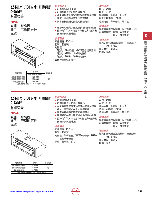
2.54 (.100英寸) 引脚间距 C-Grid® 有罩接头
71349 双排,表面贴装 立式,配有或未配有固定栓
D
特点和优点 • 全防护塑壳,可在插拔时保护引脚 • 极化防误插槽在连接器插接时可引导导
向轨,以防止引脚被碰坏。 • 闩窗在插接后提供强制锁定 • 推压式固定栓在焊脚焊接时提供对印刷
参考信息 产品规格:PS-75100-001 包装:托盘包装 UL档案编号:E29179 CSA档案编号:LR19980 对配端:71973,带凸缘 设计计量单位:英寸
镀金:50次插拔
物理参数 塑壳:黑色耐高温热塑料,阻燃级别
为UL 94V-0级 端子材料:铜合金 电镀:见表
电镀方式
订购号
是否无铅
最薄15微英寸选择性镀金
15-47-76XX
最薄30微英寸选择性镀金
15-47-77XX
是
150微英寸镀锡/铅
15-47-75XX
用电路数量替换XX。 06-72 (仅为偶数)
镀金:50次插拔
D
设计计量单位:英寸
物理参数 塑壳:黑色聚酯,阻燃级别为UL 94V-0级
端子材料:铜合金
美国插标准
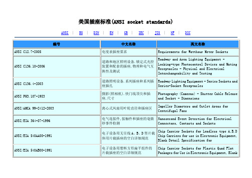
电连接器和插座的电容试验程序
Capacitance Test Procedure for Electrical Connectors and Sockets
ANSI/EIA-364-52A-2003
连接器/插座中使用的触点终端的软钎焊性的TP52试验程序
TP 52 Test Procedures for Solderability of Contact Terminations Use in Connectors/Sockets
ANSI/EIA-540A000-A-1990
ANSI/EIA 540AA00-1991
电子设备用无引线A、B、D型片载体用片载插座的空白详细规范
Chip Carrier Sockets for Leadless type A,B,D Chip Carriers for use in Electronic Equipment, Blank Detail Specification for
Combustion Characteristics Test Procedure for Electrical Connector Housing, Connector Assemblies and Sockets
ANSI/EIA-364-82A-2005
电连接器套、连接器组件和插座的塑料腐蚀性试验程序
Roadway and Area Lighting Equipment - Locking-type Photocontrol Devices and Mating Receptacles - Physical and Electrical Interchangeability and Testing
EIA-364-1000_01A
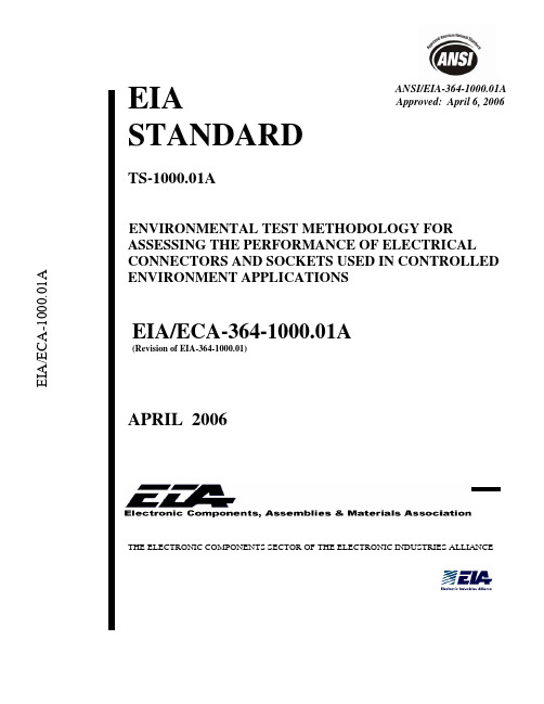
ANSI/EIA-364-1000.01AEIASTANDARDTS-1000.01AE NVIRONMENTAL TEST METHODOLOGY FOR ASSESSING THE PERFORMANCE OF ELECTRICAL CONNECTORS AND SOCKETS USED IN CONTROLLED ENVIRONMENT APPLICATIONSEIA/ECA-364-1000.01A(Revision of EIA-364-1000.01)APRIL 2006THE ELECTRONIC COMPONENTS SECTOR OF THE ELECTRONIC INDUSTRIES ALLIANCENOTICEEIA Engineering Standards and Publications are designed to serve the public interest through eliminating misunderstandings between manufacturers and purchasers, facilitating interchangeability and improvement of products, and assisting the purchaser in selecting and obtaining with minimum delay the proper product for his particular need. Existence of such Standards and Publications shall not in any respect preclude any member or nonmember of EIA from manufacturing or selling products not conforming to such Standards and Publications, nor shall the existence of such Standards and Publications preclude their voluntary use by those other than EIA members, whether the standard is to be used either domestically or internationally.Standards and Publications are adopted by EIA in accordance with the American National Standards Institute (ANSI) patent policy. By such action, EIA does not assume any liability to any patent owner, nor does it assume any obligation whatever to parties adopting the Standard or Publication.This EIA Standard is considered to have International Standardization implication, but the International Electrotechnical Commission activity has not progressed to the point where a valid comparison between the EIA Standard and the IEC document can be made.This Standard does not purport to address all safety problems associated with its use or all applicable regulatory requirements. It is the responsibility of the user of this Standard to establish appropriate safety and health practices and to determine the applicability of regulatory limitations before its use.(From Standards Proposal No. 5038 formulated under the cognizance of the CE-2.0 National Connector Standards Committee.Published by©ELECTRONIC INDUSTRIES ALLIANCE 2006Technology Strategy & Standards Department2500 Wilson BoulevardArlington, VA 22201PRICE: Please refer to the currentCatalog of EIA Electronic Industries Alliance Standards andEngineering Publicationsor call Global Engineering Documents, USA and Canada (1-800-854-7179)International (303-397-7956)All rights reservedPrinted in U.S.A.中国可靠性网 PLEASE !DON'T VIOLATETHELAW!This document is copyrighted by the EIA and may not be reproduced without permission.Organizations may obtain permission to reproduce a limited number of copies through entering into a license agreement. For information, contact:Global Engineering Documents15 Inverness Way EastEnglewood, CO 80112-5704 or callUSA and Canada (1-800-854-7179), International (303-397-7956)iCONTENTSClause Page (1)1 Introduction (1)1.1 Scope2 Test specimen (1) (1)2.1 Condition2.2 Sample (2)size (2)3 Testgroups4 Details to be specified (11) (11)documentation5 TestTable1 Test Group 1 (required for all connectors or sockets) (3)2 Test Group 2 (required for all connectors and sockets) (4)3 Test Group 3 (required for all connectors or sockets) (5)4 Test Group 4 (required for connectors or sockets with a precious metal platingon the contacts) (6)5 Test Group 5 (required for connectors or sockets with a tin-based platingon the contacts and optional for connectors or sockets with < 0.38 micronsof gold plating on the contacts) (8)6 Test Group 6 (required for connectors or sockets with a surface treatmenton the contacts or for connectors or sockets with a wipe length of0.127 mm or less) (9)7 Test Group 7 (required for connectors or sockets rated for> 50 mating/unmating cycles) (10)8 Test durations (hours) for temperature life (13)9 Test durations (hours) for temperature life (preconditioning) (14)ii中国可靠性网 CONTENTS (continued)Annex Page................................................................................................................. A-1 A Normative................................................................................................................ B-1 B Informativeiii中国可靠性网 EIA-364-1000.01APage 1TEST SEQUENCE No. 1000.01AENVIRONMENTAL TEST METHODOLOGY FOR ASSESSINGTHE PERFORMANCE OF ELECTRICAL CONNECTORS AND SOCKETSUSED IN CONTROLLED ENVIRONMENT APPLICATIONS(From EIA Standards Proposal No. 5038, formulated under the cognizance of EIA CE-2.0 Committee on National Connector Standards, and previously published in EIA-364-1000.01.)1 Introduction1.1 ScopeThis standard establishes the test procedures and test sequences to be followed when evaluating the performance of electrical connectors and sockets used in controlled environments. 1) Furthermore, it applies to contacts operating under low level circuit conditions. 2)The assumption is made that the contacts are metal. Polymer contacts, or other contact types, may require a different test methodology.2 Test specimen2.1 ConditionConnectors or sockets to be tested may be prototype parts to assess their design, or production parts to evaluate against an end user’s criteria. In either case, preparation of them for testing should consider board carrier or cable assembly processes. When access to a production or prototype soldering process to attach test specimens to a board carrier is not available, chemical and temperature exposure may be simulated by the procedures of EIA-364-11 (Resistance to Solvents Test Procedure for Electrical Connectors); and EIA-364-56, procedure 3 test condition E for a wave solder process, procedure 4 for a vapor phase reflow process, or procedure 5 level #3 for an infrared reflow process (Resistance to Soldering Heat Test Procedure for Electrical Connectors). When pressing test specimens to a board carrier or when terminating test specimens to a cable, appropriate tools should be used.1) Controlled environments are classified as no more severe than class number G1.2, according to the latest revision of EIA-364 (Electrical Connector/Socket Test Procedures Including Environmental Classifications).2) The applied voltage, generally < 50 millivolts, is not sufficient to break through any surface film. For contacts not operating under low level circuit conditions, such as those used in power applications; see the latest revision of EIA-364-70 (Test Procedure for Current vs. Temperature Rise of Electrical Connectors).EIA-364-1000.01APage 2NOTE ⎯Board carrier assembly operations are typically setup to attach all solderable components before press-fit connectors. Even so, the connectors may still besubjected to manual or automated soldering conditions during componentrework. This circumstance should be considered by the test engineer whenpreparing test specimens.2.2 Sample size2.2.1 For the test sequences in each of the test groups of clause 3, at least 100 separable contact interfaces from at least 5 connector or socket systems (plug/receptacle) should be evaluated. For low contact counts, at least 10 connector or socket systems should be tested. If Option #1A and Option #1B of test group 4 are chosen, then twice this sample size for that test sequence is required. If the connector or socket contains contacts that differ in the design of the critical area, then the sample size requirement should be applied to each design and the test results should be distinguishable.2.2.2 When a failure rate is desired, a significantly larger sample size for the test sequence in test group 4 should be tested. The user may require a larger sample size for other test groups, as well. The increase is dictated by the method of calculation chosen by the user.3 Test groupsFor an understanding of the objective of each test contained in the test groups; see annex B.中国可靠性网 EIA-364-1000.01APage 3 Table 1 - Test Group 1 (required for all connectors or sockets)Test Order Test Test procedure Condition oftest specimensTest criteria1 Low level contactresistance EIA-364-23 (termination ofconnector or socket to board carrieror cable shall be included inmeasurements)Mated None(base line measurements)2 Durability(preconditioning) EIA-364-09 (perform 5 unplug/plugcycles if the application requires upto 25 over the life of the connectoror socket; 20 cycles if theapplication requires 26-200; or, 50cycles if the application requires201 or greater)No evidence of physicaldamage3 Temperature life EIA-364-17, method A (see table 8for durations and temperatures)Mated None4 Low level contactresistance EIA-364-23 (termination ofconnector or socket to board carrieror cable shall be included inmeasurements)Mated Change in measurementsevaluated against criteriaspecified by user5 Reseating Manually unplug/plug the connectoror socket. Perform 3 such cycles. No evidence of physical damage6 Low level contactresistance EIA-364-23 (termination ofconnector or socket to board carrieror cable shall be included inmeasurements)Mated Change in measurementsevaluated against criteriaspecified by userEIA-364-1000.01APage 4Table 2 - Test Group 2 (required for all connectors and sockets)Test Order Test Test procedure Condition oftest specimensTest criteria1 Low level contactresistance EIA-364-23 (termination ofconnector or socket to board carrieror cable shall be included inmeasurements)Mated None(base line measurements)2 Durability(preconditioning) EIA-364-09 (perform 5 unplug/plugcycles if the application requires upto 25 over the life of the connectoror socket; 20 cycles if theapplication requires 26-200; or, 50cycles if the application requires201 or greater)No evidence of physicaldamage3 Thermal shock EIA-364-32, test condition I(10 cycles with the exception ofexposure times. Place athermocouple in the center of thelargest mass component of theconnector or socket that is in thecenter of the test chamber to insurethat the contacts reach thetemperature extremes beforeramping to the other temperature. )Mated None4 Low level contactresistance EIA-364-23 (termination ofconnector or socket to board carrieror cable shall be included inmeasurements)Mated Change in measurementsevaluated against criteriaspecified by user5 Cyclic temperature &humidity EIA-364-31 (Cycle the connector orsocket between 25 °C ± 3 °C at80 % ± 3% RH and 65 °C ± 3 °C at50 % ± 3% RH. Ramp times shouldbe 0.5 hour and dwell times shouldbe 1.0 hour. Dwell times start whenthe temperature and humidity havestabilized within the specifiedlevels. Perform 24 such cycles.)Mated None6 Low level contactresistance EIA-364-23 (termination ofconnector or socket to board carrieror cable shall be included inmeasurements)Mated Change in measurementsevaluated against criteriaspecified by user7 Reseating Manually unplug/plug the connectoror socket. Perform 3 such cycles. No evidence of physical damage8 Low level contactresistance EIA-364-23 (termination ofconnector or socket to board carrieror cable shall be included inmeasurements)Mated Change in measurementsevaluated against criteriaspecified by user中国可靠性网 Test Order Test Test procedure Condition oftest specimensTest criteria1 Low level contactresistance EIA-364-23 (termination ofconnector or socket to board carrieror cable shall be included inmeasurements)Mated None(base line measurements)2 Durability(preconditioning) EIA-364-09 (perform 5 unplug/plugcycles if the application requires upto 25 over the life of the connectoror socket; 20 cycles if theapplication requires 26-200; or, 50cycles if the application requires201 or greater)No evidence of physicaldamage3 Temperaturelife(preconditioning) EIA-364-17, method A (see table 9for durations and temperatures)Mated None4 Low level contactresistance EIA-364-23 (termination ofconnector or socket to board carrieror cable shall be included inmeasurements)Mated Change in measurementsevaluated against criteriaspecified by user5 Vibration EIA-364-28, test condition VII, testcondition letter D (15 minutes ineach of 3 mutually perpendiculardirections. Both mating halvesshould be rigidly fixed so as not tocontribute to the relative motion ofone contact against another. Themethod of fixturing should bedetailed in the test report.) Mated No evidence of physicaldamage6 Low level contactresistance EIA-364-23 (termination ofconnector or socket to board carrieror cable shall be included inmeasurements)Mated Change in measurementsevaluated against criteriaspecified by usera precious metal plating on the contacts)Test Order Test Test procedure Condition oftest specimensTest criteria1 Low level contactresistance EIA-364-23 (termination ofconnector or socket to board carrieror cable shall be included inmeasurements)Mated None(base line measurements)2 Durability(preconditioning) EIA-364-09 (perform 5 unplug/plugcycles if the application requires upto 25 over the life of the connectoror socket; 20 cycles if theapplication requires 26-200; or, 50cycles if the application requires201 or greater)No evidence of physicaldamage3 Temperaturelife(preconditioning) EIA-364-17, method A (see table 9for durations and temperatures)Mated None4 Low level contactresistance EIA-364-23 (termination ofconnector or socket to board carrieror cable shall be included inmeasurements)Mated Change in measurementsevaluated against criteriaspecified by user5 Mixed flowing gas EIA-364-65, class IIA (5 days tosimulate a 3-year field life; 7 days tosimulate a 5-year field life; or 14days to simulate a 10-year field life)See note None6 Low level contactresistance EIA-364-23 (termination ofconnector or socket to board carrieror cable shall be included inmeasurements)Mated Change in measurementsevaluated against criteriaspecified by user7 Thermal disturbance Cycle the connector or socketbetween 15 °C ± 3 °C and 85 °C ±3 °C, as measured on the part.Ramps should be a minimum of 2°C per minute, and dwell timesshould insure that the contacts reachthe temperature extremes (aminimum of 5 minutes). Humidityis not controlled. Perform 10 suchcycles.Mated None8 Low level contactresistance EIA-364-23 (termination ofconnector or socket to board carrieror cable shall be included inmeasurements)Mated Change in measurementsevaluated against criteriaspecified by usera precious metal plating on the contacts) (continued)Test Order Test Test procedure Condition oftest specimensTest criteria9 Reseating Manually unplug/plug the connectoror socket. Perform 3 such cycles. No evidence of physical damage10 Low level contactresistance EIA-364-23 (termination ofconnector or socket to board carrieror cable shall be included inmeasurements)Mated Change in measurementsevaluated against criteriaspecified by userNOTE ⎯ For 1-piece connectors or sockets: 1) expose unmated for 2/3 of the test duration; 2) mate each connector or socket to the same part that it was mated to during temperature life (preconditioning); and 3) expose for the remainder of the test duration. For 2-piece connectors, select either Options #1A and #1B or select Option #2.⎯Option #1A (plugs): 1) expose 1/2 of the specimens unmated for 2/3 of the test duration; 2) mate each specimen to the same receptacle that it was mated to during temperature life (preconditioning); and, 3) expose for the remainder of the test duration.⎯Option #1B (receptacles): 1) expose 1/2 of the specimens unmated for 2/3 of the test duration; 2) mate each specimen to the same plug that it was mated to during temperature life (preconditioning); and, 3) expose for the remainder of the test duration.⎯Option #2: 1) expose all plugs and receptacles unmated for 2/3 of the test duration; 2) mate each piece to the same piece that it was mated to during temperature life (preconditioning); and, 3) expose for the remainder of the test duration.Table 5 - Test Group 5 (required for connectors or sockets with a tin-based plating on the contacts and optional for connectors or sockets with< 0.38 microns of gold plating on the contacts)Test Order Test Test procedure Condition oftest specimensTest criteria1 Low level contactresistance EIA-364-23 (termination ofconnector or socket to board carrieror cable shall be included inmeasurements)Mated None(base line measurements)2 Durability(preconditioning) EIA-364-09 (perform 5 unplug/plugcycles if the application requires upto 25 over the life of the connectoror socket; 20 cycles if theapplication requires 26-200; or, 50cycles if the application requires201 or greater)No evidence of physicaldamage3 Temperaturelife(preconditioning) EIA-364-17, method A (see table 9for durations and temperatures)Mated None4 Low level contactresistance EIA-364-23 (termination ofconnector or socket to board carrieror cable shall be included inmeasurements)Mated Change in measurementsevaluated against criteriaspecified by user5 Thermal cycling Cycle the connector or socketbetween 15 °C ± 3°C. and 85 °C ±3 °C, as measured on the part.Ramps should be a minimum of2 °C per minute, and dwell timesshould insure that the contacts reachthe temperature extremes (aminimum of 5 minutes). Humidityis not controlled. Perform 500 suchcycles.Mated None6 Low level contactresistance EIA-364-23 (termination ofconnector or socket to board carrieror cable shall be included inmeasurements)Mated Change in measurementsevaluated against criteriaspecified by user7 Reseating Manually unplug/plug the connectoror socket. Perform 3 such cycles. No evidence of physical damage8 Low level contactresistance EIA-364-23 (termination ofconnector or socket to board carrieror cable shall be included inmeasurements)Mated Change in measurementsevaluated against criteriaspecified by userTable 6 - Test Group 6 (required for connectors or sockets with a surface treatment on the contacts or for connectors or sockets with a wipe length of 0.127 mm or less)Test Order Test Test procedure Condition oftest specimensTest criteria1 Low level contactresistance EIA-364-23 (termination ofconnector or socket to board carrieror cable shall be included inmeasurements)Mated None(base line measurements)2 Durability(preconditioning) EIA-364-09 (perform 5 unplug/plugcycles if the application requires upto 25 over the life of the connectoror socket; 20 cycles if theapplication requires 26-200; or, 50cycles if the application requires201 or greater)No evidence of physicaldamage3 Dust EIA-364-91 (benign dustcomposition)Unmated None4 Low level contactresistance EIA-364-23 (termination ofconnector or socket to board carrieror cable shall be included inmeasurements)Mated Change in measurementsevaluated against criteriaspecified by user (see note)5 Thermal disturbance Cycle the connector or socketbetween 15 °C ± 3 °C and 85 °C ±3 °C , as measured on the part.Ramps should be a minimum of20C./minute, and dwell times shouldinsure that the contacts reach thetemperature extremes (a minimumof 5 minutes). Humidity is notcontrolled. Perform 10 such cycles.Mated None6 Low level contactresistance EIA-364-23 (termination ofconnector or socket to board carrieror cable shall be included inmeasurements)Mated Change in measurementsevaluated against criteriaspecified by user (see note)7 Reseating Manually unplug/plug the connectoror socket. Perform 3 such cycles. No evidence of physical damage8 Low level contactresistance EIA-364-23 (termination ofconnector or socket to board carrieror cable shall be included inmeasurements)Mated Change in measurementsevaluated against criteriaspecified by user (see note)NOTE ⎯ Failure to meet the criteria does not necessarily disqualify the connector or socket. Rather, it may indicate the need for protection against particulate contamination, such as that afforded by a dust cover. For a connector or socket with a surface treatment on the contacts, a comparison of the test results to those obtained for the same connector or socket without a surface treatment on the contacts should be made. Only then can the impact of the surface treatment be determined.Table 7 - Test Group 7 (required for connectors or sockets rated for> 50 mating/unmating cycles)Test Order Test Test procedure Condition of test specimensTest criteria 1 Dielectric withstanding voltage EIA-364-20 (voltage level, ac or dc,and the orientation of the connectoror socket should be defined in thedetails of the test report)Mated No disruptive discharge No leakage current in excess of the maximum specified by user 2 Low level contact resistance EIA-364-23 (Termination of theconnector or socket to the boardcarrier or cable shall be included in the measurements. The orientation of the connector or socket should be defined in the details of the test report.)Mated None (base line measurements) 3 Durability EIA-364-09 (Perform the ratednumber of unplug/plug cycles.Retention features, such as latches, should not be deactivated. The orientation of the connector or socket should be defined in the details of the test report.)No evidence of physical damage 4 Low level contact resistance EIA-364-23 (Termination of theconnector or socket to the boardcarrier or cable shall be included inthe measurements. The orientation of the connector or socket should be defined in the details of the test report.)Mated Change in measurements evaluated against criteria specified by user 5 Dielectric withstanding voltage EIA-364-20 (voltage level, ac or dc,and the orientation of the connectoror socket should be defined in thedetails of the test report)Mated No disruptive discharge No leakage current in excess of the maximum specified by user NOTES1 Separate sets of test specimens may be used to assess dielectric withstanding voltage and the change in low level contactresistance.2 Dielectric withstanding voltage testing should involve different contacts than low level contact resistance testing.4 Details to be specifiedThe following details shall be specified in the referencing document:4.1 Rated number of durability cycles4.2 Temperature and duration for temperature life test; see table 84.3 Temperature and duration for temperature life (preconditioning) test; see table 94.4 Option used for test group 4 (see note at the bottom of table 4) and the duration of exposure to mixed flowing gas4.5 Connector or socket to be tested (supplier part number and family name)4.6 Contact plating types and thicknesses (with measurement location and technique to be used) 4.7 Plastic material(s) (generic type, color, and glass and/or mineral content)4.8 Contact alloy (CA number or other industry material designation)4.9 Surface treatment (lubricant or other, if any)NOTE ⎯If present, do not remove during preparation of test specimens.4.10 Pass/Fail criteria (if any)4.11 Any information that differs from that described in this standard.5 Test documentationDocumentation shall contain the following. Some items may be provided by the connector or socket supplier. Others may be determined by the testing laboratory.5.1 Description of test specimen(s)5.1.1 Supplier part number(s)5.1.2 Supplier family name5.1.3 Applicable industry standards5.1.4 Contact count and spacing5.1.5 Number of rows of contacts5.1.6 Plastic material (generic type, color, and glass and/or mineral content)5.1.7 Contact alloy (CA number or other industry material designation)5.1.8 Contact plating types5.1.9 Test specimen plating thicknesses, including statistical summary of the measurements 5.1.10 Surface treatment, if any5.1.10.1 Supplier name and/or generic description5.1.10.2 How and when applied to contacts5.1.11 For card edge connectors, thickness and bevel of mating card5.1.12 Photographs (optional)5.2 Preparation of test specimens5.2.1 Description of board carrier attachment method5.2.1.1 Chemical (flux, solvent, rinse, etc.) and temperature exposure5.2.1.2 Application tools used5.2.2 Description of cable/wire termination method5.2.2.1 Application tools used5.2.2.2 Cable/wire size5.2.2.3 Cable/wire type5.2.2.3.1 Plating5.2.2.3.2 Number of strands5.3 Test equipment used, and date of last and next calibration5.4 Test procedures used5.4.1 Deviation(s) to those specified, if any, including explanation(s)5.5 Schematic diagram of the circuit used to measure low level contact resistance5.6 Test results5.6.1 Mean, minimum, and maximum change in low level contact resistance, and the standard deviation of the changes, as calculated at each interval of measurement in each of the test groups5.6.2 Plots of the change in low level contact resistance (y-axis) versus cumulative % of the readings less than that change (x-axis) for each interval of measurement in each of the test groups (if requested)5.6.3 Tabulated data of the change in low level contact resistance of each circuit that includes a separable contact interface, as calculated at each interval of measurement in each of the test groups (if requested)5.6.4 Photographs (optional)5.7 A discussion of the test results5.8 Name of operator and date of testsTable 8 - Test durations (hours) for temperature lifeField temperatureTest temperatureand field life 90 °C 105 °C 115 °C57 °C for 3 years 192 24 857 °C for 5 years 288 48 1257 °C for 10 years 552 72 2460 °C for 3 years 288 48 1260 °C for 5 years 456 72 2460 °C for 10 years 840 120 4865 °C for 3 years 600 96 2465 °C for 5 years 960 120 4865 °C for 10 years 1,848 240 7285 °C for 3 years 4,176 528 14485 °C for 5 years 6,912 840 24085 °C for 10 years 13,680 1,584 432 NOTES1 Test durations pertaining to field temperatures of 57 °C, 60 °C, and 65 °C. are based on theassumption that the contact spends its entire field life at that temperature, whereas those associated with a field temperature of 85 °C are based on the assumption that the contact spends 1/3 of its field life at that temperature.2 The materials used in the construction of the connector or socket and in the components ofthe test vehicle (e.g., printed circuit cards, wiring, etc.) should be considered when selectinga test temperature.。
DC Cable 简介

四. DC Power Cable 一般測試
4.3 環境測試
4.3.4 非移測試 目的:評估線材外被PVC及MOLDING PVC相互擴散.
ABS & PS移行 PS Plates Size(2Pcs): 50*90*2.7mm Glass Plates Size(2Pcs):
足設計的要求,以確定連接器及其附件在承受粗魯作業,運 輸,和軍事行動中發生衝擊時的適用性. 測試依據: MIL-STD1344A,2017
EIA-364-41 測試設備:衝擊實驗机, 瞬斷儀
四. DC Power Cable 一般測試
4.3 環境測試
4.3.1 鹽水噴霧試驗
目的:確定PLUG在有控制的鹽水噴霧大氣中暴露后對PLUG的表 面鍍層,机械結構及電氣參數等產生的影響。 測試依據: MIL-STD-1344A,1001.1
測試依據:MIL-STD-1344A,3001.1 EIA-364-20B
測試設備:高壓測試機 一般條件:AC 500V / 1minute .
四. DC Power Cable 一般測試
4.1 電氣特性測試
4.1.3 低功率接觸阻抗測試 目的:評定PLUG與JACK 接觸時的接觸電阻特性
測試依據:MIL-STD-1344A,3002.1
2.1.3 其它PLUG結構組成
目前常用的 3PIN PLUG ,主要使用在DELL ˋ HP及Levono
等機種上.
ID PIN
內銅管
外銅管
HOUSING
二. DC Power Cable 產品結構
2.2 線材
贴片电阻标识代码表

Jumper ±1 ±2 ±5
<50mΩ .01Ω-10MegΩ .01Ω-10MegΩ .01Ω-10MegΩ
Jumper ±1 ±2 ±5
15V (DC or RMS)
Climatic category (IEC 60068)
55/125/56
Basic specification
IEC 601115-8
Description:
The resistors are constructed on a high grade ceramic body (aluminum oxide). Internal metal electrodes are added at each end and connected by a resistive paste which is applied to the top surface of the substrate. The composition of the paste is adjusted to give the approximate resistance required and the value is trimmed to within tolerance, by laser cutting of this resistive layer.
Features:
• Small size and light weight • Suitable for both flow and re-flow soldering • Reduction of assembly costs and matching with placement machines
Applications:
• Camcorders • Cellular • Hearing aids • Advanced pagers • Palmtop computers
DC Cable 简介
測試設備:高壓測試機 一般條件:AC 500V / 1minute .
四. DC Power Cable 一般測試
4.1 電氣特性測試
4.1.3 低功率接觸阻抗測試 目的:評定PLUG與JACK 接觸時的接觸電阻特性
測試依據:MIL-STD-1344A,3002.1
4.2.2 PLUG耐久性插拔測試 目的:使用標准的DC JACK,經連續插拔后,PLUG電鍍層磨耗,
机械特性與電氣特性在測試前后之變化. 測試依據:MIL-STD-1344A ,2016
EIA-364-09C 測試設備:插拔壽命測試机 注意:測試速率和樣品夾持固定方式
四. DC Power Cable 一般測試
80*100*3mm Test Condition: Temperature: 50C Duration: 24h or 48h Loading:500g
二. DC Power Cable 產品結構
DC Power Cord主要由連接器(Plug)、線材(Raw Cable)
、磁環(Core),插PCB板端子(Terminal)、SR以及其它輔助部
件等組成.
Terminal
SR Raw Cable
Plug Core
二. DC Power Cable 產品結構
EIA-364-23A
測試設備:微歐姆表 一般條件:50m ohms Max
四. DC Power Cable 一般測試
4.1 電氣特性測試
4.1.4 溫升測試
目的:在環境條件下,通過一額定電流,量測其溫度之變化.籍以評 估連接器或線材是否符合安規之規定.
卡类电气性能要求

卡类电气性能要求SIM Card60Express Card260PCMCIA Card680三、卡座连接器的测试连接器常用的测试规范MIL-STD-1344A(美国军用规范)EIA-364C(美国电子工业学会)IEC-512(国际电子委员会)四、连接器的要紧测试项目电气特性测试机械特性测试环境测试1、绝缘阻抗测试(Insulation Resistance)量测目的:评估连接器之绝缘材料在通过直流电压后,其表面产生漏电流状况,以判定其绝缘程度.量测依据:IEC512-2-3A量测方法:测试位置为最靠近之相邻两端子或端子与铁壳,如果是同轴连接器则为内部与外部之端子.测试时刻:1分钟.测试电压:500V DC或专门规定.测试结果:MS/SD/MMC Card:测试前≥1000MΩ;测试后:≥100MΩxD-Picture Card:≥100MΩ2、耐电压测试(Dielectrics Withstanding V oltage)量测目的:评估连接器之安全额定电压及承担瞬时脉冲电压之安全性,进而评估连接器的绝缘材料与其组成绝缘间隔是否适当.量测依据:IEC512-2-4A量测方法:量测点为最接近的相邻两端子,及shell与最接近shell的端子间测试时刻:1分钟.测试电压:500V AC或专门规定测试结果:漏电流3、接触阻抗(Contact Resistance)量测目的:测试测试卡与端子间的接触阻值,以作为连接器端子之总体性评估.量测依据:512-2-2A.量测方法:在1mA,20mV,1kHz频率的驱动电路下测试测试结果:Memory Stick Card:测试前:≤40mΩ;测试后:≤500 mΩSD/MMC Card:测试前:≤100mΩ;测试后:变异量40 mΩxD-Picture Card:测试前:≤100mΩ;测试后:≤140m Ω4、插拔力测试(Insertion/Extraction force)量测目的:评估连接器在不同环境应力下,测试前及测试后的插入力与拔出力。
连接器测试方法
2.信賴性測試項目簡介
2-2.連接器的机械特性測試
2-2-1 單支插入力與單支拔出力(Engagement & Separation Forces)
2-2-2 端子保持力(Contact Retention Force) 2-2-3 端子正向力(Normal Force ) 2-2-4 連接器的整体插入力與整体拔出力(Mating &
對連續生產的產品, 依產品系列至少每3 個月送測 一次.
對量產時間超過一年且製程品質穩定足以延長測 試頻率的產品, 可依產品系列每6 個月送測一次.
1. 對非連續生產且中間停頓時間超過3 個月(含)的產 品, 每次重新生產的產品均需送測.
2. 對新產品開發驗証﹑客戶臨時指定要求﹑高階 管理者提出要求及退回產品分析(含客戶抱怨), 可依實際要求的測試頻率執行.
19
2-1.連接器的電氣特性測試
2-1-5 電容測試 目的: 量測連接器端子之間或端子與其它金 屬零件之間的電容性質. 測試依據:EIA-364 30A MIL-STD-202G 305A 測試設備: LCR 測試儀 注意:測試偏置電平(電流)和頻率
20
2-1.連接器的電氣特性測試
2-1-6 溫升測試. 目的: 在環境條件下,通過一額定電流,量測 其溫度之變化. 以評估連接器是否符合安 規之規定. 測試依據:EIA-364 70A 測試設備:恆流電源,表面溫度計. 注意:測試電流和pin數,連接導線的載流 容量
4
1-2 連接器常用的測試規範:
• 國際測試標準:
– EIA-364 (Electronic Industries Association電子工業協會)代替 1344A
• MIL-STD-1344A (Military Standard)美國軍標 電連接器試驗方法=> 作廢
- 1、下载文档前请自行甄别文档内容的完整性,平台不提供额外的编辑、内容补充、找答案等附加服务。
- 2、"仅部分预览"的文档,不可在线预览部分如存在完整性等问题,可反馈申请退款(可完整预览的文档不适用该条件!)。
- 3、如文档侵犯您的权益,请联系客服反馈,我们会尽快为您处理(人工客服工作时间:9:00-18:30)。
(e)評估和觀測﹔
(f)測試日期和操作者姓名﹔
(g)樣品分析。
其中﹕ R=接触電阻 單位﹕歐姆
Vf=正向壓降包括极性 單位﹕伏特
Vr=反向壓降包括极性 單位﹕伏特
If=正向測試電流 單位﹕安培
Ir=反向測試電流 單位﹕安培
4.2.5預防措施
4.2.5.1測試前或測試期間﹐測試樣品加壓不得超過20mV。
4.2.5.2導線總電阻(包括接触端備
3.1測試樣品由一對配合的端子組成,如一個錫腳和一焊座﹐极性相反的相配套端子或印刷電路板和它的配合端子。
3.2用規格中所說明的電線按圖2A所示進行連線﹐端子配合如圖2B所示﹒
3.3 測試樣品應組裝成能進行正常工作的連接器﹐不能安裝成連接器的樣品不得以任何其它方法強行安裝,若強行安裝會影響相配端子內接触面的強力。
電子工業協會測試方法#23A
電子連接器低等位接触電阻測試方法
(摘自EIA建議標准NO.1654-A﹐EIA P-5.1工作組組織提出﹒)
注:此TP-23早期頒布EIA RS-364
1.0TP-23低等位接触電阻
2.0 目的
本方法是介紹一种在標準方法測量一配套端子,在絕緣層沒有被破坏或熔化的情況下的接触電阻。
4.2.5.3在任何預先狀態和環境暴露之間低壓電阻測試完成前﹐不可以中斷端子接触。
5.0細節說明
當按規格進行測試時,下列細節要被說明﹕
(a)被測樣品數目﹔
(b)導線的類型和尺寸﹔
(c)電阻的要求﹔
(d)尺寸Y-Y(見圖2A)
6.0參考文件
數据表單應包括﹕
(a)測試標題﹔
(b)樣品描述﹔
(c)所用測試儀器﹔
電子連接器接触電阻測試方法
公告
EIA工程標准和出版物是為服務於公眾利益而制定的,它是為了消除生產者和購買者之間的誤解,促進產品的交流和提高,並幫助購買者在最短時間內挑選到他所需要的滿意的產品﹒該標準的提出會促使EIA的成員在生產和銷售產品時遵循該標準﹐而它也可以由國內外非EIA成員自愿使用﹒
對于推荐標准和出版物中采用的文章﹑材料﹑方法﹐EIA在選取時未考慮其專利內容,故在此過程中EIA對任何專利所有者不承擔責任﹐對任何采用該標準的機構也不承擔責任﹒
4.0測試方法
4.1測試儀器
測試儀器包括﹕
4.1.1滿偏量程精確至±2%或確切讀數精確至±10%的合适范圍的毫伏表。
4.1.2一個低等位回路具備傳遞和准确測量最大電流100mA和最大開路電位20mV的能力。圖1所示的一种可行的回路(此回路輸出測試電流為1mA),對于交流測量﹐此頻率不超過2KHz﹒
4.1.3測量可用直流或交流電進行﹐但無論如何﹐應當控制直流測試。
4.2測試步驟
4.2.1連接測試樣品T1和T2。
4.2.2在測試回路正方向上加電壓﹐並紀錄電壓降包括電壓Vf和電流If的极性。
4.2.3在測試回路反方向上加電壓﹐並紀錄電壓降包括電壓Vr和電流Ir的极性。
4.2.4接触電阻等於正反方向壓降的差的絕對值除以正向電流和反向電流絕對值之和,公式如下﹕
R=|Vf-Vr|/(|If|+| Ir|)
電子工業協會(EIA)工程部出版
2001年華盛頓D.C.20006,N.W.Eye大街。
1985年印刷
EIA版權所有
U.S.A印制
電子工業協會測試方法#23A
電子連接器的接触電阻測試方法
此EIA推荐標准是基于國際電子技術委員會(IEC)的技術內容;推荐512—2,
測試2a, 接触電阻-毫伏測試方法,1976.它符合此IEC推荐的所有必要方面.