钢结构毕业设计之英文翻译
应用钢结构设计外文翻译
Applied Structural Steel Design (4th Edition) by George F. Spiegel and George F. Limbrunner 9-2 Open Web Steel Joists, K-Series The design of the K-Series joist chord is based on a steel minimum yield strength of 50,000 psi. The design of the web members may be based on a steel minimum yield strength of 36,000 psi or 50,000 psi. An example of the standard designation for K-Series joists is 22K7. The depth of this joist is 22 in. K represents the series, and the number 7 denotes the relative size of the chords of the joist. Chord sizes are designated by the numbers 3 through 12, the size increasing with increasing number. The chord and web members may vary in shape and makeup from manufacturer to manufacturer, but the design and the capacity of the joists must conform to the SJI specifications and to the standardized load tables. The K-Series standard load table and the economy table (which is used for selection) are applicable where the joists are installed up to a maximum slope of 2 in. per foot. The use of open web steel joists in any given application must be based on SJI requirements as furnished in its standard specifications. These requirements for the K-Series joists are summarized as follows: In construction that uses joists, bridging and bridging anchors are required for the primary purpose of furnishing lateral stability for the joists, particularly during the construction phase. The bridging spans between and perpendicular to the steel joists. It is required that one end of all joists be attached to their supports before allowing the weight of an erector on the joists. When bolted connections are used, the bolts must be snug tightened. All bridging must be completely installed and the joists permanently fastened into place before the application of any construction loads. Even under the weight of an erector, the joists may exhibit some degree of lateral instability until the bridging is installed. The bridging also serves the purpose of holding the steel joists in position as shown on the plans. The minimum number of rows of bridging is a function of the joist chord size and span length. A table is furnished in the standard specifications that establishes the required number of rows of bridging. Spacing of bridging rows should be approximately equal. Two permissible types of bridging may be observed in Figure 9-2. Horizontal bridging (Figure 9-2a) consists of two continuous horizontal steel members, one attached to the top chord and the other attached to the bottom chord by means of welding or mechanical fasteners. The attachment must be capable of resisting a horizontal force of not less than 700 lb. If the bridging member is a round bar, the diameter must be at least 2 in. The maximum slenderness ratia4V/rj~of-the bridging member cannot exceed 300, where k is the distance between bridging attachments and r is the least radius of gyration of the bridging member. The bridging member shall be designed for a compressive force of 0.24 times the area of the top chord. Diagonal bridging (Figure 9-2b) consists of cross-bracing with a maximum B/r of 200, with Z and r as defined previously. Where the cross-bracing members connect at their intersection, E is the distance between the intersection attachment and chord attachment. The ends of all bridging lines terminating at walls or beams must be properly anchored. A typical detail may be observed in Figure 9-2b.
高层建筑与钢结构外文文献翻译中英文
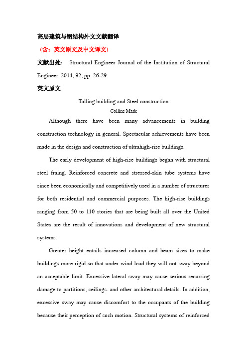
高层建筑与钢结构外文文献翻译(含:英文原文及中文译文)文献出处:Structural Engineer Journal of the Institution of Structural Engineer, 2014, 92, pp: 26-29.英文原文Talling building and Steel constructionCollins MarkAlthough there have been many advancements in building construction technology in general. Spectacular achievements have been made in the design and construction of ultrahigh-rise buildings.The early development of high-rise buildings began with structural steel fraing. Reinforced concrete and stressed-skin tube systems have since been economically and competitively used in a number of structures for both residential and commercial purposes. The high-rise buildings ranging from 50 to 110 stories that are being built all over the United States are the result of innovations and development of new structural systems.Greater height entails increased column and beam sizes to make buildings more rigid so that under wind load they will not sway beyond an acceptable limit. Excessive lateral sway may cause serious recurring damage to partitions, ceilings. and other architectural details. In addition, excessive sway may cause discomfort to the occupants of the building because their perception of such motion. Structural systems of reinforcedconcrete, as well as steel,take full advantage of inherent potential stiffness of the total building and therefore require additional stiffening to limit the sway.In a steel structure, for example, the economy can be defined in terms of the total average quantity of steel per square foot of floor area of the building. Curve A in Fig .1 represents the average unit weight of a conventional frame with increasing numbers of stories. Curve B represents the average steel weight if the frame is protected from all lateral loads. The gap between the upper boundary and the lower boundary represents the premium for height for the traditional column-and-beam frame. Structural engineers have developed structural systems with a view to eliminating this premium.Systems in steel. Tall buildings in steel developed as a result of several types of structural innovations. The innovations have been applied to the construction of both office and apartment buildings.Frame with rigid belt trusses. In order to tie the exterior columns of a frame structure to the interior vertical trusses, a system of rigid belt trusses at mid-height and at the top of the building may be used. A good example of this system is the First Wisconsin Bank Building(1974) in Milwaukee.Framed tube. The maximum efficiency of the total structure of a tall building, for both strength and stiffness,to resist wind load can beachieved only if all column element can be connected to each other in such a way that the entire building acts as a hollow tube or rigid box in projecting out of the ground. This particular structural system was probably used for the first time in the 43-story reinforced concrete DeWitt Chestnut Apartment Building in Chicago. The most significant use of this system is in the twin structural steel towers of the 110-story World Trade Center building in New YorkColumn-diagonal truss tube. The exterior columns of a building can be spaced reasonably far apart and yet be made to work together as a tube by connecting them with diagonal members interesting at the centre line of the columns and beams. This simple yet extremely efficient system was used for the first time on the John Hancock Centre in Chicago, using as much steel as is normally needed for a traditional 40-story building.Bundled tube. With the continuing need for larger and taller buildings, the framed tube or the column-diagonal truss tube may be used in a bundled form to create larger tube envelopes while maintaining high efficiency. The 110-story Sears Roebuck Headquarters Building in Chicago has nine tube, bundled at the base of the building in three rows. Some of these individual tubes terminate at different heights of the building, demonstrating the unlimited architectural possibilities of this latest structural concept. The Sears tower, at a height of 1450 ft(442m), is th e world’s tallest building.Stressed-skin tube system. The tube structural system was developed for improving the resistance to lateral forces (wind and earthquake) and the control of drift (lateral building movement ) in high-rise building. The stressed-skin tube takes the tube system a step further. The development of the stressed-skin tube utilizes the façade of the building as a structural element which acts with the framed tube, thus providing an efficient way of resisting lateral loads in high-rise buildings, and resulting in cost-effective column-free interior space with a high ratio of net to gross floor area.Because of the contribution of the stressed-skin façade, the framed members of the tube require less mass, and are thus lighter and less expensive. All the typical columns and spandrel beams are standard rolled shapes,minimizing the use and cost of special built-up members. The depth requirement for the perimeter spandrel beams is also reduced, and the need for upset beams above floors, which would encroach on valuable space, is minimized. The structural system has been used on the 54-story One Mellon Bank Center in Pittburgh.Systems in concrete. While tall buildings constructed of steel had an early start, development of tall buildings of reinforced concrete progressed at a fast enough rate to provide a competitive chanllenge to structural steel systems for both office and apartment buildings.Framed tube. As discussed above, the first framed tube concept fortall buildings was used for the 43-story DeWitt Chestnut Apartment Building. In this building ,exterior columns were spaced at 5.5ft (1.68m) centers, and interior columns were used as needed to support the 8-in . -thick (20-m) flat-plate concrete slabs.Tube in tube. Another system in reinforced concrete for office buildings combines the traditional shear wall construction with an exterior framed tube. The system consists of an outer framed tube of very closely spaced columns and an interior rigid shear wall tube enclosing the central service area. The system (Fig .2), known as the tube-in-tube system , made it possible to design the world’s present tallest (714ft or 218m)lightweight concrete building ( the 52-story One Shell Plaza Building in Houston) for the unit price of a traditional shear wall structure of only 35 stories.Systems combining both concrete and steel have also been developed, an examle of which is the composite system developed by skidmore, Owings &Merril in which an exterior closely spaced framed tube in concrete envelops an interior steel framing, thereby combining the advantages of both reinforced concrete and structural steel systems. The 52-story One Shell Square Building in New Orleans is based on this system.Steel construction refers to a broad range of building construction in which steel plays the leading role. Most steel construction consists oflarge-scale buildings or engineering works, with the steel generally in the form of beams, girders, bars, plates, and other members shaped through the hot-rolled process. Despite the increased use of other materials, steel construction remained a major outlet for the steel industries of the U.S, U.K, U.S.S.R, Japan, West German, France, and other steel producers in the 1970s.Early history. The history of steel construction begins paradoxically several decades before the introduction of the Bessemer and the Siemens-Martin (openj-hearth) processes made it possible to produce steel in quantities sufficient for structure use. Many of problems of steel construction were studied earlier in connection with iron construction, which began with the Coalbrookdale Bridge, built in cast iron over the Severn River in England in 1777. This and subsequent iron bridge work, in addition to the construction of steam boilers and iron ship hulls , spurred the development of techniques for fabricating, designing, and jioning. The advantages of iron over masonry lay in the much smaller amounts of material required. The truss form, based on the resistance of the triangle to deformation, long used in timber, was translated effectively into iron, with cast iron being used for compression members-i.e, those bearing the weight of direct loading-and wrought iron being used for tension members-i.e, those bearing the pull of suspended loading.The technique for passing iron, heated to the plastic state, betweenrolls to form flat and rounded bars, was developed as early as 1800;by 1819 angle irons were rolled; and in 1849 the first I beams, 17.7 feet (5.4m) long , were fabricated as roof girders for a Paris railroad station.Two years later Joseph Paxton of England built the Crystal Palace for the London Exposition of 1851. He is said to have conceived the idea of cage construction-using relatively slender iron beams as a skeleton for the glass walls of a large, open structure. Resistance to wind forces in the Crystal palace was provided by diagonal iron rods. Two feature are particularly important in the history of metal construction; first, the use of latticed girder, which are small trusses, a form first developed in timber bridges and other structures and translated into metal by Paxton ; and second, the joining of wrought-iron tension members and cast-iron compression members by means of rivets inserted while hot.In 1853 the first metal floor beams were rolled for the Cooper Union Building in New York. In the light of the principal market demand for iron beams at the time, it is not surprising that the Cooper Union beams closely resembled railroad rails.The development of the Bessemer and Siemens-Martin processes in the 1850s and 1860s suddenly open the way to the use of steel for structural purpose. Stronger than iron in both tension and compression ,the newly available metal was seized on by imaginative engineers, notably by those involved in building the great number ofheavy railroad bridges then in demand in Britain, Europe, and the U.S.A notable example was the Eads Bridge, also known as the St. Louis Bridge, in St. Louis (1867-1874), in which tubular steel ribs were used to form arches with a span of more than 500ft (152.5m). In Britain, the Firth of Forth cantilever bridge (1883-90) employed tubular struts, some 12 ft (3.66m) in diameter and 350 ft (107m) long. Such bridges and other structures were important in leading to the development and enforcement of standards and codification of permissible design stresses. The lack of adequate theoretical knowledge, and even of an adequate basis for theoretical studies, limited the value of stress analysis during the early years of the 20th century,as iccasionally failures,such as that of a cantilever bridge in Quebec in 1907,revealed.But failures were rare in the metal-skeleton office buildings;the simplicity of their design proved highly practical even in the absence of sophisticated analysis techniques. Throughout the first third of the century, ordinary carbon steel, without any special alloy strengthening or hardening, was universally used.The possibilities inherent in metal construction for high-rise building was demonstrated to the world by the Paris Exposition of 1889.for which Alexandre-Gustave Eiffel, a leading French bridge engineer, erected an openwork metal tower 300m (984 ft) high. Not only was theheight-more than double that of the Great Pyramid-remarkable, but the speed of erection and low cost were even more so, a small crewcompleted the work in a few months.The first skyscrapers. Meantime, in the United States another important development was taking place. In 1884-85 Maj. William Le Baron Jenney, a Chicago engineer , had designed the Home Insurance Building, ten stories high, with a metal skeleton. Jenney’s beams were of Bessemer steel, though his columns were cast iron. Cast iron lintels supporting masonry over window openings were, in turn, supported on the cast iron columns. Soild masonry court and party walls provided lateral support against wind loading. Within a decade the same type of construction had been used in more than 30 office buildings in Chicago and New York. Steel played a larger and larger role in these , with riveted connections for beams and columns, sometimes strengthened for wind bracing by overlaying gusset plates at the junction of vertical and horizontal members. Light masonry curtain walls, supported at each floor level, replaced the old heavy masonry curtain walls, supported at each floor level , replaced the old heavy masonry.Though the new construction form was to remain centred almost entirely in America for several decade, its impact on the steel industry was worldwide. By the last years of the 19th century, the basic structural shapes-I beams up to 20 in. ( 0.508m) in depth and Z and T shapes of lesser proportions were readily available, to combine with plates of several widths and thicknesses to make efficient members of any requiredsize and strength. In 1885 the heaviest structural shape produced through hot-rolling weighed less than 100 pounds (45 kilograms) per foot; decade by decade this figure rose until in the 1960s it exceeded 700 pounds (320 kilograms) per foot.Coincident with the introduction of structural steel came the introduction of the Otis electric elevator in 1889. The demonstration of a safe passenger elevator, together with that of a safe and economical steel construction method, sent building heights soaring. In New York the 286-ft (87.2-m) Flatiron Building of 1902 was surpassed in 1904 by the 375-ft (115-m) Times Building ( renamed the Allied Chemical Building) , the 468-ft (143-m) City Investing Company Building in Wall Street, the 612-ft (187-m) Singer Building (1908), the 700-ft (214-m) Metropolitan Tower (1909) and, in 1913, the 780-ft (232-m) Woolworth Building.The rapid increase in height and the height-to-width ratio brought problems. To limit street congestion, building setback design was prescribed. On the technical side, the problem of lateral support was studied. A diagonal bracing system, such as that used in the Eiffel Tower, was not architecturally desirable in offices relying on sunlight for illumination. The answer was found in greater reliance on the bending resistance of certain individual beams and columns strategically designed into the skeletn frame, together with a high degree of rigidity sought at the junction of the beams and columns. With today’s modern interiorlighting systems, however, diagonal bracing against wind loads has returned; one notable example is the John Hancock Center in Chicago, where the external X-braces form a dramatic part of the structure’s façade.World War I brought an interruption to the boom in what had come to be called skyscrapers (the origin of the word is uncertain), but in the 1920s New York saw a resumption of the height race, culminating in the Empire State Building in the 1931. The Empire State’s 102 stories (1,250ft. [381m]) were to keep it established as the hightest building in the world for the next 40 years. Its speed of the erection demonstrated how thoroughly the new construction technique had been mastered. A depot across the bay at Bayonne, N.J., supplied the girders by lighter and truck on a schedule operated with millitary precision; nine derricks powerde by electric hoists lifted the girders to position; an industrial-railway setup moved steel and other material on each floor. Initial connections were made by bolting , closely followed by riveting, followed by masonry and finishing. The entire job was completed in one year and 45 days.The worldwide depression of the 1930s and World War II provided another interruption to steel construction development, but at the same time the introduction of welding to replace riveting provided an important advance.Joining of steel parts by metal are welding had been successfully achieved by the end of the 19th century and was used in emergency ship repairs during World War I, but its application to construction was limited until after World War II. Another advance in the same area had been the introduction of high-strength bolts to replace rivets in field connections.Since the close of World War II, research in Europe, the U.S., and Japan has greatly extended knowledge of the behavior of different types of structural steel under varying stresses, including those exceeding the yield point, making possible more refined and systematic analysis. This in turn has led to the adoption of more liberal design codes in most countries, more imaginative design made possible by so-called plastic design ?The introduction of the computer by short-cutting tedious paperwork, made further advances and savings possible.中文译文高层结构与钢结构作者:Collins Mark近年来,尽管一般的建筑结构设计取得了很大的进步,但是取得显著成绩的还要属超高层建筑结构设计。
土木工程结构设计专业毕业设计英语翻译
XXXXXXXXX学院学士学位毕业设计(论文)英语翻译课题名称英语翻译学号学生专业、年级所在院系指导教师选题时间目录1、第一篇 (3)2、第二篇 (6)3、第三篇 (9)Concrete, Reinforced Concrete, and PrestressedConcreteConcrete is a stone like material obtained by permitting a carefully proportioned mixture of cement, sand and gravel or other aggregate, and water to harden in forms of the shape and dimensions of the desired structure. The bulk of the material consists of fine and coarse aggregate. Cement and water interact chemically to bind the aggregate particles into a solid mass. Additional water, over and above that needed for this chemical reaction, is necessary to give the mixture workability that enables it to fill the forms and surround the embedded reinforcing steel prior to hardening. Concretes with a wide range of properties can be obtained by appropriates adjustment of the proportions of the constituent materials. Special cements, special aggregates, and special curing methods permit an even wider variety of properties to be obtained.These properties depend to a very substantial degree on the proportions of the mix, on the thoroughness with which the various constituents are intermixed, and on the conditions of humidity and temperature in which the mix is maintained from the moment it is placed in the forms of humidity and hardened. The process of controlling conditions after placement is known as curing. To protect against the unintentional production of substandard concrete, a high degree of skillful control and supervision is necessary throughout the process, from the proportioning by weight of the individual components, trough mixing and placing, until the completion of curing.The factors that make concrete a universal building material are so pronounced that it has been used, in more primitive kinds and ways than at present, for thousands of years, starting with lime mortars from 12,000 to 600 B.C. in Crete, Cyprus, Greece, and the Middle East. The facility with which , while plastic, it can be deposited and made to fill forms or molds of almost any practical shape is one of these factors. Its high fire and weather resistance are evident advantages. Most of the constituent materials, with the exception of cement and additives, are usually available at low cost locally or at small distances from the construction site. Its compressive strength, like that of natural stones, is high, which makes it suitable for members primarily subject to compression, such as columns and arches. On the other hand, again as in natural stones, it is a relatively brittle material whose tensile strength is small compared with its compressive strength. This prevents its economical use in structural members that ate subject to tension either entirely or over part of their cross sections.To offset this limitation, it was found possible, in the second half of thenineteenth century, to use steel with its high tensile strength to reinforce concrete, chiefly in those places where its low tensile strength would limit the carrying capacity of the member. The reinforcement, usually round steel rods with appropriate surface deformations to provide interlocking, is places in the forms in advance of the concrete. When completely surrounded by the hardened concrete mass, it forms an integral part of the member. The resulting combination of two materials, known as reinforced concrete, combines many of the advantages of each: the relatively low cost , good weather and fire resistance, good compressive strength, and excellent formability of concrete and the high tensile strength and much greater ductility and toughness of steel. It is this combination that allows the almost unlimited range of uses and possibilities of reinforced concrete in the construction of buildings, bridges, dams, tanks, reservoirs, and a host of other structures.In more recent times, it has been found possible to produce steels, at relatively low cost, whose yield strength is 3 to 4 times and more that of ordinary reinforcing steels. Likewise, it is possible to produce concrete 4 to 5 times as strong in compression as the more ordinary concrete. These high-strength materials offer many advantages, including smaller member cross sections, reduced dead load, and longer spans. However, there are limits to the strengths of the constituent materials beyond which certain problems arise. To be sure, the strength of such a member would increase roughly in proportion to those of the materials. However, the high strains that result from the high stresses that would otherwise be permissible would lead to large deformations and consequently large deflections of such member under ordinary loading conditions. Equally important, the large strains in such high-strength reinforcing steel would induce large cracks in the surrounding low tensile strength concrete, cracks that would not only be unsightly but that could significantly reduce the durability of the structure. This limits the useful yield strength of high-strength reinforcing steel to 80 ksi according to many codes and specifications; 60 ksi steel is most commonly used.A special way has been found, however, to use steels and concrete of very high strength in combination. This type of construction is known as prestressed concrete. The steel, in the form of wires, strands, or bars, is embedded in the concrete under high tension that is held in equilibrium by compressive stresses in the concrete after hardening, Because of this precompression, the concrete in a flexural member will crack on the tension side at a much larger load than when not so precompressed. Prestressing greatly reduces both the deflections and the tensile cracks at ordinaryloads in such structures, and thereby enables these high-strength materials to be used effectively. Prestressed concrete has extended, to a very significant extent, the range of spans of structural concrete and the types of structures for which it is suited.混凝土,钢筋混凝土和预应力混凝土混凝土是一种经过水泥,沙子和砂砾或其他材料聚合得到经过细致配比的混合物,在液体变硬使材料石化后可以得到理想的形状和结构尺寸。
土木工程外文翻译---高层结构与钢结构
第五部分英文论文翻译Talling building and Steel constructionAlthough there have been many advancements in building construction technology in general. Spectacular archievements have been made in the design and construction of ultrahigh-rise buildings.The early development of high-rise buildings began with structural steel framing.Reinforced concrete and stressed-skin tube systems have since been economically and competitively used in a number of structures for both residential and commercial purposes.The high-rise buildings ranging from 50 to 110 stories that are being built all over the United States are the result of innovations and development of new structual systems.Greater height entails increased column and beam sizes to make buildings more rigid so that under wind load they will not sway beyond an acceptable limit.Excessive lateral sway may cause serious recurring damage to partitions,ceilings.and other architectural details. In addition,excessive sway may cause discomfort to the occupants of the building because their perception of such motion.Structural systems of reinforced concrete,as well as steel,take full advantage of inherent potential stiffness of the total building and therefore require additional stiffening to limit the sway.In a steel structure,forexample,the economy can be defined in terms of the total average quantity of steel per square foot of floor area of the building.Curve A in Fig .1 represents the average unit weight of a conventional frame with increasing numbers of stories. Curve B represents the average steel weight if the frame is protected from all lateral loads. The gap between the upper boundary and the lower boundary represents the premium for height for the traditional column-and-beam frame.Structural engineers have developed structural systems with a view to eliminating this premium.Systems in steel. Tall buildings in steel developed as a result of several types of structural innovations. The innovations have been applied to the construction of both office and apartment buildings.Frame with rigid belt trusses. In order to tie the exterior columns of a frame structure to the interior vertical trusses,a system of rigid belt trusses at mid-height and at the top of the building may be used. A good example of this system is the First Wisconsin Bank Building(1974) in Milwaukee.Framed tube. The maximum efficiency of the total structure of a tall building, for both strength and stiffness,to resist wind load can be achieved only if all column element can be connected to each other in such a way that the entire building acts as a hollow tube or rigid box in projecting out of the ground. This particular structural system was probably used for the first time in the 43-story reinforced concreteDeWitt Chestnut Apartment Building in Chicago. The most significant use of this system is in the twin structural steel towers of the 110-story World Trade Center building in New YorkColumn-diagonal truss tube. The exterior columns of a building can be spaced reasonably far apart and yet be made to work together as a tube by connecting them with diagonal members interesting at the centre line of the columns and beams. This simple yet extremely efficient system was used for the first time on the John Hancock Centre in Chicago, using as much steel as is normally needed for a traditional 40-story building.Bundled tube. With the continuing need for larger and taller buildings, the framed tube or the column-diagonal truss tube may be used in a bundled form to create larger tube envelopes while maintaining high efficiency. The 110-story Sears Roebuck Headquarters Building in Chicago has nine tube, bundled at the base of the building in three rows. Some of these individual tubes terminate at different heights of the building, demonstrating the unlimited architectural possibilities of this latest structural concept. The Sears tower, at a height of 1450 ft(442m), is the world’s tallest building.Stressed-skin tube system. The tube structural system was developed for improving the resistance to lateral forces (wind and earthquake) and the control of drift (lateral building movement ) in high-rise building. The stressed-skin tube takes the tube system a step further. The development of the stressed-skin tube utilizes the fa?ade of the building as a structural element which acts with the framed tube, thus providing an efficient way of resisting lateral loads in high-rise buildings, and resulting in cost-effective column-free interior space with a high ratio of net to gross floor area.Because of the contribution of the stressed-skin fa?ade, the framed members of the tube require less mass, and are thus lighter and less expensive. All the typical columns and spandrel beams are standard rolled shapes,minimizing the use and cost of special built-up members. The depth requirement for the perimeter spandrel beams is also reduced, and the need for upset beams above floors, which would encroach on valuable space, is minimized. The structural system has been used on the 54-story One Mellon Bank Center in Pittburgh.Systems in concrete.While tall buildings constructed of steel had an early start, development of tall buildings of reinforced concrete progressed at a fast enough rate to provide a competitive chanllenge to structural steel systems for both office and apartment buildings.Framed tube. As discussed above, the first framed tube concept for tall buildings was used for the 43-story DeWitt Chestnut Apartment Building. In this building ,exterior columns were spaced at 5.5ft (1.68m) centers, and interior columns were used as needed to support the 8-in . -thick (20-m) flat-plate concrete slabs.Tube in tube. Another system in reinforced concrete for office buildings combines the traditional shear wall construction with an exterior framed tube. The system consists of an outer framed tube of very closely spaced columns and aninterior rigid shear wall tube enclosing the central service area. The system (Fig .2), known as the tube-in-tube system , made it possible to design the world’s present tallest (714ft or 218m)lightweight concrete building ( the 52-story One Shell Plaza Building in Houston) for the unit price of a traditional shear wall structure of only 35 stories.Systems combining both concrete and steel have also been developed, an examle of which is the composite system developed by skidmore, Owings &Merril in which an exterior closely spaced framed tube in concrete envelops an interior steel framing, thereby combining the advantages of both reinforced concrete and structural steel systems. The 52-story One Shell Square Building in New Orleans is based on this system.Steel construction refers to a broad range of building construction in which steel plays the leading role. Most steel construction consists of large-scale buildings or engineering works, with the steel generally in the form of beams, girders, bars, plates, and other members shaped through the hot-rolled process. Despite the increased use of other materials, steel construction remained a major outlet for the steel industries of the U.S, U.K, U.S.S.R, Japan, West German, France, and other steel producers in the 1970s.Early history. The history of steel construction begins paradoxically several decades before the introduction of the Bessemer and the Siemens-Martin (openj-hearth) processes made it possible to produce steel in quantities sufficient for structure use. Many of problems of steel construction were studied earlier in connection with iron construction, which began with the Coalbrookdale Bridge, built in cast iron over the Severn River in England in 1777. This and subsequent iron bridge work, in addition to the construction of steam boilers and iron ship hulls , spurred the development of techniques for fabricating, designing, and jioning. The advantages of iron over masonry lay in the much smaller amounts of material required. The truss form, based on the resistance of the triangle to deformation, long used in timber, was translated effectively into iron, with cast iron being used for compression members-i.e, those bearing the weight of direct loading-and wrought iron being used for tension members-i.e, those bearing the pull of suspended loading.The technique for passing iron, heated to the plastic state, between rolls to form flat and rounded bars, was developed as early as 1800;by 1819 angle irons were rolled; and in 1849 the first I beams, 17.7 feet (5.4m) long , were fabricated as roof girders for a Paris railroad station.Two years later Joseph Paxton of England built the Crystal Palace for the London Exposition of 1851. He is said to have conceived the idea of cage construction-using relatively slender iron beams as a skeleton for the glass walls of a large, open structure. Resistance to wind forces in the Crystal palace was provided by diagonal iron rods. Two feature are particularly important in the history of metal construction; first, the use of latticed girder, which are small trusses, a form first developed in timber bridges and other structures and translated into metal by Paxton ; and second, the joining of wrought-iron tension members and cast-ironcompression members by means of rivets inserted while hot.In 1853 the first metal floor beams were rolled for the Cooper Union Building in New York. In the light of the principal market demand for iron beams at the time, it is not surprising that the Cooper Union beams closely resembled railroad rails.The development of the Bessemer and Siemens-Martin processes in the 1850s and 1860s suddenly open the way to the use of steel for structural purpose. Stronger than iron in both tension and compression ,the newly available metal was seized on by imaginative engineers, notably by those involved in building the great number of heavy railroad bridges then in demand in Britain, Europe, and the U.S.A notable example was the Eads Bridge, also known as the St. Louis Bridge, in St. Louis (1867-1874), in which tubular steel ribs were used to form arches with a span of more than 500ft (152.5m). In Britain, the Firth of Forth cantilever bridge (1883-90) employed tubular struts, some 12 ft (3.66m) in diameter and 350 ft (107m) long. Such bridges and other structures were important in leading to the development and enforcement of standards and codification of permissible design stresses. The lack of adequate theoretical knowledge, and even of an adequate basis for theoretical studies, limited the value of stress analysis during the early years of the 20th century,asiccasionallyfailures,such as that of a cantilever bridge in Quebec in 1907,revealed.But failures were rare in the metal-skeleton office buildings;the simplicity of their design proved highly practical even in the absence of sophisticated analysis techniques. Throughout the first third of the century, ordinary carbon steel, without any special alloy strengthening or hardening, was universally used.The possibilities inherent in metal construction for high-rise building was demonstrated to the world by the Paris Exposition of 1889.for which Alexandre-Gustave Eiffel, a leading French bridge engineer, erected an openwork metal tower 300m (984 ft) high. Not only was the height-more than double that of the Great Pyramid-remarkable, but the speed of erection and low cost were even more so, a small crew completed the work in a few months.The first skyscrapers. Meantime, in the United States another important development was taking place. In 1884-85 Maj. William Le Baron Jenney, a Chicago engineer , had designed the Home Insurance Building, ten stories high, with a metal skeleton. Jenney’s beams were of Bessemer steel, though his columns were cast iron. Cast iron lintels supporting masonry over window openings were, in turn, supported on the cast iron columns. Soild masonry court and party walls provided lateral support against wind loading. Within a decade the same type of construction had been used in more than 30 office buildings in Chicago and New York. Steel played a larger and larger role in these , with riveted connections for beams and columns, sometimes strengthened for wind bracing by overlaying gusset plates at the junction of vertical and horizontal members. Light masonry curtain walls, supported at each floor level, replaced the old heavy masonry curtain walls, supported at each floor level , replaced the old heavy masonry.Though the new construction form was to remain centred almost entirely in America for several decade, its impact on the steel industry was worldwide. By thelast years of the 19th century, the basic structural shapes-I beams up to 20 in. ( 0.508m) in depth and Z and T shapes of lesser proportions were readily available, to combine with plates of several widths and thicknesses to make efficient members of any required size and strength. In 1885 the heaviest structural shape produced through hot-rolling weighed less than 100 pounds (45 kilograms) per foot; decade by decade this figure rose until in the 1960s it exceeded 700 pounds (320 kilograms) per foot.Coincident with the introduction of structural steel came the introduction of the Otis electric elevator in 1889. The demonstration of a safe passenger elevator, together with that of a safe and economical steel construction method, sent building heights soaring. In New York the 286-ft (87.2-m) Flatiron Building of 1902 was surpassed in 1904 by the 375-ft (115-m) Times Building ( renamed the Allied Chemical Building) , the 468-ft (143-m) City Investing Company Building in Wall Street, the 612-ft (187-m) Singer Building (1908), the 700-ft (214-m) Metropolitan Tower (1909) and, in 1913, the 780-ft (232-m) Woolworth Building.The rapid increase in height and the height-to-width ratio brought problems. To limit street congestion, building setback design was prescribed. On the technical side, the problem of lateral support was studied. A diagonal bracing system, such as that used in the Eiffel Tower, was not architecturally desirable in offices relying on sunlight for illumination. The answer was found in greater reliance on the bending resistance of certain individual beams and columns strategically designed into the skeletn frame, together with a high degree of rigidity sought at the junction of the beams and columns. With today’s modern interior lighting systems, however, diagonal bracing against wind loads has returned; one notable example is the John Hancock Center in Chicago, where the external X-braces form a dramatic part of the structure’s fa?ade.World War I brought an interruption to the boom in what had come to be called skyscrapers (the origin of the word is uncertain), but in the 1920s New York saw a resumption of the height race, culminating in the Empire State Building in the 1931. The Empire State’s 102 stories (1,250ft. [381m]) were to keep it established as the hightest building in the world for the next 40 years. Its speed of the erection demonstrated how thoroughly the new construction technique had been mastered. A depot across the bay at Bayonne, N.J., supplied the girders by lighter and truck on a schedule operated with millitary precision; nine derricks powerde by electric hoists lifted the girders to position; an industrial-railway setup moved steel and other material on each floor. Initial connections were made by bolting , closely followed by riveting, followed by masonry and finishing. The entire job was completed in one year and 45 days.The worldwide depression of the 1930s and World War II provided another interruption to steel construction development, but at the same time the introduction of welding to replace riveting provided an important advance.Joining of steel parts by metal are welding had been successfully achieved by the end of the 19th century and was used in emergency ship repairs during World War I, but its application to construction was limited until after World War II.Another advance in the same area had been the introduction of high-strength bolts toreplace rivets in field connections.Since the close of World War II, research in Europe, the U.S., and Japan has greatly extended knowledge of the behavior of different types of structural steelunder varying stresses, including those exceeding the yield point, making possiblemore refined and systematic analysis. This in turn has led to the adoption of moreliberal design codes in most countries, more imaginative design made possible byso-called plastic design ?The introduction of the computer by short-cutting tediouspaperwork, made further advances and savings possible.高层结构与钢结构近年来,尽管一般的建筑结构设计取得了很大的进步,但是取得显著成绩的还要属超高层建筑结构设计。
建筑钢结构工程技术 钢结构施工英语常用词汇
钢结构施工常用英语总结标题类:Construction Organization Plan施工组织设计General Construction Organization Plan施工组织总设计Compilation Instructions 编制说明Compilation Bases 编制依据Construction Scheme施工方案Construction Arrangement 施工部署Preparation Of Construction Site施工现场准备Labor Force Organization劳动力组织Project Management Organization项目管理组织机构Construction Schedule 施工进度计划(Construction Progress Scheduling)Measures To Ensure Construction Progress 进度保证措施Schedule Management Plan 进度管理计划Construction Site Layout Plan 施工现场平面布置Construction Procedures施工程序Quality Assurance System质量保证体系Construction Surveying, Positioning And Setting Out施工测量、定位放线Preliminaries 准备工作Mounting And Installation 装配和安装Steel Structure Installation Method钢结构安装方法Preparations Prior To Installation安装前准备工作Consideration About Installation Of Steel Structure钢结构安装思路A Standard Portal-Framed Structure标准门式钢架Two-Crane-Lifting-Method双机抬吊法The Longitudinal And Transverse Axis纵横轴线After The Steel Beam Positioned钢梁就位后Trial Hoist试吊Major Safety Technical Measures主要安全技术措施设备(Equipment):Hammerhead Tower Crane 平头塔吊Mobile Tower Crane 移动塔吊(Traveling Tower Crane)Luffing Jib Tower Crane 动臂塔吊Crawler Crane 履带吊Mobile Crane/ Auto Crane 汽车吊Flatbed Trailer平板拖车Forklift 叉车Jack 千斤顶Lifting Jack 提升千斤顶Anchorage 锚具Scissor Lift剪叉式升降机Manlift 举人车Chevron Bracing人字支撑Sling吊索Steel Grating 钢格栅板Measuring Instrument计量工具小型工机具(tools):焊机welding machine自动焊机automatic welding machine自动埋弧焊机submerged arc automatic welding machine手动电弧焊机manual arc welding machine二氧化碳埋弧焊机CO2 (carbon dioxide)shield arc welding machine 电渣焊机electro-slag welding machine焊条electrode锤子hummer力矩扳手torque spanner,torque wrench活动扳手the flexible spanner螺丝钳clamp电钻electric drill钻机driller冲击钻(电锤)electric hammer手动摇臂钻manually operated whipping driller 磁力钻magnetic driller铣床milling machine碘钨灯iodine tungsten lamp安全照明灯safety flare空压机air compressor钢丝绳steel cable/steel wire钢绞线steel strand吊钩crane hook液压校直机hydraulic calibrator经纬仪theodolite水平仪(水准仪)gradienter,level安全防护:安全网safety net安全帽helmet安全带safety belt劳保鞋safety shoes护目镜goggles防护罩shield安全手套safety gloves防护手套protective gloves绝缘工作服insulating coverall耐火工作服fire-resistance coverall耐酸工作服acid-proof working suit耳塞earplug其它:Component 部件Element 构件steel component/steel member钢构件primary structure 主结构substructure 次结构secondary structure二级结构on-site 现场的assembly yard 拼装场地storage yard堆场trial assembly 试装erection stage 安装阶段partial penetrated butt weld 部分熔透对接焊缝full penetrated butt weld 全熔透对接焊缝Bracket 牛腿padding plate 垫板bearing plate 支承板bearing stiffener 支承加劲肋high-strength bolt 高强螺栓hinged connection 铰接lattice column格构柱lacing bar 缀条solid-web steel column 实腹式钢柱the steel column with bracket带牛腿钢柱support 支撑架Loose pieces散件(海运中散件用bulk/bulking,如散货运输bulk transport)Quantity 数量Spec. 规格Nos. 件/个数Sets 套/台Usage 用途Drawing (DWG) 图纸View 视图Elevation 立面图Section 断面图Plan 平面图Detail 详图Location 位置Layout规划图detailed drawing细节图shop drawing深化图纸primer coat 底漆intermediate coat中间漆top coat/finishing coat 面漆apply 涂, apply primers 涂底漆dry film 干膜initial tighten 初紧final tighten 终紧removing rust 除锈polish 打磨anti-corrosion paint防腐油漆fireproof paint防火涂料(fire resistive coating)ex-factory quality certificate出厂质量合格证书Welder should bearing the qualification certificate焊工必须具有上岗证常用表格:Company Organization ChartProject Organization Chart。
土木工程常用英语翻译
土木工程常用翻译工程结构 buildin g and civil enginee ring structu res房屋建筑和土木工程的建筑物、构筑物及其相关组成部分的总称。
工程结构设计designof buildin g and civil enginee ringstructu res在工程结构的可靠与经济、适用与美观之间,选择一种最佳的合理的平衡,使所建造的结构能满足各种预定功能要求。
房屋建筑工程buildin g enginee ring一般称建筑工程,为新建、改建或扩建房屋建筑物和附属构筑物所进行的勘察、规划、设计、施工、安装和维护等各项技术工作和完成的工程实体。
土木工程 civil enginee ring除房屋建筑外,为新建、改建或扩建各类工程的建筑物、构筑物和相关配套设施等所进行的勘察、规划、设计、施工、安装和维护等各项技术工作和完成的工程实体。
公路工程 highway enginee ring为新建或改建各级公路和相关配套设施等而进行的勘察、规划、设计、施工、安装和维护等各项技术工作和完成的工程实体。
铁路工程 railway enginee ring为新建或改建铁路和相关配套设施等所进行的勘察、规划、设计、施工、安装和维护等各项技术工作和完成的工程实体。
港口与航道工程 port ( harbour ) and waterwa y enginee ring为新建或改建港口与航道和相关配套设施等所进行的勘察、规划、设计、施工、安装和维护等各项技术工作和完成的工程实体。
水利工程 hydraul ic enginee ring为修建治理水患、开发利用水资源的各项建筑物、构筑物和相关配设施等所进行的勘察、规划、设计、施工、安装和维护等各项技术工作和完成的工程实体。
钢结构桥梁中英文对照外文翻译文献
中英文对照外文翻译文献(文档含英文原文和中文翻译)Recent Research and Design Developments in Steel and Composite Steel-concrete Structures in USAThe paper will conclude with a look toward the future of structural steel research.1. Research on steel bridgesThe American Association of State Transportation and Highway Officials (AASTHO) is the authority that promulgates design standards for bridges in the US. In 1994 it has issued a new design specification which is a Limit States Design standard that is based on the principles of reliability theory. A great deal of work went into the development of this code in the past decade, especially on calibration and on the probabilistic evaluation of the previous specification. The code is now being implemented in the design office, together with the introduction of the SystemeInternationale units. Many questions remain open about the new method of design, and there are many new projects that deal with the reliability studies of the bridge as a system. One such current project is a study to develop probabilistic models, load factors, and rational load-combination rules for the combined effects of live-load and wind; live-load and earthquake; live-load, wind and ship collision; and ship collision, wind, and scour. There are also many field measurements of bridge behavior, using modern tools of inspection and monitoring such as acoustic emission techniques and other means of non-destructive evaluation. Such fieldwork necessitates parallel studies in the laboratory, and the evolution of ever more sophisticated high-technology data transmission methods.America has an aging steel bridge population and many problems arise from fatigue and corrosion. Fatigue studies on full-scale components of the Williamsburg Bridge in New York have recently been completed at Lehigh University. A probabilistic AASTHO bridge evaluation regulation has been in effect since 1989, and it is employed to assess the future useful life of structures using rational methods that include field observation and measurement together with probabilistic analysis. Such an activity also fosters additional research because many issues are still unresolved. One such area is the study of the shakedown of shear connectors in composite bridges. This work has been recently completed at the University of Missouri.In addition to fatigue and corrosion, the major danger to bridges is the possibility of earthquake induced damage. This also has spawned many research projects on the repair and retrofit of steel superstructures and the supporting concrete piers. Many bridges in the country are being strengthened for earthquake resistance. One area that is receiving much research attention is the strengthening of concrete piers by "jacketing" them by sheets of high-performance reinforced plastic.The previously described research deals mainly with the behavior of existing structures and the design of new bridges. However, there is also a vigorous activity on novel bridge systems. This research is centered on the application of high-performance steels for the design of innovative plate and box-girder bridges, such as corrugated webs, combinations of open and closed shapes, and longer spansfor truss bridges. It should be mentioned here that, in addition to work on steel bridges, there is also very active research going on in the study of the behavior of prestressed concrete girders made from very high strength concrete. The performance and design of smaller bridges using pultruded high-performance plastic composite members is also being studied extensively at present. New continuous bridge systems with steel concrete composite segments in both the positive moment and the negative moment regions are being considered. Several researchers have developed strong capabilities to model the three-dimensional non-linear behavior of individual plate girders, and many studies are being performed on the buckling and post-buckling characteristics of such panion experimental studies are also made,especially on members built from high-performance steels. A full-scale bridge of such steel has been designed, and will soon be constructed and then tested under traffic loading. Research efforts are also underway on the study of the fatigue of large expansion joint elements and on the fatigue of highway sign structures.The final subject to be mentioned is the resurgence of studies of composite steel concrete horizontally curved steel girder bridges. A just completed project at the University of Minnesota monitored the stresses and the deflections in a skewed and curved bridge during all phases of construction, starting from the fabrication yard to the completed bridge.~ Excellent correlation was found to exist between the measured stresses and deformations and the calculated values. The stresses and deflections during construction were found to be relatively small, that is, the construction process did not cause severe trauma to the system. The bridge has now been tested under service loading, using fully loaded gravel trucks, for two years, and it will continue to be studied for further years to measure changes in performance under service over time. A major testing project is being conducted at the Federal Highway Administration laboratory in Washington, DC, where a half-scale curved composite girder bridge is currently being tested to determine its limit states. The test-bridge was designed to act as its own test-frame, where various portions can be replaced after testing. Multiple flexure tests, shear tests, and tests under combined bending and shear, are thus performed with realistic end-conditions and restraints. The experiments arealso modeled by finite element analysis to check conformance between reality and prediction. Finally design standards will be evolved from the knowledge gained. This last project is the largest bridge research project in the USA at the present time.From the discussion above it can be seen that even though there is no large expansion of the nation's highway and railroad system, there is extensive work going on in bridge research. The major challenge facing both the researcher and the transportation engineer is the maintenance of a healthy but aging system, seeing to its gradual replacement while keeping it safe and serviceable.2. Research on steel members and framesThere are many research studies on the strength and behavior of steel building structures. The most important of these have to do with the behavior and design of steel structures under severe seismic events. This topic will be discussed later in this paper. The most significant trends of the non-seismic research are the following: "Advanced" methods of structural analysis and design are actively studied at many Universities, notably at Cornell, Purdue, Stanford, and Georgia Tech Universities. Such analysis methods are meant to determine the load-deformation behavior of frames up to and beyond failure, including inelastic behavior, force redistribution, plastic hinge formation, second-order effects and frame instability. When these methods are fully operational, the structure will not have to undergo a member check, because the finite element analysis of the frame automatically performs this job. In addition to the research on the best approaches to do this advanced analysis, there are also many studies on simplifications that can be easily utilized in the design office while still maintaining the advantages of a more complex analysis. The advanced analysis method is well developed for in-plane behavior, but much work is yet to be done on the cases where bi-axial bending or lateraltorsional buckling must be considered. Some successes have been achieved, but the research is far from complete.Another aspect of the frame behavior work is the study of the frames with semirigid joints. The American Institute of Steel Construction (AISC) has published design methods for office use. Current research is concentrating on the behavior ofsuch structures under seismic loading. It appears that it is possible to use such frames in some seismic situations, that is, frames under about 8 to 10 stories in height under moderate earthquake loads. The future of structures with semi-rigid frames looks very promising, mainly because of the efforts of researchers such as Leon at Georgia Tech University, and many others.Research on member behavior is concerned with studying the buckling and post buckling behavior of compact angle and wide-flange beam members by advanced commercial finite element programs. Such research is going back to examine the assumptions made in the 1950s and 1960s when the plastic design compactness and bracing requirements were first formulated on a semi-empirical basis. The non-linear finite element computations permit the "re-testing" of the old experiments and the performing of new computer experiments to study new types of members and new types of steels. White of Georgia Tech is one of the pioneers in this work. Some current research at the US military Academy and at the University of Minnesota by Earls is discussed later in this report. The significance of this type of research is that the phenomena of extreme yielding and distortion can be efficiently examined in parameter studies performed on the computer. The computer results can be verified with old experiments, or a small number of new experiments. These studies show a good prospect fornew insights into old problems that heretofore were never fully solved.3. Research on cold-formed steel structuresNext to seismic work, the most active part of research in the US is on cold-formed steel structures. The reason for this is that the supporting industry is expanding, especially in the area of individual family dwellings. As the cost of wood goes up, steel framed houses become more and more economical. The intellectual problems of thin-walled structures buckling in multiple modes under very large deformations have attracted some of the best minds in stability research. As a consequence, many new problems have been solved: complex member stiffening systems, stability and bracing of C and Z beams, composite slabs, perforated columns, standing-seam roof systems, bracing and stability of beams with very complicatedshapes, cold-formed members with steels of high yield stress-to-tensile strength ratio, and many other interesting applications. The American Iron and Steel Institute (AISI) has issued a new expanded standard in 1996 that brought many of these research results into the hands of the designer.4. Research on steel-concrete composite structuresAlmost all structural steel bridges and buildings in the US are built with composite beams or girders. In contrast, very few columns are built as composite members. The area of composite Column research is very active presently to fill up the gap of technical information on the behavior of such members. The subject of steel tubes filled with high-strength concrete is especially active. One of the aims of research performed by Hajjar at the University of Minnesota is to develop a fundamental understanding of the various interacting phenomena that occur in concrete-filled columns and beam-columns under monotonic and cyclic load. The other aim is to obtain a basic understanding of the behavior of connections of wide-flange beams to concrete filled tubes.Other major research work concerns the behavior and design of built-up composite wide-flange bridge girders under both positive and negative bending. This work is performed by Frank at the University of Texas at Austin and by White of Georgia Tech, and it involves extensive studies of the buckling and post-buckling of thin stiffened webs. Already mentioned is the examination of the shakedown of composite bridges. The question to be answered is whether a composite bridge girder loses composite action under repeated cycles of loads which are greater than the elastic limit load and less than the plastic mechanism load. A new study has been initiated at the University of Minnesota on the interaction between a semi-rigid steel frame system and a concrete shear wall connected by stud shear connectors.5. Research on connectionsConnection research continues to interest researchers because of the great variety of joint types. The majority of the connection work is currently related to the seismic problems that will be discussed in the next section of this paper. The most interest in non-seismic connections is the characterization of the monotonic moment-rotationbehavior of various types of semi-rigid joints.6. Research on structures and connections subject to seismic forcesThe most compelling driving force for the present structural steel research effort in the US was the January 17, 1994 earthquake in Northridge, California, North of Los Angeles. The major problem for steel structures was the extensive failure of prequalified welded rigid joints by brittle fracture. In over 150 buildings of one to 26 stories high there were over a thousand fractured joints. The buildings did not collapse, nor did they show any external signs of distress, and there were no human injuries or deaths. A typical joint is shown in Fig. 2.2.1.In this connection the flanges of the beams are welded to the flanges of the column by full-penetration butt welds. The webs are bolted to the beams and welded to the columns. The characteristic features of this type of connection are the backing bars at the bottom of the beam flange, and the cope-holes left open to facilitate the field welding of the beam flanges. Fractures occurred in the welds, in the beam flanges, and/or in the column flanges, sometimes penetrating into the webs.Once the problem was discovered several large research projects were initiated at various university laboratories, such as The University of California at San Diego, the University of Washington in Seattle, the University of Texas at Austin, Lehigh University at Bethlehem, Pennsylvania, and at other places. The US Government under the leadership of the Federal Emergency Management Agency (FEMA) instituted a major national research effort. The needed work was deemed so extensivethat no single research agency could hope to cope with it. Consequently three California groups formed a consortium which manages the work:(1) Structural Engineering Association of California.(2) Applied Technology Council.(3) California Universities for Research in Earthquake Engineering.The first letters in the name of each agency were combined to form the acronym SAC, which is the name of the joint venture that manages the research. We shall read much from this agency as the results of the massive amounts of research performed under its aegis are being published in the next few years.The goals of the program are to develop reliable, practical and cost-effective guidelines for the identification and inspection of at-risk steel moment frame buildings, the repair or upgrading of damaged buildings, the design of new construction, and the rehabilitation of undamaged buildings.~ As can be seen, the scope far exceeds the narrow look at the connections only. The first phase of the research was completed at the end of 1996, and its main aim was to arrive at interim guidelines so that design work could proceed. It consisted of the following components:~ A state-of-the-art assessment of knowledge on steel connections.~ A survey of building damage.~ The evaluation of ground motion.~ Detailed building analyses and case studies.~ A preliminary experimental program.~ Professional training and quality assurance programs.~ Publishing of the Interim Design Guidelines.A number of reports were issued in this first phase of the work. A partial list of these is appended at the end of this paper.During the first phase of the SAC project a series of full-scale connection tests under static and, occasionally, dynamic cyclic tests were performed. Tests were of pre-Northridge-type connections (that is, connections as they existed at the time of the earthquake), of repaired and upgraded details, and of new recommendedconnection details. A schematic view of the testing program is illustrated in Fig.2.2.2 Some recommended strategies for new design are schematically shown in Fig. 2.2.3.Fig. 2.2.3 some recommended improvements in the interim guidelinesThe following possible causes, and their combinations, were found to have contributed to tile connection failures:~ Inadequate workmanship in the field welds.~ Insufficient notch-toughness of the weld metal.~ Stress raisers caused by the backing bars.~ Lack of complete fusion near the backing bar.~ Weld bead sizes were too big.~ Slag inclusion in the welds.While many of the failures can be directly attributed to the welding and thematerial of the joints, there are more serious questions relative to the structural system that had evolved over the years mainly based on economic considerations.' The structural system used relatively few rigid-frames of heavy members that were designed to absorb the seismic forces for large parts of the structure. These few lateral-force resistant frames provide insufficient redundancy. More rigid-frames with smaller members could have provided a tougher and more ductile structural system. There is a question of size effect: Test results from joints of smaller members were extrapolated to joints with larger members without adequate test verification. The effect of a large initial pulse may have triggered dynamic forces that could have caused brittle fracture in joints with fracture critical details and materials. Furthermore, the yield stress of the beams was about 30% to 40% larger than the minimum specified values assumed in design, and so the connection failed before the beams, which were supposed to form plastic hinges.As can be seen, there are many possible reasons for this massive failure rate, and there is blame to go around for everyone. No doubt, the discussion about why and how the joints failed will go on for many more years. The structural system just did not measure up to demands that were more severe than expected. What should be kept in mind, however, is that no structure collapsed or caused even superficial nonstructural damage, and no person was injured or killed. In the strictest sense the structure sacrificed itself so that no physical harm was done to its users. The economic harm, of course, was enormous.7. Future directions of structural steel research and conclusionThe future holds many challenges for structural steel research. The ongoing work necessitated by the two recent earthquakes that most affected conventional design methods, namely, the Northridge earthquake in the US and the Kobe earthquake in Japan, will continue well into the first decade of the next Century. It is very likely that future disasters of this type will bring yet other problems to the steel research community. There is a profound change in the philosophy of design for disasters: We can no longer be content with saving lives only, but we must also design structures which will not be so damaged as to require extensive repairs.Another major challenge will be the emergence of many new materials such as high-performance concrete and plastic composite structures. Steel structures will continually have to face the problem of having to demonstrate viability in the marketplace. This can only be accomplished by more innovative research. Furthermore, the new comprehensive limit-states design codes which are being implemented worldwide, need research to back up the assumptions used in the theories.Specifically, the following list highlights some of the needed research in steel structures:Systems reliability tools have been developed to a high degree of sophistication. These tools should be applied to the studies of bridge and building structures to define the optimal locations of monitoring instruments, to assess the condition and the remaining life of structures, and to intelligently design economic repair and retrofit operations.New developments in instrumentation, data transfer and large-scale computation will enable researchers to know more about the response of structures under severe actions, so that a better understanding of "real-life" behavior can be achieved.The state of knowledge about the strength of structures is well above the knowledge about serviceability and durability. Research is needed on detecting and preventing damage in service and from deterioration.The areas of fatigue and fracture mechanics on the one hand, and the fields of structural stability on the other hand, should converge into a more Unified conceptual entity.The problems resulting from the combination of inelastic stability and low-cycle fatigue in connections subject to severe cyclic loads due to seismic action will need to be solved.The performance of members, connections and connectors (e.g., shear connectors) under severe cyclic and dynamic loading requires extensive new research, including shakedown behavior.The list could go on, but one should never be too dogmatic about the future ofsuch a highly creative activity as research. Nature, society and economics will provide sufficient challenges for the future generation of structural engineers.近期美国在钢结构和钢筋混凝土结构研究和设计方面的发展这篇文章将总结对钢结构的研究展望.1.钢结构桥梁的研究美国国家运输和公路官员协会(AASTH0)是为美国桥梁发布设计标准的权威。
钢结构常用词汇中英文对照
钢结构常用词汇中英文对照plasticity 塑性toughness 韧性radius of gyration回转半径end tab 引弧(出)板rimming steel沸腾钢riveted connection 铆钉连接fully-killed steel镇静钢welded connection 焊缝连接semi-killed steel半镇静钢bolted connection 螺栓连接special killed steel特殊镇静钢fillet weld 角焊缝deoxidizer 脱氧剂butt weld 对接焊缝cold bending property 冷弯性能oblique-angle fillet weld 斜角角焊缝impact toughness 冲击韧性right-angle/orthogonal fillet weld直角角焊缝elongation 伸长率penetrated butt weld 透焊对接焊缝slenderness ratio 长细比partial penetrated butt weld 不焊透对接焊缝deflection 挠度metallurgical quality 冶金质量stiffness 刚度weld crack 焊接裂纹stability 稳定性weld defects 焊接缺陷outstanding width of flange 翼缘板外伸宽度weld roof 焊根outstanding width of stiffener 加劲肋外伸宽度weld toe 焊趾transverse stiffener 横向加劲肋welding flux 焊剂effective length 计算长度welding rod/electrode 焊条Euler’s critical load 欧拉临界力welding wire 焊丝effective cross-section area of bolt 螺栓有效截面面积effective thickness of fillet weld 角焊缝有效厚度parallel arrangement 并列排列staggered arrangement 错列排列high-strength bolt 高强度螺栓lateral bending 侧向弯曲friction-type high-strength bolt connection 摩擦型高强度螺栓连接Bearing-type high-strength bolt connection 承压型高强度螺栓连接leg size of fillet weld 角焊缝焊脚尺寸longitudinal weld 纵向焊缝hot brittleness 热脆cold brittleness 冷脆blue brittleness 蓝脆Ultimate Limit States 承载能力极限状态Serviceability Limit States正常使用极限状态design value of strength 强度设计值characteristic value of strength 强度标准值static load静载dynamic load 动载。
土木工程专业毕业设计外文文献翻译2篇
土木工程专业毕业设计外文文献翻译2篇XXXXXXXXX学院学士学位毕业设计(论文)英语翻译课题名称英语翻译学号学生专业、年级所在院系指导教师选题时间Fundamental Assumptions for Reinforced ConcreteBehaviorThe chief task of the structural engineer is the design of structures. Design is the determination of the general shape and all specific dimensions of a particular structure so that it will perform the function for which it is created and will safely withstand the influences that will act on it throughout useful life. These influences are primarily the loads and other forces to which it will be subjected, as well as other detrimental agents, such as temperature fluctuations, foundation settlements, and corrosive influences, Structural mechanics is one of the main tools in this process of design. As here understood, it is the body of scientific knowledge that permits one to predict with a good degree of certainly how a structure of give shape and dimensions will behave when acted upon by known forces or other mechanical influences. The chief items of behavior that are of practical interest are (1) the strength of the structure, i. e. , that magnitude of loads of a give distribution which will cause the structure to fail, and (2) the deformations, such as deflections and extent of cracking, that the structure will undergo when loaded underservice condition.The fundamental propositions on which the mechanics of reinforced concrete is based are as follows:1.The internal forces, such as bending moments, shear forces, and normal andshear stresses, at any section of a member are in equilibrium with the effect of the external loads at that section. This proposition is not an assumption but a fact, because any body or any portion thereof can be at rest only if all forces acting on it are in equilibrium.2.The strain in an embedded reinforcing bar is the same as that of thesurrounding concrete. Expressed differently, it is assumed that perfect bonding exists between concrete and steel at the interface, so that no slip can occur between the two materials. Hence, as the one deforms, so must the other. With modern deformed bars, a high degree of mechanical interlocking is provided in addition to the natural surface adhesion, so this assumption is very close to correct.3.Cross sections that were plane prior to loading continue to be plan in themember under load. Accurate measurements have shown that when a reinforced concrete member is loaded close to failure, this assumption is not absolutely accurate. However, the deviations are usually minor.4.In view of the fact the tensile strength of concrete is only a small fraction ofits compressive strength; the concrete in that part of a member which is in tension is usually cracked. While these cracks, in well-designed members, are generally so sorrow as to behardly visible, they evidently render the cracked concrete incapable of resisting tension stress whatever. This assumption is evidently a simplification of the actual situation because, in fact, concrete prior to cracking, as well as the concrete located between cracks, does resist tension stresses of small magnitude. Later in discussions of the resistance of reinforced concrete beams to shear, it will become apparent that under certain conditions this particular assumption is dispensed with and advantage is taken of the modest tensile strength that concrete can develop.5.The theory is based on the actual stress-strain relation ships and strengthproperties of the two constituent materials or some reasonable equivalent simplifications thereof. The fact that novelistic behavior is reflected in modern theory, that concrete is assumed to be ineffective in tension, and that the joint action of the two materials is taken into consideration results in analytical methods which are considerably more complex and also more challenging, than those that are adequate for members made of a single, substantially elastic material.These five assumptions permit one to predict by calculation the performance of reinforced concrete members only for some simple situations. Actually, the joint action of two materials as dissimilar and complicated as concrete and steel is so complex that it has not yet lent itself to purely analytical treatment. For this reason, methods of design and analysis, while using these assumptions, are very largely based on the results of extensive and continuing experimental research. They are modified and improved as additional test evidence becomes available.钢筋混凝土的基本假设作为结构工程师的主要任务是结构设计。
外文翻译---高层结构与钢结构
英文译文T alling building and Steel constructionAlthough there have been many advancements in building construction technology in general. Spectacular archievements have been made in the design and construction of ultrahigh-rise buildings.The early development of high-rise buildings began with structural steel framing.Reinforced concrete and stressed-skin tube systems have since been economically and competitively used in a number of structures for both residential and commercial purposes.The high-rise buildings ranging from 50 to 110 stories that are being built all over the United States are the result of innovations and development of new structual systems.Gr eater height entails increased column and beam sizes to make buildings more rigid so that under wind load they will not sway beyond an acceptable limit.Excessive lateral sway may cause serious recurring damage to partitions,ceilings.and other architectural details. In addition,excessive sway may cause discomfort to the occupants of the building because their perception of such motion.Structural systems of reinforced concrete,as well as steel,take full advantage of inherent potential stiffness of the total building and therefore require additional stiffening to limit the sway.In a steel structure,forexample,the economy can be defined in terms of the total average quantity of steel per square foot of floor area of the building.Curve A in Fig .1 represents the average unit weight of a conventional frame with increasing numbers of stories. Curve B represents the average steel weight if the frame is protected from all lateral loads. The gap between the upper boundary and the lower boundary represents the premium for height for the traditional column-and-beamframe.Structuralengineers have developed structural systems with a view to eliminating this premium.Systems in steel. Tall buildings in steel developed as a result of several types of structural innovations. The innovations have been applied to the construction of both office and apartment buildings.Frame with rigid belt trusses. In order to tie the exterior columns of a frame structure to the interior vertical trusses,a system of rigid belt trusses at mid-height and at the top of the building may be used. A good example of this system is the FirstWisconsinBankBuilding(1974) in Milwaukee.Framed tube. The maximum efficiency of the total structure of a tall building, for both strength and stiffness,to resist wind load can be achieved only if all column element can be connected to each other in such a way that the entire building acts as a hollow tube or rigid box in projecting out of the ground. This particular structural system was probably used for the first time in the 43-story reinforced concrete DeWitt Chestnut Apartment Building in Chicago. The most significant use of this system is in the twin structural steel towers of the 110-story WorldTradeCenter building in New YorkColumn-diagonal truss tube. The exterior columns of a building can be spaced reasonably far apart and yet be made to work together as a tube by connecting them with diagonal members interesting at the centre line of the columns and beams. This simple yet extremely efficient system was used for the first time on the John Hancock Centre in Chicago, using as much steel as is normally needed for a traditional 40-story building.Bundled tube. With the continuing need for larger and taller buildings, the framed tube or the column-diagonal truss tube may be used in a bundled form to create larger tube envelopes while maintaining high efficiency. The 110-story SearsRoebuckHeadquartersBuilding in Chicago has nine tube, bundled at the base of the building in three rows. Some of these individual tubes terminate at different heights of the building, demonstrating the unlimited architectural possibilities of thislatest structural concept. The Sears tower, at a height of 1450 ft(442m), is the world’s tallest building.Stressed-skin tube system. The tube structural system was developed for improving the resistance to lateral forces (wind and earthquake) and the control of drift (lateral building movement ) in high-rise building. The stressed-skin tube takes the tube system a step further. The development of the stressed-skin tube utilizes the fa?ade of the building as a structural element which acts with the framed tube, thus providing an efficient way of resisting lateral loads in high-rise buildings, and resulting in cost-effective column-free interior space with a high ratio of net to gross floor area.Because of the contribution of the stressed-skin fa?ade, the framed members of the tube require less mass, and are thus lighter and less expensive. All the typical columns and spandrel beams are standard rolled shapes,minimizing the use and cost of special built-up members. The depth requirement for the perimeter spandrel beams is also reduced, and the need for upset beams above floors, which would encroach on valuable space, is minimized. The structural system has been used on the 54-story OneMellonBankCenter in Pittburgh.Systems in concrete.While tall buildings constructed of steel had an early start, development of tall buildings of reinforced concrete progressed at a fast enough rate to provide a competitive chanllenge to structural steel systems for both office and apartment buildings.Framed tube. As discussed above, the first framed tube concept for tall buildings was used for the 43-story DeWitt Chestnut Apartment Building. In this building ,exterior columns were spaced at 5.5ft (1.68m) centers, and interior columns were used as needed to support the 8-in . -thick (20-m) flat-plate concrete slabs.Tube in tube. Another system in reinforced concrete for office buildings combines the traditional shear wall construction with an exterior framed tube. The system consists of an outer framed tube of very closely spaced columns and an interior rigid shear wall tube enclosing the central service area. The system (Fig .2),known as the tube-in-tube system , made it possible to design the world’s present tallest (714ft or 218m)lightweight concrete building ( the 52-story One Shell Plaza Building in Houston) for the unit price of a traditional shear wall structure of only 35 stories.Systems co m bining both concrete and steel have also been developed, an examle of which is the composite system developed by skidmore, Owings &Merril in which an exterior closely spaced framed tube in concrete envelops an interior steel framing, thereby combining the advantages of both reinforced concrete and structural steel systems. The 52-story OneShellSquareBuilding in New Orleans is based on this system.Steel construction refers to a broad range of building construction in which steel plays the leading role. Most steel construction consists of large-scale buildings or engineering works, with the steel generally in the form of beams, girders, bars, plates, and other members shaped through the hot-rolled process. Despite the increased use of other materials, steel construction remained a major outlet for the steel industries of the U.S, U.K, U.S.S.R, Japan, West German, France, and other steel producers in the 1970s.Early history. The history of steel construction begins paradoxically several decades before the introduction of the Bessemer and the Siemens-Martin (openj-hearth) processes made it possible to produce steel in quantities sufficient for structure use. Many of problems of steel construction were studied earlier in connection with iron construction, which began with the CoalbrookdaleBridge, built in cast iron over the Severn River in England in 1777. This and subsequent iron bridge work, in addition to the construction of steam boilers and iron ship hulls , spurred the development of techniques for fabricating, designing, and jioning. The advantages of iron over masonry lay in the much smaller amounts of material required. The truss form, based on the resistance of the triangle to deformation, long used in timber, was translated effectively into iron, with cast iron being used for compression members-i.e, those bearing the weight of direct loading-and wrought iron being usedfor tension members-i.e, those bearing the pull of suspended loading.The technique for passing iron, heated to the plastic state, between rolls to form flat and rounded bars, was developed as early as 1800;by 1819 angle irons were rolled; and in 1849 the first I beams, 17.7 feet (5.4m) long , were fabricated as roof girders for a Paris railroad station.Two years later Joseph Paxt on of England built the CrystalPalace for the London Exposition of 1851. He is said to have conceived the idea of cage construction-using relatively slender iron beams as a skeleton for the glass walls of a large, open structure. Resistance to wind forces in the Crystal palace was provided by diagonal iron rods. Two feature are particularly important in the history of metal construction; first, the use of latticed girder, which are small trusses, a form first developed in timber bridges and other structures and translated into metal by Paxton ; and second, the joining of wrought-iron tension members and cast-iron compression members by means of rivets inserted while hot.In 1853 the first metal floor beams were rolled for the CooperUnionBuilding in New York. In the light of the principal market demand for iron beams at the time, it is not surprising that the Cooper Union beams closely resembled railroad rails.The development of the Bessemer and Siemens-Martin processes in the 1850s and 1860s suddenly open the way to the use of steel for structural purpose. Stronger than iron in both tension and compression ,the newly available metal was seized on by imaginative engineers, notably by those involved in building the great number of heavy railroad bridges then in demand in Britain, Europe, and the U.S.A notable example was the EadsBridge, also known as the St. LouisBridge, in St. Louis (1867-1874), in which tubular steel ribs were used to form arches with a span of more than 500ft (152.5m). In Britain, the Firth of Forth cantilever bridge (1883-90) employed tubular struts, some 12 ft (3.66m) in diameter and 350 ft (107m) long. Such bridges and other structures were important in leading to the development and enforcement of standards and codification of permissible design stresses. The lack of adequate theoretical knowledge, and even of an adequate basis for theoretical studies,limited the value of stress analysis during the early years of the 20th century,asiccasionallyfailures,such as that of a cantilever bridge in Quebec in 1907,revealed.But failures were rare in the metal-skeleton office buildings;the simplicity of their design proved highly practical even in the absence of sophisticated analysis techniques. Throughout the first third of the century, ordinary carbon steel, without any special alloy strengthening or hardening, was universally used.The possibilities inherent in metal construction for high-rise building was demonstrated to the world by the Paris Exposition of 1889.for which Alexandre-Gustave Eiffel, a leading French bridge engineer, erected an openwork metal tower 300m (984 ft) high. Not only was the height-more than double that of the Great Pyramid-remarkable, but the speed of erection and low cost were even more so, a small crew completed the work in a few months.The first skyscrapers. Meantime, in the United States another important development was taking place. In 1884-85 Maj. William Le Baron Jenney, a Chicagoengineer , had designed the HomeInsuranceBuilding, ten stories high, with a metal skeleton. Jenney’s beams were of Bessemer steel, though his columns were cast iron. Cast iron lintels supporting masonry over window openings were, in turn, supported on the cast iron columns. Soild masonry court and party walls provided lateral support against wind loading. Within a decade the same type of construction had been used in more than 30 office buildings in Chicago and New York. Steel played a larger and larger role in these , with riveted connections for beams and columns, sometimes strengthened for wind bracing by overlaying gusset plates at the junction of vertical and horizontal members. Light masonry curtain walls, supported at each floor level, replaced the old heavy masonry curtain walls, supported at each floor level , replaced the old heavy masonry.Though the new construction form was to remain centred almost entirely in America for several decade, its impact on the steel industry was worldwide. By the last years of the 19th century, the basic structural shapes-I beams up to 20 in. ( 0.508m) in depth and Z and T shapes of lesser proportions were readily available, tocombine with plates of several widths and thicknesses to make efficient members of any required size and strength. In 1885 the heaviest structural shape produced through hot-rolling weighed less than 100 pounds (45 kilograms) per foot; decade by decade this figure rose until in the 1960s it exceeded 700 pounds (320 kilograms) per foot.Coincident with the introduction of structural steel came the introduction of t he Otis electric elevator in 1889. The demonstration of a safe passenger elevator, together with that of a safe and economical steel construction method, sent building heights soaring. In New York the 286-ft (87.2-m) Flatiron Building of 1902 was surpassed in 1904 by the 375-ft (115-m) Times Building ( renamed the Allied Chemical Building) , the 468-ft (143-m) City Investing Company Building in Wall Street, the 612-ft (187-m) Singer Building (1908), the 700-ft (214-m) Metropolitan Tower (1909) and, in 1913, the 780-ft (232-m) Woolworth Building.The rapid increase in height and the height-to-width ratio brought problems. To limit street congestion, building setback design was prescribed. On the technical side, the problem of lateral support was studied. A diagonal bracing system, such as that used in the EiffelTower, was not architecturally desirable in offices relying on sunlight for illumination. The answer was found in greater reliance on the bending resistance of certain individual beams and columns strategically designed into the skeletn frame, together with a high degree of rigidity sought at the junction of the beams and columns. With today’s modern interior lighting systems, however, diagonal bracing against wind loads has returned; one notable example is the John Hancock Center in Chicago, where the external X-braces form a dramatic part of the structure’s fa?ade.World War I brought an interruption to the boom in what had come to be called skyscrapers (the origin of the word is uncertain), but in the 1920s New York saw a resumption of the height race, culminating in the Empire State Building in the 1931. The EmpireState’s 102 stories (1,250ft. [381m]) were to keep it established as the hightest building in the world for the next 40 years. Its speed of the erection demonstrated how thoroughly the new construction technique had been mastered. A depot across the bay at Bayonne, N.J., supplied the girders by lighter and truck on aschedule operated with millitary precision; nine derricks powerde by electric hoists lifted the girders to position; an industrial-railway setup moved steel and other material on each floor. Initial connections were made by bolting , closely followed by riveting, followed by masonry and finishing. The entire job was completed in one year and 45 days.The worldwide depression of the 1930s and World War II provided another interruption to steel construction development, but at the same time the introduction of welding to replace riveting provided an important advance.Joining of steel parts by metal are welding had been successfully achieved by the end of the 19th century and was used in emergency ship repairs during World War I, but its application to construction was limited until after World War II. Another advance in the same area had been the introduction of high-strength bolts to replace rivets in field connections.Since the close of World War II, research in Europe, the U.S., and Japan has greatly extended knowledge of the behavior of different types of structural steel under varying stresses, including those exceeding the yield point, making possible more refined and systematic analysis. This in turn has led to the adoption of more liberal design codes in most countries, more imaginative design made possible by so-called plastic design ?The introduction of the computer by short-cutting tedious paperwork, made further advances and savings possible.高层结构与钢结构近年来,尽管一般的建筑结构设计取得了很大的进步,但是取得显著成绩的还要属超高层建筑结构设计。
- 1、下载文档前请自行甄别文档内容的完整性,平台不提供额外的编辑、内容补充、找答案等附加服务。
- 2、"仅部分预览"的文档,不可在线预览部分如存在完整性等问题,可反馈申请退款(可完整预览的文档不适用该条件!)。
- 3、如文档侵犯您的权益,请联系客服反馈,我们会尽快为您处理(人工客服工作时间:9:00-18:30)。
形成这些应力的主要原因被是支撑的中间板以及约束面内弯曲的加劲肋焊缝在
长度方向上的收缩,如图10。
Â。
类似于垂直残余应力的分布,观察前面对焊试件[2]。
这些应力明显也呈现在上下扁杆的开始位置(如图2)
这意味着,这种残余应力是系统发生的,其中平面内弯曲由于焊缝收缩受到抑制。
有趣的是,两个一个焊脚是在压缩,而另一个是在张力下。
对于中间板的纵向加劲肋后者是容易产生疲劳破坏,,这是众所周知的情况,在下一节会提到。
纯压应力下的疲劳失效的例子
第二个例子是关于周期性压应力下的疲劳失效,它可以发生在高拉伸残余应力区,如前面的纵向加劲肋筋。
因此,选试样的[纵向加强筋11,12]来对这个问题进行深入研究,归纳如下。
图11显示出了试样的细节,由钢制成,屈服强度为355 MPa 角焊缝制作成两层,产生一个充分发展的残余应力场。
通过加载周期性脉冲来进行恒定振幅疲劳试验。
应力上限设置为零。
I,Ë。
R =-1。
选定两个应力范围,dr=140兆帕和180兆帕。
图12显示出了在较低的负载水
平的板表面上的裂缝的发展。
早期裂纹萌生后,裂纹扩展速率增加,直到超出总裂纹长度约50毫米出现减速。
这是由于裂纹闭合效应,几乎停止后裂纹长度已经达到85 - 95毫米。
假设失效的标准的裂纹长度为80mm。
由此产生的疲劳寿命被绘制在图中。
13
从统计评估中得到不同的完好概率的PS。
在106个循环(83兆帕)的疲劳强
度几乎比早期脉冲拉伸荷载疲劳试验(71兆帕)高20%,这表明在负载R的影响下,残余应力对(a)裂缝的产生及(b)纯压缩载荷下的裂缝发展发挥作用。
为了更深入地了解焊接残余应力及其在循环加载过程中的重新分配,应用有限元分析,进行了测量[11]。
图14示出了两个有限元模型一起在第一遍焊接数控模
拟得到的在长度方向的焊接引起的残余应力。
左边的图显示四分之一体元素为建模试件。
前面的加劲肋高的拉伸残余应力,可以很好地确认。
由于受力平衡,在横向截面AA,残余应力变化的中心等于外板受拉伸压缩的面积
实体模型也被用来进行早期裂纹扩展过程中的应力分析,其中一个半椭圆形的裂纹发展的临街为穿过焊脚。
在此阶段中,没有发生裂纹闭合,因此允许按照线性分析,得到应力强度因子。
然而,当裂纹达到板的下表面,并成为厚度方向的裂纹,裂纹闭合,出现较大的塑性区。
他们需要进行复杂的分析,在图的右边部分所示的板模型进行非线性计算。
14。
被理想化
的加劲肋筋板元素,有一个非常大的厚度。
该图显示的初始焊接引起的应力状态,这是通过焊接模拟计算作为起点的裂纹扩展分析。
该应力结果在两个模型中都是相当不错的。
测量和计算的第二通焊接后的焊接引起的残余应力与前面提到的图15中横截面AA的残余
应力进行相互比较,X-射线和额外的钻孔测量和计算的预期分布与前面板带的外侧的加劲
肋筋和残余压应力的高的拉伸残余应力。
屈服应力与前面的加劲肋测量和计算值相符,结果是令人满意的。
在裂纹扩展期间,残余应力场被修改。
在第一阶段中,高的残余应力,这是通过分析验证周期,由于在整个负载的半椭圆形的裂纹传播的板厚保持开放。
裂纹达到下板表面上之后,闭合效应和较大的塑性区变得明显,这需要与前面提到的简化模型的非线性裂纹扩展分析。
在分析过程中,确定不同的裂纹长度的变化残余应力场和有效应力强度因子。
两个加载周期开始的整个厚度的裂纹,使施加在各裂纹长度循环塑性区可以充。