M1 Nov 2004
Proximal support vector machine classifiers
. O.L. Mangasarian is with the Computer Sciences Department, University of Wisconsin, Madison, WI 53706, and the Department of Mathematics, University of California at San Diego, La Jolla, CA 92093. E-mail: olvi@.
IEEE TRANSACTIONS ON PATTERN ANALYSIS AND MACHINE INTELLIGENCE, VOL. 28, NO. 1, JANUARY 2006
69
Multisurface Proximal Support Vector Machine Classification via Generalized Eigenvalues
不同干燥方式对兰州百合品质的影响研究

54CFI (11) NOV 2011鲜百合含水率高(一般为70~80%),贮藏保鲜难度大,即使条件适宜,也仅能贮藏2周左右。
脱水干制是百合加工贮藏的一个重要方法。
干燥过程中物料的物理、化学变化均会直接影响到产品最终品质,有关干燥产品品质的研究已成为近年来的热点。
品质是指干燥后产品的质量特性[1]。
兰州百合是我国四大百合品系中唯一可食用的品系,已有130多年的种植历史,色泽洁白如玉、肉质肥厚香甜,并具有养阴润肺、清心安神等功效。
百合不仅可供观赏和药用,其鳞茎还是一种名贵的保健蔬菜,是我国卫生部审批通过的首批药食两用植物[2-5]。
但百合鳞茎采后极易发生褐变,严重影响了其感观品质、营养品质和商品价值。
百合的传统干燥方法是利用太阳晒或炭火烘烤,只适宜分散小批量烘烤,且火候难控制, 耗时长,费工多,易烤焦; 而近年来采用的烘干房虽克服了传统烘烤的缺点,但占地面积大,建造要求高,在百合采收旺季,其加工量远远满足不了市场的需求[6]。
因此,本作者简介介::屠鹏(1979-),男,讲师,研究方向:农产品品质分析。
基金项目目::甘肃农业大学科技创新基金(GAU —CX1031)。
不同干燥方式对兰州百合品质的影响研究Different drying methods of lanzhou lily quality impact study屠鹏 虎玉森 蒋玉秀甘肃农业大学理学院TU Peng, HU Yusen, JIANG YuxiuPhysical School, Gansu Agricultural University摘 要:本文以兰州百合为原料,采用普通热风干燥和真空干燥两种干燥方式,分别以20h 、25h 、30h 、35h 、40h 五种不同的干燥时间进行干燥,以研究不同的干燥方式对百合品质的影响。
实验结果表明,普通热风干燥和真空干燥在不同的干燥时间下对兰州百合的水分含量、灰分含量、脂肪含量和VC 含量均有不同的影响。
M38823M1-XXXHP资料
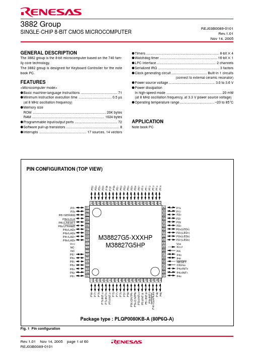
3882 GroupSINGLE-CHIP 8-BIT CMOS MICROCOMPUTER REJ03B0089-0101Rev.1.01Nov 14, 2005元器件交易网V CC , V SS PIN DESCRIPTIONFunctionsNamePin •Apply voltage of 3.3 V ±10 % to Vcc, and 0 V to Vss.•Connected to V SS .•Reset input pin for active “L ”.•Input and output pins for the clock generating circuit.•Connect a ceramic resonator between the X IN and X OUT pins to set the oscillation frequency.•When an external clock is used, connect the clock source to the X IN pin and leave the X OUT pin open.•8-bit I/O port.•I/O direction register allows each pin to be individually programmed as either input or output.•CMOS compatible input level.•CMOS 3-state output structure or N-channel open-drain output structure.•8-bit I/O port.•I/O direction register allows each pin to be individually programmed as either input or output.•CMOS compatible input level.•CMOS 3-state output structure or N-channel open-drain output structure.•8-bit I/O port.•I/O direction register allows each pin to be individually programmed as either input or output.•CMOS compatible input level.•CMOS 3-state output structure.•P24 to P27 (4 bits) are enabled to output large current for LED drive.•8-bit I/O port.•I/O direction register allows each pin to be individually programmed as either input or output.•CMOS compatible input level.•CMOS 3-state output structure.•These pins function as key-on wake-up .•These pins are enabled to control pull-up.Power source Table 1 Pin description (1)Function except a port functionReset input Clock input I/O port P0I/O port P1I/O port P2I/O port P3RESET X IN CNV SS input X OUTClock outputP00–P07•Key-on wake-up input pinsCNV SS P10–P17P20–P27P30–P37FunctionsNamePin P40P41•8-bit I/O port with the same function as port P0<Input level>CMOS compatible input level<Output level>P40, P41 :CMOS 3-state output structureP42-P47 :CMOS 3-state output structure or N-channel open-drain output structure •Each pin level of P42 to P46 can be read even in output port mode.Function except a port functionTable 2 Pin description (2)•8-bit I/O port with the same function as port P0•CMOS compatible input level •CMOS 3-state output structure•8-bit I/O port with the same function as port P0•CMOS compatible input level.•CMOS 3-state output structure.•8-bit CMOS I/O port with the same function as port P0<Input level>P70–P75 :CMOS compatible input level orTTL compatible input level P76, P77 :CMOS compatible input level <Output structure>N-channel open-drain output structure•Each pin level of P70 to P75 can be read even in output port mode.•8-bit CMOS I/O port with the same function as port P0•CMOS compatible input level.•CMOS 3-state output structure.I/O port P4P42/INT 0P43/INT 1P44P45P46•Interrupt input pinsP47/CLKRUN •Serialized IRQ function pin P56P57P50/INT 5P51/INT 20P52/INT 30P53/INT 40P54/CNTR 0P55/CNTR 1I/O port P5•Interrupt input pins •Timer X, timer Y function pins P60–P67P70P71P72P76P77I/O port P6I/O port P7•Interrupt input pins•LPC interface function pins P73/INT 21P74/INT 31P75/INT 41I/O port P8P80/LAD 0P81/LAD 1P82/LAD 2P83/LAD 3P84/LFRAME P85/LRESET P86/LCLK P87/SERIRQ•Serialized IRQ function pinFUNCTIONAL DESCRIPTIONCENTRAL PROCESSING UNIT (CPU)The 3882 group uses the standard 740 Family instruction set. Re-fer to the table of 740 Family addressing modes and machine instructions or the 740 Family Software Manual for details on the instruction set.Machine-resident 740 Family instructions are as follows:The FST and SLW instructions cannot be used.The STP , WIT, MUL, and DIV instructions can be used.[Accumulator (A)]The accumulator is an 8-bit register. Data operations such as data transfer, etc., are executed mainly through the accumulator.[Index Register X (X)]The index register X is an 8-bit register. In the index addressing modes, the value of the OPERAND is added to the contents of register X and specifies the real address.[Index Register Y (Y)]The index register Y is an 8-bit register. In partial instruction, the value of the OPERAND is added to the contents of register Y and specifies the real address.Fig. 5 740 Family CPU register structure[Stack Pointer (S)]The stack pointer is an 8-bit register used during subroutine calls and interrupts. This register indicates start address of stored area (stack) for storing registers during subroutine calls and interrupts.The low-order 8 bits of the stack address are determined by the contents of the stack pointer. The high-order 8 bits of the stack ad-dress are determined by the stack page selection bit. If the stack page selection bit is “0” , the high-order 8 bits becomes “0016”. If the stack page selection bit is “1”, the high-order 8 bits becomes “0116”.The operations of pushing register contents onto the stack and popping them from the stack are shown in Figure 7.Store registers other than those described in Figure 7 with pro-gram when the user needs them during interrupts or subroutine calls.[Program Counter (PC)]The program counter is a 16-bit counter consisting of two 8-bit registers PC H and PC L . It is used to indicate the address of the next instruction to be executed.AAccumulator b7b7b7b7b0b7b15b0b7b0b0b0b0XIndex register X YIndex register Y SStack pointer PC LProgram counter PC HN V T B D I Z CProcessor status register (PS)Carry flag Zero flagInterrupt disable flag Decimal mode flag Break flagIndex X mode flag Overflow flag Negative flag[Processor status register (PS)]The processor status register is an 8-bit register consisting of 5 flags which indicate the status of the processor after an arithmetic operation and 3 flags which decide MCU operation. Branch opera-tions can be performed by testing the Carry (C) flag , Zero (Z) flag, Overflow (V) flag, or the Negative (N) flag. In decimal mode, the Z, V, N flags are not valid.•Bit 0: Carry flag (C)The C flag contains a carry or borrow generated by the arithmetic logic unit (ALU) immediately after an arithmetic operation. It can also be changed by a shift or rotate instruction.•Bit 1: Zero flag (Z)The Z flag is set if the result of an immediate arithmetic operation or a data transfer is “0”, and cleared if the result is anything other than “0”.•Bit 2: Interrupt disable flag (I)The I flag disables all interrupts except for the interrupt generated by the BRK instruction.Interrupts are disabled when the I flag is “1”.•Bit 3: Decimal mode flag (D)The D flag determines whether additions and subtractions are executed in binary or decimal. Binary arithmetic is executed when this flag is “0”; decimal arithmetic is executed when it is “1”.Decimal correction is automatic in decimal mode. Only the ADC •Bit 4: Break flag (B)The B flag is used to indicate that the current interrupt was generated by the BRK instruction. The BRK flag in the processor status register is always “0”. When the BRK instruction is used to generate an interrupt, the processor status register is pushed onto the stack with the break flag set to “1”.•Bit 5: Index X mode flag (T)When the T flag is “0”, arithmetic operations are performed between accumulator and memory. When the T flag is “1”, direct arithmetic operations and direct data transfers are enabled between memory locations.•Bit 6: Overflow flag (V)The V flag is used during the addition or subtraction of one byte of signed data. It is set if the result exceeds +127 to -128. When the BIT instruction is executed, bit 6 of the memory location operated on by the BIT instruction is stored in the overflow flag.•Bit 7: Negative flag (N)The N flag is set if the result of an arithmetic operation or data transfer is negative. When the BIT instruction is executed, bit 7 of the memory location operated on by the BIT instruction is stored in the negative flag.Table 5 Set and clear instructions of each bit of processor status registerSet instruction Clear instruction C flagSECCLCZ flag––I flagSEICLID flagSEDCLDB flag––T flagSETCLTV flag–CLVN flag––Pin Name Input/OutputI/O Structure Non-Port Function Ref.No.Table 6 I/O port function (1)Related SFRs I/O PORTSAll I/O pins are programmable as input or output. All I/O ports have direction registers which specify the data direction of each pin like input/output. One bit in a direction register corresponds to one pin. Each pin can be set to be input or output port.Writing “0” to the bit corresponding to the pin, that pin becomes an input mode. Writing “1” to the bit, that pin becomes an output mode.When the data is read from the bit of the port register correspond-ing to the pin which is set to output, the value shows the port latch data, not the input level of the pin. When a pin set to input, the pin comes floating. In input port mode, writing the port register changes only the data of the port latch and the pin remains high impedance state.When the P8 function selection bit of the port control register 2 is set to “1”, reading from address 001016 reads the port P4 register,and reading from address 001116 reads the port P7 register.Especially, the input level of P42 to P46 pins and P70 to P75 pins can be read regardless of the data of the direction registers in this case.P00-P07P10-P17P20-P27Port P0Port P1CMOS compatible input levelCMOS 3-state output or N-channel open-drain outputPort control register 1(1)(2)P30-P37P40P41Port P2CMOS compatible input levelCMOS 3-state outputPort control register 1Key-on wake up input P42/INT 0P43/INT 1Port P3P44P45P46Input/output,individual bitsInterrupt edge selection registerPort control register 2Port control register 2External interrupt inputP47/CLKRUNPort P4CMOS compatible input levelCMOS 3-state output or N-channel open-drain outputSerialized IRQ control registerSerialized IRQ function output(3)(4)(6)(7)(5)Notes1:For details usage of double-function ports as function I/O ports, refer to the applicable sections.2:Make sure that the input level of each pin should be either 0 V or V CC in STP mode.When an input level is at an intermediate voltage level, the I CC current will become large because of the input buffer gate.Pin NameInput/OutputI/O Format Non-Port FunctionRef.No.Table 7 I/O port function (2)Related SFRs P50/INT 5Port P5Port P6Port P7Port P8Input/output,individual bitsCMOS compatible input levelCMOS 3-state output or N-channel opendrain outputCMOS compatible input levelCMOS 3-state outputCMOS compatible input level or TTL input level Pure N-channel open-drain output CMOS compatible input levelPure N-channel open-drain outputCMOS compatible input levelCMOS 3-state outputExternal interrupt inputInterrupt edge selection registerPort control register 2Port control register 3P51/INT 20P52/INT 30P53/INT 40P54/CNTR 0P55/CNTR 1Timer X, timer Y func-tion I/OTimer XY mode registerP56P57P60–P67P70P71P72Port control register 2P73/INT 21P74/INT 31P75/INT 41External interrupt inputInterrupt edge selection registerPort control register 2P76P77Data bus buffer control registerPort control register 2P80/LAD 0P81/LAD 1P82/LAD 2P83/LAD 3P84/LFRAME P85/LRESET P86/LCLK P87/SERIRQLPC interface function I/OSerialized IRQ function I/O(13)(16)(8)(10)(9)(10)(11)(12)(14)(15)INTERRUPTSInterrupts occur by 14 sources among 17 sources: ten external, six internal, and one software.Interrupt ControlEach interrupt is controlled by an interrupt request bit, an interrupt enable bit, and the interrupt disable flag except for the software in-terrupt caused by the BRK instruction. An interrupt occurs when both the corresponding interrupt request bit and interrupt enable bit are “1” and the interrupt disable flag is “0”.Interrupt enable bits can be set or cleared by software.Interrupt request bits can be cleared by software, but cannot be set by software.The BRK instruction interrupt cannot be disabled with any flag or bit. The I (interrupt disable) flag disables all interrupts except the BRK instruction interrupt.When several interrupts occur at the same time, the interrupts are serviced according to the priority.Interrupt OperationBy acceptance of an interrupt, the following operations are auto-matically performed:1. The contents of the program counter and the processor statusregister are automatically pushed onto the stack.2. The interrupt disable flag is set and the corresponding interruptrequest bit is cleared.3. The interrupt jump destination address is read from the vectortable and stored into the program counter.Interrupt Source SelectionAny of the following interrupt sources can be selected by the inter-rupt source selection register (INTSEL).1. INT0 or Input buffer full2. INT1 or Output buffer empty3. Timer 2 or INT54. CNTR0 or INT05. CNTR1 or INT1External Interrupt Pin SelectionThe external interrupt sources of INT2, INT3, and INT4 can be se-lected from either input pin from INT20, INT30, INT40 or input pin from INT21, INT31, INT41 by the INT2, INT3, INT4 interrupt switch bit (bit 4 of PCTL2).s NotesWhen setting the followings, the interrupt request bit may be set to “1”.•When setting external interrupt active edgeRelated register: Interrupt edge selection register (address003A16); Timer XY mode register (address002316)•When switching interrupt sources of an interrupt vector address where two or more interrupt sources are allocatedRelated register: Interrupt source selection register (address003916)•When setting input pin of external interrupts INT2, INT3 and INT4 Related register: INT2, INT3, INT4 interrupt switch bit of P ort con-trol register 2 (bit 4 of address 002F16)When not requiring the interrupt occurrence synchronized with these setting, take the following sequence.(1)Set the corresponding interrupt enable bit to “0” (disabled).(2)Set the active edge selection bit or the interrupt source selection bit to “1”.(3)Set the corresponding interrupt request bit to “0” after 1 ormore instructions have been executed.(4)Set the corresponding interrupt enable bit to “1” (enabled).Interrupt RequestGenerating Conditions RemarksInterrupt Source Reset (Note 2)INT 0Input buffer full (IBF)INT 1Output buffer empty (OBE)Timer X Timer Y Timer 1Timer 2INT 5CNTR 0INT 0CNTR 1INT 1INT 2INT 3INT 4Key-on wake-up BRK instructionLow HighFFFD 16FFFB 16FFF916FFF716FFF316FFF116FFEF 16FFED 16FFEB 16Priority 123456789101112131415Table 8 Interrupt vector addresses and priority Vector Addresses (Note 1)At resetAt detection of either rising or falling edge of INT 0 inputAt input data bus buffer writing At detection of either rising or falling edge of INT 1 inputAt output data bus buffer read-ingAt timer X underflow At timer Y underflow At timer 1 underflow At timer 2 underflowAt detection of either rising or falling edge of INT 5 inputAt detection of either rising or falling edge of CNTR 0 input At detection of either rising or falling edge of INT 0 inputAt detection of either rising or falling edge of CNTR 1 input At detection of either rising or falling edge of INT 1 input At detection of either rising or falling edge of INT 2 input At detection of either rising or falling edge of INT 3 input At detection of either rising or falling edge of INT 4 inputAt falling of port P3 (at input)input logical level AND At BRK instruction executionNon-maskableExternal interrupt(active edge selectable)External interrupt(active edge selectable)External interruptSTP release timer underflow External interrupt(active edge selectable)External interrupt(active edge selectable)External interrupt(active edge selectable)External interrupt(active edge selectable)External interrupt (falling valid)External interrupt(active edge selectable)External interrupt(active edge selectable)External interrupt(active edge selectable)External interrupt (falling valid)Non-maskable software interrupt At falling edge of LRESET input Notes 1: Vector addresses contain interrupt jump destination addresses.2: Reset functions in the same way as an interrupt with the highest priority.FFFC 16FFFA 16FFF816FFF616FFF216FFF016FFEE 16FFEC 16FFEA 16FFE816FFE416FFE216FFE016FFDE 16FFDC 16LRESET FFE516FFE916FFE316FFE116FFDF 16FFDD 16[LPC Control Register (LPCCON)] 002A16• SYNC output select bit (SYNCSEL)“00”: OK“01”: LONG & OK“10”: Err“11”: LONG & Err• LPC interface software reset bit (LPCSR)“0”: Reset release (automatic)“1”: Reset• LPC interface enable bit (LPCBEN)“0”: P80–P86 works as port“1”: P80–P86 works as LPC interface• Data bus buffer 0 enable bit (DBBEN0)“0”: Data bus buffer 0 disable“1”: Data bus buffer 0 enable• Data bus buffer 1 enable bit (DBBEN1)“0”: Data bus buffer 1 disable“1”: Data bus buffer 1 enableBits 0 and 1 of the LPC control register (LPCCON) specify the SYNC code output.Bit 2 of the LPC control register (LPCCON) enables the LPC inter-face to enter the reset state by software. When LPCSR is set to “1”, LPC interface is initialized in the same manner as the external “L” input to LRESET pin (See Figure 30). Writing “0” to LPCSR the reset state will be released after 1.5 cycle of φ and this bit is cleared to “0”.[Data Bus Buffer Status Register i (i = 0, 1) (DBBSTS0, DBBSTS1)] 002916, 002C16Bits 0, 1 and 3 are read-only bits and indicate the status of the data bus buffer. Bits 2, 4, 5, 6 and 7 are user definable flags which can be read and written by software. The data bus buffer status register can be read out by the host controller when bit 2 of the slave address (A2) is “1”.•Bit 0: Output buffer full flag i (OBFi)This bit is set to “1” when a data is written into the output data bus buffer i and cleared to “0” when the host controller reads out the data from the output data bus buffer i.•Bit 1: Input buffer full flag i (IBFi)This bit is set to “1” when a data is written into the input data bus buffer i by the host controller, and cleared to “0” when the data is read out from the input data bus buffer i by the internal CPU.•Bit 3: XA2 flag (XA2i)The bit 2 of slave address is latched while a data is written into the input data bus buffer i.[Input Data Bus Buffer i(i=0,1)(DBBIN0, DBBIN1)] 002816, 002B16In I/O write cycle from the host controller, the data byte of the data phase is latched to DBBINi (i=0,1). The data of DBBINi can be read out form the data bus buffer registers (DBB0, DBB1) address in SFR area.[Output Data Bus Buffer i (i = 0, 1) (DBBOUT0, DBBOUT1)] 002816, 002B16Writing data to data bus buffer registers (DBB0 , DBB1) address from the internal CPU means writing to DBBOUTi (i = 0, 1). The data of DBBOUTi (i = 1, 0) is read out from the host controller when bit 2 of slave address (A2) is “0”.[LPCi address register H/L(LPC0ADL, LPC1ADL / LPC0ADH, LPC1ADH)] 0FF016 to 0FF316The slave addresses of data bus buffer channel i(i=0,1) are defin-able by setting LPCi address registers H/L (LPC0ADL, LPC0ADH, LPC1ADL, LPC1ADH ). These registers can be set and cleared any time. When the internal CPU reads LPCi address register L, the bit 2 (A2) is fixed to “0”. The bit 2 of slave address (A2) is latched to XA2i flag when the host controller writes the data. The slave addresses, set in these registers, is used for comparing with the addresses from the host controller.Basic Operation of LPC InterfaceSet up steps for LPC interface is as below.•Set the LPC interface enable bit (bit3 of LPCCON) to “1”.•Choose which data bus buffer channel use.•Set the data bus buffer i enable bit (i = 0, 1) (bit 4 or 5 of LPCCON) to “1”.•Set the slave address to LPCi address register L and H (i = 0, 1) (LPC0ADL, LPC0ADH, LPC1ADL, LPC1ADH).(1) Example of I/O write cycleThe I/O write cycle timing is shown in Figure 28. The standard transfer cycle number of I/O write cycle is 13. The communication starts from the falling edge of LFRAME.The data on LAD [3:0] is monitored at every rising edge of LCLK.• 1st clock: The last clock when LFRAME is “Low”. The host send “00002” on LAD [3:0] for communication start.• 2nd clock: LFRAME is “High”. The host send “001X2” on LAD [3:0] to inform the cycle type as I/O write.• From 3rd clock to 6th clock : In these four cycles , the host sends 16-bit slave address. The 3882 compares it with the LPCi ad-dress register H and L (i = 0, 1).3rd clock: The slave address bit [15:12].4th clock: The slave address bit [11:8].5th clock: The slave address bit [7:4].6th clock: The slave address bit [3:0].• 7th clock and 8th clock are used for one data byte transfer. The data is written to the input data bus buffer (DBBINi, i = 0, 1) 7th clock: The host sends the data bit [3:0].8th clock: The host sends the data bit [7:4].• 9th clock and 10th clock are for turning the communication direc-tion from the host→the peripheral to the slave→the host.9th clock: The host outputs “11112” on LAD [3:0].10th clock: The LAD [3:0] is set to tri-state by the host toturn the communication direction.• 11th clock: The 3882 outputs “00002” (SYNC OK) to LAD [3:0] for acknowledgment.• 12th clock: The 3882 outputs “11112” to LAD [3:0]. In this timing the address bit 2 is latched to XA2i (bit3 of DBBSTSi),IBFi (bit 1 of DBBSTSi) is set to “1” and IBF interruptsignal is generated.• 13th clock: The LAD [3:0] is set to tri-state by the host to turn the communication direction.(2) Example for I/O read cycleThe I/O read cycle timing is shown in Figure 29. The standard transfer cycle number of I/O read cycle is 13. The data on LAD [3:0] is monitored at every rising edge of LCLK. The communica-tion starts from the falling edge of LFRAME.•1st clock: The last clock when LFRAME is “Low”. The host sends “00002” on LAD [3:0] for communication start.•2nd clock: LFRAME is “High”. The host sends “000X2” on LAD [3:0] to inform the cycle type as I/O read.• From 3rd clock to 6th clock: In these four cycles , the host sends 16-bit slave address. The 3882 compares it with the LPCi ad-dress register H or L (i = 0, 1).3rd clock: The slave address bit [15:12].4th clock: The slave address bit [11:8].5th clock: The slave address bit [7:4].6th clock: The slave address bit [3:0].• 7th clock and 8th clock are used for turning the communication di-rection from the host→the peripheral to the peripheral→the host.7th clock: The host outputs “11112” on LAD [3:0].8th clock: The LAD [3:0] is set to tri-state by the host toturn the communication direction.• 9th clock: The 3882 outputs “00002” (SYNC OK) to LAD [3:0] for acknowledgment.• 10th clock and 11th clock are used for one data byte transfer from the output data bus buffer i (DBBOUTi) or data bus buffer status register i (DBBSTSi).10th clock: The 3882 sends the data bit [3:0].11th clock: The 3882 sends the data bit [7:4].• 12th clock: The 3882 outputs “11112” to LAD [3:0]. In this timing OBFi (bit 2 of DBBSTSi) is cleared to “0” and OBEinterrupt signal is generated.• 13th clock: The LAD [3:0] is set to tri-state by the host to turn the communication direction.SERIALIZED INTERRUPTThe serialized IRQ circuit communicates the interrupt status to the host controller based on the Serialized IRQ Support for PCI System, Version 6.0.Table 11 shows the summary of serialized interrupt of 3882.ItemThe factors of serialized IRQ The number of frameOperation clockClock restartClock stop inhibitionFunctionThe numbers of serialized IRQ factor that can output simultaneously are 3.• Channel 0 (IRQ1,IRQ2)➀ Setting Software IRQi (i = 1, 12) request bit (bits 0, 1 of SERIRQ) to “1”.➁ The “1” of OBF0 and Hardware IRQi ( i=1, 12) request bit (bits 3, 4 of SERCON) to “1”.• Channel 1 (IRQx ; user selectable)➀ Setting the IRQx request bit (bit 7 of SERIRQ) to “1”.➁ The “1” of OBF1 and Hardware IRQx request bit to “1”.• Channel 0 (IRQ1, IRQ12)➀ Setting Software IRQ1 request bit (bit 0 of SERIRQ) to “1” or detecting “1” of OBF0 with “1” of Hardware IRQ1 request bit (bit 4 of SERCON) selects IRQ1 Frame .➁ Setting IRQ12 Software request bit (bit 1 of SERIRQ) to “1” or detecting “1” of OBF0 with “1” of Hardware IRQ1 request bit (bit 4 of SERCON) selects IRQ12 Frame.• Channel 1 (IRQx ; user selectable)Setting IRQx frame select bit (bit 2-6 of SERIRQ) selects IRQ 1–15 frame or extend frame 0–10.Synchronized with LCLK (Max. 33 MHz).LPC clock restart enable bit (bit 1 of SERCON) enables restart owing to “L” output of CLKRUN with the interrupt when the LPC clock has stopped or slowed down.LPC clock stop inhibition bit (bit 2 of SERCON) enables the inhibition of clock stop control during the IRQSER cycle when the clock tends to stop or slow down.Table 11 Smmary of serialized IRQ functionNOTES ON PROGRAMMINGProcessor Status RegisterThe contents of the processor status register (PS) after a reset are undefined, except for the interrupt disable flag (I) which is “1”. Af-ter a reset, initialize flags which affect program execution. In particular, it is essential to initialize the index X mode (T) and the decimal mode (D) flags because of their effect on calculations.InterruptsThe contents of the interrupt request bits do not change immedi-ately after they have been written. After writing to an interrupt request register, execute at least one instruction before perform-ing a BBC or BBS instruction.Decimal Calculations•To calculate in decimal notation, set the decimal mode flag (D) to “1”, then execute an ADC or SBC instruction. After executing an ADC or SBC instruction, execute at least one instruction be-fore executing a SEC, CLC, or CLD instruction.•In decimal mode, the values of the negative (N), overflow (V), and zero (Z) flags are invalid.TimersIf a value n (between 0 and 255) is written to a timer latch, the fre-quency division ratio is 1/(n+1).Multiplication and Division Instructions•The index X mode (T) and the decimal mode (D) flags do not af-fect the MUL and DIV instruction.•The execution of these instructions does not change the con-tents of the processor status register.PortsThe contents of the port direction registers cannot be read. The following cannot be used:•The data transfer instruction (LDA, etc.)•The operation instruction when the index X mode flag (T) is “1”•The instruction with the addressing mode which uses the value of a direction register as an index•The bit-test instruction (BBC or BBS, etc.) to a direction register •The read-modify-write instructions (ROR, CLB, or SEB, etc.) to a direction register.Use instructions such as LDM and STA, etc., to set the port direc-tion registers.Instruction Execution TimeThe instruction execution time is obtained by multiplying the pe-riod of the internal clock φ by the number of cycles needed to execute an instruction.The number of cycles required to execute an instruction is shown in the list of machine instructions.The period of the internal clock φ is twice of the X IN period in high-speed mode.Reserved Area, Reserved BitDo not write any data to the reserved area in the SFR area and thespecial page. (Do not change the contents after reset.)CPU Mode RegisterBe sure to fix bit 3 of the CPU mode register (address 003B16) to “1”.。
9_classes
Classes
The notion of a “valid Date” is an important special case of the idea of a valid value We try to design our types so that values are guaranteed to be valid
If so, use a struct Try hard to think of good invariants for your classes
that saves you from poor buggy code
Stroustrup/Programming 13
Classes
Date:
A class is a (user-defined) type that specifies how objects of its type can be created and used In C++ (as in most modern languages), a class is the key building block for large programs
Enumerations Operator overloading
Stroustrup/Programming
3
Classes
The idea:
Hale Waihona Puke A class directly represents a concept in a program
If you can think of “it” as a separate entity, it is plausible that it could be a class or an object of a class Examples: vector, matrix, input stream, string, FFT, valve controller, robot arm, device driver, picture on screen, dialog box, graph, window, temperature reading, clock
1.增长动力与政策工具排序(陆磊)

结论:
三、准备金优于加息优于汇率改革
准备金上调仍有空间
储备充足:超额准备金率为3.13%。其中,四大国 有商业银行为1.72%,股份制商业银行为3.13%,农 村信用社为8.78%。 为金融不稳定作准备:准备金在经济下行或金融危 机时期是最干净的资产。 可以替代加息
― ―
2006.07 2006.10 2007.01 2007.04 2007.07 2007.10 2008.01 2008.04 2008.07 2008.10 2009.01 2009.04 2009.07 2009.10
4
-20
0
பைடு நூலகம்
-40
-4
-60
-8
32
四、流动性过剩将得到遏制
地方融资平台是否严重问题?
27
三、准备金优于加息优于汇率改革
汇率升值的实体经济压力最大时期:2009年7-9月;当 前的压力是中美政治博弈,实体经济压力在下降
28
三、准备金优于加息优于汇率改革
当前的确是汇率动议的敏感期——中日比较
29
四、流动性过剩将得到遏制
恰如我们所预言:M1增速峰值在1月已现
30
四、流动性过剩将得到遏制
7
一、增长动力呈下降趋势
外需是第一要务——出口增长但顺差收缩
8
一、增长动力呈下降趋势
投资:确定性减速
9
一、增长动力呈下降趋势
消费增长:无法超预期
10
二、供给冲击:塑造全年的增长和通胀
构成CPI上涨的主因仍然是食品
11
金融脱媒与小企业融资ppt课件

20
07
07
年
9月
月
月
月
月
月
月
月
月
月
月
月
月
月
月
月
月
1.0000
2006年1月4日 2006年2月4日 2006年3月4日 2006年4月4日 2006年5月4日 2006年6月4日 2006年7月4日 2006年8月4日 2006年9月4日 2006年10月4日 2006年11月4日 2006年12月4日 2007年1月4日 2007年2月4日 2007年3月4日 2007年4月4日 2007年5月4日 2007年6月4日 2007年7月4日 2007年8月4日 2007年9月4日
2.0000
3.0000
4.0000
5.0000
6.0000
7.0000
回购加权平均收益率 1年期存款利率 1年期贷款利率
各类利率的走势
脱媒的表现(4):利率政策的效果不确定
/sundae_meng
3个月SHIBOR 1年SHIBOR 2年期国债收益率
10
15
第六届中小企业融资论坛
金融“脱媒” 与小企业融资
/sundae_meng
发展直接融资是我国金融发展的重大战略
传统的中国金融体系以银行间接融资为主导。这种金 融结构存在着诸如风险集中、定价非市场化、难以有 效沟通储蓄与投资、难以为企业发展提供资本金等大 量问题。 因此,多渠道发展直接融资,是我国金融体制改革的 一项战略目标。 胡锦涛主席在中共17大政治报告中重申:在今后的金 融改革中,应“发展各类金融市场……优化资本市场 结构,多渠道提高直接融资比重”。这就从战略层面 确定了我国今后金融改革和金融发展的基本战略目标。
宏观经济体系-申万
申万研究
6
1.5 宏观研究团队
杨成长:首席经济学家 李慧勇:首席宏观分析师 苏畅、贺振华、刘莹、孟祥娟 专家团队:相关领域专家
申万研究
7
主要内容
1. 宏观研究体系介绍 2. 最重要的三组指标 3. 4. 基本的分析方法 对未来经济的看法
申万研究
20
2.1.2 就业
失业率
新增就业人口
申万研究
21
2.1.3 价格
中国价格指数的种类 生产者价格:工业品出厂价格指数、原材料燃料动力购进价格指数 消费者价格:居民消费价格指数、商品零售价格指数 居民消费价格指数:通货膨胀的核心指标 按照商品的用途分为八类:食品(33.3%)、烟酒及用品(9.2%)、衣着 (9.5%)、家庭设备(7.7%)、医疗保健以及个人用品(6.6%)、交通和 通信(8.5%)、娱乐教育文化用品及服务(13.2%)、居住(12%)、 城市居民消费价格指数、农村居民消费价格指数
申万研究
16
2.1.1 经济增长-消费
反映消费需求的主要指标
总量指标: 社会消费品零售总额 最终消费 区别:
结构指标: 城市和县以下社会消费品零售总额 城镇居民消费性支出和农村居民生活消费支出 城镇居民最终消费和农村居民最终消费 政府消费和居民消费
申万研究 17
0 5 10 15 20 25 30 35 40
消费意愿下降以及其他资产收益率下降,导致居 民储蓄存款增速创10年来新高
储蓄增加额 同比增长率(右轴)
申万研究 33
2.3.2 利率
Feb-89
同比%
利率决定理论
Feb-90 Feb-91 Feb-92 Feb-93 Feb-94 Feb-95 Feb-96 Feb-97 Feb-98 Feb-99 Feb-00 Feb-01 Feb-02 Feb-03 Feb-04 Feb-05 F Mar-08 Sep-07 Mar-07 Sep-06 Mar-06 Sep-05 Mar-05 Sep-04 Mar-04 Sep-03 Mar-03 Sep-02 Mar-02 Sep-01 Mar-01 Sep-00 Mar-00 Sep-99 Mar-99 Sep-98 Mar-98 Sep-97 %
OPM1 Assignment 运营管理
Task SheetIssue Date Wed 5th Nov. Submission Deadline Mon 8th Dec. Format This is an individual assignment. Submission is via Studentcentral, only.The Task Select ONE of the three operations listed below and use your own initiative and imagination to develop a process map of the main activities, which you think wouldbe directly involved in the provision of the service to customers.∙The ordering, re-supply and merchandising/display of fresh fruit and vegetables, by a supermarket or other sizeable greengrocer.∙The routine servicing and/or repair of vehicles, by an independent garage or main car dealership.∙The collection and delivery of letters and packages, by a document and parcel delivery/logistics company.Then, choose one of the sub-processes or activities within the process anddevelop a lower level (i.e. more detailed) map of that stage.Finally, position your chosen operation on a ‘4Vs’ diagram, and use termssuggested by Slack and others to classify its type and likely layout characteristics.Provide a concise, written rationale for this analysis (max. 400 words).Notes Use the drawing facilities in Powerpoint or Word to prepare your process map(s).Do not use Visio, SmartDraw or any other diagramming software.You should identify all of the main inputs, outputs, guides and enablers (IOGEs)involved in the process, and you should also make appropriate use of some of themain BPMN symbols in your detailed map.You are not required to provide a written description of your process, although youmay annotate your diagrams (very briefly) in a few places if you think this will helpthe reader to understand how the process works.References All sources should be referenced using the Harvard system.Weighting This assignment represents one half of the assessment within the O&PM strand of the module. It therefore counts towards 25% of the overall mark for the module. Criteria You will be assessed primarily on your ability to apply the process mapping techniques and operations typology analysis, that were covered during the first fewweeks of the module. However, some marks will be reserved for the plausibility ofthe work-flow (and any other flows) depicted in the process diagram(s), and for thequality of presentation.Guidance The learning materials relating to the first block of teaching sessions (i.e. up to Reading Week) cover most of the learning required to undertake this assignment,although you may find that some background research could prove useful. Youshould contact your seminar tutor for clarification of any specific queries about thetask. Please note, however, that tutors will be less forthcoming in their guidancein the final week or so before the hand-in deadline.Assessment Criteria ChecklistProcess Mapping (67% of marks)∙Core process mapped?∙Recognised mapping approach used?∙Process broken down into appropriate transformation stages?∙Unambiguous, value-adding workflow/transformation steps?∙Clearly defined primary flows (inputs/outputs)?∙Clearly defined branching and merging points/logic (where appropriate)?∙Appropriate inclusion of supporting information/document flows?∙Main enablers (transforming resources) & guides (business rules) identified?∙Appropriate use of swim lanes?∙Correct use of BPMN symbols?∙Process appropriately mapped at more than one level of detail?∙Plausible process structure and workflow sequencing?(n.b. Detailed knowledge of a real process is neither expected, nor required.)∙Inclusion of other elements?(e.g. Process control points; Feedback loops; Linkages with other processes)‘4Vs’ Diagram, Operations Typology & Layout Characteristics (33% of marks)∙Process/sub-processes properly categorised?∙Credible ‘4Vs’ plot/diagram?∙Likely layout characteristics described?∙Coherent rationale/justification for the operations and layout analyses and conclusions?Learning Outcomes Being AssessedSubject Specific:∙Demonstrate the ability to recognise and map business processes, and to understand the role of operations management and IS/IT in the ongoing challenge of achieving customer satisfaction, competitive advantage and profitability.Cognitive:∙Apply a range of qualitative and quantitative techniques in the analysis and evaluation of common problems within the core, value adding functions of a business.∙Demonstrate the ability to think critically about a subject, and the ability to interpret quantitative data and qualitative information in context, in order to support business planning and decision processes.∙Work in a planned and effective way on projects, the nature of which may be new and which require initiative and creativity in how they are tackled.。
基于SEER数据库老年肺鳞癌患者的预后分析
作者简介:衡晨,女,在读硕士研究生,主要从事人群健康及疾病预后的预测模型构建方面的研究㊂ ә 通信作者,E -m a i l :y i j i n ga @s i n a .c o m ㊂㊃论 著㊃D O I :10.3969/j.i s s n .1672-9455.2024.08.018基于S E E R 数据库老年肺鳞癌患者的预后分析衡 晨,李 娆,易 静ә重庆医科大学公共卫生学院医学与社会发展研究中心/健康领域社会风险预测治理协同创新中心,重庆400016 摘 要:目的 基于S E E R 数据库分析影响老年肺鳞癌患者预后的危险因素,并构建预测模型㊂方法 基于S E E R 数据库,选取2004 2015年确诊为肺鳞癌的25602例患者作为研究对象,按照7ʒ3随机分为训练集(17921例)与验证集(7681例);通过K a pl a n -M e i e r 生存曲线分析肺鳞癌患者基本资料与预后的相关性;利用C o x 回归和L A S S O 回归分析确定影响老年肺鳞癌患者预后的独立危险因素并构建列线图模型;以C -i n d e x ㊁受试者工作特征(R O C )曲线㊁决策曲线评估列线图模型的预测性能㊂结果 25602例患者中死亡17717例(69.2%);多因素C o x 回归分析结果显示,年龄越大㊁高T 分期㊁高N 分期㊁高M 分期㊁未接受手术是影响老年肺鳞癌患者预后不良的危险因素(P <0.05);训练集和验证集中用于评估列线图模型的C -i n d e x 分别为0.732(95%C I :0.727~0.736)和0.733(95%C I :0.725~0.739),训练集列线图模型预测半年㊁1年㊁3年肺鳞癌患者预后的曲线的曲线下面积(A U C )分别为0.772(95%C I :0.764~0.779)㊁0.795(95%C I :0.789~0.802)㊁0.846(95%C I :0.839~0.852)㊂验证集列线图模型预测半年㊁1年㊁3年肺鳞癌患者预后的A U C 分别为0.774(95%C I :0.763~0.785)㊁0.805(95%C I :0.795~0.815)㊁0.839(95%C I :0.829~0.850)㊂决策曲线结果显示,列线图模型的临床实用性良好㊂结论 老年肺鳞癌患者年龄㊁T 分期㊁N 分期㊁M 分期㊁手术情况对其预后有显著影响,构建的列线图模型能较为直观㊁准确地预测患者生存率,可为评估老年肺鳞癌患者预后提供科学依据㊂关键词:S E E R 数据库; 列线图; 肺鳞癌; 生存预后; 老年中图法分类号:R 734.2文献标志码:A文章编号:1672-9455(2024)08-1111-07P r o g n o s t i c a n a l y s i s o f e l d e r l y p a t i e n t s w i t h l u n g s qu a m o u s c e l l c a r c i n o m a b a s e d o n S E E R d a t a b a s eH E N G C h e n ,L I R a o ,Y I J i n gәR e s e a r c h C e n t e r f o r M e d i c i n e a n d S o c i a l D e v e l o p m e n t /I n n o v a t i o n C e n t e r fo r S o c i a l R i s k G o v e r n a n c e i n H e a l t h ,S c h o o l o f P u b l i c H e a l t h ,C h o n g q i n gM e d i c a l U n i v e r s i t y ,C h o n g q i n g 400016,C h i n a A b s t r a c t :O b je c t i v e T o a n a l y z e t h e r i s kf a c t o r s f o r t h e p r og n o s i s o f e l d e r l y p a t i e n t s w i th l u n g s q u a m o u s c e l l c a r ci n o m a a n d c o n s t r u c t a p r e d i c t i o n m o d e l b a s e d o n S E E R d a t a b a s e .M e t h o d s B a s e d o n t h e S E E R d a t a -b a s e ,a t o t a l o f 25602p a t i e n t s d i a g n o s e d w i t h l u n g s qu a m o u s c e l l c a r c i n o m a f r o m 2004t o 2015w e r e s e l e c t e d a s t h e r e s e a r c h s u b j e c t s .T h e p a t i e n t s w e r e r a n d o m l y d i v i d e d i n t o t r a i n i n g se t (17921c a s e s )a n d v a l i d a t i o n s e t (7681c a s e s )a c c o r d i n g t o 7ʒ3.K a p l a n -M e i e r s u r v i v a l c u r v e w a s u s e d t o a n a l y z e t h e c o r r e l a t i o n b e t w e e n b a s i c d a t a a n d p r o g n o s i s of p a t i e n t s w i t h l u ng s q u a m o u s c e l l c a r c i n o m a .C o x r e g r e s s i o n a n d L A S S O r e gr e s s i o n a n a l -y s i s w e r e u s e d t o d e t e r m i n e t h e i n d e p e n d e n t r i s k f a c t o r s f o r t h e p r o g n o s i s o f e l d e r l y p a t i e n t s w i t h l u n g s q u a -m o u s c e l l c a r c i n o m a a n d a n o m o g r a m m o d e l w a s c o n s t r u c t e d .T h e p r e d i c t i v e p e r f o r m a n c e o f t h e n o m o gr a m m o d e l w a s e v a l u a t e d b y C -i n d e x ,r e c e i v e r o p e r a t i n g c h a r a c t e r i s t i c (R O C )c u r v e a n d d e c i s i o n c u r v e .R e s u l t s A m o n gt h e 25602p a t i e n t s ,17717(69.2%)d i e d .M u l t i v a r i a t e C o x r e g r e s s i o n a n a l y s i s s h o w e d t h a t o l d e r a g e ,h i gh e r T s t a g e ,h i g h e r N s t a g e ,h i g h e r M s t a g e a n d w i t h o u t s u r g e r y w e r e r i s k f a c t o r s f o r p o o r p r o g n o s i s o f e l d e r l y pa -t i e n t s w i t h l u n g s q u a m o u s c e l l c a r c i n o m a (P <0.05).T h e C -i n d e x u s e d t o e v a l u a t e t h e n o m o gr a m m o d e l i n t h e t r a i n i n g se t a n d t h e v a l i d a t i o n s e t w e r e 0.732(95%C I :0.727-0.736)a n d 0.733(95%C I :0.725-0.739)r e s p e c t i v e l y .T h e a r e a u n d e r t h e c u r v e (A U C )of t h e t r a i n i ng s e t m o d e l f o r p r e d i c t i n g th e p r o g n o si s o f pa t i e n t s w i t h l u n g s qu a m o u s c e l l c a r c i n o m a a t h a l f a y e a r ,o n e y e a r a n d t h r e e y e a r s w a s 0.772(95%C I :0.764-0.779),0.795(95%C I :0.789-0.802)a n d 0.846(95%C I :0.839-0.852)r e s p e c t i v e l y.T h e a r e a u n d e r t h e A U C o f t h e v a l i d a t i o n s e t m o d e l f o r p r e d i c t i n g t h e p r o g n o s i s o f p a t i e n t s w i t h l u n g s qu a m o u s c e l l c a r c i n o m a a t h a l f a y e a r ,o n e y e a r ,a n d t h r e e y e a r s w a s 0.774(95%C I :0.763-0.785),0.805(95%C I :0.795-0.815)a n d0.839(95%C I :0.829-0.850)r e s p e c t i v e l y .T h e d e c i s i o n a n a l y s i s c u r v e s h o w e d t h a t t h e n o m o gr a m m o d e l ㊃1111㊃检验医学与临床2024年4月第21卷第8期 L a b M e d C l i n ,A pr i l 2024,V o l .21,N o .8h a d g o o d c l i n i c a l p r a c t i c a b i l i t y .C o n c l u s i o n T h e a g e ,T s t a g e ,N s t a g e ,M s t a g e a n d o p e r a t i o n s t a t u s h a v e s i g-n i f i c a n t i n f l u e n c e o n t h e p r o g n o s i s o f e l d e r l y p a t i e n t s w i t h l u n g s qu a m o u s c e l l c a r c i n o m a .T h e c o n s t r u c t e d n o -m o g r a m m o d e l c a n i n t u i t i v e l y a n d a c c u r a t e l y pr e d i c t t h e s u r v i v a l r a t e o f p a t i e n t s ,w h i c h c a n p r o v i d e s c i e n t i f i c b a s i s f o r e v a l u a t i o n o f t h e p r o g n o s i s o f e l d e r l y p a t i e n t s w i t h l u n g s qu a m o u s c e l l c a r c i n o m a .K e y wo r d s :S E E R d a t a b a s e ; n o m o g r a m ; l u n g s q u a m o u s c e l l c a r c i n o m a ; s u r v i v a l p r o g n o s i s ; e l d e r l y 肺癌是最常见的恶性肿瘤,占所有恶性肿瘤的11.6%,2018年全球因肺癌死亡的人数超过170万[1]㊂肺癌主要包括非小细胞肺癌和小细胞肺癌,其中非小细胞肺癌占肺癌总数的85%[2]㊂鳞状细胞癌占非小细胞肺癌总数的30%,通常由吸烟引起,在男性群体中更常见,生长缓慢[3]㊂有研究表明,30%~40%的肺癌患者年龄在70岁及以上[4]㊂随着人口老龄化问题越来越突出,开展针对老年群体的肺癌相关研究的需求越发迫切㊂既往研究表明,肺鳞癌患者的总生存率与年龄呈负相关[5]㊂因此,有必要分析老年肺鳞癌患者预后的影响因素,以建立良好的预后预测模型,以期为评估老年肺鳞癌患者的预后提供参考㊂S E E R 数据库是美国癌症患者数据的权威来源,该数据库的样本量大㊁数据类型多㊂深入挖掘其中的信息有助于更好地了解㊁掌握癌症预后的影响因素㊂精确的预后分析在改善患者生活质量方面发挥着至关重要的作用㊂目前有关老年肺鳞癌患者预后分析的研究一般采用C o x 比例风险回归模型或竞争风险模型[6-9],很少有将C o x ㊁L A S S O 回归分析相结合的研究㊂传统的T NM 分期系统存在局限性,如未纳入其他影响预后的变量,而列线图模型直观㊁应用方便,能根据患者的疾病特征评估个体化风险,能纳入疾病的相关影响因素[10],可以为临床医师评估患者预后㊁制订治疗方案提供科学参考㊂本研究旨在分析65岁及以上的老年肺鳞癌患者预后的影响因素,以期为有效改善老年肺鳞癌患者预后提供科学参考㊂现报道如下㊂1 资料与方法1.1 数据来源与研究对象 从S E E R 数据库中提取2004-2015年被诊断为肺鳞癌25602例患者的人口学及临床特征资料,按照7ʒ3随机分为训练集(17921例)与验证集(7681例)㊂纳入标准:(1)诊断时间为2004-2015年;(2)肿瘤原发部位为肺和支气管;(3)病理诊断结果为鳞癌;(4)生存资料完整,且生存时间ȡ1个月;(5)只有1个原发肿瘤;(6)年龄ȡ65岁㊂排除标准:(1)缺乏婚姻状态㊁种族㊁患侧部位㊁临床分期㊁组织学分级㊁手术情况等信息;(2)死亡原因未知㊂两个数据集患者的年龄㊁性别㊁婚姻状态㊁种族㊁原发部位㊁患侧部位㊁T 分期㊁N 分期㊁M 分期㊁组织学分级㊁手术情况比较,差异均无统计学意义(P >0.05),具有可比性㊂见表1㊂1.2 方法 使用S E E R*S t a t 8.4.2软件,选取I n c i -d e n c e -S E E R R e s e a r c h D a t a ㊁17R e gi s t r i e s ㊁N o v 2022S u b (2000-2020)数据集,提取患者基本资料㊂纳入信息包括年龄㊁性别㊁婚姻状态㊁种族㊁原发部位㊁患侧部位㊁T 分期㊁N 分期㊁M 分期㊁组织学分级㊁手术情况㊁生存时间及生存状态㊂生存时间指患者从确诊肺鳞癌之日至该癌症导致死亡的时间㊂1.3 统计学处理 采用S P S S 23.0统计软件进行数据分析处理㊂符合正态分布的计量资料以x ʃs 表示,两组间比较采用独立样本t 检验;不符合正态分布的计量资料以M (P 25,P 75)表示,两组间比较采用M a n n -W h i t -n e y U 检验㊂计数资料以例数或百分率表示,组间比较采用χ2检验㊂采用R S t u d i o 2022.7.0.548软件通过K a pl a n -M e i e r 生存曲线分析肺鳞癌患者基本资料与预后的相关性;采用单因素与多因素C o x 回归分析并结合L A S S O 回归分析影响肺鳞癌患者预后不良的危险因素;构建预后列线图预测模型;采用C -i n d e x ㊁决策曲线和受试者工作特征(R O C )曲线评估模型的预测性能㊂以P <0.05为差异有统计学意义㊂2 结 果2.1 训练集和验证集患者的生存结局 25602例患者中死亡17717例(69.2%)㊂中位生存时间为17.00(5.00,79.00)个月;中位随访时间为76.00(45.00,109.00)个月㊂训练集中有5482例患者存活,12439例患者死亡㊂验证集有2403例患者存活,5278例患者死亡㊂2.2 训练集和验证集患者的基本资料比较 训练集和验证集的基本资料比较,差异均无统计学意义(P >0.05)㊂见表1㊂表1 训练集和验证集患者的基本资料比较[n (%)]数据集n年龄(岁)65~<7070~<7575~<80ȡ80性别男女婚姻状态已婚未婚训练集179214693(26.2)4848(27.1)4403(24.6)3977(22.2)10978(61.3)6943(38.7)9606(53.6)8315(46.4)验证集76812050(26.7)2103(27.4)1842(24.0)1686(22.0)4657(60.6)3024(39.4)4176(54.4)3505(45.6)χ21.6300.8911.269P0.6530.3450.260㊃2111㊃检验医学与临床2024年4月第21卷第8期 L a b M e d C l i n ,A pr i l 2024,V o l .21,N o .8续表1 训练集和验证集患者的基本资料比较[n (%)]数据集n种族白种人黑种人其他种族原发部位肺上叶肺下叶其他部位训练集1792115237(85.0)1705(9.5)979(5.5)9926(55.4)5700(31.8)2295(12.8)验证集76816575(85.6)682(8.9)424(5.5)4245(55.3)2424(31.6)1012(13.2)χ22.5670.686P0.2770.710数据集n患侧部位左侧右侧T 分期T 1T 2T 3T 4训练集179217878(44.0)10043(56.0)3678(20.5)7516(41.9)1789(10.0)4938(27.6)验证集76813324(43.3)4357(56.7)1575(20.5)3246(42.3) 763(9.9)2097(27.3)χ21.0220.271P0.3120.965数据集nN 分期N 0N 1N 2N 3M 分期M 0M 1训练集179219134(51.0)2046(11.4)5477(30.6)1264(7.1)13508(75.4)4413(24.6)验证集76813975(51.8)878(11.4)2284(29.7)544(7.1)5847(76.1)1834(23.9)χ21.8621.629P0.6020.202数据集n组织学分级Ⅰ级Ⅱ级Ⅲ级Ⅳ级手术情况接受手术未接受手术训练集17921563(3.1)7628(42.6)9533(53.2)197(1.1)6784(37.9)11137(62.1)验证集7681248(3.2)3221(41.9)4141(53.9)71(0.9)2958(38.5)4723(61.5)χ22.7220.980P0.4360.3222.3 肺鳞癌患者基本资料与预后的相关性及对预后不良的单因素与多因素C o x 回归分析 将训练集的资料进行单因素C o x 回归分析,结果显示,年龄㊁性别㊁婚姻状态㊁种族㊁原发部位㊁患侧部位㊁T 分期㊁N分期㊁M 分期㊁组织学分级㊁手术情况是肺鳞癌患者预后不良的影响因素(P <0.05)㊂K a p l a n -M e i e r 生存曲线分析结果显示,以上11项变量是肺鳞癌患者预后不良的影响因素(P <0.05),见图1㊂为了避免过度拟合,将这11项变量进行L A S S O 回归和交叉验证,见图2㊁3㊂基于调优系数等于l a m b d a .1s e 筛选出了年龄㊁T 分期㊁N 分期㊁M 分期㊁手术情况5项变量,剔除了性别㊁婚姻状态㊁种族㊁原发部位㊁患侧部位㊁组织学分级6项变量㊂以患者的预后情况作为因变量(存活=0,死亡=1),将筛选出的年龄(65~<70岁=0,70~<75岁=1,75~<80岁=2,ȡ80岁=3)㊁T分期(T 1=0,T 2=1,T 3=2,T 4=3)㊁N 分期(N 0=0,N 1=1,N 2=2,N 3=3)㊁M 分期(M 0=0,M 1=1)㊁手术情况(接受手术=0,未接受手术=1)作为自变量进行多因素C o x 回归分析,结果显示,年龄越大㊁高T 分期㊁高N 分期㊁高M 分期㊁未接受手术是老年肺鳞癌患者预后不良的危险因素(P <0.05)㊂见表2㊂表2 训练集单因素和多因素C o x 回归分析变量单因素分析H R (95%C I )P多因素分析H R (95%C I )P年龄(岁) 65~<70参照参照70~<751.015(0.967~1.066)0.5541.068(1.017~1.121)0.00875~<801.126(1.072~1.184)<0.0011.175(1.118~1.235)<0.001 ȡ801.347(1.281~1.417)<0.0011.292(1.228~1.360)<0.001㊃3111㊃检验医学与临床2024年4月第21卷第8期 L a b M e d C l i n ,A pr i l 2024,V o l .21,N o .8续表2 训练集单因素和多因素C o x 回归分析变量单因素分析H R (95%C I )P多因素分析H R (95%C I )P性别男参照女0.886(0.854~0.918)<0.001婚姻状态已婚参照未婚1.100(1.062~1.140)<0.001种族白种人参照黑种人1.217(1.148~1.290)<0.001 其他种族1.088(1.007~1.174)0.032原发部位肺上叶参照肺下叶1.028(0.988~1.069)0.172其他部位1.464(1.390~1.542)<0.001患侧部位左侧参照右侧1.060(1.023~1.098)0.001T 分期 T 1参照参照T 22.088(1.975~2.208)<0.0011.637(1.546~1.733)<0.001 T 33.192(2.973~3.427)<0.0012.236(2.079~2.405)<0.001 T 44.371(4.125~4.631)<0.0012.174(2.044~2.313)<0.001N 分期 N 0参照参照N 11.537(1.450~1.629)<0.0011.276(1.203~1.353)<0.001 N 22.806(2.695~2.922)<0.0011.458(1.396~1.524)<0.001 N 33.235(3.031~3.453)<0.0011.401(1.308~1.500)<0.001M 分期 M 0参照参照M 13.191(3.069~3.318)<0.0011.865(1.790~1.944)<0.001组织学分级Ⅰ级参照Ⅱ级0.920(0.829~1.021)0.117 Ⅲ级1.076(0.971~1.193)0.164 Ⅳ级1.238(1.022~1.499)0.030手术情况 接受手术参照参照未接受手术4.060(3.892~4.236)<0.0012.552(2.432~2.678)<0.001注:表示无数据㊂㊃4111㊃检验医学与临床2024年4月第21卷第8期 L a b M e d C l i n ,A pr i l 2024,V o l .21,N o .8注:A 为不同年龄肺鳞癌患者的生存曲线;B 为不同性别肺鳞癌患者的生存曲线;C 为不同婚姻状态肺鳞癌患者的生存曲线;D 为不同种族肺鳞癌患者的生存曲线;E 为不同原发部位肺鳞癌患者的生存曲线;F 为不同患侧部位肺鳞癌患者的生存曲线;G 为不同T 分期肺鳞癌患者的生存曲线;H 为不同N 分期肺鳞癌患者的生存曲线;I 为不同M 分期肺鳞癌患者的生存曲线;J 为不同组织学分级肺鳞癌患者的生存曲线;K 为不同手术情况肺鳞癌患者的生存曲线㊂图1不同基本资料肺鳞癌患者的生存曲线图2 预后影响因素的L A S S O 回归分析2.4 列线图模型的建立与验证 基于多因素C o x 回归分析结果,纳入年龄㊁T 分期㊁N 分期㊁M 分期㊁手术情况作为独立预测因子建立列线图模型㊂ 变量评分 代表一个评分尺度,从每个变量的某个取值处对应到 变量评分 即为该变量取值的评分,将患者各个指标的评分相加得到总分,对应到 变量总得分 上寻找对应的分数,作垂线至生存概率轴得到最终结果㊂见图4㊂训练集和验证集中用于评估列线图模型的C -i n d e x 分别为0.732(95%C I :0.727~0.736)和0.733(95%C I :0.725~0.739)㊂训练集列线图模型预测半年㊁1年㊁3年肺鳞癌患者预后的曲线下面积(A U C )分别为0.772(95%C I :0.764~0.779)㊁0.795(95%C I :0.789~0.802)㊁0.846(95%C I :0.839~0.852)㊂验证集列线图模型预测半年㊁1年㊁3年肺鳞癌患者预后的A U C 分别为0.774(95%C I :0.763~0.785)㊁0.805(95%C I :0.795~0.815)㊁0.839(95%C I :0.829~0.850)㊂决策曲线结果见图5㊂图3 L A S S O 回归交叉验证图㊃5111㊃检验医学与临床2024年4月第21卷第8期 L a b M e d C l i n ,A pr i l 2024,V o l .21,N o .8图4 预测老年肺鳞癌患者半年㊁1年㊁3年肺癌特异性生存的列线图模型注:A 为列线图模型的半年决策曲线;B 为列线图模型的1年决策曲线;C 为列线图模型的3年决策曲线㊂图5 列线图模型在不同生存情况中的决策曲线3 讨 论本研究纳入了不同基本资料的老年肺鳞癌患者作为研究对象,其中男性患者占比高于女性患者,这可能是因为男性患者的一些不良习惯更易导致患病㊂由于S E E R 数据库记录的是美国癌症患者数据,故纳入患者中白种人较多㊂在肿瘤特征方面,肿瘤原发部位为肺上叶的患者占比最高,患侧部位位于左侧和右侧的比例则较为均衡㊂纳入病例的T 分期最多为T 2期,N 分期最多为N 0期,M 1期的患者占比不高,组织学分级为Ⅲ级的患者占比最高㊂此外,较少患者接受过手术,这可能是因为手术对于部分老年患者来讲风险较大,故未接受手术㊂根据L A S S O 回归结合C o x 回归分析结果最终确定了5个影响老年肺鳞癌患者预后的因素,其中,年龄更大是影响老年肺鳞癌患者预后不良的危险因素(P <0.05),与既往的研究结果一致[11-12]㊂老年群体身体机能弱㊁细胞衰老㊁合并多种系统慢性疾病都有可能不利于癌症患者的预后[13]㊂本研究结果显示,高T 分期是影响老年肺鳞癌患者预后不良的危险因素(P <0.05),提示更高的T 分期代表更深的侵犯程度,与相关研究结果均一致[11,14]㊂张娇等[15]研究表明,非小细胞肺癌患者N 分期越高,其生存率越低,本研究中N 分期为N 1及以上(发生淋巴结转移)时H R >1㊂本研究认为发生远处转移是影响老年肺鳞癌患者预后不良的危险因素,与既往的研究结果一致[9]㊂肿瘤向远处器官的转移扩散是大多数癌症患者死亡的原因[16]㊂王根旺等[17]研究表明,发生骨㊁脑㊁肝转移的原发性肺癌患者具有较高的死亡风险㊂目前手术干预是肺鳞癌的主要治疗方式[18]㊂本研究结果显示,未接受手术治疗是影响老年肺鳞癌患者预后不良的危险因素(P <0.05),与吴敏[19]研究结果一致㊂但本研究并未提及具体的手术治疗方式,常用的手术治疗方式包括肺叶切除术㊁支气管切除术㊁全肺切除术㊁肺血管成形肺叶切除术及纵隔淋巴结切除术等[20],但何种手术方式更有利于患者预后尚有待进一步研究㊂目前,列线图模型在肿瘤学中应用广泛,这种图标式模型能直观㊁形象地预测患者生存率㊂本研究构建的列线图模型纳入了5个影响老年肺鳞癌患者预后不良的危险因素,C -i n d e x 和R O C 曲线分析结果提示列线图模型具有较好的预测能力,决策曲线表明列㊃6111㊃检验医学与临床2024年4月第21卷第8期 L a b M e d C l i n ,A pr i l 2024,V o l .21,N o .8线图模型的临床实用性良好,有助于临床医师对预后较差的老年肺鳞癌患者进行针对性治疗㊂本研究也存在一定局限性㊂首先,本研究使用的数据是回顾性研究数据,可能导致不可避免的偏倚,且纳入病例中大部分为白种人,提示如果想获得更准确㊁更适合中国人的预测模型,有必要进一步收集前瞻性中国肺鳞癌患者的临床资料㊂其次,S E E R数据库提供的协变量有限,缺少一些可能影响预后的特征,例如吸烟和被动吸烟情况㊁职业暴露㊁基因突变和靶向治疗等㊂另外,S E E R数据库中患者的放疗㊁化疗情况未知,本研究为了研究的准确性并未纳入以上变量,但其值得关注㊂此外,本研究缺少外部验证,进一步研究可纳入医院提供的临床数据进行验证㊂综上所述,老年肺鳞癌患者年龄㊁T分期㊁N分期㊁M分期㊁手术情况对其生存预后有显著影响,构建的列线图模型能较为直观㊁准确地预测患者生存概率,可为临床老年肺鳞癌预后评估提供科学参考依据㊂参考文献[1]L A N C E T T.L u n g c a n c e r:s o m e p r o g r e s s,b u t s t i l l a l o tm o r e t o d o[J].L a n c e t,2019,394(10212):1880. [2]D UM A N,S A N T A N A-D A V I L A R,M O L I N A J R.N o n-s m a l l c e l l l u n g c a n c e r:e p i d e m i o l o g y,s c r e e n i n g,d i a g n o s i s,a n d t r e a t m e n t[J].M a y o C l i n P r o c,2019,94(8):1623-1640.[3]B E N D E R E.E p i d e m i o l o g y:t h e d o m i n a n t m a l i g n a n c y[J].N a t u e r,2014,513(7517):S2-S3.[4]S A C C O P C,MA I O N E P,P A L A Z Z O L O G,e t a l.T r e a t-m e n t o f a d v a n c e d n o n-s m a l l c e l l l u n g c a n c e r i n t h e e l d e r l y [J].E x p e r t R e v R e s p i r M e d,2018,12(9):783-792.[5]G U K,L E E H Y,L E E K,e t a l.I n t e g r a t e d e v a l u a t i o n o fc l i n i c a l,p a t h o l o g i c a l a nd r a d i o l o g i c a l p r o g n o s t i c f a c t o r s i n s q u a m o u s ce l l c a r c i n o m a of t h e l u n g[J].P L o S O n e,2019, 14(10):e0223298.[6]冯涵,王一迪,崔抗,等.老年肺鳞癌的预后因素分析[J].肿瘤基础与临床,2022,35(5):392-397.[7]张栓宝,姚俊涛.老年晚期肺鳞癌患者总生存期影响因素的相关性分析[J].临床医学研究与实践,2016,1(2):9-11.[8]C H E N S Y,G A O C X,D U Q,e t a l.A p r o g n o s t i c m o d e lf o r e l d e r l y p a t i e n t s w i t h s q u a m o u s n o n-s m a l l c e l l l u ng c a n c e r:a p o p u l a t i o n-b a s e d s t u d y[J].J T r a n s l M e d,2020, 18(1):436.[9]彭耀萍.预测老年Ⅳ期肺鳞癌患者病因特异性死亡的竞争风险模型[D].泸州:西南医科大学,2022. [10]B A L A C HA N D R A N V P,G O N E N M,S M I T H J J,e t a l.N o m o g r a m s i n o n c o l o g y:m o r e t h a n m e e t s t h e e y e[J].L a n c e t O n c o l,2015,16(4):e173-e180.[11]L I U Y T,S U N M,X I O N G Y,e t a l.C o n s t r u c t i o n a n d v a l-i d a t i o n o f p r o g n o s i s n o m o g r a m f o r m e t a s t a t i c l u n g s q u a-m o u s c e l l c a r c i n o m a:a p o p u l a t i o n-b a s e d s t u d y[J].T e c h n-o l C a n c e r R e s T r e a t,2022,21:15330338221132035. [12]G U O M Y,L I B T,Y U Y S,e t a l.D e l i n e a t i n g t h e p a t t e r no f t r e a t m e n t f o r e l d e r l y l o c a l l y a d v a n c e d N S C L C a n d p r e-d i c t i n g o u t c o me s b y a v a l i d a t e d m o d e l:a s e e r b a s e d a n a l y-s i s[J].C a n c e r M e d,2019,8(5):2587-2598. [13]肖雨.老年Ⅳ期非小细胞肺癌患者肿瘤大小与转移部位之间的关系[D].合肥:安徽医科大学,2020. [14]魏朝勇.基于S E E R数据库分析ⅢA期非小细胞肺鳞癌㊁腺癌患者的生存预后及治疗方式[D].广州:广州医科大学,2022.[15]张娇,赖远阳,孙盈,等.非小细胞肺癌淋巴结转移与临床病理特征及预后的关系[J].现代肿瘤医学,2019,27(18):3238-3241.[16]R I I H I MÄK I M,H E MM I N K I A,F A L L A H M,e t a l.M e-t a s t a t i c s i t e s a n d s u r v i v a l i n l u n g c a n c e r[J].L u n g C a n c-e r,2014,86(1):78-84.[17]王根旺,吕镗烽.基于S E E R数据库中第一原发肺癌患者的远处转移特征及预后分析[J].东南国防医药,2022,24(4):350-355.[18]D O N G M,L I U J H,G O N G H,e t a l.T h e a n a l y s i s o f s u r-g i c a l p r o g n o s t i c f a c t o r s a n d m o l e c u l a r t y p i n g o f l o c a l l y a d v a n c e d l u n g s q u a m o u s c e l l c a r c i n o m a s[J].A s i a P a c JC l i n O n c o l,2021,17(5):e226-e237.[19]吴敏.应用竞争风险模型探索影响非小细胞肺癌预后因素的分析[D].广州:暨南大学,2021.[20]李正雄,杨志雄.以手术参与的非小细胞肺癌的综合治疗进展[J].中国肿瘤临床与康复,2013,20(4):409-410.(收稿日期:2023-09-17修回日期:2024-01-08)(上接第1110页)[23]宋佩.血栓弹力图检测与常规凝血试验在重症感染患者血浆输注中的应用价值[J].临床医学研究与实践,2017, 2(32):56-57.[24]何嘉豪,刘春丽,张挪富,等.血栓弹力图对疑似静脉血栓栓塞症患者的诊断价值[J].国际呼吸杂志,2022,42(3): 168-174.[25]刘坚军,范隆华,陈斌,等.血栓弹力图联合血气分析对下肢深静脉血栓形成及肺栓塞的诊断价值[J].同济大学学报(医学版),2019,40(5):603-607.[26]张丽巧.血栓弹力图评估重型颅脑创伤术后深静脉血栓的应用价值[J].河北医科大学学报,2017,38(10):1148-1152.[27]Z H U Y B,C H E N W,L I J Y,e t a l.I n c i d e n c e a n d l o c a t i o n s o fp r e o p e r a t i v e d e e p v e n o u s t h r o m b o s i s(D V T)o f l o w e r e x-t r e m i t y f o l l o w i n g t i b i a l p l a t e a u f r a c t u r e s:a p r o s p e c t i v e c o h o r t s t u d y[J].J O r t h o p S u r g R e s,2021,16(1):113.[28]R O G E R S H J,N A K A S H I M A M O,K O T T K E-M A R C H-A N T K.2-h e m o s t a s i s a n d t h r o m b o s i s[M].P h i l a d e l p h i a:E l s e v i e r,2018:57-105.[29]D I A S J D,HA N E Y E I,MA T H E W B A,e t a l.N e w-g e n-e r a t i o n t h r o m b o e l a s t o g r a p h y:c o m p r e h e n s i v e e v a l u a t i o no f c i t r a t e d a n d h e p a r i n i z e d b l o o d s a m p l e s t o r a g e e f f e c t o n c l o t-f o r m i n g v a r i a b l e s[J].A r c h P a t h o l L a b M e d,2017, 141(4):569-577.[30]陈玲,林正明.血栓弹力图的临床应用进展[J].临床血液学杂志,2016,29(6):520-522.(收稿日期:2023-10-12修回日期:2024-01-08)㊃7111㊃检验医学与临床2024年4月第21卷第8期 L a b M e d C l i n,A p r i l2024,V o l.21,N o.8。
同种异体肌腱保存方法研究进展
般采用两步法降温,其实质是细胞内玻璃化,但必将形成大 量的细胞外冰晶,造成细胞损伤¨。3 J。冷冻过程中影响因素 较多。保存的组织、器官活性有限。张友乐等Ho对深低温冷 冻异体肌腱和冷冻干燥异体肌腱移植作了实验研究,建立了 应用深低温保存方法储存异体肌腱的肌腱库,但术后肌腱粘 连严重。虽然证实深低温冷冻异体肌腱仍有少量肌腱细胞 存活"J,但在关节外环境中存活不超过8周旧J,Pegg【7j认 为,组织是细胞和细胞问连接组合在一起的功能整体,深低 温冷冻法对组织整体结构损伤较大,细胞外基质损伤严重, 细胞不能发挥各自作用,导致肌腱移植后效果不好。该方法 远未达到异体移植的理想要求¨1。 1.2玻璃化法玻璃化,又称之为无冰品技术,是指液体转 变为非晶态(玻璃态)的固化过程。玻璃态同体分子之间的 关系与液态相比无明显改变,其本质是液体在冷冻过程中, 不经过相变,连续地固化形成无完形的玻璃体,达到高度黏 稠状态,而其内部无晶体或仅少量结晶形成。此状态下,分 子运动受到高度束缚,物质的结构、成分可长期保存。玻璃 化冷冻保存的生物产品已从最初的细胞、胚胎冷冻保存发展 到组织的玻璃化冷冻保存,进展迅速一J。 该技术主要特点是采用高浓度冷冻保护剂(CPA)单步 快速降温,使得溶液直接进入玻璃态,可以同时防止细胞内、 外冰晶的形成,其实质是细胞内、外玻璃化,因而可以避免冰 晶所造成的挤压损伤和冻融效应,在保存生物样品的结构完 整性方面有其独到之处,尤其适合于组织的保存一1。随着对 CPA研究的深入,出现了许多有效的玻璃化溶液。应用这些 溶液,成功地实现了神经干细胞、骨髓基质细胞一0’“1、小鼠卵
Yang
P
D,Huang
Y
Z,Shen J L,ef oz.Study ofbiological
prop-
- 1、下载文档前请自行甄别文档内容的完整性,平台不提供额外的编辑、内容补充、找答案等附加服务。
- 2、"仅部分预览"的文档,不可在线预览部分如存在完整性等问题,可反馈申请退款(可完整预览的文档不适用该条件!)。
- 3、如文档侵犯您的权益,请联系客服反馈,我们会尽快为您处理(人工客服工作时间:9:00-18:30)。
Paper Reference(s)6677Edexcel GCEMechanics M1Advanced/Advanced SubsidiaryTuesday 2 November 2004 -MorningTime: 1 hour 30 minutesMaterials required for examination Items included with question papersAnswer Book (AB16)NilMathematical Formulae (Lilac)Graph Paper (ASG2)Candidates may use any calculator EXCEPT those with the facility for symbolicalgebra, differentiation and/or integration. Thus candidates may NOT usecalculators such as the Texas Instruments TI 89, TI 92, Casio CFX 9970G, HewlettPackard HP 48G.Instructions to CandidatesIn the boxes on the answer book, write the name of the examining body (Edexcel), your centre number, candidate number, the unit title (Mechanics M1), the paper reference (6677), your surname, other name and signature.Whenever a numerical value of g is required, take g = 9.8 m s-2.When a calculator is used, the answer should be given to an appropriate degree of accuracy. Information for CandidatesA booklet ‘Mathematical Formulae and Statistical Tables’ is provided.Full marks may be obtained for answers to ALL questions.This paper has eight questions.Advice to CandidatesYou must ensure that your answers to parts of questions are clearly labelled.You must show sufficient working to make your methods clear to the Examiner. Answers without working may gain no credit.N16627AThis publication may only be reproduced in accordance with London Qualifications Limited copyright policy.©2004 London Qualifications Limited.1. A man is driving a car on a straight horizontal road. He sees a junction S ahead, at which hemust stop. When the car is at the point P, 300 m from S, its speed is 30 m s–1. The car continues at this constant speed for 2 s after passing P. The man then applies the brakes so that the car has constant deceleration and comes to rest at S.(a) Sketch, in the space below, a speed-time graph to illustrate the motion of the car in movingfrom P to S.(2)(b) Find the time taken by the car to travel from P to S.(3) 2. Figure 13 kgm kgThe particles have mass 3 kg and m kg, where m < 3. They are attached to the ends of a light inextensible string. The string passes over a smooth fixed pulley. The particles are held in position with the string taut and the hanging parts of the string vertical, as shown in Figure 1. The particles are then released from rest. The initial acceleration of each particle has magnitude 73g. Find(a) the tension in the string immediately after the particles are released,(3)(b) the value of m.(4)N16627A23. Figure 2A C B4 mA plank of wood AB has mass 10 kg and length 4 m. It rests in a horizontal position on twosmooth supports. One support is at the end A. The other is at the point C, 0.4 m from B, as shown in Figure 2. A girl of mass 30 kg stands at B with the plank in equilibrium. By modelling the plank as a uniform rod and the girl as a particle,(a) find the reaction on the plank at A.(4)The girl gets off the plank. A boulder of mass m kg is placed on the plank at A and a man of mass 80 kg stands on the plank at B. The plank remains in equilibrium and is on the point of tilting about C. By modelling the plank again as a uniform rod, and the man and the boulder as particles,(b) find the value of m.(4) 4. A tent peg is driven into soft ground by a blow from a hammer. The tent peg has mass 0.2 kgand the hammer has mass 3 kg. The hammer strikes the peg vertically.Immediately before the impact, the speed of the hammer is 16 m s–1. It is assumed that, immediately after the impact, the hammer and the peg move together vertically downwards.(a) Find the common speed of the peg and the hammer immediately after the impact.(3)Until the peg and hammer come to rest, the resistance exerted by the ground is assumed to be constant and of magnitude R newtons. The hammer and peg are brought to rest 0.05 s after the impact.(b) Find, to 3 significant figures, the value of R.(5)N16627A 35. A particle P moves in a horizontal plane. The acceleration of P is (–i + 2j) m s–2. At time t = 0,the velocity of P is (2i– 3j) m s–1.(a) Find, to the nearest degree, the angle between the vector j and the direction of motion of Pwhen t = 0.(3)At time t seconds, the velocity of P is v m s–1. Find(b) an expression for v in terms of t, in the form a i + b j,(2)(c) the speed of P when t = 3,(3)(d) the time when P is moving parallel to i.(2) 6. Two cars A and B are moving in the same direction along a straight horizontal road. At time t =0, they are side by side, passing a point O on the road. Car A travels at a constant speed of 30 m s–1. Car B passes O with a speed of 20 m s–1, and has constant acceleration of 4 m s–2.Find(a) the speed of B when it has travelled 78 m from O,(2)(b) the distance from O of A when B is 78 m from O,(4)(c) the time when B overtakes A.(5)N16627A47. Figure 3A sledge has mass 30 kg. The sledge is pulled in a straight line along horizontal ground bymeans of a rope. The rope makes an angle 20︒ with the horizontal, as shown in Figure 3. The coefficient of friction between the sledge and the ground is 0.2. The sledge is modelled as a particle and the rope as a light inextensible string. The tension in the rope is 150 N. Find, to 3 significant figures,(a) the normal reaction of the ground on the sledge,(3)(b) the acceleration of the sledge.(3)When the sledge is moving at 12 m s–1, the rope is released from the sledge.(c) Find, to 3 significant figures, the distance travelled by the sledge from the moment whenthe rope is released to the moment when the sledge comes to rest.(6)N16627A 58. Figure 4A heavy package is held in equilibrium on a slope by a rope. The package is attached to one endof the rope, the other end being held by a man standing at the top of the slope. The package is modelled as a particle of mass 20 kg. The slope is modelled as a rough plane inclined at 60︒ to the horizontal and the rope as a light inextensible string. The string is assumed to be parallel toa line of greatest slope of the plane, as shown in Figure 4. At the contact between the packageand the slope, the coefficient of friction is 0.4.(a) Find the minimum tension in the rope for the package to stay in equilibrium on the slope.(8)The man now pulls the package up the slope. Given that the package moves at constant speed,(b) find the tension in the rope.(4)(c) State how you have used, in your answer to part (b), the fact that the package moves(i) up the slope,(ii) at constant speed.(2)ENDN16627A6。