MUX30多路复用设备用户手册
9、多路复用技术

5.码分多路复用
码分多路复用CDMA(Code Division Multiple Access)码分多路是采用地址码和时间、 频率共同区分信道的方式。CDMA的特征是个每个用户有特定的地址码,而地址码之 间相互具有正交性,因此各用户信息的发射信号在频率、时间和空间上都可能重叠, 从而使用有限的频率资源得到利用。CDMA是在扩频技术上发展起来的无线通信技术, 即将需要传送的具有一定信号带宽的信息数据,从一个带宽远大于信号带宽的高速伪 随机码进行调制,使原数据信号的带宽被扩展,再经载波调制并发送出去。接收端也 使用完全相同的伪随机码,对接受的带宽信号作相关处理,把宽带信号换成原信息数 据的窄带信号即解扩,以实现信息通信。不同的移动台(或手机)可以使用同一个频 率,但是每个移动台(或手机)都被分配带有一个独特的“码序列”,该序列码与所 有别的“序列码”都不相同,因为是靠不同的“码序列”来区分不同的移动台(或手 机),所以各个用户相互之间也没有干扰从而达到了多路复用的目的。
1.多路复用技术的概念
多路复用技术需要用到的设备: 1、多路复用器(Multiplexer) 在发送端根据约定规则把多个低带宽信号复合成一个高带宽信号。 2、多路分配器(Demultiplexer) 根据约定规则再把高带宽信号分解为多个低带宽信号。 这两种设备统称为多路器(MUX)
2.频分多路复用
ATDM就是只有当某一路用户有数据要发送时才把时隙分配给 它;当用户暂停发送数据时,则不给它分配时隙。电路的空闲时隙可 用于其他用户的数据传输。
3.时分多路复用
时分多路复用技术TDM(Time Division Multiplexing)时分多路复用是以信道传输时间作为分割对象,通过为多个 信道分配互不重叠的时间片段的方法来实现多路复用。时分多路复用将用于传输的时间划分为若干个时间片段,每 个用户分得一个时间片。时分多路复用通信,是各路信号在同一信道上占有不同时间片进行通信。由抽样理论可知, 抽样的一个重要作用,是将时间上连续的信号变成时间上的离散信号,其在信道上占用时间的有限性,为多路信号 沿同一信道传输提供条件。具体说就是把时间分成一些均匀的时间片,通过同步(固定分配)或统计(动态分配) 的方式,将各路信号的传输时间配分在不同的时间片,以达到互相分开,互不干扰的目的。至2011年9月,应用最广 泛的时分多路复用是贝尔系统的T1载波。T1载波是将24路音频信道复用在一条通信线路上,每路音频信号在送到多 路复用器之前,要通过一个脉冲编码调制编码器,编码器每秒抽样8000次。24路信号的每一路,轮流将一个字节插 入到帧中,每个字节的长度为8位,其中7位是数据位,1位用于信道控制。每帧由24×8=192位组成,附加1bit作为帧 的开始标志位,所以每帧共有193bit。由于发送一帧需要125ms,一秒钟可以发送8000帧。因此T1载波数据传输速率 为:193bit×8000=1544000bps=1544Kbps=1.544Mbps
ADS1220数据手册
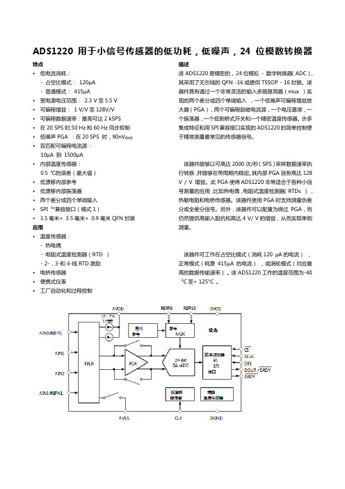
ADS1220用于小信号传感器的低功耗,低噪声,24位模数转换器特点•低电流消耗:- 占空比模式:120μA- 普通模式:415μA•宽电源电压范围:2.3 V至5.5 V•可编程增益:1 V/V至128V/V•可编程数据速率:最高可达2 kSPS •在20 SPS时,50 Hz和60 Hz同步抑制•低噪声PGA :在20 SPS 时,90nV RMS •双匹配可编程电流源:10μA 到1500μA•内部温度传感器:0.5 ℃的误差(最大值)•低漂移内部参考•低漂移内部振荡器•两个差分或四个单端输入•SPI ™兼容接口(模式1)• 3.5毫米×3.5毫米×0.9毫米QFN封装应用•温度传感器:- 热电偶- 电阻式温度检测器(RTD )- 2-,3-和4-线RTD激励•电桥传感器•便携式仪表•工厂自动化和过程控制描述该ADS1220是精密的,24位模拟- 数字转换器(ADC),其采用了无引线的QFN -16或提供TSSOP - 16封装。
该器件具有通过一个非常灵活的输入多路复用器(mux )实现的两个差分或四个单端输入,一个低噪声可编程增益放大器(PGA),两个可编程励磁电流源,一个电压基准,一个振荡器,一个低侧桥式开关和一个精密温度传感器。
许多集成特征和用SPI兼容接口实现的ADS1220的简单控制便于精准测量最常见的传感器信号。
该器件能够以可高达2000次/秒(SPS)采样数据速率执行转换,并能够在带周期内稳定。
其内部PGA涨势高达128 V / V 增益。
此PGA使得ADS1220非常适合于各种小信号测量的应用,比如热电偶,电阻式温度检测器(RTDs ),热敏电阻和电桥传感器。
该器件使用PGA时支持测量伪差分或全差分信号。
另外,该器件可以配置为绕过PGA,而仍然提供高输入阻抗和高达4 V/ V的增益,从而实现单侧测量。
该器件可工作在占空比模式(消耗120 μA的电流),正常模式(耗费415μA的电流),或涡轮模式(对应最高的数据传输速率)。
电路基础原理解读多路复用器和解复用器的工作原理

电路基础原理解读多路复用器和解复用器的工作原理电路中的多路复用器和解复用器是信号处理中常用的技术,它们能够在有限的通信资源下实现多个信号的传输和接收,提高了信号传输的效率和可靠性。
本文将解读多路复用器和解复用器的工作原理,介绍它们在电路中的应用和作用。
多路复用器(Multiplexer,简称MUX)是一种电子设备,能够将多个输入信号合并到一个输出信号上进行传输。
它工作的原理是利用控制信号选择输入信号中的一个进行输出。
多路复用器一般由多个数据输入端、一个控制输入端和一个输出端组成。
数据输入端将多个信号输入到多路复用器中,控制输入端通过控制信号选择其中一个输入信号进行输出。
多路复用器的工作原理可以通过一个简单的数字信号传输的例子来说明。
假设我们有4个数字信号需要传输,我们可以使用一个4位的多路复用器来实现。
多路复用器的数据输入端将4个信号输入到多路复用器中,控制输入端通过一个2位的控制信号来选择其中一个信号进行输出。
当控制信号为00时,多路复用器输出第一个输入信号;当控制信号为01时,多路复用器输出第二个输入信号,依此类推。
多路复用器在电路中的应用非常广泛。
例如,在数字电视中,多路复用器能够将不同频道的视频信号传输到一个输出信号中,实现多个频道的选择和切换。
在通信系统中,多路复用器能够将多个用户的数据信号合并到一个信道中进行传输,提高了信号传输的效率。
多路复用器能够有效地利用有限的通信资源,提供更多的功能和服务。
解复用器(Demultiplexer,简称DEMUX)是多路复用器的逆操作,能够将一个输入信号分解为多个输出信号。
它也由多个数据输出端、一个控制输入端和一个输入端组成。
控制输入端通过控制信号选择其中一个数据输出端进行输出。
解复用器的工作原理与多路复用器相反。
假设我们有一个解复用器和一个多路复用器相连,多路复用器的输出信号连接到解复用器的输入端,解复用器的控制输入端通过控制信号选择其中一个输出信号进行输出。
ADS1115数据手册中文翻译
9.3功能说明9.3.1多路复用器9.3.2模拟输入9.3.3满量程(FSR)和LSB大小9.3.4参考电压9.3.5振荡器9.3.6数字比较器(仅ADS1114和ADS1115)9.3.7转换就绪引脚(仅适用于ADS1114和ADS1115)9.3.8 SMbus警报响应9.4设备功能模式9.4.1复位和上电9.4.2操作模式9.4.3低功耗的Duty Cycling9.5编程9.5.1 I2C接口9.5.2从模式操作9.5.3写入和读取寄存器9.5.4数据格式9.6Register Map9.6.1地址指针寄存器(地址= N / A)[reset = N / A]9.6.2转换寄存器(P [1:0] = 0h)[reset = 0000h]9.6.3配置寄存器(P [1:0] = 1h)[reset = 8583h]9.6.4 Lo_thresh(P [1:0] = 2h)[reset = 8000h]和Hi_thresh(P [1:0] = 3h)[reset = 7FFFh]10应用与实施10.1申请信息10.1.1基本连接10.1.2单端输入10.1.3输入保护10.1.4未使用的输入和输出10.1.5模拟输入滤波10.1.6连接多个设备10.1.7快速入门指南9.3功能说明9.3.1多路复用器ADS1115包含输入多路复用器(MUX),如图25所示。
可以测量四个单端或两路差分信号。
另外,AIN0和AIN1可以与AIN3差分测量。
多路复用器由Config寄存器中的MUX [2:0]位组成。
当测量单端信号时,ADC的负输入通过多路复用器内的开关内部连接到GND。
ADS1113和ADS1114没有输入多路复用器,可以测量一个差分信号或一个单端信号。
对于单端测量,将AIN1引脚连接到外部。
在本数据手册的后续章节中,AINP指的是AIN0,AINN是指ADS1113和ADS1114的AIN1。
MTL830系列多路复用器的商业数据说明书

Eaton Electric Limited,Great Marlings, Butterfield, Luton Beds, LU2 8DL, UK.Tel: + 44 (0)1582 723633 Fax: + 44 (0)1582 422283E-mail:********************• Reduce the cost of installing hazardous-area cabling• Save installation time, space and weight • Highlight problems quickly with status reporting systems• Protect the process with sensor failure detection and safety drives • Connect directly to host systems through serial-data outputs• Analogue inputs to controllers with Modbus® communications •Redundant data highwaysMTL830 rangeMultiplexers for Zone 0 hazardous area applicationsMTL830 range of multiplexers with Modbus ® outputs provide a cost-effective alternative to single-loop isolation. The cost of installed wiring is reduced by up to 50% by communicating the input of multiple hazardous-area sensors over dual-redundant data highways. Further savings are achieved by reducing the number of inputs to the host, cabinet space and weight.A multiplexer transmitter, mounted in the hazardous area, catersfor thermocouple, RTD and mV analogue inputs. A compatible safe-area receiver provides serial Modbus® outputs for feeding to hostPLC, PC or DCS controllers.Dual-redundant data h igh ways between the transmitter and thereceiver allow continuous normal operation with only one highwayconnected. The highway cable, a simple twisted pair or a pair ofwires within an IS multi-core cable, carries both power and data, over distances up to 2km. If the multiplexer transmitter is located in the hazardous area, each data highway must be protected by an MTL3052 digital isolator.Multiplexer systems can communicate the status of up to 32 inputs, reducing the number of hazardous area wiring pairs from 32 to two.Reduce costs by eliminating long runs of expensive thermocouple compensation cable from the hazardous to the safe area. AIso, if 3- or 4-wire RTDs are used, costs are reduced by terminating each RTD at the transmitter or its enclosure.Dual redundant h igh ways increase system reliability. Failuredetectors and safety drives protect against the consequences ofsensor failure, while built-in systems report failures to the hostcontroller.Accessories include steel and stainless-steel enclosures, earth-leakage detectors and a PC-based configuration software package.For more information see AN9010, ‘A user’s guide to multiplexers’ and TP1098, ‘Cut the cost of intrinsic safety – by multiplexing!’The given data is only intended as a product description and should not be regarded as a legal warranty of properties or guarantee.In the interest of further technical developments, we reserve the right to make design changes.MTL831B multiplexer transmitters are normally sited in the hazardous area. They are connected to sensors in the field and communicate these inputs to the safe area via single-pair data highways. The data highways support communication between the safe and hazardous areas,and also provide power to the transmitters – no additional field power is required.The MTL831B would typically be mounted close to the field instruments in an enclosure such as the ENC8 or ENC83 (see 'MTL800 range of Enclosures').MTL831B ANALOGUE INPUT TRANSMITTERMonitors inputs from up to 16 THC or millivolt sources (max ±60mV) or up to 15 2-, 3- or 4-wire RTDs within a hazardous area.• Intrinsically safe; Zone 0 location• Communication and power pass over twin data highways • Powered by the data highway•Thermocouples and RTDs may be mixed on one transmitterMUL TI-DROPPING TWO MTL831BSTwo MTL831B multiplexer transmitters can share the same single-pair highway to a single safe-area isolator/receiver combination, providing up to 32 multiplexed inputs.DATA HIGHWAY CABLINGCabling with low capacitance and resistance is recommended to achieve greater distances between transmitters and receivers. See cable parameters in 'Basic Specifications' for specific requirements, and contact Eaton's MTL product line for latest cable recommendations. The system is designed to use both data highways, although it can be used with only one data highway in place. However, use of a single highway will increase response time.Data highway lengths of up to 2km in hazardous areas and 3km in safe areas have been achieved.ENCLOSURESA range of steel and stainless steel enclosures is available for mounting MTL831B units in the field (see 'MTL800 range of Enclosures'). ENC8 and ENC8SS (stainless steel) enclosures provide protection for a single MTL831B. The enclosures are dust-tight and waterproof to IP67.When using 4-wire RTDs, ENC83 and ENC83SS (stainless steel) enclosures provide additional terminals to accommodate the third and fourth RTD wires, which are not connected to the MTL831B itself.MTL838B-MBF receivers translate the information transmitted from the MTL831B via the data highway. The MTL838B-MBF provides a Modbus® serial-data output representation of the inputs together with status information.MTL838B-MBF MODBUS® ANALOGUE RECEIVERTranslates data received from the MTL831B in the hazardous area and makes it available as twin RS485 Modbus® serial data outputs. The MTL838B-MBF is configured by personal computer for thermocouple and RTD type, safety drive, high and low alarm and any other operational parameters.MTL3052 DATA HIGHWAY ISOLATORAn MTL3052 isolator is required for each data highway, when the transmitter is located in a hazardous area. It is not required for safe-area applications.MUL TI-DROPPING MODBUS® RECEIVERSUp to 31 Modbus receivers can be multi-dropped on a single RS485 link to the host system. Modbus® receivers can be controlled by any suitable Modbus® master. The receivers may be used with other Modbus® slaves on the same RS485 link.The given data is only intended as a product description and should not be regarded as a legal warranty of properties or guarantee.In the interest of further technical developments, we reserve the right to make design changes.The given data is only intended as a product description and should not be regarded as a legal warranty of properties or guarantee.In the interest of further technical developments, we reserve the right to make design changes.BASIC SPECIFICATIONS(see also 'Common specification')MTL831B (mV input)Number of input channels 16 THC or mV sources, potentiometer inputs up to 1kΩ)15 (RTD or mixed)(IS segregated and fully floating when used with MTL3052)Location of input sources Zone 0, IIC, T4Location of unitZone 0, IIC, T4Number of data highways Dual redundant (either or both)Power requirementLoop-powered through data highway from receiver No hazardous-area power supply required Multi-transmitter facility 1 or 2Ambient temperature limits–20 to +60°C working –40 to +80°C storage Weight1.3kgTypical response time 1s for each transmitter (input to receiver output)Electrical safety (each input circuit)U max:out = 15V I max:out = 16.3mA W max:out = 60mWInput sensor cable parameters BASEEFA values (C,L or L/R)(IIC)0.58µF,127mH or 535µH/Ω(IIB) 3.55µF, 486mH or 1087µH/Ω(IIA)14µF, 903mH or 1087µH/ΩElectrical safety (data highwaycircuit[s])U max:in = 30V maximum input parameters I max:in = 300mA W max:in = 1.2W C eq = 0, L eq = 0ADDITIONAL SPECIFICATIONSMTL831BEach input terminal block is user-selectable by switch for mixed mV, THC, 2- or 4-wire RTD input or 3-wire RTD input.Measuring ranges±60mV or ±25mV or ±10mV, auto ranging Common mode voltageMaximum 5V common mode between input channels of one transmitter mV signalsAccuracy at 20°C (including non-linearity and hysteresis)<0.1% of measuring rangeTemperature effects on accuracy {(greater of 0.01% of range or 2µV) + 0.01% of reading} /°CThermocouple signalsAccuracy at 20°C (including non-linearity and hysteresis)<0.1% of measuring range ±0.7°CUpscale/downscale drive does not introduce any accuracy errors Temperature effects on accuracy{(greater of 0.01% of range or 2µV) + 0.01% of reading + 0.03°C}/°C RTD signalsRTD range–200 to +850°C (Pt100 type, DIN 43760, IEC751: 1983)RTD excitation current 100µAAccuracy at 20°C (including non-linearity and hysteresis)<0.1% of measuring rangeTemperature effects on accuracy{(greater of 0.01% of range or 0.025°C) + 0.005% of reading}/°CThe given data is only intended as a product description and should not be regarded as a legal warranty of properties or guarantee.In the interest of further technical developments, we reserve the right to make design changes.BASIC SPECIFICATIONS(see also ‘Common specification’)MTL838B-MBF (Modbus® output)Number of data highways 2, dual redundant (either or both may be used)Location of unitSafe areaInput noise rejectionUp to 0.5mA peak-to-peak at 100 to 1000Hz, or up to 1mA peak-to-peak at 50HzType of output(s)Dual RS485 Modbus® protocol System protocolModbus® ASCII or RTU Serial communication parametersBaud rate: 300 to 19200Stop bits: 1 or 2Data bits: 7 or 8Parity bit: odd, even or noneMulti-receiver facilityUp to 31 MTL838B-MBF units can be connected to communicate with one Modbus® master controller Power requirement500mA at 20–35V dc Ambient temperature limits –20 to +50°C working –40 to +80°C storage Weight840gADDITIONAL SPECIFICATIONSMTL838B-MBFThermocouple range supportedTypes E, J, K, N, R and T THCs to IEC 584. Other options are available, please contact Eaton's MTL product line for details.System configurationSerial communications parameters and system parameters entered using PCS83 software program, by downloading from process controller. Configuration parameters are retained by using battery-backed RAM.LinearisationMulti breakpoint calculation by microprocessor (output is linearised and cold junction compensated)Broken THC indicationSerial output drives upscale or downscale Alarm facilitiesHigh and low alarms are indicated in the serial data and can be set for each inputThe given data is only intended as a product description and should not be regarded as a legal warranty of properties or guarantee.In the interest of further technical developments, we reserve the right to make design changes.This unit is similar in principle to the MTL3042 but operates at a higher frequency for use with digital signals. Its primary application is to provide IS protection for the data highways and transmitters in MTL800 range of multiplexer systems. The MTL3052 features two output circuits: one with a 15V, 180Ω safety description, and an alternative 15V, 100Ω circuit which can be used if higher loop resistances need to be accommodated, for example when surge protectors are incorporated in the data highways. If the low-resistance outputs are used on two units fitted to a dual-highway system however, the multiplexer transmitters are restricted to location in IIB atmospheres.SPECIFICATIONSee also 'Common specification'Number of channelsOne, fully floating Location of loadZone 0, IIC, T4–6 hazardous area if suitably certified Div 1, Group A , hazardous locationZone 0, IIB, T4–6 (Div 1, Group C, hazardous location)for multiplexer transmitters in dual-highway systems using the low-resistance outputs of two MTL3052s Input voltage4 to 12V dcSignal bandwidthdc to 10kHzMinimum output voltage[V in minus (0.25 x current in mA)] V Input and output circuit ripple<1mA peak-to-peakPower dissipation within unit160mW maximum at 12V with 20mA signal Replaceable fuse50mA, 5 x 20mm glass to DIN 41571 sht. 2, semi-time-lag (M)‘No-fail’ earth fault protection (optional)Enabled by connecting terminal 8 to MTL4220Fault on either line proclaimed: unit continues working Safety descriptionTerminals 5 & 615V, 100Ω, 150mA, U m = 250V rms or dc Terminals 7 & 815V, 180Ω, 83.3mA, U m = 250V rms or dc FM max entity parametersV oc = 15V, I sc = 83.3mA, C a = 0.75µF, L a = 5.2mH Weight130g Cable parameters - BASEEFA values (data highway circuits, each highway)Terminals 7 & 8Terminals 5 & 6Grp C µF L mH L/R µH/ΩC µF L mH L/R µH/ΩIIC 0.58 5.21090.58 1.6565IIB 3.5515.6327 3.55 4.95195IIA1441.68721413.2520OTHER APPLICATIONSThe MTL3052 is suitable for a variety of other applications, such as bringing back the status of a hazardous-area mechanical or opto-transistor switch, or a magnetic shaft encoder (all via suitable current limiting resistors).The given data is only intended as a product description and should not be regarded as a legal warranty of properties or guarantee.In the interest of further technical developments, we reserve the right to make design changes.Maximum loop impedance (each data highway)50Ω when using MTL3052 interface (terminals 7 & 8)130Ω when using MTL3052 interface (terminals 5 & 6)300Ω for non-IS applicationsTransmission distance (transmitter to receiver)0.5km typically (IS applications)1.5km typically (non-IS applications)For many applications it is possible to use longer distances up to 3km, for details consult Eaton's MTL product line Intrinsically safe interface (IS applications)1 MTL3052 isolating interface unit for each data highway Earth fault protection (optional)An optional MTL4220 earth leakage detector will detect line-to-earth faults on either line of either highway.Data highway monitoringHighway 1 LED, green (located on receiver)ON when highway 1 connected and operating Highway 2 LED, green (located on receiver)ON when highway 2 connected and operating Highway 1 & 2 statusSerial output receivers: condition of highway(s) transmitted in unit status word to process controller System failure monitoringSystem failure LED, red (located on receiver)ON when both highways disconnected or faulty or when there is an internal receiver fault System failure signalSerial output receivers: derived from status word Power supply failureAll relays and LEDs de-energiseHumidity5–95% RH (without condensation)EMC complianceEN 50081-2/EN 50082-2, generic emission/immunity standards. These refer to appropriate IEC/CISPR standards.TerminalsDetachable, each accommodates two 2.5mm2 conductors CasingsMoulded polycarbonateCONDITIONS OF USEThe conditions governing the use of MTL800 range of multiplexers are given in the relevant certificates and schedules, copies of which are available from Eaton's MTL product line.DIMENSIONS (mm)(in extended position)The given data is only intended as a product description and should not be regarded as a legal warranty of properties or guarantee.In the interest of further technical developments, we reserve the right to make design changes.SPECIFICATIONSENC8/ENC8SS: for 1 MTL831B transmitter, or 1 MTL838B receiverENC83/ENC83SS: for 1 MTL831B transmitter (for use with 4-wire RTDs)LocationZone 0, 1 or 2ProtectionDust-tight and waterproof to IEC529:IP67Construction (ENC8 and ENC83)Sheet steel, zinc sprayed and painted RAL7015 grey Construction (ENC8SS and ENC83SS)Stainless steel LidDetachable with lift-off hinges, secured by captive fixing screws with a padlock hasp Earth terminalsFitted on internal earth rails; accommodate conductors up to 4mm2Number of earth terminalsENC8/ENC8SS: 22ENC83/ENC83SS: 184-wire RTD terminals (ENC83/ENC83SS only)32 ready-mounted terminals to accommodate conductors up to 4mm2Gland fixingTop and bottom gland plates detachable for drilling by user MountingBy fixed mounting lugsWeight (excl. transmitters/receivers)ENC8: 7kg ENC83: 9.8kgDIMENSIONS (MM)SPECIFICATIONSPCS83 software package (for MTL838B-MBF)Function : Software configuration of multiplexer system Format : 3.5 inch diskette Requires: PC with DOS 2.2, or higher, and a serial (COM) port.TO ORDER, SPECIFY:Transmitters MTL831B Analogue transmitter ReceiversMTL838B-MBF Analogue receiver, RS485 and/or RS422outputs for Modbus®Analogue receiver accessoriesPCS83 PC software configuration package Process controller interface softwareContact Eaton's MTL product line for details of software for interfacing with proprietary process controllersIsolating interface units and earth leakage detectorsMTL3052 Digital isolator interface unit MTL4220 Earth leakage detector EnclosuresENC8 General-purpose enclosure ENC8SS General-purpose enclosure (stainless steel)ENC83 Enclosure for MTL831B transmitter ENC83SS Enclosure for MTL831B transmitter (stainlesssteel)LiteratureINM838B-MBF System protocol manual: MTL838B-MBF Modbus® receivers INM831B MTL831B manual AN9010 Application Note: A user's guide to intrinsicallysafe input multiplexer systemsINS831B MTL831B mV Multiplexer transmitter INS838B MTL838B-MBF Multiplexer receiver - Modbus®outputAB C D ENC8331306203306ENC83407380305466。
什么是电子电路中的多路复用器

什么是电子电路中的多路复用器在电子电路中,多路复用器(Multiplexer,简称MUX)是一种重要的数字电路元件,它的作用是实现多个输入信号中的一个信号经过选择后输出。
1. 多路复用器的基本原理多路复用器的基本原理可以用模拟电路中的开关来进行简单的描述。
假设有一组开关,每个开关对应一个输入信号,而多路复用器则控制这些开关的打开和关闭。
当多路复用器将某个开关打开时,对应的输入信号便通过该开关并输出;反之,当多路复用器将某个开关关闭时,对应的输入信号则不会通过该开关。
2. 多路复用器的结构和工作原理多路复用器一般由两部分组成:控制逻辑和数据选择部分。
控制逻辑负责接收控制信号,并根据信号的不同来控制数据选择部分的工作。
数据选择部分则根据控制逻辑的指令选择相应的输入信号,并将选择的信号输出。
多路复用器的工作原理可以简单描述如下:首先,控制逻辑通过控制信号指定需要选择的输入信号数量,比如2个、4个或者更多。
接着,数据选择部分根据控制信号选择对应数量的输入信号,并将选择的信号通过电路连接至输出端。
最后,输出端将选择的信号输出,供后续电路使用。
由于多路复用器可以选择多个输入信号中的一个,因此它常用于减少电路的复杂性和节省空间。
例如,多路复用器可以用于选择不同的数据源输入到一个共享的总线上,从而提高系统资源的利用率。
3. 多路复用器的应用多路复用器在数字电路和通信系统中有广泛的应用。
以下是一些常见应用示例:3.1 数据选择器多路复用器可以作为数据选择器使用,用于选择多个输入数据中的一个输出。
例如,在计算机的输入输出模块中,可以用多路复用器来选择不同的输入设备,如键盘、鼠标或者其他外部设备。
3.2 传输系统在通信系统中,多路复用器可以将多个信号通过同一条物理通道进行传输,从而节省通道资源。
例如,在电话网络中的时分多路复用技术(TDM)中,多个电话信号可以使用时分复用技术合并在同一条电话线路上进行传输。
3.3 数字显示器多路复用器可以用于数字显示器的控制。
MX30 控制服务器 用户手册说明书
MX30控制服务器用户手册更新记录目录更新记录 (i)目录................................................................................................................................................................................................................. i i1 简介 (1)2 外观 (2)2.1前面板 (2)2.2后面板 (2)3 应用场景 (6)4 液晶界面 (7)4.1主界面 (7)4.2主菜单 (9)5 初始配屏 (10)5.1液晶快捷配屏 (10)5.1.1设置输入源 (10)5.1.2载入箱体配置文件 (11)5.1.3快捷配屏 (12)5.2 VMP自由配屏 (12)6 显示效果调节 (13)6.1应用预设方案 (13)6.2设置外部输入源参数 (13)6.2.1查看输入源信息 (13)6.2.2设置分辨率和帧频(仅HDMI1、HDMI2、DP) (14)6.2.3调节颜色 (14)6.2.4设置HDR参数(仅HDMI1) (15)6.3设置内置源参数 (16)6.4设置输出参数 (16)6.4.1调节亮度 (16)6.4.2调节Gamma和色温 (17)6.4.3设置低延迟 (18)6.4.4设置输出位深 (18)6.4.5设置同步信号源 (19)6.5设置图层(视频控制器模式支持) (20)7 设备管理 (22)7.1切换工作模式 (22)7.2设置备份设备 (22)7.3进行通讯设置 (22)7.4开启MAPPING (23)7.5控制画面状态 (24)7.6设备自检 (24)7.7查看固件版本 (25)7.8恢复出厂设置 (26)8 系统基本设置 (27)8.1设置语言 (27)8.2设置返回主界面时长 (27)8.3设置温标 (27)8.4查看服务信息 (28)9 产品规格 (29)10 视频源规格 (30)11 网口带载规格 (31)MX30是西安诺瓦星云科技股份有限公司(以下简称“诺瓦星云”)全新控制系统COEX系列下的一款二合一控制服务器,集视频处理和控制功能于一体,具有丰富的视频输入接口(HDMI 2.0、HDMI 1.4、DP 1.1、3G-SDI),10路输出网口和2路10G光纤接口,支持全新的视觉管理平台VMP,为用户提供更好的操控体验。
多路复用技术解析
3.空分多路复用技术SDM :
空分多路复用(SDM,Space Division Multiplexing)即多对电线或光纤共用1条缆的复用方式。 比如5类线就是4对双绞线共用1条缆,还有市话电缆(几十 对)也是如此。能够实现空分复用的前提条件是光纤或电线 的直径很小,可以将多条光纤或多对电线做在一条缆内, 既节省外护套的材料又便于使用。
4.波分多路复用技术WDM :
Λ1=1535nm
Tx
Λ1=1543nm
Tx
Λ1=1550nm
Tx
Λ1=1557nm
Tx
发送器
多路器
Λ1 Λ2 Λ3 Λ4
Λ1=1535nm
Tx
Λ1=1543nm
Tx
Λ1=1550nm
Tx
Λ1=1557nm
Tx
多路器
接收器
5.码分多路复用技术CDMA :
码分多路复用(code division multiplexing)是频分 多路复用(Frequency Division Multiplexing)与时分 多路复用(Time Division Multiplexing)两种技术的复 合,频分复用是按频域正交来划分信号,时分复用是按时 域正交来划分信号。同样码分多路复用是利用码间的正交 性来划分信号。利用正交编码来实现多路通信的方式称为 码分复用。
2.时分多路复用技术TDM的分类 :
时分多路复用(TDM)又分为:
①同步时分复用(Synchronous Time Division Multiplexing,STDM) 同步时分复用采用固定时间片分配方式,即将传输信 号的时间按特定长度连续地划分成特定的时间段(一个周 期),再将每一时间段划分成等长度的多个时隙,每个时 隙以固定的方式分配给各路数字信号,各路数字信号在每 一时间段都顺序分配到一个时隙。
COMPAX XX30用户指南说明书
COMPAX XX30Subject to technical change. Data represents the technical status at the time of closing for press.30.09.99192-043014 N2O p e r a t i n g I n s t r u c t i o n sI n d e x i n g T a b l e C o n t r o l- S u p p l e m e n t t o U s e r G u i d e C O M P AX -M /S -COMPAX-MPower Supply From software version V3.64October 98W e a u t o m a t e m o t i o nCOMPAX XX302Inhalt1 Overview......................................................................22 Configuration.. (3)2.1 Moment of Inertia.................................................32.2 Gear Ratio i..........................................................32.3 Position Measuring...............................................43 Reference Drive ..........................................................44 Commands (4)4.1 Positions Commands...........................................44.2 Indexing Calculator..............................................54.3 Hand Operation....................................................55 Special Inputs and Outputs (6)5.1 Functions of Inputs...............................................65.2 Functions of Outputs............................................66 Special Status Assignment........................................67 Additional Error Messages...........................................68 Indexing Table Parameters. (7)This manual applies to the following devices:COMPAX 2530S COMPAX 4530S COMPAX 8530S COMPAX P130M COMPAX 0230M COMPAX 0530M COMPAX 1530M COMPAX 3530MCode of device designatione.g.: COMPAX 0260M:COMPAX:Name 02:Power class 60:Variant e.g. "00": Standard deviceM:Device type; M: Multi axis device E: Single axis deviceHAUSER-nameplateThe nameplate is on the top of the device and has the follo-wing structure:1OverviewWith COMPAX XX30 indexing tables, endless or batch quantity assembly chains can be position controlled with high precision.The positions are programmed in degrees. The direction of rotation can be positive or negative.Apart from the standard-command set of the COMPAX standard which is not described here in detail (see user guide COMPAX M/S) a special command is used for the indexing calculator. Tha table can be subdivided in the same angle segments with the indexing command.The standard position measurement follows the resolver in the motor. An external position measuring device to increase the positioning precision is supported.The indexing table control differs from the COMPAX M standard device in the following features:Required opti-ons:no; Option E2 or E4 for external posi-tion measuringPossible Opera-tion Modes As in the standard device extended to the reset mode Acceptable Drive Types:Indexing table control;Universal driveAdditional Commands:WAIT POSR n indexing calculator Positioning to arc segments, without rounding errors.Locked Com-mands:SPEED SYNCGOSUB EXT and GOTO EXT re-stricted to I9 (I11)Label related positioningModified Confi-gurationRange of the gear ratio:1,000000...1000,000000The moments of inertia are given with-out moment of inertia of the motor. Distances are given in angles (360°)Modified Commands-Modified I/O Functions:I12:Switch currentlessI13:Compensation of measurementerror via external position sensor I14:Release brakeO14:No measurement error O16:Output stage currentless SpecialParameters:P1:Real zero-360...360 degree P11:+4000000 fixed P12:-4000000 fixedP98:Distance per table rotation P75:Maximum measuring error P214:Measurement direction of theexternal measurement Modified Status:S41:Encoder speed S42:Encoder position S46:Sign encoder speed S47:Measurement error S48:Actual valueS49:Target position after divisioncalculation Miscellaneous:Absolute encoder function not possible!32ConfigurationBefore configuration the drive has to be currentless!Instead of the configuration course with the standard operation instruction, you must note the following at the indexing table control:New opera-tion modeP93"Reset mode" (P93="3").P93="3" is the standard adjustment for indexing table control Caution!In the reset mode …inch“ and…increments“ units are not possible!New unit for distancesP90Unit degree P90="3": 0-360°For the configuration of the motor type , the ramp profile and the direction the details used in the standard operation instruction of COMPAX M are valid.Drive type P80P80="64": Indexing table controlchooseP81P82P85indexing table controlP81: Minimum moment of inertia Moment of inertia converted to the motor side. Range:0...P82P82: Maximum moment of inertia Moment of inertia converted for the motor side. Range:0...200000kgmm 2P85: Gear ratioRange: 1,000000...1000,000000See chapter 2.1 u. 2.2.Drive type P80P80="16": Universal drivechooseP81P82P83P85P81: Minimum moment of inertia Moment of inertia converted to the motor side. Range:0...P82P82: Maximum moment of inertia Moment of inertia converted for the motor side. Range:0...200000kgmm 2P83: Travel per motor revolution in milli degreeConfiguring the direct position measurementSee chapter 2.3 und 3ResolutionP143Resolution per table rotationRange: 500...2 000 000≤ 214* gear ratio Distance per rotation P98Distance per table rotation Fixed adjustment: P98 = 360Measure-ment di-rection of the external measure-mentP214"0":positive direction when the tablegoes right."1":positive direction when the tablegoes left.Caution!Notice the following section when adjusting the measurement direction.At first start up of the external position measuring system it is possible that, due to a direction change through the gear, the rotating direction of the encoder is opposed to the resolver.Therefore the [I13=1] position correction will operate in the opposite direction. This results in an increase of themeasurement error and the device will be disabled via the error message "error 15".The following start up sequence therefore has to be followed:1.External measurement not active: I13 = 02.Configure resolution external measurement system3.Set parameter P75 to small value (typical 1°)4.Connect external measurement: I13 = 15.No error: Æ o.k.6.Error 15:Parameter P214 change measurement di-rection from 0 to 1 and acknowledge errorThe counting direction of the external encoder will be inverted through the change of the measurement di-rection.Machine zeroP213You can select with P213, at the in-dexing table control, the side of the machine zero initiator which will be evaluated as machine zero.Value: "0" / "1"Software end limits P11,P12Fixed adjustment:P11=+4000000P12=-4000000Real zero pointP1Range: -360...360 degree2.1Moment of InertiaThe data of minimum and maximum moment of inertia refer to the moment of inertia of the gear and indexing table, the units are given in kgmm 2. They have to be calculated as seen on the motor shaft, therefore the gear ratio has to be considered.Normally large gear ratios will be used, so that the additional moment of inertia of the pay load can be neglected and set to 0.COMPAX takes the moment of inertia of the motor from the internal motor table.2.2Gear Ratio iRange:i = 1,000000...1000,000000For a whole number gearing the reference point can be de-fined via the logical AND-connection of machine zero initia-tor with the resolver zero impulse (COMPAX standard appli-cation). No external position measuring system is required.With a gear ratio which is not a whole number the resolver zero impulse shifts at every table movement, the calculation of the resolver information becomes inaccurate. In this case an external position measuring system is required.COMPAX XX3042.3Position MeasuringFor the inner control loop COMPAX always needs a resol-ver, regardless whether an external measurement system exists. The position accuracy is 15', related to the motor shaft. This accuracy results from the tolerance of the resol-ver. The repeatability is in the order of 1,3' (corresponds to 214 counts per motor rotation).If the accuracy of the resolver is not sufficient or the gear ra-tio is not a whole number, an external position measuring system is required. For control of the servo loops, the actual value from the resolver is still used. This value will be cor-rected with the value of the external position measuring sy-stem. This has the following advantages:The dynamic response is not dependant on the external position measurement system.Start up is possible without an external measurement sy-stem.Filtering of the external measuring signal is possible without a loss of dynamics.Activation of external position measuring:To increase the accuracy of positioning, the measurement error compensation can be activated via input I13. First, the resolution has to be configured (via the configuration menu or with P143).I13 will be polled before every positioning. So you can de-cide at any time to position by resolver or external encoder.If no resolution is configured (P143=0), input I13 will not be polled and the measurement error compensation will not be activated.If the difference between resolver position and the position which is measured externally is larger than the maximum measurement error P75, an error message "E15 measure-ment error" will be displayed and output O14 "no measure-ment error" will be reset to 0. The drive will then be disabled.The error message can be acknowledged with function key "Enter".3Reference DriveUsually the reference (home) position is determinated by the external machine zero initiator and resolver zero impulse.The rotation direction hereby is negative, related to the mo-tor (for direction P215 ="0").For direct position measurement and whole number gear ra-tio the home position can be determined by the zero impulse of the position measurement system. A MN-Initiator is not needed, the position measurement system is mounted di-rectly at the table.For applications with a 2-step gear and the mounting of the position measurement system after the first step, a MN initia-tor is needed at the table.With P212 you can adjust several reference modes (see User Guide COMPAX-M/S).The operation with end-initiators is not possible.4CommandsAs a comparison with the standard commands of COMPAX the following modifications apply:4.1Positions CommandsThe positioning default values are related to the angle of the table. They are measured in degrees and have to be in the range of -360,000 ... 360,000 degrees.After every table rotation the position set points and actual values are reset, so that the actual values are in the range of 0 ... 360 degree.Absolute PositioningThe absolute target position value with POSA lies in the range of 0...360 °. This is within one table rotation. The di-rection of rotation is dependent on the travel difference (new target point - old target point).E.g.1:E.g.2:Relative PositioningAt a relative target reference positive and negative values are allowed: POSR -360...360. The direction of rotation is selected with the sign.With parameter P215 the polarity of all position values can be changed.With a suitable combination of absolute and relative positio-ning commands an optimum indexing operation is possible.E.g.:N001:REPEAT 10number of repetitions N002:POSR 33move forward for 33° 10 times N003:WAIT START wait for start at position 330Degfrom zero positionN004:END N005:POSA 0back to zero position ( -330°)oderN005:POSR 30optimum distance to zero position oderN005:POSA 36054.2Indexing CalculatorWith the indexing calculator you can position to arc seg-ments, without adding the rounding error.Command:WAIT POSR n n:+/-1 (999)The sign of n gives the direction of rotation.A circle is divided into "n" segments. With every processing of the command "WAIT POSR n" it is moved forward by one segment. To avoid rounding errors the specific target posi-tion is determined with the following rule:360 degreeTarget position =------------ * indexing step + basic positionnn:indexing factorTeilungsschritt:internal step counterBasisposition:start position of the indexing calculator.It will be actualised before the first indexing step.Example: n = 7To calculate the target position the indexing calculator does not use the angle α, which is full of rounding errors, but the target position related to the whole circle. This ensures that after the positioning movements 360° is reached exactly.Example for a fixed number o f part steps:N001:REPEAT m repeat factor m < 65536N002:WAIT POSR n next indexing step N003:WAIT START wait until start at I5N004:ENDThe REPEAT loop gives the total number of the indexing steps to be executed. The table will wait at every position for a new start signal at I5.Example for a variable number of part steps:N001:IF I7=0 GOTO 1start of the move cycle with I7N002:WAIT POSR n next indexing step N003:OUTPUT O7 = 1activate processing N004:WAIT 100processing N005:OUTPUT O7 = 0switch off processing N006:IF I8 = 0 GOTO 1switch further N007:WAIT POSR 0delete indexing counter This case is similar with the REPEAT loop, the indexing counter will be raised by 1 with every partition. The loop can be left at any time with I8 = 1 and the present segmentation will be lost.Additional function:WAIT POSR 0With this command the internal indexing counter (counter of the indexing steps) will be reset to one. By so doing the actual indexing calculation is deleted.Interruption of the indexing calculatorThrough a new indexing calculator with other indexing factors or through the command …search machine zero point“ the pedometer will be set to one and the basic position set to the current position.With the commands POSA, POSR the indexing calculation will not be influenced.Example:With the program sequence drive to real zero (SHIFT I3)N001:POSR 10relative + 10 degree N002:REPEAT 5 5 stepsN003:WAIT POSR -12 partion -360/12 = -30 degree N004:END end of the loop N005:POSR 140relative + 140 degree the following angles will be driven to:Position:010340310280250220360Direction:+-----+With the following sequence N006:WAIT POSR 0N007:GOTO 2the above program example will be repeated cyclically, the indexing calculation will be restarted each time.4.3Hand OperationThe hand operation is handled like a positioning move.An activated indexing calculation will not be influenced by hand operation. The indexing calculation refers to the last indexing step by continuing the process.COMPAX XX3065Special Inputs and Outputs5.1Functions of InputsSwitch currentlessI12l12 will not be evaluatedduring a positioningand during the sentence processing, i.e. also in theCam operation.With I12="1" the output stage is enabled. With I12="0" the output stage is currentless.Measurement error compensationI13I13 is only used in external position measurement opera-tion.With I13="1" the actual value of the resolver will be com-pared and corrected with the external position measure-ment. If the error is larger than P75, error I15 will be gene-rated and the drive will be disabled.Release brake I14With I14="1" the brake will be released by currentlessoutput stage.5.2Functions of OutputsNo measurement errorO14O14="0" corresponds with error E15: measurement errorO14="1" no measurement error"Output stage currentless"O16O16="0": Output stage active O16="1": Output stage currentless6Special Status AssignmentS12:Encoder position: in degree; referred to the tableS41:Encoder speed: motor speed diverted from the encoderin % of the motor nominal speed S42:Encoder position: see S12S46:Sign Encoder speedS47:Measurement error: difference between encoder- andresolver position in degree S48:Actual value: (corresponds S1)S49:Target position of the division calculation: in degree7Additional Error MessagesError 15:Measurement errorMeasure:Check configuration (gear rate or resolution)and control wiring; check measuring wheel di-rection.Recommendation by E15 error message:After Quit of external position measurement,switch off for a short time with l13="0"!78Indexing Table ParametersNo.MeaningUnitMinimum ValueDefault ValueMaximum ValueValid from...Indexing Table ParametersP1Real zero point Degree-360,000360,0001P212Reference procedure"1": Resolver and machine zero "3":Encoder"4":Encoder and machine zeroVPP75Maximum measurement errorDegree 0,011,00360,00VP P68Measurement filter: <100%: leading >100% trailing (Filtering)%101005000VP P80Drive typ="16":Universal drive ="64":Indexing table controlVCP81Minimum moment of inertia kgmm 200P82VC P82Maximum moment of inertiakgmm 200200 000VC P83Travel per motor revolution for drive type "universal drive"Degree 1000360 000VC P85Gear ratio for drive type "indexing table control"-1,0000001000,000000VC P90Units for distance indication (extended)"0":Increments "1":mm "2":Inch"3":Degree (Extension); by "Universal drive "in milli degree (1/1000 Degree)VCP93Operation modes"1":Normal operation "2":Endless operation"3":Reset mode (Extension)"4":Speed control operationimme-diatelyP98Distance per encoder revolutionDegree 360360360VC P143Resolution of the external position measurement system 002000000VC P144Channel 1 = external encoder= "6"VC P214Measurement direction of the external measurement"0", "1"VPAll not indicated inputs, outputs and parameters are assigned like COMPAX-standard (see User Guide COMPAX-M/S).1From the next positioning POSA or POSR.For activated indexing calculator a modified real zero will not be adopted. For a new indexing calculation a POSA or POSR command is first necessary.COMPAX XX30 8。
RC3000(REV.B) 综合业务交叉复用设备用户使用手册200903
2
瑞斯康达科技发展股份有限公司
目录 1. 概述 .................................................................................................................................. 1
增加 RC3000-SUB-DETHx2 板卡的 说明,和 Console 控制 增加 RC3000-SUB-DV24 板卡的说 明,和 Console 控制 增加 RC3000-SUB-DC64K 板卡的 说明,和 Console 控制
高双权修改 李英喜 曾宇
1
瑞斯康达科技发展股份有限公司
安全注意事项
———————————————————————————————————————
声明
Copyright ©2008 瑞斯康达科技发展股份有限公司 版权所有,保留一切权利。 非经本公司书面许可,任何单位和个人不得擅自摘抄、复制本书内容的部分或全部,并不得 以任何形式传播。
是瑞斯康达科技发展股份有限公司的注册商标。 对于本手册中出现的其它商标,由各自的所有人拥有。 这里的产品和服务名称都为北京瑞斯康达科技发展有限公司的商标。 由于产品版本升级或其它原因,本手册内容会不定期进行更新。除非另有约定,本手册仅作 为使用指导,本手册中的所有陈述、信息和建议不构成任何明示或暗示的担保。
RC3000 综合业务交叉复用设备 用户使用手册
REV.B
司
- 1、下载文档前请自行甄别文档内容的完整性,平台不提供额外的编辑、内容补充、找答案等附加服务。
- 2、"仅部分预览"的文档,不可在线预览部分如存在完整性等问题,可反馈申请退款(可完整预览的文档不适用该条件!)。
- 3、如文档侵犯您的权益,请联系客服反馈,我们会尽快为您处理(人工客服工作时间:9:00-18:30)。
MUX30多路复用设备用户手册 MUX30 multi-service access system
用 户 手 册 MUX30多路复用设备用户手册 致用户:
⑴ 感谢阁下使用我公司的产品。本设备在设计使用范围内具有良好可靠的性能,但仍应避免人为对设备造成的损害或破坏。请在使用本产品前,仔细阅读本用户手册,并妥善保管,以备参考使用。 ⑵ 安装本产品前请核对型号,并按用户手册要求安装。 ⑶ 请勿让本产品淋雨或受潮,以免损坏。 ⑷ 不要在电源电缆上放任何东西,不要将电缆打结或包住。为避免引起火灾,应将其放在不易碰到的地方。 ⑸ 电源接头以及其它设备连接件应互相连接牢固,请经常检查。 ⑹ 请注意设备清洁,必要时可用软棉布擦拭。 ⑺ 请注意不要堵塞通风散热孔。 ⑻ 请不要自己修理设备,除手册中有明确指示外。当设备运行异常时请立即断电并与公司售后服务部联系。 ⑼ 本公司对由合法渠道取得产品的用户提供三个月包换、一年免费质保、终身维护服务。 免费维修服务的有关事项如下:在一年保修期内,如按使用说明书正确使用,并在正常使用情况下发生故障,本公司将负责免费维修;凡将设备自行打开,本公司将不负责维修;超过保修期的设备,我公司仍负责维修,适当收费。
⑽ 在质保期内由于产品本身质量问题而造成的设备不能正常运行使用,本公司负责更换,回收的产品由本公司所有。人为对设备造成的损害或破坏,或没有按照本手册操作造成对设备的损伤,我公司概不负责。 版权声明
本产品的所有部分,包括本手册及配件等,其所有权归属本公司所有。未经书面许可,不得任意仿制、拷贝、誊抄、转译或以任何形式在网络中传送。 对于以任何形式修改产品及本说明书而造成的产品功能不能实现或对其他产品、人身造成影响,本公司将不负任何责任。 除此之外,本手册所提到的产品规格和资讯仅供参考,内容亦会随时更新,恕不另行通知,有关信息请向公司查询。 MUX30多路复用设备用户手册 MUX30 multi-service access system
1:简介 MUX30 multi-service access system多路复用设备是本公司采用自主知识产权的大规模集成电路,应用PCM30/31制式将以太网业务、话路业务、V35业务、RS232业务、二/四线等通过E1接口混合传输。该机采用19英寸、1U机框设计,集成度高,体积小,功耗低,工作可靠,安装使用方便。
2:主要功能与特点
提供2路E1接口; 提供30个用户接口; 用户接口可插话路小板、V35小板、RS232小板、二/四线音频小板、二/四线EM小板、以太网小板、热线小板、RS485小板、基带小板等; 电源为DC-48V,DC+24V,DC-24V,AC 220V等; 提供完善的本端/对端告警监控; 3:技术指标 3.1 E1接口 设备有2路E1接口,符合G.703建议 速率:2048Kb/s ±50ppm 码型:HDB3 阻抗:75Ω(非平衡)或120Ω(平衡) 抖动:符合G.742 G.823建议 输入口允许衰减: 0~6dB E1接头:JB9 3.2 以太网接口 支持线速10Base-T/100Base-T,全双工/半双工自适应 符合IEEE802.3/IEEE802.3u标准 使用标准RJ45插头 3.3 V.35接口特性 标称速率:2048K/s 支持分帧与透明两种方式 接口:使用标准RJ45插头 工作方式:DCE,DTE可选 MUX30多路复用设备用户手册 3.4 RS-232(V.24)串口接口特性
接口方式: RS-232 接口电平:RS-232电平 接口:使用标准RJ45插头 接口速率为:低于57.6Kbps的异步数据 3.5 话路接口及信令 交换侧 摘机阻抗: < 500Ω 挂机阻抗: > 10KΩ 用户侧 环路阻抗: ≤2000Ω(包括话机) 空闲电路电压 ≤ 50V 环路电流: 25mA 摘机门限: 8mA 极性反转时延: < 50ms 拨号: 脉冲拨号单脉冲失真< 5ms 带内音频拨号总失真满足话音接口特性 摘机时延: < 100ms 铃流: 远端(FXS)铃流发生器 频率: 25 Hz±3 Hz 幅度: 75V±5Vrms 铃流时延 < 50ms 输出总功率 ≤ 10W(以机箱为单位) 局端(FXO)铃流检测 幅度范围: 最小38Vrms 话音接口 阻抗: 600Ω或三元件复式阻抗,如图所示
三元件复式阻抗 音频范围: 300-3400 Hz 编码律: CCITT建议G.711 A律 二线接口电平:二线发 0dBr 二线收 -3.5dBr MUX30多路复用设备用户手册 四线接口电平:四线发 0dBr 四线收 0dBr 回损: 300-600 Hz > 12dB 600-3400 Hz > 15dB 频率响应: 300-3400 Hz (+0.5,-0.5dB) 空噪: ≤-65dBm0p 增益: -45 dBm0——+3 dBm0(+0.5,-0.5dB) 总信噪比: 符合ITU G.713样板如图所示
模拟(四线至四线或二线至二线)信道的 信号/总失真与输入电平的关系
3.6 2/4线接口规范: 压缩率: ITU G.711中A律 阻抗: 平衡600Ω 音频范围: 300Hz―3400Hz 回波损耗: 不低于18Db 3.7 功耗
整机功耗 <30W 3.8 工作环境 工作温度: 0~45℃ 相对湿度: ≤95%(25℃时) 大气压力: 70~106Kpa MUX30多路复用设备用户手册 4:设备组成
4.1 前面板
前面板示意图 整机具有完善的工作状态及告警指示,并具有声音报警功能; 前面板指示灯从上到下依次说明如下: 电源指示灯(PWR):当系统电源开关打开后此绿灯亮 E1告警指示灯: LOS1: E1指示灯,当收到E1信号时LOS灯灭。 LOF1: 帧失步,发生E1链路帧失步时,此红灯亮 AIS1: 远端2M没有连接好,此红灯亮 LOS2: E1指示灯,当收到E1信号时LOS灯灭。 LOF2: 帧失步,发生E1链路帧失步时,此红灯亮 AIS2: 远端2M没有连接好,此红灯亮 业务指示 1- 30指示为业务1-30路状态指示。 4.2 后面板指示说明
后面板示意图 1:IN1、OUT1为第1路E1接口,IN2、OUT2为第2路E1接口;
2:P1-P15为1-30路业务接口,业务接口为RJ45接头; 3:P16为网管监控接口;
5. 用户接口 以下列举了常用小卡的说明。小卡出线线序及拨码开关定义如果有所更改,将会在附录中阐述。请先查阅附录。如果附录中没有的项目说明就请参照下列说明文字及表格。
MUX30的各个用户接口卡通常以立体插装形式安装在主板上。 MUX30多路复用设备用户手册 业务插卡有单路、双路两种形式。插卡的槽位为:第一个槽位对应P1接口、第N个槽位对应PN个接口。
5.1局端电话接口卡:FXO FXO接口卡主要完成:用户话音信号与ST-BUS主板信号的相互转换;用户线状态信号与数字信令之间的相互转换;并为网管提供识别和状态信息;
FXO卡主要用于连接自动用户电话交换机、共电电话交换机等的接口。 FXO通常与FXS配合使用。 本卡支持来号显示功能,同时本卡也支持反极计费功能。 FXO卡以每卡2路的形式提供,每个接口出二路,即P1-P15每个口出二路。 远端摘机,设备面板上对应的状态灯亮。远端振铃时,设备面板上对应的状态灯闪亮。 5.2 用户端电话接口卡:FXS FXS接口卡主要完成:用户话音信号与ST-BUS主板信号的相互转换;向电话用户馈电;过压和过流保护;被叫时向用户送铃流;监视用户摘挂机状态;用户线状态信号与数字信令码之间的相互转换;并为网管提供识别和状态信息;
FXS可以用于自动电话、共电电话、计费电话等远端电话接口。 FXS通常与FXO配合使用; 本卡支持来号显示功能,同时本卡也支持反极计费功能; FXS卡以每卡2路的形式提供;,每个接口出二路,即P1-P15每个口出二路。 远端摘机,设备面板上对应的状态灯亮。远端振铃时,设备面板上对应的状态灯闪亮。 5.3 EM2/4线接口卡:EM2/4
EM2/4线用户接口卡主要完成:用户话音信号与ST-BUS主板信号的相互转换;音频2/4线状态设置;收发增益的设置;EM信令线状态信号与数字信令之间的相互转换;并为网管提供识别和状态信息;
本卡主要用于2线、4线音频或载波信号的传输,以及2100Hz磁石中继的转发;也可以用于具有EM信令中继接口的交换机之间的连接。在一些场所下也与FXO卡配合使用,完成特定的功能;
EM2/4卡以每卡1路的形式提供。 当EM2/4卡本端向对端发送信令时,面板上对应的状态灯亮。 5.4 音频2/4线 音频2/4线用户接口卡主要完成:用户话音信号与ST-BUS主板信号的相互转换; 2/4线状态的设置;收发增益的设置 本卡主要用于2线、4线音频或载波信号的传输,以及2100Hz磁石中继的转发;EM2/4卡以每卡1路的形式提供。 5.5 热线电话卡:Hot
热线电话卡主要完成:用户话音信号与ST-BUS主板信号的相互转换;向电话用户馈电;过压和过流保护;被叫时向用户送铃流;监视用户摘挂机状态;用户线状态信号与数字信令码之间的