浩亭M12 PushPull,连接实力派
S7-1200选型手册(2017)
PROFINET 通信
S7-1200 CPU 可以与以下设备通信:
S7-1200 家族提供各种各样的通信选项以满足您所有的网络要求。
• I-Device • PROFINET • PROFIBUS • 远距离控制通信 • 点对点(PtP)通信 • USS 通信 • Modbus RTU • AS-i • I/O Link MASTER
支持以下协议: • TCP/IP • ISO-on-TCP • S7 通信(服务器端)
更多 SIMATIC S7-1200 控制器
组网简单
SIMATIC S7-1200 通信接口由一个抗干扰的 RJ45 连接器组成。该连 接器具有自动交叉网线(auto-cross-over)功能,支持最多 23 个以太 网连接,数据传输速率达 10/100 Mbit/s。为了使布线最少并提供最
16 18 20 22 24
26 26 27 28 28 29 29 30
30 30 31 32 32 33 33
34 34 34 35 35 36
38 41 45 46
3
SIMATIC S7-1200 技术综述
西门子控制器家族产品
西门子控制器系列是一个完整的产品组合,包括从高性能可编程 SIMATIC S7-1200 小型可编程控制器充分满足中小型自动化的系统
需求)。
可编程控制器的发展方向,西门子也将一如既往开拓创新,引领自
动化潮流。
西门子 SIMATIC 系列产品定位
应用复杂性
SIMATIC S7-400 SIMATIC S7-300 SIMATIC S7-200 LOGO!0BA6
SIMATIC S7-1500
SIMATIC S7-1200 / S7-200 SMART
EAW 音箱技术参数
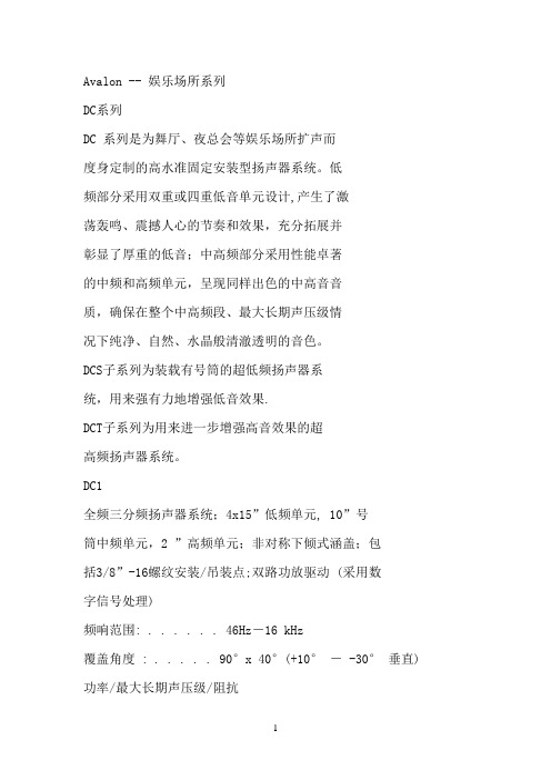
Avalon -- 娱乐场所系列DC系列DC 系列是为舞厅、夜总会等娱乐场所扩声而度身定制的高水准固定安装型扬声器系统。
低频部分采用双重或四重低音单元设计,产生了激荡轰鸣、震撼人心的节奏和效果,充分拓展并彰显了厚重的低音;中高频部分采用性能卓著的中频和高频单元,呈现同样出色的中高音音质,确保在整个中高频段、最大长期声压级情况下纯净、自然、水晶般清澈透明的音色。
DCS子系列为装载有号筒的超低频扬声器系统,用来强有力地增强低音效果.DCT子系列为用来进一步增强高音效果的超高频扬声器系统。
DC1全频三分频扬声器系统;4x15”低频单元, 10”号筒中频单元,2 ”高频单元;非对称下倾式涵盖;包括3/8”-16螺纹安装/吊装点;双路功放驱动 (采用数字信号处理)频响范围: . . . . . . 46Hz-16 kHz覆盖角度 : . . . . . 90°x 40°(+10°- -30°垂直) 功率/最大长期声压级/阻抗低频1: . . . . . . . . 1600W/129dB/4Ω低频2: . . . . . . . . 1600W/129dB/4Ω低频1+ 低频2: . .3200W/135dB/2Ω中频/高频: . . . . .350 W/133dB/8Ω连接: . . . . . . . . . . NL4和NL8 Speakon尺寸(mm): . . . . . 1016高x1770前/1133后宽x652深重量(kg): . . . . . . .182.3产品编号: . . . . . . .999968选件DC1系统悬吊杆将低频部分与中/高频部分固定为一体 , 每一DC1系统需要2个产品编号 . . . . . . . 179114DC2全频三分频扬声器系统;2x15”低频单元, 10”号筒中频单元,1.4 ”高频单元;配有3/8”-16螺纹安装/吊装点; 双路功放驱动 (采用数字信号处理)频响范围: . . . . . . 45 Hz - 18 kHz覆盖角度 : . . . . . .90° x 40°功率/最大长期声压级/阻抗低频: . . . . . . . . . 1600W/132dB/4Ω中频/高频: . . . . 350 W/133dB/8Ω连接: . . . . . . . . . . NL4 Speakon尺寸(mm): . . . . . 572前高/489后高x1449宽x483 深重量(kg): . . . . . . 86.4产品编号 . . . . . . . 999969DC3全频三分频扬声器系统;2x12”低频单元, 8”号筒中频单元,1”高频单元;配有3/8”-16螺纹安装/吊装点;双路功放驱动 (采用数字信号处理)频响范围: . . . . . . 50 Hz - 18 kHz覆盖角度 : . . . . . 90°x 40°功率/最大长期声压级/阻抗低频: . . . . . . . . . 800W/128dB/4Ω中频/高频: . . . . 250W/128dB/8Ω连接: . . . . . . . . . . NL4 Speakon尺寸(mm): . . . . . 476前/406后高x 1321宽 x406 深重量(kg): . . . . . . 54.5产品编号 . . . . . . .999970DC4全频三分频扬声器系统;2x12”低频单元, 8”中频单元1 ”高频单元;配有3/8”-16螺纹安装/吊装点;双路功放驱动 (采用数字信号处理)频响范围: . . . . . . . 45 Hz - 17.5kHz覆盖角度 : . . . . . . 90° x 40°功率/最大长期声压级/阻抗低频: . . . . . . . . . . .800W/128dB/4Ω中频/高频: . . . . . .220W/120dB/8Ω连接: . . . . . . . . . . . NL4 Speakon尺寸(mm): . . . . . . 486前/354后高 x959宽 x 508 深重量(kg): . . . . . . . .45产品编号 . . . . . . . . 999937DC5全频二分频扬声器系统;12”低频单元;1.4 ”高频单元;配有3/8”-16螺纹安装/吊装点;单路功放驱动频响范围: . . . . . . . .50 Hz - 18 kHz覆盖角度 : . . . . . . .90°x 45°功率/最大长期声压级/阻抗全频: . . . . . . . . . . 500W/124dB/8Ω连接: . . . . . . . . . . . NL4 Speakon尺寸(mm): . . . . . . 395前/306后高 x 762宽 x 346深重量(kg): . . . . . . . .29.5产品编号 . . . . . . . . 999972DC6全频二分频扬声器系统;2x8”低频单元, 1”高频单元;包括3/8”-16螺纹安装/吊装点;单路功放驱动频响范围: . . . . . . .50 Hz - 19 kHz覆盖角度 : . . . . . . 90° x 60°功率/最大长期声压级/阻抗全频: . . . . . . . . . . . 400W/121dB/4Ω连接: . . . . . . . . . . . NL4 Speakon尺寸(mm): . . . . . . 270前高/189后高x762宽x297深重量(kg): . . . . . . . .25.5kg产品编号 . . . . . . . . 997207D C S 系列EAW工程师发现,现代舞厅音乐的频谱具有这样一个特点:50Hz至60Hz低频段的声压级要比其他频段高出10-20dB。
UMC1000-产品更新说明
1.3.5 DOR416开关输出模块
36.0 7.5
C3-DIT316
25.0
单位:mm
② ① C3-DOR416
104.95
130.0
③
104.0 32.0
④
正面图
项目 ① ② ③ ④
侧面图
底部图
名称 电源指示灯 通讯指示灯 错误指示灯 输出指示灯
图1-12 DOR416模块
说明 指示电源状态,通电时常亮为绿色 通讯正常时为黄色闪烁 报错时为红色常亮 对应显示输入16路信号状态,满足输出时为绿色常亮
[T.OUT1] [T.OUT2]
VA VA
_ 11 ACU902模块输出信号可触发SSR固态继电器输出信
+
12
号,用户将固态继电器的直流输入部分的“+”接到
_ 13 温度输出端12,固态继电器的直流输入部分的“-”
+
接到温度输出端11,固态继电器的交流输出部分用户
14
应根据设备要求自行接线。
注:
1. 输出端的信号为12VDC信号,无需再接外部电源。
更新原因如下: 1) 增强模块的输入、输出抗干扰能力。 2) 增加PT100-2传感器类型,此传感器类型可测量至2位小数点。 3) 模块间的通讯方式改为总线通讯通讯。 4) 减少电源和模块配电。 5) 所有接线端子带有锁扣螺丝,增强端子的安全性。 6) 增强模块的扩展性。 7) 主输出、冷输出及变送输出的输出类型可在(Relay,SSR,4~20mA)间选择。 8) PID控制算法更新,增加抗超调抑制参数。 9) PID控制加热制冷双PID参数。 10)为之后推出的Chamber软件平台做硬件准备。
模块、DOR416开关输出模块)及GH5通讯电缆。
Maxsine EP100 系列 交流伺服驱动器 简明手册

MaxsineEP100系列交流伺服驱动器简明手册第1章产品检查与安装1.3 伺服电机安装1.3.1 安装环境条件●工作环境温度:0~40℃;工作环境湿度:80%以下(无结露)。
●贮存环境温度:-40~50℃;贮存环境湿度:80%以下(无结露)。
●振动:0.5G以下。
●通风良好、少湿气及灰尘之场所。
●无腐蚀性、引火性气体、油气、切削液、切削粉、铁粉等环境。
●无水汽及阳光直射的场所。
1.3.2 安装方法●水平安装:为避免水、油等液体自电机出线端流入电机内部,请将电缆出口置于下方。
●垂直安装:若电机轴朝上安装且附有减速机时,须注意并防止减速机内的油渍经由电机轴渗入电机内部。
●电机轴的伸出量需充分,若伸出量不足时将容易使电机运动时产生振动。
●安装及拆卸电机时,请勿用榔头敲击电机,否则容易造成电机轴及编码器损坏。
1.4 电机旋转方向定义本手册描述的电机旋转方向定义:面对电机轴伸,转动轴逆时针旋转(CCW)为正转,转动轴顺时针旋转(CW)为反转。
图1.2 电机旋转方向定义第2章接线2.1 配线规格●线径:R、S、T、PE、U、V、W端子线径≥1.5mm2(AWG14-16),r、t端子线径≥0.75mm2(AWG18);●端子采用预绝缘冷压端子,务必连接牢固;●建议采用三相隔离变压器供电;2.2 配线方法●输入输出信号线和编码器信号线,请使用推荐的电缆或相似的屏蔽线,配线长度为:输入输出信号线3m以下,编码器信号线20m以下。
接线时按最短距离连接,越短越好,主电路接线与信号线要分离。
●接地线要粗壮,作成一点接地,伺服电机的接地端子与伺服驱动器的接地端子PE务必相连。
●为防止干扰引起误动作,建议安装噪声滤波器,并注意:1) 噪声滤波器、伺服驱动器和上位控制器尽量近距离安装。
2) 继电器、电磁接触器、制动器等线圈中务必安装浪涌抑制器。
3) 主电路和信号线不要在同一管道中通过及不要扎在一起。
●在附近用强烈干扰源时(如电焊机、电火花机床等),输入电源上使用隔离变压器可以防止干扰引起误动作。
SSMB接插件
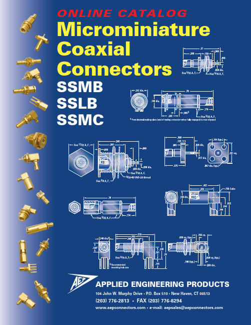
SSMBSSLBSSMCAPPLIED ENGINEERING PRODUCTS104 John W. Murphy Drive • P.O. Box 510 • New Haven, CT 06513Click at the bottom of any page to go to the AEP website.APPLIED ENGINEERING PRODUCTSIntroduction . . . . . . . . . . . . . . . . . . . . . . . . . . . . . . . . . . . . . . . . . . . . . . . . . . . . . . . . . . 2Technical InformationSpecial features and options. . . . . . . . . . . . . . . . . . . . . . . . . . . . . . . . . . . . . . . . . . . . . 3Mated-pair dimensions . . . . . . . . . . . . . . . . . . . . . . . . . . . . . . . . . . . . . . . . . . . . . . . . . 4Interfaces and specifications. . . . . . . . . . . . . . . . . . . . . . . . . . . . . . . . . . . . . . . . . . . . . 5VSWR data. . . . . . . . . . . . . . . . . . . . . . . . . . . . . . . . . . . . . . . . . . . . . . . . . . . . . . . . . . . 6SSMB SeriesCable connectors. . . . . . . . . . . . . . . . . . . . . . . . . . . . . . . . . . . . . . . . . . . . . . . . . . . . . . 7Bulkhead mounted receptacles. . . . . . . . . . . . . . . . . . . . . . . . . . . . . . . . . . . . . . . . . . . 9P .C. board receptacles . . . . . . . . . . . . . . . . . . . . . . . . . . . . . . . . . . . . . . . . . . . . . . . . . 10Panel mounted receptacles. . . . . . . . . . . . . . . . . . . . . . . . . . . . . . . . . . . . . . . . . . . . . 14Adapters . . . . . . . . . . . . . . . . . . . . . . . . . . . . . . . . . . . . . . . . . . . . . . . . . . . . . . . . . . . 14SSLB SeriesCable connectors. . . . . . . . . . . . . . . . . . . . . . . . . . . . . . . . . . . . . . . . . . . . . . . . . . . . . 15Vibration-proof float mount plugs. . . . . . . . . . . . . . . . . . . . . . . . . . . . . . . . . . . . . . . . 16Bulkhead mounted receptacles. . . . . . . . . . . . . . . . . . . . . . . . . . . . . . . . . . . . . . . . . . 17P .C. board receptacles . . . . . . . . . . . . . . . . . . . . . . . . . . . . . . . . . . . . . . . . . . . . . . . . . 18SSMC SeriesCable connectors. . . . . . . . . . . . . . . . . . . . . . . . . . . . . . . . . . . . . . . . . . . . . . . . . . . . . 20Bulkhead mounted receptacles. . . . . . . . . . . . . . . . . . . . . . . . . . . . . . . . . . . . . . . . . . 22P .C. board receptacles . . . . . . . . . . . . . . . . . . . . . . . . . . . . . . . . . . . . . . . . . . . . . . . . . 23Panel mounted receptacles. . . . . . . . . . . . . . . . . . . . . . . . . . . . . . . . . . . . . . . . . . . . . 27Adapters . . . . . . . . . . . . . . . . . . . . . . . . . . . . . . . . . . . . . . . . . . . . . . . . . . . . . . . . . . . 27P .C. Board Mounted Cable Terminations . . . . . . . . . . . . . . . . . . . . . . . . . . . . . . . . . . 28Index by AEP Part Number . . . . . . . . . . . . . . . . . . . . . . . . . . . . . . . . . . . . . . . . . . . . . 29About AEP . . . . . . . . . . . . . . . . . . . . . . . . . . . . . . . . . . . . . . . . . . . . . . . . . . . . . . . . . . 30Other AEP Product Lines . . . . . . . . . . . . . . . . . . . . . . . . . . . . . . . . . . . . . . . . . . . . . . . 31(Click on any line to jump to the page)SMB.237"SSMB P.C. BOARD SMA P.C. BOARD.625".510"Straight PCB receptacle and right angle cable plugComputer-controlled, automated solder-dipping equipment and custom fixturing ensure precise, consistent coverage to AEP standard specification (see above), P a n e lP.C. boardPanel P.C. boardPanelP a n e lC . b o a r dP.C. boardP.C. boardP.C. boardSolder(center conductor)Printed circuit boardSolder(bottom legs and center conductor)Printed circuit boardP .C. Board Receptacles with Standoff LegsPlugPlugClosed-entry contact accepts .014–.015 dia. pinClosed-entry contact accepts .014–.015 dia. pin.000 min..033 min..122 min.Specification requirement Actual(Connectors tested using 200' of cable as load.).53Hex 5/32 A. F..70Hex 5/32 A. F.AEP P/N .46Hex 5/32 A. F..63Hex 5/32 A. F.AEP P/N AEP P/NHex 5/32 A. F.16 A. F.§ Recommended mounting hole size,§ Recommended mounting hole size,Hex 5/32 A. F.16 A. F.16 A. F..386.140 dia.16 A. F..386.140 dia..126.150Hex 3.020 dia..140 dia.§ Recommended mounting hole size,.360Hex 16 A. F.§ Recommended mounting hole size,Hex 3/8 A. F..15016 A. F..036 dia..020 dia..140 dia.§§ Recommended mounting hole size,16 A. F..020 dia..156 sq.16 A. F..020 dia..156 sq..135.419.284.100 (typ.).038 sq. (typ.).156 sq..155.264.156 sq..026 dia..155.419.156 sq..026 dia..025.264.156 sq..026 dia..135.100 (typ.).100 (typ.).020 (typ.).156 sq..141.038 (typ.).080.026 dia.LEG FINISH AEP P/N16 A. F..126§.155.386§ Recommendedmounting hole size,.156 sq..026 dia.16 A. F..135.386.126§§ Recommendedmounting hole size,tolerance +.003, -.000.100 (typ.).038 sq. (typ.).156 sq..38616 A. F..025.126§§ Recommendedmounting hole size,tolerance +.003, -.000.156 sq..026 dia.16 A. F..126§.155.386§ Recommendedmounting hole size,tolerance +.003, -.000.156 sq..026 dia..100 (typ.)16 A. F..386§ .140 dia.16 A. F..386.135.100 (typ.).026 dia..140 dia.16 A. F..386mounting hole size, tolerance +.003, -.000.140 dia..126.038 (typ.).026 dia.16 A. F..386.141.140 dia..020 (typ.).156 sq..135.100 (typ.) .038 sq. (typ.).187dia..155.187dia..187 dia..026 dia..067 dia. (typ.).017 dia..375.125.067 dia. (typ.).026 dia..017 dia..360Hex 5/§ Recommended mounting hole size,16 A. F..360Hex 5/16 A. F.§ Recommended mounting hole size,.53Hex 5/32 A. F..70Hex 5/32 A. F.AEP P/NHex 5/32 A. F.16 A. F.§ Recommended mounting hole size,§ Recommended mounting hole size,Hex 5/32 A. F.16 A. F.§.06516 A. F..020 dia..156 sq..360Hex 16 A. F.§ Recommended mounting hole size,Hex 3/8 A. F.16 A. F..020 dia..156 sq..15016 A. F..036 dia..020 dia..140 dia.§ Recommended mounting hole size,.135.419.284.100 (typ.).038 sq. (typ.).156 sq..155.264.156 sq..026 dia..155.419.156 sq..026 dia..025.264.026 dia..135.100 (typ.).100 (typ.).141.020 (typ.).156 sq..038 (typ.).080.026 dia.LEG FINISH AEP P/N.135.337.100 (typ.).038 sq. (typ.).187 dia..155.317.187 dia..187 dia..026 dia..70Hex 5/32 A. F.AEP P/N .46Hex 5/32 A. F..63Hex 5/32 A. F.AEP P/N AEP P/N Hex 5/32 A. F..19Hex 5/32 A. F..360§ Recommended mounting hole size,16 A. F.Hex 5/32 A. F..360§ Recommended mounting hole size,16 A. F.16 A. F..386.140 dia.16 A. F..386.140 dia..150Hex 3.020 dia..140 dia.§ Recommended mounting hole size,.360Hex 16 A. F.§ Recommended mounting hole size,.135.419.284.100 (typ.).038 sq. (typ.).156 sq..155.264.156 sq..026 dia..155.419.156 sq..026 dia..025.264.156 sq..026 dia..135.100 (typ.).100 (typ.).100 (typ.).038 (typ.).080.026 dia./16 A. F..126§.155.386§ Recommended mounting hole size,tolerance +.003, -.000.156 sq..026 dia.16 A. F..135.386.126§§ Recommendedmounting hole size,tolerance +.003, -.000.100 (typ.).038 sq. (typ.).156 sq..38616 A. F..025.126§§ Recommendedmounting hole size,tolerance +.003, -.000.156 sq..026 dia.16 A. F..126§.155.386§ Recommendedmounting hole size,tolerance +.003, -.000.156 sq..026 dia.16 A. F..386§ .140 dia..100 (typ.).386§ .126.13516 A. F..100 (typ.).026 dia..140 dia..38616 A. F..140 dia..126.038 (typ.).026 dia..386.14116 A. F..140 dia..020 (typ.).156 sq..155 .317.187 dia.Hex 5/(P.C. board thickness).472Hex 5/32 A. F..375.125.017 dia..067 dia. (typ.).375.125.067 dia. (typ.).026 dia..017 dia..360Hex 5/§ Recommended mounting hole size,16 A. F..360Hex 5/§ Recommended mounting hole size,16 A. F..135.314.100 (typ.).038 sq. (typ.).156 sq..155.294.156 sq..026 dia..155.45.156 sq..026 dia..135.100 (typ.).026 dia..100 (typ.).141.020 (typ.).156 sq..038 (typ.).080.026 dia.LEG FINISH AEP P/NAPPLIED ENGINEERING PRODUCTS • aepsales@ 29Index by Part NumberP/N P a g e 5011-1503-000. . . . . . . . .14 5013-1503-000. . . . . . . . .27 5937-1503-000. . . . . . . . .14 5938-1503-000. . . . . . . . .27 7002-1541-0X X*. . . . . . . .20 7002-1571-0X X*. . . . . . . .20 7003-1542-0X X*. . . . . . . .21 7003-1572-0X X*. . . . . . . .21 7004-1512-000. . . . . . . . .22 7009-1511-000. . . . . . . . .23 7009-1511-004. . . . . . . . .23 7009-1511-005. . . . . . . . .23 7009-1511-040. . . . . . . . .23 7009-1511-041. . . . . . . . .23 7009-1511-050. . . . . . . . .23 7009-1511-061. . . . . . . . .23 7010-1511-000. . . . . . . . .23 7010-1511-015. . . . . . . . .23 7010-1511-040. . . . . . . . .23 7010-1511-041. . . . . . . . .23 7010-1511-050. . . . . . . . .23 7010-1511-060. . . . . . . . .23 7010-1511-061. . . . . . . . .23 7012-1511-000. . . . . . . . .22 7017-1512-000. . . . . . . . .22 7022-1502-000. . . . . . . . .14 7022-1502-000. . . . . . . . .27 7025-1512-000. . . . . . . . .26 7025-1512-012. . . . . . . . .26 7025-1512-015. . . . . . . . .26 7025-1512-040. . . . . . . . .26 7025-1512-050. . . . . . . . .26 7025-1512-060. . . . . . . . .26 7025-1512-061. . . . . . . . .26 7029-1511-000. . . . . . . . .24 7029-1511-012. . . . . . . . .24 7029-1511-015. . . . . . . . .24 7029-1511-015. . . . . . . . .24 7029-1511-040. . . . . . . . .24 7029-1511-060. . . . . . . . .24 7029-1511-061. . . . . . . . .24 7040-1511-000. . . . . . . . .22 7042-1511-000. . . . . . . . .26 7042-1511-012. . . . . . . . .26 7042-1511-015. . . . . . . . .26 7042-1511-040. . . . . . . . .26 7042-1511-050. . . . . . . . .26 7042-1511-060. . . . . . . . .26 7042-1511-061. . . . . . . . .26 7101-1541-0X X*. . . . . . . .20 7101-1571-0X X*. . . . . . . .20 7105-1521-0X X*. . . . . . . .20 7105-1561-0X X*. . . . . . . .20 7106-1521-0X X*. . . . . . . .21 7106-1561-0X X*. . . . . . . .21 7110-1511-000. . . . . . . . .25 7110-1511-012. . . . . . . . .25 7110-1511-015. . . . . . . . .25 7110-1511-040. . . . . . . . .25 7110-1511-050. . . . . . . . .25 7110-1511-060. . . . . . . . .25 7110-1511-061. . . . . . . . .25 7119-1512-000. . . . . . . . .22P/N P a g e7122-1502-000. . . . . . . . .277141-1562-0X X*. . . . . . . .217141-1572-0X X*. . . . . . . .217145-1511-0X X*. . . . . . . .287145-1511-1X X*. . . . . . . .287145-1511-2X X*. . . . . . . .287145-1511-3X X*. . . . . . . .287145-1511-4X X*. . . . . . . .287145-1511-5X X*. . . . . . . .287145-1511-6X X*. . . . . . . .287146-1511-0X X*. . . . . . . .287146-1511-1X X*. . . . . . . .287146-1511-2X X*. . . . . . . .287146-1511-3X X*. . . . . . . .287146-1511-4X X*. . . . . . . .287146-1511-5X X*. . . . . . . .287198-1513-000. . . . . . . . .277199-1513-000. . . . . . . . .277201-1541-0X X*. . . . . . . .77201-1571-0X X*. . . . . . . .77202-1542-0X X*. . . . . . . .77202-1572-0X X*. . . . . . . .77203-1541-0X X*. . . . . . . .87203-1571-0X X*. . . . . . . .87204-1511-000. . . . . . . . . .97209-1511-000. . . . . . . . .107209-1511-011. . . . . . . . .107209-1511-015. . . . . . . . .107209-1511-023. . . . . . . . .107209-1511-040. . . . . . . . .107209-1511-061. . . . . . . . .107210-1511-000. . . . . . . . .107210-1511-015. . . . . . . . .107210-1511-040. . . . . . . . .107210-1511-050. . . . . . . . .107210-1511-060. . . . . . . . .107210-1511-061. . . . . . . . .107212-1511-000. . . . . . . . . .97217-1512-000. . . . . . . . . .97219-1511-000. . . . . . . . . .97222-1501-000. . . . . . . . .147225-1512-000. . . . . . . . .137225-1512-012. . . . . . . . .137225-1512-015. . . . . . . . .137225-1512-040. . . . . . . . .137225-1512-050. . . . . . . . .137225-1512-060. . . . . . . . .137225-1512-061. . . . . . . . .137229-1511-000. . . . . . . . .117229-1511-012. . . . . . . . .117229-1511-015. . . . . . . . .117229-1511-040. . . . . . . . .117229-1511-050. . . . . . . . .117229-1511-060. . . . . . . . .117229-1511-061. . . . . . . . .117240-1511-000. . . . . . . . . .97242-1511-000. . . . . . . . .137242-1511-012. . . . . . . . .137242-1511-015. . . . . . . . .137242-1511-040. . . . . . . . .137242-1511-050. . . . . . . . .137242-1511-060. . . . . . . . .137242-1511-061. . . . . . . . .13P/N P a g e7302-1542-0X X*. . . . . . . .157302-1572-0X X*. . . . . . . .157303-1541-0X X*. . . . . . . .167303-1571-0X X*. . . . . . . .167304-1511-000. . . . . . . . .177305-1521-0X X*. . . . . . . .157305-1561-0X X*. . . . . . . .157309-1511-000. . . . . . . . .187309-1511-012. . . . . . . . .187309-1511-015. . . . . . . . .187309-1511-040. . . . . . . . .187309-1511-050. . . . . . . . .187309-1511-060. . . . . . . . .187309-1511-061. . . . . . . . .187310-1511-000. . . . . . . . .187310-1511-012. . . . . . . . .187310-1511-015. . . . . . . . .187310-1511-040. . . . . . . . .187310-1511-050. . . . . . . . .187310-1511-060. . . . . . . . .187310-1511-061. . . . . . . . .187312-1511-000. . . . . . . . .177317-1511-000. . . . . . . . .177325-1512-000. . . . . . . . .197325-1512-012. . . . . . . . .197325-1512-015. . . . . . . . .197325-1512-040. . . . . . . . .197325-1512-050. . . . . . . . .197325-1512-060. . . . . . . . .197325-1512-061. . . . . . . . .197332-1571-0X X*. . . . . . . .167332-1571-2X X*. . . . . . . .167335-1571-0X X*. . . . . . . .167335-1571-2X X*. . . . . . . .167340-1511-000. . . . . . . . .177341-1561-0X X*. . . . . . . .157341-1571-0X X*. . . . . . . .157342-1511-000. . . . . . . . .197342-1511-012. . . . . . . . .197342-1511-015. . . . . . . . .197342-1511-040. . . . . . . . .197342-1511-050. . . . . . . . .197342-1511-060. . . . . . . . .197342-1511-061. . . . . . . . .197396-1512-000. . . . . . . . .177405-1521-0X X*. . . . . . . .77405-1561-0X X*. . . . . . . .77406-1521-0X X*. . . . . . . .87406-1561-0X X*. . . . . . . .87410-1511-000. . . . . . . . .127410-1511-012. . . . . . . . .127410-1511-015. . . . . . . . .127410-1511-040. . . . . . . . .127410-1511-050. . . . . . . . .127410-1511-060. . . . . . . . .127410-1511-061. . . . . . . . .127441-1561-0X X*. . . . . . . .87441-1571-0X X*. . . . . . . .87496-1512-000. . . . . . . . . .97498-1513-000. . . . . . . . .147499-1513-000. . . . . . . . .14* Indicates cable connectors with varioustypes on specified page.(Click on any line to jump to the page)(203) 776-2813 • FAX (203) 776-8294APPLIED ENGINEERING PRODUCTS • aepsales@ 30About Applied Engineering ProductsSince our foundation in 1973, we have always believed that having our customers take a look “inside AEP” is important in fostering strong vendor/customer relationships. We are proud of our physical plant and equipment, but even more so of our dedicated staff. When customers see first-hand how AEP’s people keep a constant focus on maintaining and improvingcustomer service and satisfaction, the rea-son for our consistently strong on-timedelivery and quality records becomes clear.We invite you to see for yourself. Call us toarrange a plant tour—or, if you can’t makea visit, ask for your copy of INSIDE AEP,our facilities and capabilities brochure.(203) 776-2813 • FAX (203) 776-829431The SSMB, SSLB, and SSMC connectors in this brochure are only part of our complete line of subminiature coaxial connectors and cable assemblies, including:• MCX• MMCX• SMA• SMB• SMC• SSMA• SSMB• SSMC• SLB (Slide-on version of SMB)• SSLB (Slide-on version of SSMB)• 75ΩMiniature SMB• 75ΩSnap-on mating• 75ΩScrew-on mating• Adapters within and between series• Flexible cable assemblies• Semi-rigid cable assemblies• And over 100 styles of MIL-PRF-39012 QPL connectorsin series SMA, SMB, and SMCAPPLIED ENGINEERING PRODUCTS104 John W. Murphy Drive • P .O. Box 510 • New Haven, CT 06513(203) 776-2813• FAX (203) 776-8294 • e-mail: aepsales@。
Delta_ASDA-A2_M_SC_20130603操作手册-第三章 配线

伺服电机
Revision Jun, 2013
3-1
第三章 配线ASDA-A2 系列
NOTE
安装注意事项: 1) 检查 R、S、T 与 L1c、L2c 的电源和接线是否正确。 2) 确认伺服电机输出 U、V、W 端子相序接线是否正确,接错电机可能 不转或乱转。 D 端开路、 外部回生电阻应接于 P 、 3) 使用外部回生电阻时, 需将 P 、 C 端,若使用内部回生电阻时,则需将 P 、D 端短路且 P 、C 端开 路。 4) 异警或紧急停止时, 利用 ALARM 或是 WARN 输出将电磁接触器 (MC) 断电,以切断伺服驱动器电源。
3-2
Revision Jun, 2013
第三章 配线ASDA-A2 系列
3.1.2 驱动器的连接器与端子
端子记号
L1c、L2c R、S、T U、V、W FG
名称
控制回路电源输入端 主回路电源输入端 电机连接线 格)
说明
连接单相交流电源。 (根据产品型号,选择适当的电压规 连接三相交流电源。 (根据产品型号,选择适当的电压规 格) 连接至电机 端子记号 U V W FG 线色 红 白 黑 绿 连接至驱动器的接地处 P 、D 端短路,P 、C 端开路 电阻接于 P 、C 两端,且 P 、D 端开路 使用外部刹车单元 将刹车单元的 P 、P 分别连接于 伺服的 P 、P 两端,且 P 、D -8
Revision Jun, 2013
第三章 配线ASDA-A2 系列
3.1.5 编码器引出线的连接头规格
编码器连接示意图一:
伺服驱动器
*2
快速接头
*1
CN2 连接头
编码器引出线 的连接头
编码器引出线
电机
MR_J2_CT(1)
!
伺服电机的电磁制动器用于保持,不用作通常情况下的制动。
!
电磁制动器因寿命及机械结构(通过同步皮带将滚珠丝杠和伺服电机连接在一起时等)的原因可能出现 无法保持的情况。为确保设备安全请安装停止装置。
(5)异常时的处理
! 注意
!
为防止设备停止运转或发生故障时可能发生的危险,作为保持请使用带有电磁制动器的伺服电机或安装 外部制动装置。
请勿用湿手操作开关。否则可能导致触电。
请勿使电缆受损或以重物挤压电缆。否则可能导致触电。
2. 火灾防范
! 注意
请将伺服驱动单元、伺服电机、回生电阻安装在非可燃物上。直接安装于可燃物上或接近可燃物均可能 引发火灾。
伺服驱动单元的电源输入,请务必按照本说明书的指示安装无熔丝断路器及接触器。请参照本说明书正 确选用无熔丝断路器及接触器。误用可能引发火灾。
(请参阅“第 3 章 安装”) 必要时,请在强电柜内部安装风扇,有助于驱动单元上部散热。在以下安装条件下进行的温度测试,需通过风扇
1
安全使用指南 1. 触电防范
实施接线作业、设备检查时,必须关闭电源。待电源关闭 10 分钟后,充电指示灯熄灭,用万用表等确认 P-N 端子间的电压,然后再进行作业。否则可能导致触电。 伺服驱动单元及伺服电机必须实行第 3 种以上的接地措施。 接线作业、设备检查必须由专业技术人员进行。
伺服驱动单元及伺服电机,在装配完成后方可进行接线。否则可能导致触电。
使用标准中包含与 EN 规格对应的产品、 EN 规格对应品。
电机系列名 HC-SF 系列 HC-RF 系列 HA-FF 系列
HC-MF 系列
EN 规格对应品
对应的标准品
HA-FF**C-UE HC-MF**-UE HC-MF**-S15
PIAB
PIAB真空发生器库存型号:Vacuum pump M10A5-AN @Vacuum pump X40B6ADN PMAT COAX pump unti low prof.0106829 Suction cup F75P.5K @Vacuum pump X40B6ADNA VacTrap VT-1A (3/8 0111594 F75P @Vacuum pump X80B6ADN VacTrap VT-1AGM (3/8 120576 @Vacuum pump X80B6ADNA VacTrap VT-1AS with COAX 0100372 Vacuum pump M50B6-DN @Vacuum pump X120B6ADN VGS3010 Check valvePIAB样品盒. @Vacuum pump X120B6ADNA Suction cupD30-2.10.02CD8BR31E00G\n8BL31J50G\n8BF31J10G @Vacuum pump H40B6ADN Suction cupBL40-2.10.04CADP082406SEN @Vacuum pump H40B6ADNA Suction cupD20-2.10.02CDDP162425SEN @Vacuum pump H120B6ADN Suction cupU40-2.30.04CAGasket kit Round pump @Vacuum pump H120B6ADNA Suction cup B20 cpl. Gasket kit Round pump @Vacuum pump M25B5ADN Suction cup F20.10.02CD100197 @Vacuum pump M25B5ADNA Suction cupBL30-2.10.04CA0100215 H120B6-DVA @Vacuum pump M50B5ADN Suction cupF50-2.30.05CA100366 @Vacuum pump M50B5ADNA Suction cup U20.10.02CD0100372 Vacuum pump M50B6-DN @Vacuum pump M100B5ADN Suction cupB50-2.30.05CA100378 @Vacuum pump M100B5ADNA Suction cupBL50-2.10.05CA0100411 X40F6-KN @Manifold profile 1x2G AVP BX75P 2 Rail Gasket kit MiniFlex 20-60 @Manifold profile 2x2G AVP BX75P 4 Rail Gasket kit MidiFlex 160-320 @Connection plate G3/4 AVP BX75P 6 Rail Gasket kit Midi 160-320 @Connection plate 3/4 AVP BX110P 2 Rail 100563 @Housing Maxi L200 cpl. AVP BX110P 4 RailStrenghtening ring 20-30 Silic @Housing Maxi L400 cpl. AVP BX110P 6 RailStrengthening ring 40 Silicone @Housing Maxi L800 cpl. VacTrap & COAX with lock-pin 1Strengthening ring 50 Silicone @Housing Maxi L1200 cpl. VacTrap VT-1AMGM x-drilled/mou101101 @Housing Maxi L1600 cpl. @VacTrap VT-1A (3/8101102 @Vacuum pump M25B6ADN @Locking device AVR BX75P-BX110101103 @Suction cup D20-2, 500 pcs. @Lateral support 87mm w. print101105 @Suction cup B75.30.W, 250pcs.@Lateral support 126mmw.print0101107 Suction cup B50.30 @Suction cup B10-2.20, 1000pcs@Side plate PIAB0101109 Suction cup B50-2.30 @Suction cup B15-2.10, 1000pcs@Support beam 500 AVRBX75P-BX10101110 Suction cup B50-2.20 @Suction cup B50-2.30 filt.500@AQR vavle101111 @Suction cup B10-2.10, 1000pcs@Profile 45x90L L4004xM120101123 Suction cup D20-2.10 @Suction cup B75-2.30.W 250pcs@Profile 45x90L L8004xM12101129 @Vacuum pump L25B6-DV @Profile 45x90L L1200 4xM120101131 Suction cup F25.10 @Vacuum pump L25B6-DVA@*111537 Conveyor IC3301F30-2.10 0101133 @Vacuum pump L50B6-DE @Mounting kit Level compensator LC300101135 Suction cup F40-2.30 @Vacuum pump L50B6-DV @Level compensator LC30 cpl.0101137 Suction cup F50.2.30 @Vacuum pump L50B6-DVA @Suction cup F75P.4E101140 @Vacuum pump L100B6-DE @Suction cup F75P.4E.07NA0101144 U20 @Vacuum pump L100B6-DEA @Suction cupF75P.4E.07ND101146 @Vacuum pump L100B6-DV @Suction cup F75P.4E.07NE101147 @Vacuum pump L100B6-DVA @Suction cup F75P.4E.07NF101150 @Vacuum pump M25B5-DE @Spare part kit LC30 0101152 Fitting 20-30 02AF @Vacuum pump M25B5-DV @Suction cup F110P.4E 0101153 Fitting 40 04AG @Vacuum pump M50B5-DEA @Suction cup B75P.4E0101154 Fitting 50 05AG @Vacuum pump M50B5-DV @Suction cup F110P.4E.11NA0101176 Suction cup B20.20.02AF @Suction cup B20.20, 500pcs.@Suction cupF110P.4E.11NB101205 @Suction cup B15-2.20, 1000pcs@Suction cupF110P.4E.11NCSuction cup D20-2.10.02AB @Housing M50B6 V @Suction cup B75P.4E.07NA101238 @Housing M50B5 E @Suction cup B75P.4E.07ND101264 @Interm. housing M50B6 V @Suction cup B75P.4E.07NESuction cup F20.10.02DB @Sideplate AD V @Suction cup B75P.4E.07NF101275 @Valve plate M V A @Suction cupBL40-3P.4L.04AJ101326 @Vacuum pump X20F6-TN @Silencer Mini Coax 101330 @Vacuum pump X30F6-TN @Silencer Midi Coax101423 @Vacuum pump X20F5-TN @Vacuum rail10x1C-M10L-BX52-1200101435 @Vacuum pump X30F5-TN @Cable L=3m, M16 8-pin straight0101436(5PCS起订) @Vacuum pump M20F6-TN @Cable L=3m, M16 8-pin angled101462 @Vacuum pump M30F6-TN@*0112413 Demo Case vacuum pump P60100101569(F40-2.30.04AD) @Suction cup B50-2.30.05AA500 pcs@Spare parts P6010101572 @Suction cup F25, 500 pcs. @Sealing gable Midi COAX 101636 @Adapter kit Classic-MLD @Silencer 1Suction cup B50.30.05AG @Vacuum Control Box, CB 01,copal@Blind Cartridge Midi-30101727 D50吸盘@Suction cup U15.10 1000PCs.@Vacuum gauge 100 -kPaSuction cup F50-2.30.05AB @Suction cup B-BL40-2 500pcs.@Manometer 1 MPa0101850 吸盘@Vactivator V10/45 @Manometer 250 kPa 0101854 B75吸盘@Suction cup BF80P.4H.08UA @PCC 01 EV, Vacuum 101858 @Suction cup BF80P.4H.08UB @PCC 01 EB, Blow0101874 Suction Cup F75.30.07ND @Suction cupOC35x90P.4C.39UA@Control unit AVM 001 NO30/500101884 吸盘@Suction cupOC35x90P.4C.39UB@Control unit AVM 001 NO30/700101890 B110吸盘@Suction cup B110.30.11UA250 p@Control unit AVM 001 NO50/700101914 整体吸盘@Suction cup B20 500 pcs. @Control unit AVM 001 NC 30/500101915 Suction Cup F110.30.11NA @Suction cup D20-2.20, 500pcs.@Control unit AVM 001 NC30/700101938(F150) @Suction cup B20 copal, 500PCs.,@Control unit AVM 001 NC50/70M50B5-ENA @Vacuum pump H40B6-ENA @Valve unit P6010M100B5-ENA @Vacuum pump H120B6-ENA @Fitting 40 04AJ, G3/8 0102113 M50B6ADN @Vacuum pump M50B5-ENA @Suction cup BL40-3P.4L0102119 /L50B6ADN @Panel sideplate 3/4 @Filter and O-rings for PCC102133 @Vacuum pump M20F6-TNA @Fitting 40 04AL, 3/8102135 @Vacuum pump M20F6-TE @Suction cupBL40-3P.4L.04AL102137 @Vacuum pump M20F6-TEA @Valve unit VU EP-1 0102761 M10A5-CN @Vacuum pump M30F6-TNA @Housing P60100102789 M20F5-TN @Vacuum pump M30F6-TE @Cartridge Module Blind X4102805 @Vacuum pump M30F6-TEA @Cartridge Module Si32-3X1Vacuum pump M20A5-B1N @Vacuum pump X20F6-TNA @Cartridge Module Si32-3X20102853 L7A6-AN @Vacuum pump X20F6-TE @Cartridge Module Si32-3X30102865 真空发生器@Vacuum pump X20F6-TEA @Cartridge Module Si32-3X4103061 @Vacuum pump X30F6-TNA @Cartridge Module Si32-3X1, A103109 @Vacuum pump X30F6-TE @Cartridge Module Si32-3X2, A103203 @Vacuum pump X30F6-TEA @Cartridge Module Si32-3X3, A103296 @Vacuum pump X20F5-TNA @Cartridge Module Si32-3X4, A103299 @Vacuum pump X20F5-TE @Cartridge Module Pi48-3X10103879 Pump unit Maxi L400真空发生器@Vacuum pump X20F5-TEA @Cartridge Module Pi48-3X20103884/1 Connection unit 33/26,D=76,NBR 进料部分@Vacuum pump X30F5-TNA@Cartridge ModulePi48-3X30103890/1 3302 Gore Sinbran filter unit,NBR 过滤部分@Vacuum pump X30F5-TE@Cartridge ModulePi48-3X40103915/1 Bottom value unit 33/34,fluid,NBR,AL 底阀@Vacuum pump X30F5-TEA@Cartridge ModulePi48-3X1, A0103919 Control unit Cu-1B,Normal Colse,with mounting bracket 控制器@Valve 3/2 G1/8@Cartridge ModulePi48-3X2, A0103930 Nylon tubing Kit Cu-C33,Fluid 连接器@Suction cup BL20-2,Silicone 500 pcs@Cartridge ModulePi48-3X3, A0104162 M200B5-VN cpl @Suction cup F30-2, 500 pcs. @Cartridge Module Pi48-3X4, A104274 @Vacuum pump M40F6-TN @Mounting T-slot, Cover plate labelled104284 @Suction cupBL50-2.10.05AB, 500 pcs@Cover plate G-con.,Cover plate plain104315 @Suction cup B10-2.10.01AC1000 pcs@Function PCC, Coverplate G connections106200 @Suction cup F15.10, 1000pcs.@Function AVM NO30/50,Cover plate G con.PNP30-KPA 真空发生器@Suction cup B50-2 filtercpl,@Function AVM NO30/70,Cover plate G con.106619 @Suct.cup B50-2 filter cpl500 pcs@Function AVM NO50/70,Cover plate G con.106676 @Level compensator G1/8 @Function AVM NC30/50, Cover plate G con.106895 @Suction cupF75.20 250-pcs@Function AVM NC30/70,Cover plate G con.0107321 B75P @Valve kit, Kalrez @Function AVM NC50/70, Cover plate G con.108141 @Lab Vac H80K6-REAC @Cover plate Classic G, Cover plate plain0109006 Suction cup BX25P.4K @Lab Vac H80K6-RVAC @Cover plate NPSF con., Cover plate plain110238 @Suction cup B20.20.02AD,500 pcs@Cover plate ClassicNPSF, Cover p. plain0110245 PNP30-KPA @Suction cup U20 Silicone500 pcs@Function AVM NO30/70,Cover plate NPSF110307 @Suction cup F20 500-pack @Function AVM NO30/50, Cover plate NPSF0112495\n @Suction cup F25.10, 500pcs.@Function AVM NO50/70,Cover plate NPSF115344 @Vactivator V10/20 @Function AVM NC30/50, Cover plate NPSF116971 @Suction cup B40 Silicone @Function AVM NC30/70,500 pcs Cover plate NPSF117611 @Fitting 20-30 Al. cpl. 500pcs@Function AVM NC50/70,Cover plate NPSF0118445 P5010 @Fitting 40 cpl. 500 pcs. @Function PCC blow, Cover plate G conn.0118446 P5010演示盒@Suction cup F40-2 500 pcs. @Function PCC blow, Cover plate NPSF conn118724 @Duo valve 12 @Function PCC vacuum, Cover plate NPSF122881 @Vacuum chip L7 model 1 @Connections 2x G 1 122882 @Vacuum chip L14 model 1 @Connections 2x G1 122884 @Vacuum chip L14 model 2 @Connections 2x G3/4122896 @Vacuum chip M5L model 1 @Connections 2x G3/4, silencer122898 @Vacuum chip M10L model 1 @Connections 2x 1 0124506 piGRIP样品包@Vacuum chip M10L model 2 @Connections 2x 1 0124515 BL30-5.20.04AZ @Vacuum chip L7A6-ZN @Connections 2x 3/4 Valve DI82406SE @Vacuum chip L7A6-ZNA @Connections 2x 3/4 Valve DI82406SD @Vacuum chip L14A6-ZN 31.01.613DP082406SEN @Vacuum chip L14A6-ZNA Remote valve G1/2 excl filter housingDP162425SEN @Vacuum chip M5A5-ZN Silencer inner MLL200-400 cpl.Valve DP232425SEN @Vacuum chip M5LA5-ZNA @Silencer outer MLL200-400 cpl.Valve DP082406SDN @Vacuum chip M10A5-ZN @Silencer inner MLL800 cpl.Valve DP162425SDN @Vacuum chip M10LA5-ZNA @Silencer outer MLL800 cpl.Valve DP232425SDN @Vacuum pump L7A6-CN @Silencer inner MLL1200 cpl.Vacuum pump X40H6-O @Vacuum pump L7A6-CNA @Silencer outer MLL1200 cpl.Vacuum pump X40H6-P @Vacuum pump L14A6-CN @Panel MLL200/400 cpl. Valve DG162425SE @Vacuum pump L14A6-CNA @Panel MLL800 cpl.Valve DG162425SD @Vacuum pump L28A6-CN @Panel MLL1200 cpl. Vacuum pump M50B6-EEA @Vacuum pump L28A6-CNA @Vacuum pump MLL200 Vacuum pump M100B6-EE @Vacuum pump M5A5-CN @Vacuum pump MLL200 Vacuum pump M100B6-EV @Vacuum pump M5A5-CNA @Vacuum pump MLL400 Vacuum pump X40B6-DN @Vacuum pump M10A5-CN @Vacuum pump MLL400 Vacuum pump X40B6-DV @Vacuum pump M10A5-CNA @Vacuum pump MLL400 Vacuum pump X40B6-DNA @Vacuum pump M20A5-CN @Vacuum pump MLL800 Vacuum pump X40B6-DVA @Vacuum pump M20A5-CNA @Vacuum pump MLL800 Vacuum pump X80B6-DN @Vacuum pump M20A5-CE @Vacuum pump MLL800 Vacuum pump X80B6-DE @Vacuum pump L14F6-TN @Vacuum pump MLL1200 Vacuum pump X80B6-DV @Vacuum pump L14F6-TNA @Vacuum pump MLL1200 Vacuum pump X80B6-DNA @Vacuum pump L28F6-TN @Vacuum pump MLL1200 Vacuum pump X120B6-DN @Vacuum pump L28F6-TNA @Gasket kit MLL200/400 Vacuum pump X120B6-DE @Vacuum pump M10F5-TN @Gasket kit MLL200/400 Vacuum pump X120B6-DV @Vacuum pump M10F5-TNA @Gasket kit MLL200/400 Vacuum pump X120B6-DNA @Vacuum pump M20F5-TN @Gasket kit MLL800 Vacuum pump X120B6-DEA @Vacuum pump M20F5-TNA @Gasket kit MLL800 Vacuum pump X120B6-DVA @Vacuum pump M30F5-TN @Gasket kit MLL800 Gasket kit Round pump @Vacuum pump M30F5-TNA @Gasket kit MLL1200 Vacuum pump X40B6-EN @Vacuum pump L56F6-KN @Gasket kit MLL1200 Vacuum pump X40B6-EV @Vacuum pump L56F6-KNA @Inlet gauze MLL200-400 Vacuum pump X120B6-EN @Vacuum pump M40F5-KN @Inlet gauze MLL800-1600 Vacuum pump X120B6-EE @Vacuum pump M40F5-KNA @Inlet gasket MLL200-400@Vacuum pump X120B6-EV @Vacuum pump M60F5-KN @Inlet gask. MLL200-400 EPDM@Vacuum pump X120B6-ENA @Vacuum pump M60F5-KNA @Inl.gasket MLL200-400 Viton@Vacuum pump H40B6-DN @Vacuum pump L7A6-B1N @Inlet gasketMLL800-1600@Vacuum pump H40B6-DE @Vacuum pump L7A6-B1NA @Inl.gasket MLL800-1600 EPDM@Vacuum pump H40B6-DV @Vacuum pump L14A6-B1N @Inl.gasket MLL800-1600 Viton@Vacuum pump H40B6-DNA @Vacuum pump L14A6-B1NA @Sidepl gasket MLL200-1600@Vacuum pump H40B6-DEA @Vacuum pump L28A6-B1N @Sidep.gask. MLL200-1600 EPDM@Vacuum pump H40B6-DVA @Vacuum pump L28A6-B1NA @Sidep.gask. MLL200-1600 Viton@Vacuum pump H120B6-DN @Vacuum pump M5A5-B1N @Sideplate right MLL200-1600@Vacuum pump H120B6-DE @Vacuum pump M5A5-B1NA @Sideplate left MLL200-1600@Vacuum pump H120B6-DV @Vacuum pump M10A5-B1N @Flap valve 148@Vacuum pump H120B6-DNA @Vacuum pump M10A5-B1NA @Flap valve 148 EPDM@Vacuum pump H120B6-DEA @Vacuum pump M20A5-B1N @Flap valve 148 Viton@Vacuum pump H40B6-EV @Vacuum pump M20A5-B1NA @Flap valve 300@Vacuum pump H120B6-EV @Vacuum pump L7A6-AN @Panel holder 148@Logics M5 female plug @Vacuum pump L7A6-ANA @Panel holder 300@Logics 2 x D=5 plug @Vacuum pump L14A6-ANA @Flap valve OF@Logics 2 x D=5 @Vacuum pump M5A5-AN @Flap valve OF, EPDM@Logics G1/8 @Vacuum pump M5A5-ANA @Flap valve OF Kalrez@Logics M5 male @Vacuum pump M10A5-AN @Flap valve OF Silicone @Logics 1/8 @Vacuum pump M10A5-ANA @Flap valve L63-125 Viton @Cover plate 1 ss @Vactivator kit V10/45-L14 @Non return valve OF@Fitting 20-30 02AE @Spare part kit V10/45 @Non return valve OF@Fitting 40 04AF @Spare part kit V10/20 @Non return valve OF@Fitting 50 05AF @Connection plate B1 cpl. @Flap valve 400@Cover plate 2 ss @Connection plate B2, cpl. @Flap valve 400 EPDM@Panel Classic @Vacuum pump L7A6-BN @Flap valve 400 Vitone@Vacuum pump M25B6-DN @Vacuum pump L7A6-BNA @Vacuum gauge 250,conn. down@Vacuum pump M25B6-DE @Vacuum pump L14A6-BN @Vacuum gauge w. nut -100kPa/-3@Vacuum pump M25B6-DV @Vacuum pump L14A6-BNA @Manometer with nut 1MPa/140 psi@Vacuum pump M25B6-DNA @Vacuum pump L28A6-BN @Vacuum gauge-100kPa/-30 inHg@Vacuum pump M25B6-DEA @Vacuum pump L28A6-BNA @Manometer 1 MPa/140 psi @Vacuum pump M25B6-DVA @Vacuum pump L28A6-BV @Manometer 250 kPa/35 psi@Vacuum pump M50B6-DE @Vacuum pump M5A5-BN @Manometer with nut 250 kPa/35@Vacuum pump M50B6-DV @Vacuum pump M5A5-BNA @Panel nut@Vacuum pump M50B6-DNA @Vacuum pump M10A5-BN @Vacuum gauge d=50 Lab Vac@Vacuum pump M50B6-DEA @Vacuum pump M10A5-BNA @Earth wire 2 mm2@Vacuum pump M50B6-DVA @Vacuum pump M20A5-BN @Hose conn. M5 D=4 01AC Washer@Vacuum pump M100B6-DN @Vacuum pump M20A5-BNA @Hose conn.M5D=2 01AB Washer@Vacuum pump M100B6-DE @Vacuum pump M25B5ADNAF @Plug G3/4@Vacuum pump M100B6-DV @Vacuum pump M50B5ADNAF @Sealing kit O-rings @Vacuum pump M100B6-DNA @Vacuum pump L25B6ADNAF @Plug G1/8@Vacuum pump M100B6-DEA @Vacuum pump L50B6ADNAF @Plug G1/8@Vacuum pump M100B6-DVA @Vacuum pump L100B6ADNAF @Plug G1/8@Connection kit Midi 150-240 @ES accessory kit Classic @Hose connector R3/8 @Connection kit Midi 320 @ES accessory kit G1/8 @Hose connector KR3/8@Vacuum pump M20F6-KN @Spare part kit, ClassicG1/8-G@Hose connector R1/2@Vacuum pump M20F6-KE @Suction cup B110.30.W 250Pcs.@Hose connector R1/2@Vacuum pump M20F6-KNA @Suction cup B40 500 Pcs. @Hose connector R1/2@Vacuum pump M20F6-KEA @Suction cup F25 cpl. 500pcs.@Filter housing 250-2000@Vacuum pump M40F6-KN @Vacuum pump M100B6ADN 100pcs.@Hose connector KR3/8@Vacuum pump M40F6-KE @Suction cup B50, 500 pcs. @Hose connector KR3/8@Vacuum pump M40F6-KNA @Suction cup U15.20 1000pcs.@T-piece 3 x M5@Vacuum pump M40F6-KEA @Vacuum pump M5A6-B1N @Hose connector KR3/4@Vacuum pump M60F6-KN @Vacuum pump M5A6-B1NA @Barrel nipple KR1/2@Vacuum pump M60F6-KE @Vacuum pump M10A6-B1N @T-piece 3 x G1/8@Vacuum pump M60F6-KNA @Vacuum pump M10A6-B1NA @T-piece 2 x G1/8@Vacuum pump M60F6-KEA @Vacuum pump M20A6-B1N @Plug G1/8@Vacuum pump X20F6-KN @Vacuum pump M20A6-B1NA @Reduction R1/8@Vacuum pump X20F6-KE @Vacuum pump X5A6-B1N @Connection plate M5 (1x) @Vacuum pump X20F6-KNA @Vacuum pump X5A6-B1NA @Connection plate M5 (4X) @Vacuum pump X20F6-KEA @Vacuum pump X10A6-B1N @T-piece 3 x G1/4@Vacuum pump X40F6-KE @Vacuum pump X10A6-B1NA @Hose connector 6/4 x 2, L@Vacuum pump X40F6-KNA @Vacuum pump X20A6-B1N @Hose connector 6/4 x 3, T@Vacuum pump X40F6-KEA @Vacuum pump X20 A6-B1NA @Hose connector 6/4 x 4, X@Vacuum pump X60F6-KN @Vacuum pump X5A5-B1N @Hose connector 4/2 x 2, L@Vacuum pump X60F6-KE @Vacuum pump X5A5-B1NA @Hose connector 4/2 x 3, T@Vacuum pump X60F6-KNA @Vacuum pump X10A5-B1N @Hose connector 4/2 x 4, X@Vacuum pump X60F6-KEA @Vacuum pump X10A5-B1NA @Water separator 1/2 @Vacuum pump X20F5-KN @Vacuum pump X20A5-B1N @Hose D=10@Vacuum pump X20F5-KE @Vacuum pump X20A5-B1NA @Hose D=12,5@Vacuum pump X20F5-KNA @Silencer D=85 @Hose D=20 @Vacuum pump X20F5-KEA @House inner L200C6 @Hose D=25@Vacuum pump X40F5-KN @Suction cup B50-2.20.05AA,500 pcs@Barrel nipple R1/2@Vacuum pump X40F5-KE @Vacuum pump Round L200 @Hose connector R3/4@Vacuum pump X40F5-KNA @Vacuum pump Round L200 @Hose Nylon D=6/4 per metre@Vacuum pump X40F5-KEA @Vacuum pump Round L200 @Switch pneum NC@Vacuum pump X60F5-KN @Suction cup F20, Silicone500 pcs@Banjo coupl. M5, cpl.@Vacuum pump X60F5-KE @Suction cup F30-2.10.02DB,500 pcs@Switch pneum NO@Vacuum pump X60F5-KNA @Vacuum pump M25B6ADNAF @Hose D=6x4 Polyurethane @Vacuum pump X60F5-KEA @Vacuum pump M50B6ADNAF @Barrel nipple KR1@Hose connector 4/2 cpl. IXEF @Vacuum pump M100B6ADNAF @Hose connector R1@Connection kit, vac. switch @Suction cup FC50P.4C.05UB @Barrel nipple M5-M5@Gasket kit MiniFlex 20-60 @Suction cup FC35P.4D @Barrel nipple R1/8 -R1/8 @Gasket kit MidiFlex 160-320 @Suction cup FC35P.4E @Barrel nipple KR1/4@Fitting Classic cpl. set @Suction cup FC50P.4E.05UB @Barrel nipple KR3/8@MCE4A-001 Vacuprocessor @Suction cup FC75P.4C.07UF @Barrel nipple KR3/4@MCE4A-008 Vacuprocessor @Suction cup FC75P.4E.07UF @Barrel nipple KR1/2@Fitting 75 07NA @Suction cup FC100P.4C @Barrel nipple KR1/2@Fitting 75 07ND @Suction cup FC100P.4E @Barrel nipple KR1/4@Fitting 75 07VD @Suction cup FC150P.4E @Hose connector KR1/8@Fitting 75 07NF @Suction cupOC35x90P.4E.39UB@T-piece, 3 x G1/2@Fitting 75 07VF @Suction cupOC35x90P.4E.39UA@Reduction KR1/4@Fitting 110 11NA @Suction cup BF80P.4E.08UA @Reduction KR3/8 @Fitting 110 11NC @Suction cup BF80P.4E.08UB @Reduction KR1/2 @Fitting 110, 11LC @Mounting brackets Classic @Reduction KR3/8MP cpl100563 @Vacuum pump M150B6-VN @Reduction KR1/2@Fitting 150 15NA @Vacuum pump M200B6-VN @Reduction KR3/4@Fitting 150 15VA @Vacuum pump L150B6-VN @Hose connector KR1/8@Fitting 150 15NB @Vacuum pump L200B6-VN @Filter insert water sep.7 M3@Logics M5 female @Vacuum pump L300B6-VN @T-tube 3 x R1/8@Logics M5 male plug @Vacuum pump L400B6-VN @Actuator@Logics G1/8 @Vacuum pump X240B6-VN @Actuator ss@Hose connector 6/4 M5, copal. @Vacuum pump X320B6-VN @Valve 3/2 R1/8@Vacuum pump Round M200 @Vacuum pump H240B6-VN @Switch electric NO/NC @Vacuum pump Round M200 @Vacuum pump H480B6-VN @Solenoid valve 3/2 R1/8 @Vacuum pump Round M200 @Lab Vac H40K6-RKAC @Solenoid valve 3/2 R1/8 @Vacuum pump M200E6-LV @Lab Vac H80K6-RKAC @Valve 3/2, R1/8@Vacuum pump M200-LVA @Suction cup FC35P.4D.04AG @Switch electric NO/NC @Vacuum pump X160E6-LV @Suction cup FC35P.4E.04AG @Switch ind NO@Vacuum pump X160E6-LVA @Suction cup FC35P.4D.04AA @Hose connector G3/8@Vacuum pump X240E6-LV @Suction cup FC35P.4D.04DA @Water separator, 3/4@Vacuum pump X240E6-LVA @Suction cup FC35P.4E.04DA @Plug 1/2@Vacuum pump X320E6-LV @Suction cup FC35P.4D.04AB @Plug 3/4@Vacuum pump X320E6-LVA @Suction cup FC35P.4E.04AB @Hose connector 12-1/2 @Vacuum pump MLL200 ES @Suction cup FC35P.4D.04DB @Plug 3/8@Vacuum pump MLL400 ES @Suction cup FC35P.4E.04DB @Switch ind NC PNP@Vacuum pump MLL800 ES @Suction cup FC35P.4D.04AD @Switch ind NO PNP@Vacuum pump MLL1200 ES @Suction cup FC35P.4E.04AD @Switch ind NC NPN@Connection kit Vacustat @Suction cup FC35P.4D.04DD @Switch ind NO PNP@Retort rod D=13, Lab Vac @Suction cup FC35P.4E.04DD @Connector ext-int 1/2 @Lab Vac LVX40 MK2 @Suction cup FC35P.4D.04AF @Plug G1/8@Lab Vac LVX40 MK2 @Suction cup FC35P.4E.04AF @Plug 1/4@Lab Vac LVX80 MK2 @Suction cup FC35P.4D.04DF @Hose Polyurethane D=8/5.5 blac@Lab Vac LVX80 MK2 @Suction cup FC35P.4E.04DF @Tube fitting G1/8 @Lab Vac LVH40 MK2 @Suction cup FC100P.4C.07NA @Contact, DIN@Lab Vac LVH40 MK2 @Suction cup FC100P.4E.07NA @Switch ind NO/NC-NPN, PNP@Screw MRT M2.5 x 10 @Suction cup FC100P.4C.07ND @Ejector 300 Al.@Screw MRT M2.5 x 25 @Suction cup FC100P.4E.07ND @Ejector 300 stainless steel@Manometer 1,6 bar/23 psi @Suction cup FC100P.4C.07NE @Insert 200 Al. cpl. @Connection plate MiniFlex/GAP @Suction cup FC100P.4E.07NE @Insert 200 ss cpl.@Connection plate 1 module @Suction cup FC100P.4C.07NF @Nylon washer D=4.55x7x0.5@Valve DP082406SDS @Suction cup FC100P.4E.07NF @O-ring 11,5x3 90 grad shore@Valve DS162425SE @Suction cup FC150P.4C.11NA @O-ring Nitrile, d=10.3x2.4@Valve DS162425SD @Suction cup FC150P.4E.11NA @O.ring 10,3 x 2,4 EPDM @Valve DIP162425PEN @Suction cup FC150P.4C.11NB @O-ring 10,3 x 2,4 Viton @Valve DIP162425PDN @Suction cup FC150P.4E.11NB @O-ring 26,2 x 3 EPDM@Vacuum filter Lab Vac dispo. @Suction cup FC150P.4C.11NC @O-ring 26,2 x 3 Viton @Vacuum Filter Lab Vac w. hose @Suction cup FC150P.4E.11NC @Screw MC6S 5x12 A2@Valve DIP 55 NC 2406 SE cpl. @Vacuum pump M150B5-VN @O-ring Nitrile D=9,19x2,62@Valve DIP 55 NO 2406 SE cpl. @Vacuum pump M200B5-VN @Locking nut nyloc M6 A4 @Vacuum Valve NC SE copal. @Vacuum pump M300B5-VN @Tightening nut M4@Accurst 2, large shysters @Vacuum pump M400B5-VN @Hose clamp D=15-24@Silencer 1/8 @Suction cup F50-2 Nitrile,500 pcs@Hose clamp D=19-28@Valve DIP 55 NC 2406 SD cpl. @Suction cup U8.10, 1000pcs.@Hose clamp D=44-56 ss@Valve DIP 55 NO 2406 SD cpl. @Suction cup F20.10, 500 @Hose clamp D=68-85pcs.@Vacuum valve NC SD cpl. @Stabilizing plate B50 @Angle int G1/2 ext R1/2@Vacustat 1 cpl. small hyst. @Support rail 1200 cpl.stabili@Angle int-int R1/2@Vacustat 2 cpl. large hyst. @Hose feed 10xholes L=1400 @Hose clamp D=38-50 A4@Filter D=6 fitting 40 @Vacuum pump M200M5-HN @Nylon washer D=5.3 x 10 x 1@Filter D=10 fitting 50 @Vacuum pump M400M5-HN @O-ring Nitrile, D=34.2x3@Strengthening ring 20-30 Neopr @Vacuum pump M800M5-IN @O-ring 34.2 x3 Viton@Strengthening ring 40 Neoprene @Vacuum pump M200M5-HNAF @Nylon washer D=9.8 x 14 x 1@Strengthening ring 50 Neoprene @Vacuum pump M400M5-HNAF @Screw MFX 4 x 10 A2@Suction cup B20.10 @Vacuum pump M800M5-INAF @Screw MFX 4 x 30 A2 PH @Suction cup B20.20 @Housing Maxi M200L copal. @Screw MFX 4 x 6 SS@Suction cup B30-2.10 @Housing Maxi M400L copal. @Screw M6S 5 x 8 A2@Suction cup B30-2.20 @Housing Maxi M800L cpl. @Hose clamp D=13-20@Suction cup B40.10 @Suction cup B30.10 @Hose clamp D=26-38@Suction cup B40.20 @Suction cup B30.20 @Hose clamp D=32-44@Suction cup B50.30 @Suction cup B30.10.02AF @Hose clamp D=50-65 SS @Suction cup B50.20 @Sustion cup B30.20.02AF @Hose clamp d=104-138 @Suction cup B50-2.30 @Screw MRT T7 2.5 x 18 A2 @Angle int-int R1@Suction cup B50-2.20 @Fitting suction cup 20-30,500 pcs@Angle int. G1/8@Suction cup B20MF.40 @Suction cup B5.20.01AB,1000 pcs@Angle int. G1/4@Suction cup B30MF.40 @Adapter G 1/8 @Angle int. R1/8@Suction cup B40MF.40 @Adaptor G3/8 @Angle int. R1/4@Suction cup B50MF.40 @Adapter 3/8 @Screw MFX 4 x 14 A2 @Suction cup BL20-2.10 @Adapter G 1/2 @Angle int. G3/8@Suction cup BL20-2.20 @Vacuum module 1C-M5L-P60,B50-2@O-ring 22x22 x 2,62Nitrile@Suction cup BL30-2.10 @PIAB Palletizing VacuumGripper@Screw DGA 40x12 WN1543A2@Suction cup BL30-2.20 @Vacuum pump L150B6-VN cpl. @Washer BRB 5.3 x 10 x 1 A2@Suction cup BL40-2.10 @Vacuum pump MP L200B6-VNcpl.@Screw KA 25x16 FZB@Suction cup BL40-2.20 @Vacuum pump MP L300B6-VNcpl.@Screw KA 25x20 FZB@Suction cup BL50-2.10 @Vacuum pump MP 400B6-VNcpl.@Hose clamp D=130-165 A4@Suction cup BL50-2.20 @Vacuum pump X240B6-VNcpl.@O-ring 10,2 x 1,6Nitrile@Suction cup D20-2.10 @Vacuum pump H240B6-VN cpl. @Screw MCS 2.5x38 FZG@Suction cup D20-2.20 @Vacuum pump H480B6-VN cpl. @Hose clamp A4 D=226-256 A4@Suction cup D30-2.10 @Vacuum pump M150B5-VN cpl. @Screw M6S 4 x 12 A2@Suction cup D30-2.20 @Vacuum pump M200B5-VN cpl. @O-ring 16.1x 1.6 Nitrile@Suction cup D50.10 @Vacuum pump M300B5-VN cpl. @Non-return valve MLL200-400@Suction cup D50.20 @Vacuum pump M400B5-VN cpl. @Non-return valve MLL800-1600@Suction cup F20.10 STOP (28/6/2006) @Connect. flange MLL200-400@Suction cup F20.20 STOP (28/6/2006) @Connect. flange MLL800-1600@Suction cup F25.10 STOP (28/6/2006) @Exhaust adapter MLL200-400@Suction cup F25.20 STOP (28/6/2006) @Exhaust adapter MLL800 @Suction cup F30-2.10 STOP (28/6/2006) @Exhaust adapter MLL1600@Suction cup F30-2.20 @Plug D=6 red@*QUICK-RELEASE 5CCM (3116023)@Suction cup F40-2.30 @Straight adapter M5 D=4 @*3116052 QR MEMBRANE@Suction cup F40-2.20 @Straight connector G1/8 @Exhaust adapter MLL1200 @Suction cup F50-2.30 @Straight adapter G1/8 @Vacuum switch, base unit@Suction cup F50-2.20 @Adapter D=6x13.5/M5 inclo-ring@Vacuum switch ind. NOPNP@Suction cup F20MF.40 @Connecting ModuleP3010-C/003@Vacuum switch ind NC PNP@Suction cup F25MF.40 @Spare parts kit P3010 @Vacuum switch ind. NO NPN@Suction cup F30MF.40 @Vacuum module 1C-M5L-P60,B50-2@Vacuum switch ind. NCNPN@Suction cup F40MF.40 @Vacuum module 1C M5L excl.suct. cup@Vacuum switch el. NO/NC@Suction cup F50MF.40 @Vacuum module 1C M10L excl.suct.cup@Vacuum switch pneumaticNO@Suction cup U20.10 @Support rail 1200 cpl.Stabilizing plate 50@Vacuum switch pneumaticNC@Suction cup U20.20 @Stabilizing plate B40 @Vacuum switch ind univ.@Suction cup U30.30 @Tool kit,mounting/dismounting@Vacuum switch el. NO/NC@Suction cup U30.20 @Suction cup BL30-2,Silicone 500 pcs@Vacuum switch pneum. NO@Suction cup U40-2.30 @Suction cup B15, 1000 pcs. @Vacuum switch pneum. NC@Suction cup U40-2.20 @Vacuum Cartridge Pi 12-3 FS @Vacuum switch -10kpa pn. NO@Suction cup U50-2.30 @Base module 1/8 @Vacuum switch -25kpa, pn. NO@Suction cup U50-2.20 @Base module Push in 6mm exclvacuum cartridge@Vacuum switch -65kpa pn.NO@Fitting 20-30 02AF @Extension module excl.Vacuum cartridge@Vacuum switch -30kPa pn.NC@Fitting 40 04AG @Connection module 3x1/8NPSF@Vacuum switch -70kpa pn.NC@Fitting 50 05AG @Connection module 6x1/8 @Vac.switch -30kpa ind. univ@Fitting 20-30 G1/8 @Quick release module 3 cm3,8/@Vac.switch -70kpa ind.univ@Fitting 40 NPSF1/8 @Quick release tank module30cm@Vac.switch -25kpa el.NO/NC@Fitting 50 NPSF1/8 @Quick release tank module60cm@Vac.switch -65kpa el.NO/NC@Suction cup B20.10.02AA @Solenoid valve DS 23 cpl.P301@Filter insert 3/4@Suction cup B20.10.02AB @Click in rail for 1 pumpmodule@Filter insert petp 1 1/2@Suction cup B20.10.02AD @Click in rail for 2 pumpmodule@Logics housing 2X@Suction cup B20.10.02AE @Click in rail for 4 pumpmodule@Logics housing 3X@Suction cup B20.10.02AF @Vacuum pump Pi 12-3, 3x1/8NPS@Logics housing 4X@Suction cup B20.10.02DA @Vacuum pump Pi 12-3 6x1/8NPSF@Logics clip, red@Suction cup B20.10.02DB @Vacuum pump Pi 12-3, QR,8/6mm@Logics clip, orange@Suction cup B20.10.02DD @Vacuum pump Pi 12-3,QR8/6mm,@Logics clip, yellow@Suction cup B20.10.02DE @Vacuum pump Pi 12-3, QR10/6mm@Logics clip, white@Suction cup B20.20.02AA @Flap valve D=7.5 COAX Ser.1@Logics clip, green@Suction cup B20.20.02AB @Compressed air filter COAXSer. 1@Logics filter housing@Suction cup B20.20.02AD @Piston, QR unit P3010 @Logics filter element@Suction cup B20.20.02AE @Banjo Extra volume QR unitP30@Filter replacement D=80@Suction cup B20.20.02AF @Cartridge holder S Mini-3 @Replacement sterile filter@Suction cup B20.20.02DA @Filter kit COAX Ser. 1 @Free flow silencer 50。
ZL9117MIRZ;中文规格书,Datasheet资料
Digital DC/DC PMBus 17A ModuleZL9117MThe ZL9117M is a 17A, variable output, step-downPMBus-compliant digital power supply. Included in the module is a high-performance digital PWM controller, power MOSFETs, an inductor, and all the passive components required for a highly integrated DC/DC power solution. This power module has built-in auto-compensation algorithms, which eliminates the need for manual compensation design work. The ZL9117M operates over a wide input voltage range and supports an output voltage range of 0.6V to 3.6V, which can be set by external resistors or via PMBus. This high-efficiency power module is capable of delivering 17A. Only bulk input and output capacitors are needed to finish the design. The output voltage can be precisely regulated to as low as 0.6V with ±1% output voltage regulation over line, load, and temperature variations.The ZL9117M features auto-compensation, internal soft-start, auto-recovery overcurrent protection, an enable option, and pre-biased output start-up capabilities.The ZL9117M is packaged in a thermally enhanced, compact (15mmx15mm) and low profile (3.5mm) over-molded QFN package module suitable for automated assembly by standard surface mount equipment. The ZL9117M is Pb-free and RoHS compliant.Figure 1 represents a typical implementation of the ZL9117M. For PMBus operation, it is recommended to tie the Enable pin (EN) to SGND.Features•Complete Digital Switch Mode Power Supply•Fast Transient Response•Auto Compensating PID Filter•External Synchronization•Output Voltage Tracking•Current Sharing•Programmable Soft-start Delay and Ramp •Overcurrent/Undercurrent Protection•PMBus CompliantApplications•Server,Telecom,and Datacom•Industrial and Medical Equipment•General Purpose Point of LoadRelated Literature•See AN2033, “Zilker Labs PMBus Command Set for DDC Products”•See AN2034, “Configuring Current Sharing on the ZL2004 and ZL2006”2. The DDC bus requires a pull-up resistor. The resistance will vary based on the capacitive loading of the bus (and on the number of devices connected). The 10k default value, assuming a maximum of 100pF per device, provides the necessary 1µs pull-up rise time. Please refer to the Digital-DC Bus section for more details.FIGURE 1.17A APPLICATION CIRCUITPin ConfigurationZL9117M (21 LD QFN)TOP VIEWSDA VSET VTRK FB+FB-S C LS AS Y N CP GE ND D CV RS G N DPGND V25VDDVDRV SW VIN PGND VOUT 123456789101112131415161718192021Pin DescriptionsPIN LABEL TYPEDESCRIPTION1SDA I/O Serial data. 2SCL I/O Serial clock.3SA I Serial address select pin. Used to assign unique SMBus address to each module.4SYNC I/O Clock synchronization. Used for synchronization to external frequency reference.5PG O Power-good output.6EN I Enable input (factory setting active high). Pull up to enable PWM switching and pull down to disable PWM switching.7DDC I/O Digital-DC bus (open drain). Interoperability between Zilker Labs modules.8VR PWR Internal 5V reference used to power internal drivers. Connect 4.7μF bypass capacitor to this pin.9SGND PWR Signal ground. Connect to low impedance ground plane.10PGND PWR Power ground. Connect to low impedance ground plane.11V25PWR Internal 2.5V reference used to power internal circuitry. Connect 4.7μF bypass capacitor to this pin.12VDD PWR Input supply voltage for controller. Connect 4.7μF bypass capacitor to this pin.13VDRV PWR Power supply for internal FET drivers. Connect 10μF bypass capacitor to this pin.14 (epad)SW PWR Drive train switch node 15 (epad)VIN PWR Power supply input FET voltage.16 (epad)PGND PWR Power ground. Connect to low impedance ground plane.17 (epad)VOUT PWR Power supply output voltage. Output voltage from PWM.18FB-I Output voltage feedback. Connect to load return of ground regulation point.19FB+I Output voltage feedback. Connect to output regulation point.20VTRK I Tracking sense input. Used to track an external voltage source.21VSETIOutput voltage selection pin. Used to set V OUT set point and V OUT max.Ordering InformationPART NUMBER (Notes 1, 2, 3)PARTMARKINGTEMP RANGE(°C)PACKAGE(Pb-Free)PKG.DWG. #ZL9117MIRZ ZL9117M-40 to +8521 Ld 15x15 QFN L21.15x15NOTES:1.Add “-T*” suffix for tape and reel. Please refer to TB347 for details on reel specifications.2.These Intersil Pb-free plastic packaged products employ special Pb-free material sets, molding compounds/die attach materials, and 100% mattetin plate plus anneal (e3 termination finish, which is RoHS compliant and compatible with both SnPb and Pb-free soldering operations). Intersil Pb-free products are MSL classified at Pb-free peak reflow temperatures that meet or exceed the Pb-free requirements of IPC/JEDEC J STD-020.3.For Moisture Sensitivity Level (MSL), please see device information page for ZL9117M. For more information on MSL please see Tech Brief TB363.Absolute Maximum Ratings (Note 4)Thermal InformationDC Supply Voltage for VDD Pin. . . . . . . . . . . . . . . . . . . . . . . . -0.3V to 15.7V Input Voltage for VIN Pin . . . . . . . . . . . . . . . . . . . . . . . . . . . . . -0.3V to 15.7V MOSFET Drive Reference for VR Pin . . . . . . . . . . . . . . . . . . . . -0.3V to 6.5V 2.5V Logic Reference for V25 Pin. . . . . . . . . . . . . . . . . . . . . . . . . -0.3V to 3V MOSFET Driver Power for VDRV Pin. . . . . . . . . . . . . . . . . . . . . .-0.3V to 7.5V Logic I/O Voltage for DDC, EN,FB+, FB-, PG, SA, SCL, SDA, SYNC, VSET Pins . . . . . . . . . . . . -0.3V to 6V ESD RatingHuman Body Model (Tested per JESD22-A114F). . . . . . . . . . . . . .2000V Machine Model (Tested per JESD22-A115C) . . . . . . . . . . . . . . . . . .200V Charged Device Model (Tested per JESD22-C110D) . . . . . . . . . . .1000V Latch Up (Tested per JESD78C; Class 2, Level A). . . . . . . . . . . . . . . 100mA Thermal Resistance (Typical)θJA(°C/W)θJC(°C/W) QFN Package (Notes 7, 8). . . . . . . . . . . . . . 11.5 2.2 Junction Temperature . . . . . . . . . . . . . . . . . . . . . . . . . . . . .-55°C to +150°C Storage Temperature. . . . . . . . . . . . . . . . . . . . . . . . . . . . . .-55°C to +150°C Pb-Free Reflow Profile . . . . . . . . . . . . . . . . . . . . . . . . . . . . . . . see link below /pbfree/Pb-FreeReflow.asp Recommended Operating ConditionsInput Supply Voltage Range, V IN . . . . . . . . . . . . . . . . . . . . . . 4.5V to 13.2V Input Supply For Controller, V DD (Note 5) . . . . . . . . . . . . . . . .4.5V to 13.2V Driver Supply Voltage, V DRV . . . . . . . . . . . . . . . . . . . . . . . . . . . .4.5V to 6.5V Output Voltage Range, V OUT (Note 6) . . . . . . . . . . . . . . . . . . .0.54V to 3.6V Output Current Range, I OUT(DC) (Note 19). . . . . . . . . . . . . . . . . . . 0A to 17A Operating Junction Temperature Range, T J. . . . . . . . . . . .-40°C to +125°CCAUTION: Do not operate at or near the maximum ratings listed for extended periods of time. Exposure to such conditions may adversely impact product reliability and result in failures not covered by warranty.NOTES:4.Voltage measured with respect to SGND.5.V IN supplies the power FETs. V DD supplies the controller. V IN can be tied to V DD. For V DD≤ 5.5V, V DD should be tied to VR.6.Includes ±10% margin limits.7.θJA is simulated in free air with device mounted on a four-layer FR-4 test board (76.2 x 114.3 x 1.6mm) with 80% coverage, 2oz Cu on top and bottomlayers, plus two, buried, one-ounce Cu layers with coverage across the entire test board area. Multiple vias were used, with viadiameter=0.3mm on1.2mm pitch.8.For θJC, the “case” temperature is measured at the center of the package underside.Electrical Specifications V DD = 12V, T A = -40°C to +85°C unless otherwise noted. Typical values are at T A = +25°C. Boldface limits apply over the operating temperature range, -40°C to +85°C.PARAMETER CONDITIONSMIN(Note 9)TYP(Note 10)MAX(Note 9)UNITINPUT AND SUPPLY CHARACTERISTICSInput Bias Supply Current, I DD V IN = VDD = 13.2V, f SW = 571kHz, No load–2040mA Input Bias Shutdown Current, I DDS EN = 0V, No I2C/SMBus activity–15.520mA Input Supply Current, I VIN V IN = 12V, I OUT = 17A, V OUT = 1.0V– 1.78–A Driver Supply Current, I VDRV Not switching–190250µA VR Reference Output Voltage (Note 11)V DD > 6V, I VR < 20mA 4.5 5.2 5.7V V25 Reference Output Voltage (Note 11)V R > 3V, I V25 < 20mA 2.25 2.5 2.75V OUTPUT CHARACTERISTICSOutput Load Current (Notes 18, 19)V IN = 12V, V OUT = 1.0V–17–A Line Regulation Accuracy, ΔV OUT/ΔV IN (Note 12)V OUT = 1.0V, I OUT = 0A, V IN = 5V to 13.2V–0.5–% Load Regulation Accuracy, ΔV OUT/ΔI OUT (Note 12)I OUT = 0A to 17A, V OUT = 1.0V–0.5–% Peak-to-peak Output Ripple Voltage, ΔV OUT (Note 12)I OUT = 17A, V OUT = 1.0V, C OUT = 3000µF–6–mV Soft-start Delay Duration Range (Notes 11, 13)Set using I2C/SMBus2–200ms Soft-start Delay Duration Accuracy (Note 11)Turn-on delay (precise mode) (Notes 13, 14)–±0.25–msTurn-on delay (normal mode) (Note 15)–-0.25/+4 –msTurn-off delay (Note 15)–-0.25/+4–ms Soft-start Ramp Duration Range (Note 11)Set using I2C0–200ms Soft-start Ramp Duration Accuracy (Note 11)–100–µs DYNAMIC CHARACTERISTICSVoltage Change for Positive Load StepΔI OUT = 6A, slew rate = 2.5A/μs, V OUT = 1.0V,C OUT=3000µF–3–%Voltage Change for Negative Load StepΔI OUT = 6A, slew rate = 2.5A/μs, V OUT = 1.0V,C OUT=3000µF–3–%OSCILLATOR AND SWITCHING CHARACTERISTICS (Note 11)Switching Frequency Range 5005711000kHz Maximum PWM Duty Cycle Factory setting95––%Minimum SYNC Pulse Width 150––ns Input clock Frequency Drift ToleranceExternal clock source -13–13%LOGIC INPUT/OUTPUT CHARACTERISTICS (Note 11)Logic Input Bias Current EN, PG, SCL, SDA pins-10–10µA Logic Input Low, V IL ––0.8V Logic Input High, V IH 2.0––V Logic Output Low, V OL I OL ≤ 4mA (Note 17)––0.4V Logic Output High, V OHI OH ≥ -2mA (Note 17) 2.25––VFAULT PROTECTION CHARACTERISTICS (Note 11)UVLO Threshold Range Configurable via I 2C/SMBus2.85–16V UVLO Set-point Accuracy -150–150mV UVLO Hysteresis Factory setting–3–%Configurable via I 2C/SMBus 0–100%UVLO Delay–– 2.5µs Power-Good V OUT Threshold Factory setting –90–% V OUT Power-Good V OUT Hysteresis Factory setting–5–%Power-Good Delay (Note 16)Configurable via I 2C/SMBus 0–200ms VSEN Undervoltage Threshold Factory setting–85–% V OUT Configurable via I 2C/SMBus 0–110% V OUT VSEN Overvoltage Threshold Factory setting–115–% V OUT Configurable via I 2C/SMBus 0–115% V OUT VSEN Undervoltage Hysteresis–5–% V OUTVSEN Undervoltage/Overvoltage Fault Response TimeFactory setting–16–µs Configurable via I 2C/SMBus 5–60µs Thermal Protection Threshold (Controller Junction Temperature)Factory setting–125–°C Configurable via I 2C/SMBus -40–125°C Thermal Protection Hysteresis –15–°CNOTES:pliance to datasheet limits is assured by one or more methods: production test, characterization and/or design.10.Parameters with TYP limits are not production tested unless otherwise specified.11.Parameters are 100% tested for internal controller prior to module assembly.12.V OUT measured at the termination of the FB+ and FB- sense points.13.The device requires a delay period following an enable signal and prior to ramping its output. Precise timing mode limits this delay period toapproximately 2ms, where in normal mode it may vary up to 4ms.14.Precise ramp timing mode is only valid when using the EN pin to enable the device rather than PMBus enable.15.The devices may require up to a 4ms delay following the assertion of the enable signal (normal mode) or following the de-assertion of the enablesignal.16.Factory setting for Power-Good delay is set to the same value as the soft-start ramp time.17.Nominal capacitance of logic pins is 5pF.18.This condition is tested on the Intersil 3-module evaluation board at +50°C ambient temperature and 400LFM air flow.19.The load current is related to the thermal derating curves. The maximum allowed current is derated while the output voltage goes higher than 2.5V.Electrical SpecificationsV DD = 12V, T A = -40°C to +85°C unless otherwise noted. Typical values are at T A = +25°C. Boldface limitsapply over the operating temperature range, -40°C to +85°C. (Continued)PARAMETERCONDITIONSMIN (Note 9)TYP (Note 10)MAX (Note 9)UNITTypical values are used unless otherwise noted.FIGURE 2.EFFICIENCY, V IN = 5V, FOR VARIOUS OUTPUTVOLTAGES LISTED FIGURE 3.EFFICIENCY, V IN = 9V, FOR VARIOUS OUTPUTVOLTAGES LISTEDFIGURE 4.EFFICIENCY, V IN = 12V, FOR VARIOUS OUTPUTVOLTAGES LISTEDFIGURE 5.DYNAMIC RESPONSE, UNLOADINGFIGURE 6.DYNAMIC RESPONSE, LOADING FIGURE 7.SOFT-START RAMP-UP7075808590951000246810121416181.0V1.2V1.8V2.5V3.3VE F F I C I E N C Y (%)OUTPUT CURRENT (A)70758085909510024681012141618E F F I C I E N C Y (%)OUTPUT CURRENT (A)1.0V1.2V1.8V2.5V3.3V707580859095100024681012141618E F F I C I E N C Y (%)OUTPUT CURRENT (A)1.0V1.2V1.8V2.5V3.3V-5051015202530350.10.20.30.40.50.60.70.80.91.0V O L T A G E D E V I A T I O N (m V )V IN = 12V V OUT = 1.2VI OUTSTEP = 12A TO 6A SLEW 2.5A/µs TIME (ms)-30-25-20-15-10-50500.10.20.30.40.50.60.70.80.91.0V O L T A G E D E V I A T I O N (m V )V IN = 12V VOUT = 1.2VI OUT STEP = 6A TO 12ASLEW 2.5A/µs TIME (ms)-0.200.20.40.60.81.01.21.4012345678910TIME (ms)V O U T (V )V OUT = 1.2V t RISE = 5msV IN = 12VFIGURE 8.RAMP-DOWNTypical values are used unless otherwise noted. (Continued)-0.200.20.40.60.81.01.21.4012345678910TIME (ms)V O U T (V )V OUT = 1.2V t FALL = 5msV IN = 12V Derating CurvesOperating conditions: T A = +25°C, F SW = 571kHz. V DRV = 5V. C OUT = 3000µF.Typical values are used unless otherwise noted.FIGURE 9.DERATING CURVE, 5V IN , FOR VARIOUS OUTPUTVOLTAGES LISTED FIGURE 10.DERATING CURVE, 12V IN , FOR VARIOUS OUTPUTVOLTAGES LISTEDFIGURE 11.POWER LOSS CURVE, 5V IN , FOR VARIOUS OUTPUTVOLTAGES LISTED FIGURE 12.POWER LOSS CURVE, 12V IN , FOR VARIOUS OUTPUTVOLTAGES LISTED024681012141618205060708090100110120130M A X . L O A D C U R R E N T (A )AMBIENT TEMPERATURE (°C)1.0V3.3VNO AIR FLOW024681012141618205060708090110120130M A X . L O A D C U R R E N T (A )AMBIENT TEMPERATURE (°C)1.0V 1.8V2.5V3.3VNO AIR FLOW01234567024681012141618L O S S (W )OUTPUT CURRENT (A)1.0V1.2V2.5V3.3V1.8V01234567024681012141618L O S S (W )OUTPUT CURRENT (A)1.0V1.2V1.8V2.5V3.3VFunctional DescriptionI2C/SMBus CommunicationsThe ZL9117M provides an I2C/SMBus digital interface that enables the user to configure all aspects of the module operation as well as monitor the input and output parameters. TheZL9117M can be used with any I2C host device. In addition, the module is compatible with SMBus version 2.0. Pull-up resistors are required on the I2C/SMBus as specified in the SMBus 2.0 specification. The ZL9117M accepts most standard PMBus commands. When controlling the device with PMBus commands, it is recommended that the enable pin is tied to SGND.The SMBus device address and VOUT_MAX are the only parameters that must be set by external pins. All other device parameters can be set via the I2C/SMBus. The device address is set using the SA pin. VOUT_MAX is determined as 10% greater than the voltage set by the VSET pin. Standard 1% resistor values are used between the respective pin and SGND.Output Voltage SelectionThe output voltage may be set to a voltage between 0.6V and 3.6V provided that the input voltage is higher than the desired output voltage by an amount sufficient to prevent the device from exceeding its maximum duty cycle specification.The VSET pin is used to set the output voltage to levels as shown in Table 1. The R SET resistor is placed between the VSET pin and SGND. The output voltage may also be set to any value between 0.6V and 3.6V using a PMBus command over the I2C/SMBus interface. See Application Note AN2033 for details.The RSET resistor program places an upper limit in output voltage setting through PMBUS programming to 10% above the value set by the resistor.Soft-start Delay and Ramp TimesIt may be necessary to set a delay from when an enable signal is received until the output voltage starts to ramp to its target value. In addition, the designer may wish to precisely set the time required for V OUT to ramp to its target value after the delay period has expired. These features may be used as part of an overall in-rush current management strategy or to precisely control how fast a load IC is turned on. The ZL9117M gives the system designer several options for precisely and independently controlling both the delay and ramp time periods.The soft-start delay period begins when the EN pin is asserted and ends when the delay time expires.The soft-start delay and ramp times are set to custom values via the I2C/SMBus interface. When the delay time is set to 0ms, the device begins its ramp-up after the internal circuitry has initialized (approximately 2ms). When the soft-start ramp period is set to 0ms, the output ramps up as quickly as the output load capacitance and loop settings allow. It is generally recommended to set the soft-start ramp to a value greater than 500µs to prevent inadvertent fault conditions due to excessive in-rush current.Power-GoodThe ZL9117M provides a Power-Good (PG) signal that indicates the output voltage is within a specified tolerance of its target level and no fault condition exists. By default, the PG pin asserts if the output is within 10% of the target voltage. These limits and the polarity of the pin may be changed via the I2C/SMBus interface. See Application Note AN2033 for details.A PG delay period is defined as the time from when all conditions within the ZL9117M for asserting PG are met to when the PG pin is actually asserted. This feature is commonly used instead ofTABLE 1.OUTPUT VOLTAGE RESISTOR SETTINGSV OUT (V)R SET (kΩ)0.6010 0.6511 0.7012.1 0.7513.3 0.8014.7 0.8516.2 0.9017.80.9519.61.0021.5 1.0523.7 1.1026.1 1.1528.7 1.2031.6 1.2534.8 1.3038.3 1.4042.2 1.5046.4 1.6051.1 1.7056.21.8061.91.9068.12.00752.1082.52.2090.92.301002.501102.801213.001333.30147TABLE 1.OUTPUT VOLTAGE RESISTOR SETTINGS (Continued) V OUT(V)R SET(kΩ)using an external reset controller to control external digital logic. By default, the ZL9117M PG delay is set equal to the soft-start ramp time setting. Therefore, if the soft-start ramp time is set to 10ms, the PG delay is set to 10ms. The PG delay may be set independently of the soft-start ramp using the I2C/SMBus as described in Application Note AN2033.Switching Frequency and PLLThe ZL9117M incorporates an internal phase-locked loop (PLL) to clock the internal circuitry. The PLL can be driven by an external clock source connected to the SYNC pin. When using the internal oscillator, the SYNC pin can be configured as a clock source. The internal switching frequency of the ZL9117M is 571kHz. Loop CompensationThe ZL9117M operates as a voltage-mode synchronous buck controller with a fixed frequency PWM scheme. The module is internally compensated via the I2C/SMBus interface.The ZL9117M has an auto compensation feature that measures the characteristics of the power train and calculates the proper tap coefficients. By default, auto compensation is configured to execute one time after ramp with 50% Auto Comp Gain with Power-Good asserted immediately after the first Auto Comp cycle completes.Please refer to Application Note AN2033 for further details. Adaptive Diode EmulationAdaptive diode emulation mode turns off the low-side FET gate drive at low load currents to prevent the inductor current from going negative, reducing the energy losses and increasing overall efficiency. Diode emulation is available to single-phase devices only.Note: the overall bandwidth of the device may be reduced when in diode emulation mode. Disabling the diode emulation prior to applying significant load steps is recommended.Input Undervoltage LockoutThe input undervoltage lockout (UVLO) prevents the ZL9117M from operating when the input falls below a preset threshold, indicating the input supply is out of its specified range. The UVLO threshold (V UVLO) can be set between 2.85V and 16V using theI2C/SMBus interface.Once an input undervoltage fault condition occurs, the device can respond in a number of ways, as follows:1.Continue operating without interruption.2.Continue operating for a given delay period, followed byshutdown if the fault still exists. The device remains inshutdown until instructed to restart.3.Initiate an immediate shutdown until the fault is cleared. Theuser can select a specific number of retry attempts.The default response from a UVLO fault is an immediate shutdown of the module. The controller continuously checks for the presence of the fault condition. If the fault condition is no longer present, the ZL9117M is re-enabled.Please refer to Application Note AN2033 for details on how to configure the UVLO threshold or to select specific UVLO fault response options via the I2C/SMBus interface.Output Overvoltage ProtectionThe ZL9117M offers an internal output overvoltage protection circuit that can be used to protect sensitive load circuitry from being subjected to a voltage higher than its prescribed limits. A hardware comparator is used to compare the actual output voltage (seen at the FB+ pin) to a threshold set to 15% higher than the target output voltage (the default setting). If the FB+ voltage exceeds this threshold, the PG pin de-asserts, and the controller can then respond in a number of ways, as follows:1.Initiate an immediate shutdown until the fault is cleared. Theuser can select a specific number of retry attempts.2.Turn off the high-side MOSFET and turn on the low-sideMOSFET. The low-side MOSFET remains ON until the device attempts a restart.The default response from an overvoltage fault is to immediately shut down. The controller continuously checks for the presence of the fault condition, and when the fault condition no longer exists, the device is re-enabled.For continuous overvoltage protection when operating from an external clock, the only allowed response is an immediate shutdown.Please refer to Application Note AN2033 for details on how to select specific overvoltage fault response options via I2C/SMBus. Output Pre-Bias ProtectionAn output pre-bias condition exists when an externally applied voltage is present on a power supply’s output before the power supply’s control IC is enabled. Certain applications require that the converter not be allowed to sink current during start-up if a pre-bias condition exists at the output. The ZL9117M provides pre-bias protection by sampling the output voltage prior to initiating an output ramp.If a pre-bias voltage lower than the target voltage exists after the pre-configured delay period has expired, the target voltage is set to match the existing pre-bias voltage, and both drivers are enabled. The output voltage is then ramped to the final regulation value at the preconfigured ramp rate.The actual time the output takes to ramp from the pre-bias voltage to the target voltage varies, depending on the pre-bias voltage, however, the total time elapsed from when the delay period expires and when the output reaches its target value will match the pre-configured ramp time. See Figure 13.If a pre-bias voltage higher than the target voltage exists after the pre-configured delay period has expired, the target voltage is set to match the existing pre-bias voltage, and both drivers are enabled with a PWM duty cycle that would ideally create the pre-bias voltage.Once the pre-configured soft-start ramp period has expired, the PG pin is asserted (assuming the pre-bias voltage is not higher than the overvoltage limit). The PWM then adjusts its duty cycle to match the original target voltage, and the output ramps down to the preconfigured output voltage.If a pre-bias voltage higher than the overvoltage limit exists, the device does not initiate a turn-on sequence and declares an overvoltage fault condition to exist. In this case, the device responds based on the output overvoltage fault response method that has been selected. See “Output Overvoltage Protection” on page9 for response options due to an overvoltage condition. Note that pre-bias protection is not offered for current sharing groups that also have tracking enabled. V DD must be tied to V IN for proper prebias start-up in single module operation. Output Overcurrent ProtectionThe ZL9117M can protect the power supply from damage if the output is shorted to ground or if an overload condition is imposed on the output. The following overcurrent protection response options are available:1.Initiate a shutdown and attempt to restart an infinite numberof times with a preset delay period between attempts.2.Initiate a shutdown and attempt to restart a preset number oftimes with a preset delay period between attempts.3.Continue operating for a given delay period, followed byshutdown if the fault still exists.4.Continue operating through the fault (this could result inpermanent damage to the power supply).5.Initiate an immediate shutdown.The default response from an overcurrent fault is an immediate shutdown of the controller. The controller continuously checks for the presence of the fault condition, and if the fault condition no longer exists, the device is re-enabled.Please refer to Application Note AN2033 for details on how to select specific overcurrent fault response options via I2C/SMBus. Thermal Overload ProtectionThe ZL9117M includes a thermal sensor that continuously measures the internal temperature of the module and shuts down the controller when the temperature exceeds the preset limit. The default temperature limit is set to +125°C in the factory, but the user may set the limit to a different value if desired. See Application Note AN2033 for details. Note that setting a higher thermal limit via the I2C/SMBus interface may result in permanent damage to the controller. Once the module has been disabled due to an internal temperature fault, the user may select one of several fault response options as follows:1.Initiate a shutdown and attempt to restart an infinite numberof times with a preset delay period between attempts.2.Initiate a shutdown and attempt to restart a preset number oftimes with a preset delay period between attempts.3.Continue operating for a given delay period, followed byshutdown if the fault still exists.4.Continue operating through the fault (this could result inpermanent damage to the power supply).5.Initiate an immediate shutdown.If the user has configured the module to restart, the controller waits the preset delay period (if configured to do so) and then checks the module temperature. If the temperature has dropped below a threshold that is approximately +15°C lower than the selected temperature fault limit, the controller attempts tore-start. If the temperature still exceeds the fault limit, the controller waits the preset delay period and retries again.The default response from a temperature fault is an immediate shutdown of the module. The controller continuously checks for the fault condition, and once the fault has cleared, the ZL9117M is re-enabled.Please refer to Application Note AN2033 for details on how toselect specific temperature fault response options viaI2C/SMBus.I2C/SMBus Module Address SelectionEach module must have its own unique serial address todistinguish between other devices on the bus. The moduleaddress is set by connecting a resistor between the SA pin andSGND. Table 2 lists the available module addresses.FIGURE 13.OUTPUT RESPONSES TO PRE-BIAS VOLTAGES。
e3z-ls系列说明书
NPN出力 形E3Z-LS6□
PNP出力 形E3Z-LS8□
動作表示灯(橙) (制御出力)
光電スイッチ 主回路
安定表示灯(緑)
茶 黒 *桃 青
DC12~24V 負荷
100mA以下
0V
動作表示灯(橙)
茶
光電
黒
スイッチ (制御出力) 主回路
*桃 安定表示灯(緑)
使用上の注意
(1)下記の設置場所では使用しないでください。 直射日光があたる場所 湿度が高く、結露する恐れがある場所 腐食性ガスのある場所 本体に直接、振動や衝撃が伝わる場所
(2)接続、取り付けについて 最大電源電圧はDC26.4Vです。通電前に電源電圧が最大電源電圧以下 であることを確認してください。 電力線、動力線と光電スイッチの配線が同一配管または同一ダクトで 行われると誘導を受け、誤動作あるいは破損の原因となる場合もあり ますので、別配線またはシールドコードの使用を原則としてください。 コードの延長は0.3mm2以上の線を用い、100m以下としてください。 韓国S-mark認定機種を認定品として使用される場合は10m未満と してください。 コード部に加わる力は下記の値以下としてください。 引光っ電張スりイ8ッ0Nチ以を下取、りト付ルけクる0際.1、N・ハmン以マ下ー、な押ど圧で20たNた以き下ま、す屈と曲、3k耐g以水下機 能が損なわれますのでご注意ください。また、ネジはM3のものをご
(6)電源のOFFについて 電源OFF時に出力パルスが発生する場合がありますので負荷あるい は負荷ラインの電源を先にOFFされることをお勧めします。
(7)負荷短絡保護について この機種は、負荷短絡保護機能を備えていますが、負荷は絶対に短絡し ないでください。負荷には定格を超える電流を絶対に流さないでくださ い。負荷短絡が生じた場合は出力がOFFとなりますので配線を見直した うえで電源を再投入してください。短絡保護回路がリセットされます。 また負荷短絡保護は定格負荷電流の1.8倍以上の電流が流れますと動作 します。L負荷を使用される場合は突入電流が定格負荷電流の1.8倍以 下のものをご使用ください。
- 1、下载文档前请自行甄别文档内容的完整性,平台不提供额外的编辑、内容补充、找答案等附加服务。
- 2、"仅部分预览"的文档,不可在线预览部分如存在完整性等问题,可反馈申请退款(可完整预览的文档不适用该条件!)。
- 3、如文档侵犯您的权益,请联系客服反馈,我们会尽快为您处理(人工客服工作时间:9:00-18:30)。
70
世界轨道交通
2019.06
Enterprise Information
产品
浩亭M12 PushPull,连接实力派
从绿皮火车到复兴号动车组,铁路行业一直在快速发展中。
连接器作为铁路大动脉的重连接枢纽,起着至关重要的作用。作
为连接器领先供应商,浩亭针对铁路行业发展趋势,提出了操作
简单、节省空间和高效传输的连接解决方案,以匠心和智慧造就
连接器的“复兴号”速度。
当前,中国的高铁技术正迅猛发展,对高铁连接也提出了更
严苛的要求。浩亭颠覆传统,创新地推出了全新增强型产品——
M12PushPull推拉式连接器。这款连接器采用无螺纹锁定方案,
可实现轻松盲插。既无需使用任何工具,也不需严格拧紧扭矩即
可完成连接。既能节省安装时间,又能降低人为操作的失误率。
比起使用传统的M12螺纹版连接器,浩亭M12PushPull连接
器无需工具,只需简单插入即可,可节省最少75%的组装时间,
平均每个连接可节省约22.5秒。当连接次数达到一百万时,节省
高达780多个8小时工作日。使用浩亭M12PushPull连接器,连接
将不再是一场考验耐力的测试,将真正帮助装配工人减轻负担,
提高工作效率。
浩亭M12PushPull连接器是空间节省的高手。由于无需再
对连接器进行螺纹拧入操作,因此节省了需要为连接工具预留的
操作空间。独特的斜角式外壳设计使侧式电缆出口可缩短外壳门
至开关之间的距离,能够有效缓解列车车载环境中高昂的空间成
本。另一方面,车载设备和元件不断微型化,也将有效地为乘客
们提供更加宽敞舒适的乘车环境。
在动车组运行过程中,振动和严苛的环境对连接可靠性的
要求极高,一旦连接出现故障,将影响列车能否准时、顺利地
运行。浩亭M12PushPull无需安装工具即可达到IP65/67级防
护标准,360度锁定和屏蔽设计确保可靠连接。其抗冲击和抗
振动性能达到IEC61373要求,还具备出色的防火性能,符合
DINEN45545-2标准,即使在严苛环境下,凭借出色的机械性能
和环境性能,它也能“面不改色”,发挥如常。
Bentley BIM解决方案助力京张
高铁
京张高铁项目作为国家规划实施的重点
建设项目,是“八纵八横”京兰通道的东
段,同时也是2022年北京——张家口冬奥会
的重点配套交通基础设施。
针对京张高铁线路长、工程复杂、工程
量大、涉及专业非常多等特点,中铁设计选
择了以综合性能力见长的Bentley BIM 解决
方案。
标准化流程确保专业设计与施工。中铁
设计通过为京张高铁制定标准流程来驱动信
息交互,开展设计工作。制定语义标准对模
型构件进行了编码描述。利用工程实体数据
库中的结构化数据基础,对设计成果进行精
细化管理。为了实现这一创新方法,中铁设
计在铁路 BIM 标准的基础上结合需求定制
了底层的流程标准、语义标准和数据标准。
同时,利用这几类标准作为基础,做到互提
资料及时完整,传递数据简洁高效,设计模
型快速生成等。同时,高速铁路设计规范在
Bentley 系列专业软件中的固化,确保设计
工作开展的标准化。
全面协同实现精细化管理。Bentley 面
向工程项目全生命周期的解决方案,为本项
目的顺利实施提供了强有力的技术支持。
中铁设计通过 ProjectWise 协同管理平台
帮助项目团队在同一环境、同一标准下开展
了各阶段专业间及专业内的协同工作。得
益 Bentley产品系列中底层数据结构的统一
及强大的应用拓展能力,通过 ProjectWise
工作空间托管的功能,将各专业建立的符号
库、线性库、特征库、材质库等协同资源进
行统一集中管理,确保了各阶段各类型数据
交互的深度和效率,方便快捷的建立了专业
间的关联性。