NHDA10KVA-2202电力专用逆变电源说明书(220V、10KVA)
禾望电气 - 组串式逆变器产品手册说明书
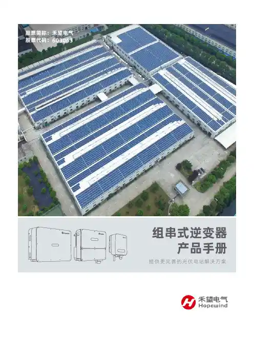
股票简称:禾望电气股票代码:603063公司简介深圳市禾望电气股份有限公司(股票代码603063)专注于新能源和电气传动产品的研发、生产、销售和服务,主要产品包括风力发电产品、光伏发电产品和工业传动产品等,拥有完整的大功率电力电子装置及监控系统的自主开发及测试平台。
公司通过技术和服务上的创新,不断为客户创造价值,现已成为国内新能源领域最具竞争力的电气企业之一。
在光伏并网发电领域,禾望电气提供具有竞争力的整体解决方案,包括集中/集散式大功率光伏发电系统和中小功率组串式光伏发电系统。
在集中式方案中,包括1100V系统用的500kW、630kW、800kW并网逆变器和1500V系统用的1250kW、1562.5kW、2500kW和3125kW并网逆变器,以及对应的1100V和1500V系统的直流汇流箱产品。
同时提供1MW、1.25MW、1.5625MW、2MW、2.5MW、3.125MW、4MW、5MW和6.25MW的逆变箱房式、箱变一体机式的一体化解决方案组合产品。
在集散式方案中,包括1100V系统用的1000kW和1250kW并网逆变器,同时提供1MW、1.25MW、2MW、2.5MW、4MW和5MW的逆变箱房式、箱变一体机式的一体化解决方案组合产品。
在组串式方案中,包括户用5kW~8kW单相机型,商用10kW~110kW的三相中功率机型、大型电站用40kW~125kW以及DC1500V 225kW大功率机型。
同时提供对应的WiFi/GPRS无线模块、智能数据采集器产品,满足系统的远程监控和运维管理需求。
总部及研发基地:深圳制造基地:深圳、苏州、东莞、盐城营销服务中心:北京、上海、俄罗斯服务基地:华南、华东、西南、西北、华北、东北片区等16个服务基地和遍布全国的服务点“”目录040608101214181500V大功率(225K)电站型应用(50K/70K/80K/125K)商用大功率(36K/40K/50K/60K/70K/100K/110K)商用中功率(10K/12K/15K/17K/20K/22K/25K/30K/33K)户用小功率(5K/6K/8K)通讯解决方案应用案例04050607080910111213141516171819山东省高密市组串式项目江苏泰州1.8MW项目菏泽市无量光伏20MW太阳能项目河北行唐县11.6MW扶贫项目2021广东惠州500kW项目四川攀枝花屋顶光伏发电项目江西瑞昌光伏发电项目山西汾矿50kW组串式逆变器项目2223山东省日照市莒县陵阳街道电站乌克兰4MW光伏项目安徽滁州定远光伏屋顶项目潍坊安丘市5MW项目山东省临沂市临沭县项目山东威海2.8MW光伏项目办公地址:深圳市南山区西丽官龙第二工业区11栋邮 编:518055客服热线:400-8828-705电 话:+86-755-86026786(总部)+86-10-82193180(北办)网 址:2020禾望电气股份有限公司版权所有。
EKSI ups说明书
EKSI ups说明书
爱克赛UPS电源是一款具有强壮适应性、装备灵敏的产品、选用先进的DSP数字操控技能,有用提升了产品功能和体系可靠性,并完成更高功率密度的集成和小型化,一起为了全方位满足用户的个性化需求,提供了十分丰富的可扩展功用,用户能够根据需要灵敏装备。
主要技能特征:
1、爱克赛ups10kva额外输入电压:660V-400V-380V-220V/50Hz 三相。
2、额外输出电压:400V-380V-220V-110V/50Hz三相。
3、功率容量:1.0KVA-200KVA。
4、抗电强度:铁芯-绕组3500VAC/50Hz/5mA/10s无飞弧击穿(工厂测试)。
5、绝缘电阻:1000VDC绝缘阻值≥100MV。
6、爱克赛upsek910h(s)10kva变压器噪声:小于65dB(变压器水平间隔点1米测试)。
7、防护等级:IP00或IP20。
8、绝缘等级:B,F级以上。
9、非标品可根据客户要求定做。
整机体系可靠性高:
选用微处理器操控/直接产生高频脉宽调制波(SPWM)对UPS逆变器进行操控,简化了UPS的操控电路,进步了UPS的安稳性。
数字化操控技能,确保UPS的一致性和可靠性。
网站免费下载WinPower2000监控软件。
为了使用户对UPS的办理愈加便捷、有用下载WinPower2000网络版监控软件,完成智能化办理。
装备IntelligentSlot智能插槽。
BND220- 1050A型 逆变器说明书讲解

电力专用逆变电源使用说明书前言衷心感谢您选用我公司产品,我公司生产的逆变电源主要针对电力系统的特点和要求设计制造,适合电力系统对供电设备高质量、高可靠性的要求,广泛应用于电力系统通信、载波、监控、继电保护以及事故照明等方面。
正确安装和使用本产品能更好发挥其作用,因此在安装和使用前应认真阅读用户手册。
本手册中对产品的技术原理,型号规格,安装说明,安全操作以及注意事项都有详尽的介绍,相信这将使您获得最充分的使用向导及服务保证。
再次感谢您的大力支持,我们将一如既往地坚持“质量第一,信誉至上,服务为本,平等互利”的原则与您真诚合作,共同发展。
相信我们的专业会给您带来放心的服务。
目录一、简介 ...................................................................................... 3二、系统工作原理 ...................................................................... 4三、外形结构与功能说明 .......................................................... 5四、产品安置注意事项 .............................................................. 8五、安装调试说明 ...................................................................... 9六、电源技术指标 .................................................................. 12七、服务保证 .......................................................................... 13八、附录(通信协议) .......................................................... 14一、简介1.1 概述BND 系列的正弦波逆变电源是电力和通信系统新一代专用电源,主要针对中国电网环境而设计,采用先进的正弦波脉宽调制(SPWM )技术,主电路采用德国西门子IGBT 模块,驱动保护为日本三菱厚膜电路,具有可靠性高、保护功能全、波形失真小、功率大等优点。
上能光伏逆变器产品手册说明书
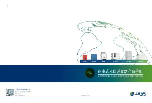
卓越 上能20200710组串式光伏逆变器产品手册整合世界500强光伏业务 全球领先的光伏逆变解决方案提供商地址:江苏省无锡市惠山区和惠路6号邮编:214174上能电气股份有限公司3~6kW 8~12kW 20kW 36~50kW 50~70kW 100~225kW上能电气股份有限公司(股票代码:300827)是一家专注于电力电子产品研发、制造与销售的国家高新技术企业。
公司深耕电力电子电能变换和控制领域,为用户提供光伏并网逆变、储能双向变流、电能质量治理等解决方案和系统集成,打造高效、安全、经济、绿色的电力能源。
上能电气始终坚持“以市场为导向、以创新促发展”的理念,全面推进产学研体系建设,先后建立了院士工作站、博士后科研工作站、博士后创新实践基地、CNAS实验室、省企业技术中心、省工程技术研究中心、省能源光伏逆变系统工程中心。
同时,上能电气以中国无锡为中心,建立现代工业产业园,并于2017年入选国家工信部首批绿色工厂,同年在印度班加罗尔建立光伏逆变器生产基地,以满足印度及周边海外市场不断增长的客户需求。
上能电气秉承“致力于成为世界级电源企业”的愿景,为业内打造完整的光伏逆变解决方案,提供3kW~6800kW全功率段集中式、组串式、集散式光伏逆变器,产品广泛应用于大型地面、山地、水面、工商业屋顶和户用等多种场景,满足客户多样化需求,连续四年为领跑者基地逆变解决方案核心供应商。
同时,上能电气拥有全功率段的交直流储能变流器产品,具备发电侧、电网侧、用户侧储能系统解决方案,助力能源互联和智能电网的快速发展。
在电能质量领域,上能电气拥有全系列有源滤波器、低压无功补偿器、三相不平衡治理装置等产品及解决方案,广泛应用于通讯、医疗、轨道交通、石油石化、冶金、烟草等各个行业,致力于为客户提供稳定高效的清洁电源。
目前,上能电气积极与国际知名集团开展紧密合作,业务遍及东南亚、中东、南美、欧洲、北非等市场,推动绿色能源在全球范围的广泛应用。
AIMS Power 10,000瓦直流到交流电源逆变器 (V 2.0) 使用说明书
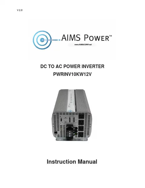
DC TO AC POWER INVERTER PWRINV10KW12VInstruction ManualIntroductionThe AIMS Power 10,000 watt inverter is the most technology advanced mobile DC to AC power inverter available. AIMS also offers the 8,000 Watt 12V or 12,000 Watt 24V.This inverter is used in a wide range of applications including back up power for remotehomes, off-grid systems, RVs, boats, commercial vehicles and mobile businesses. The10,000 watt inverter will operate most pumps, motors, lights, heaters, compressorbased appliances and hand tools.To get the most out of the power inverter, it must be installed and used properly. Readthe instructions in this manual before installing and using this product. Follow all safetyprecautions.FUNCTIONSFRONT VIEWA. On/Off switch: Leave in the OFF position during installation.B. Over temperature indicator: Lights when inverter protects itself against overheating. Invertershuts down while indicator is on. Inverter will restart automatically and indicator will turn off when the inverter cools.C. Over load indicator: Lights when inverter shuts down because of overload. Indicator will turn offand inverter will restart when overload is removed.D. Bar meters: Displays battery voltage and current. Current should be in the green zone forcontinuous operation. The inverter will operate for several minutes when the current is in the yellow zone. Operation with battery voltage or current in the red zone of a meter will result in protective shutdown of inverter.E. AC outlets: Maximum recommended output per outlet is 1500W.F. Remote port: Used with remote switch to turn inverter ON/OFF (sold separately).G. AC terminal block: Hard wire block providing inverter's full power.E: AC outletsD: Bar metersB: Over temperature indicatorA: On/Off switch C: Over load indicatorG: AC terminal Block F: Remote portREAR VIEWA: Fan: Do not obstruct, allow at least 12 inches for air flow.B: Battery terminals: Connect to 12V, or 24V, or 36V, or 48V (depending on inverter model) battery(s) or other DC power source. "+" is positive & " - " is negative. Reverse polarity connection will blow internal fuse and may damage inverter permanently. Make sure you check your input voltage and do not REVERSE POLARITY! This will void the warranty.C: Chassis ground lug: Connect to earth ground or to vehicle chassis using #8 AWG wire. Warning! Operation of the inverter without a proper ground connection may result in an electrical safety hazard.QUICK HOOK-UP AND TESTINGIf you would like to quickly hook-up the power inverter and check its performance before moving forward with your installation, please follow these guidelines:1. Unpack and inspect the power inverter, check to see that the power switch is in the OFF position.2. Before you connect the battery cables, make sure the power switch is in the off position. Connect Red (+) battery cable to Red (+) inverter terminal. Connect Black (-) battery cable to Black (-) inverter terminal. Connect Red (+) battery cable to Red (+) battery terminal. Connect Black (-) battery cable to Black (-) battery terminal. Alligator clamp cables may be used but only to connect to the battery. Do not use clamps on inverter terminals. Alligator clamps are not a permanent solution. You may see a spark during connection. Do not reverse the polarity. This may damage the inverter and void warranty. Caution! Loosely tightened connectors result in excessive voltage drop and may cause overheated wires and melted insulation. Reverse polarity connection will blow a fuse in inverter and may permanently damage the inverter. Damage caused by reverse polarity connection is not covered by our warranty. Warning! You may observe a spark when you make this connection since current may flow to charge capacitors in the power inverter. Do not make this connection in the presence of flammable fumes, as explosion or fire may result.A: FanB: Battery terminal (+)B: Battery terminal (-)C: Chassis grounding3. Set the power switch to the on position. Check the meters and indicators on the front panelof the inverter. The voltage bar graph should indicate 11 to 14 volts depending on the voltageof the power source. If it does not, check your power source and the connections to inverter.The other indicators should be off.4. Set power inverter switch to the OFF position, the indicator l ights may blink and theinternal alarm may sound momentarily. This is normal. Plug the test load into the ACreceptacle on the front panel of the inverter. Leave the test load switch off.5. Set power inverter switch to the ON position and turn the test load on, the inverter shouldsupply power to the load. If you plan to measure the true output R.M.S. voltage of inverter, ameter such as FLUKE 87A, BACKMAN 4410 or TRIPLETT 4200 must be used.INSTALLATION1. Where to installThe power inverter should be installed in a location that meets the following requirements:a. Dry - Do not allow water to drip or splash onto the inverter.b. Cool - Ambient air temperature should be between 0°C and 40°C, the cooler the better when operating in this rangec. Ventilation - Allow at least one inch of clearance around the inverter for air flow. Ensure the ventilation openings on the rear and bottom of the unit are not obstructed.d. Safety - Do not install the inverter in the same compartment as batteries or in any compartment capable of storing flammable liquids such as gasoline.2. CablesDC to AC inverters require high amperage/low voltage DC power to low amperage/high voltage AC power. To operate properly, connect inverter DC input terminals direct to battery with heaviest wire available see below:12 Volt Model: 2x set of 4/0 AWG (2 red + 2 black) and quantity 2- ANL500KIT-500 Amp fuse kits for positive (red) cablesBattery Cables InstallationWhen connecting the AC inverter to the battery terminals, it is important to connect the "+" wire to the "+" terminal and the wire to the "-" wire to the “-“ terminal. Do NOT reverse the polarity. It will void the warranty. Make sure you connect negative to negative and positive to positive.Red (+) * 2Black (-) * 2REDBLACKCaution!DO NOT allow the wires to cross or touch each other. Install the cables facing away from each other and screw tightly. When connecting the battery cables to the terminals of the inverter, make sure they do not touch the case.3. GroundingThe power inverter has a lug on the rear panel marked "chassis ground" This is to connect the chassis of the power inverter to the ground.The ground terminals in the AC outlets on the front panel of the inverter are also connected to the ground lug.The chassis ground lug must be connected to a grounding point, which will vary depending on where the power inverter is installed. In a vehicle, connect the chassis ground to the chassis of the vehicle. In a boat, connect to the boat's grounding systems in a fixed location, connect the chassis ground lug to an earth point, which will vary depending on where the power inverter is installed.The neutral (common)conductor of the power inverter AC output circuit is connected to the chassis ground. Therefore, when the chassis is connected to ground, the neutral conductor will also be grounded.This conforms to national electrical code requirements that separately derived AC sources (such as inverters and generators) have their neutral tied to ground in the same way that the neutral conductor from the utility line is tied to ground at the AC breaker panel.Caution! The Negative DC input of the power inverter is connected to the chassis. DO not install the power inverter in a positive ground DC system. A positive ground DC system has the positive terminal of the battery connected to the chassis of the vehicle or to the grounding point.Warning! Do not operate the power inverter without connecting it to ground. Electrical shock hazard may result.OPERATIONTo operate the power inverter, turn it on using the ON/OFF switch on the front panel. The power inverter is now ready to deliver AC power to your loads. If you are operating several loads from the power inverter, turn on separately after the inverter has been turned on. This will ensure that the power inverter does not deliver starting currents to all of the loads at once.1. Controls and indicatorsThe ON/OFF switch turns the control circuit in the power inverter on and off. It does not disconnect power from the power inverter.When the switch is in the OFF position, the power inverter draws no current from battery. When the switch is in the ON position but with no load, the power inverter draws less than 450 mA.2. Battery voltage indicatorThe battery voltage bar graph indicates the voltage at the input terminals of the power inverter. At low input current, this voltage is very close to the battery voltage. At high input current, this voltage will be lower than the battery voltage because of the voltage drop across the cable and connections.Ideally, the voltage should remain in the green area of the bar graph. If the voltage goes into the red area at top or bottom of the graph, inverter may shut-down.3. Battery current indicatorThe battery current bar graph indicates the current drawn from the battery by the power inverter, it will not indicate current by other loads also connected to the battery. The indicator only displays DC volts and amps.For long term operation, the current should be in the green area of the bar graph. Short term operation is possible with current in the orange area. If the current rises to the red area, the inverter will reduce its output voltage to protect itself.To measure AC current, use a TRUE RMS MULTI METER.4. Over temp indicatorThe over temp indicator indicates that the power inverter has shut itself down because it has become overheated. The power inverter may overheat because it has been operated at power levels above its rating, or because it has been installed in a location which does not allow it to dissipate heat properly.5. Over load indicatorThe over load indicator indicates that the power inverter has shut itself down because its output circuit has been short circuited or drastically overloaded. Switch the ON/OFF to OFF, correct the fault condition, and then switch the ON/OFF back to ON.THINGS TO CONSIDER REGARDING THE LOADThe 10,000W inverter will operate most AC loads within its power rating. When determining whether a microwave oven can be operated by the 10,000W inverter, remember that the power commonly advertised for microwave ovens is the cooking power (the power delivered to the food) not the power actually consumed by the microwave oven. The microwave oven will consume 40% to 100% more than its advertised cooking power. Check the rating sticker on the back of the oven to determine its actual power draw. The 10,000W inverter will operate small microwave ovens (0.2 to 0.3 cubic foot capacity) that draw is about 1700 watts.Some induction motors used in refrigerators, freezers, pumps, and other motor operated equipment require very high surge currents to start. The power inverter may not be able to start some of these appliances even though their rated current draw is within the rating of the power inverter.If a motor refuses to start, observe the battery voltage indicator while trying to start the motor. If the battery voltage indicator drops below 10.5V DC while inverter is attempting to start the motor, this may be why the motor won't start.Make sure that the battery connections are good and that the battery is fully charged. If the connections are good and the battery to is charged, but the voltage still drops below 11 volts, you may need a larger battery or larger battery bank.(*2 for 24V *3 for 36V *4 for 48V)INPUT VOLTAGEThe power inverter will operate from input voltage ranging from 10V-16V. If the voltage drops below input range, an audible low battery warning will sound and the voltage indicator will be in the lower red zone. The power inverter will shut down if the input voltage drops below 10V +/- .5V. This protects your battery from being over discharged.The power inverter will also shut down if the input voltage exceeds 17V +\-.5V. This protects the inverter against excessive input voltage.The voltage indicator will be in the upper red zone. Although the power inverter incorporates protection against over voltage, the inverter is at risk of permanent damage if the input voltage is allowed to exceed 17V +\-.5V.TROUBLESHOOTINGmon problemsa. Buzz in audio systems:Some inexpensive stereo systems and radios will emit a buzzing noise from their loudspeakers when operated from the power inverter. This is because the power supply in the device does not adequately filter the modified sine wave produced by the power inverter. The only solution is to use a sound system that incorporates a higher quality power supply.b. Television interference:Operation of the power inverter can interfere with television reception on some channels. If this situation occurs, the following steps may help to alleviate the problem.-Make sure that the chassis ground lug on the back of the power inverter is solidly connected to the ground system of your vehicle, boat or home.-Do not operate high power loads with the power inverter while watching television.-Move the television as far away from the power inverter as possible.-Keep the cables between the battery and the power inverter as short as possible and twist them together with about 2 to 3 twists per foot. This minimizes radiated interference from the cables.SPECIFICATIONSAIMS Corp., Inc. dba AIMS Power Warranty Instructions:This product is designed using the most modern digital technology and under very strict quality control and testing guidelines. If, however you feel this product is not performing as it should, please contact us:**************************(775)359-6703We will do our best to resolve your concerns. If the product needs repair or replacement, make sure to keep your receipt/invoice, as that will need to be sent back along with the package and RMA# prepaid to AIMS. You have a full 1 year warranty from date of purchase.This warranty is valid worldwide with the exception that freight and duty charges incurred outside the contiguous 48 United States will be prepaid by customer.Except as provided above, AIMS Power makes no warranty of any kind, express or implied, including without limitation the implied warranties of merchantability and fitness for a particular purpose. In no event shall AIMS be liable for indirect, special or consequential damages. This warranty only applies to AIMS Power branded products. All other name brand products are warranted by and according to their respective manufacturer. Please do not attempt to return non-AIMS Power branded products to AIMS Power.For additional products such as:-Modified sine wave inverters-Pure sine wave inverters-Low Frequency Inverters-Solar Charge Controllers-Micro Grid Tied Inverters-Inverter Chargers and Automatic transfer switches-Converters DC-DC-Custom cut cables-Batteries-Solar Panels & RacksPlease visit our web site: Tofindoutwheretobuyanyofourproducts,youmayalsoe-mail:************************ (775)359-6703.。
FR-UK系列INV逆变电源中文使用手册
性 音频噪声 (dB) 保护功能 防雷功能(选件) 工作温度 相对湿度 尺寸 (mm) (长×宽×高) 重量 (Kg)
● 指标变动恕不另行通知。
FR-UK/B 使用手册
二二、、技技 术术 指指 标标
FR-UK/B3110 FR-UK/B3120 FR-UK/B3130
380±25%
50±5%
三相五线
FR-UK/B 使用手册
一一、、概概 述述
FR-UK/B3110、B3120、FR-UK/B3130 系列并联型 INV 是主要为网络计算机房和小型智能设备 (如测量装置、工业自动化设备等)设计的高性能在线式正弦波不间断电源,该产品采用拥有自主知识 产权的并联技术,可以任意并联扩容或 N+1 冗余并联,提高电源系统的可靠性,为中国的大功率 INV 用户提供了一种理想的、可并联的 INV 产品。
灯亮表示 INV 电源故障。 (8)、 并 机 线 指 示 灯
灯亮表示 INV 电源的并机线连接故障。 (9)、 保 险 丝 指 示 灯
灯亮表示 INV 电源的直流保险丝断路。
第5页
FR-UK/B 使用手册
(10)、 整 流 器 指 示 灯 灯亮表示 INV 电源的整流器故障。
(11)、“ 左 ” 键 (12)、“ 上 ” 键 (13)、“ 确 认 ” 键 (14)、“ 下 ” 键
(12) (11)
(13)
(14)
图8 1.1 图示说明
(1)、大屏幕点阵式中文 LCD 液晶显示屏 通过“上”、“下”两个键可翻动显示屏,按顺序可浏览“流程图屏”、“交流输入参数屏”、“直流输
入参数屏”、“交流输出参数屏”、“INV 工作状态屏”、“帮助信息屏”等。 (2)、 开 机 键
逆变器参数
额定交流频率/范围[Hz]
50
50
50
50
功率因数(cosφ),可调
0.9超前…0.9滞后
0.9超前…0.9滞后
0.9超前…0.9滞后
0.9超前…0.9滞后
额定功率下总谐波畸变率(THDi)
<3%
<3%
<3%
<3%
效率
最大效率
98.0%
98.0%
98.2%
98.1%
-20~+60
(高于45°C开始减载)
-20~+60
(高于45°C开始减载)
-20~+60
(高于45°C开始减载)
-20~+60
(高于45°C开始减载)
防护等级
IP65
IP65
IP65
IP65
隔离类型
无变压器隔离
无变压器隔离
无变压器隔离
无变压器隔离
夜间损耗[W]
<5
<5
<5
<5
散热方式
强制风冷
强制风冷
符合人体工程学的结构设计和人性化的操作界面,便于安装维护
产品型号及技术参数:
逆变器型号
SolarLake 10000TL
SolarLake 12000TL
SolarLake 15000TL
SolarLake 17000TL
直流输入参数
最大输入功率(STC组件) [W]
11500
13800
17300
19600
欧洲效率
97.6%
97.6%
97.7%
97.6%
PDB220-22 双向电源模块说明书
有
故障清除后自恢复
故障清除后 5s 后自恢复
-20℃ ~+45℃满足模块完全性能工作;45℃ ~+70℃降额
温度:-20℃ ~+85℃;湿度:10~95%RH,无冷凝
CAN 通讯,支持在线升级
支持
蓝灯:正常;红灯:异常
螺钉规格:M4;最大扭矩:1.5N.m
螺钉规格:M6;最大扭矩:3.0N.m
3.96MM 端子
说明:以上未特别注明的测试条件的指标,均默认为: 230Vac&25℃;②低压侧电压,也可根据客户需求调整至:14Vdc~16Vdc
△! 温馨提示:低压直流侧电压应小于 25Vdc,避免过压致使直流侧输出固态电容爆裂。
2/2
版权所有@深圳市普德新星电源技术有限公司,本手册内容如有更改恕不另行通知 !
效率
整流效率 逆变效率
电压范围
交流参数
(整流输入& 逆变输出)
电压频率 最大电流 电流谐波(THDi)
功率因素
整流输出电压
电压
逆变输入电压 稳压精度
工频纹波
电流
整流输出电流 逆变输入电流
开机时间
开机过冲
启动冲击电流
正反向切换速度
直流短路保护
直流过功率保护
直流过压保护
交流过欠压/过欠频及孤岛保护
过温保护
同时,解决了风扇噪声大的痛点,属于行业同系列最低噪的产品。
产品特点
整流‐逆变能量双向流动 正反方向高效率 正反方向无缝切换 超强过载能力 产品轻量化,超低噪音 完善的故障保护功能 支持 BootLoader 在线升级,具备以太网 升级和智能在线故障分析功能 良好的电磁兼容性,满足 EN55032 ClassA 标准 可通过 UL/TUV/CE/CCC 认证
古瑞瓦特逆变器说明书
GW17K-DT 22100 17500
22/22 4 2(可并联)
17000 17000
25
98.2%
GW20K-DT 26000 20500
22/22 4
20000 20000
30
98.4% >98.1%
0.9 超前~0.9 滞后 3W/N/PE
98.0% >97.7%
99.9% 集成 集成 集成(可选) 集成 集成 NB-T 32004 NB-T 32004 NB-T 32004 516*650*203mm 39 壁挂式 -25~60°C (>45°C 减载) 0~95% 3000m IP65 无变压器 <1 强制风冷 <45 3 LED; 5'' LCD USB2.0; RS485 或WiFi 5/10/15/20/25( 可选)
直流输入
交流输出 效率ห้องสมุดไป่ตู้保护
证书和标准
常规参数
最大推荐接入组串功率(W) 额定直流功率(W) 最大直流电压 (V) MPPT电压范围 (V) 启动电压 (V) 最大直流电流(A) 输入路数 MPPT路数 直流端子类型 额定交流功率(W) 最大交流功率(W) 最大交流电流(A) 额定输出 输出范围 电流总谐波失真 功率因素 电网类型 最大效率 欧洲效率 MPPT效率 残余电流保护 孤岛保护 直流开关 输出过流保护 绝缘阻抗侦测 并网标准 安规 电磁兼容
3W/N/PE 98.2%
>97.7% 99.9% 集成 集成
集成(可选) 集成 集成
NB-T 32004 NB-T 32004 NB-T 32004 516*650*203mm
39 壁挂式 -25~60°C (>45°C 减载) 0~95% 3000m IP65 无变压器
荷兰 VTN 逆变电源、充电器 说明书
荷兰VTN 能源公司具有25年的高质量移动电源的研发和制造经验,产品主要用于:! 内陆船舶、游艇! 野营帐篷、旅行车队, 大篷车 ! 特殊交通工具:救户车、消防车、移动银行! 火车!应急电源!其他无220V 交流电源供应或经常断电的场所[高可靠性的全线产品]VTN 公司有长期积累的移动电源产品生产经验,系列产品包括:# PH 系列逆变器# PH-M 系列逆变器(带充电器)# 蓄电池充电器 # 蓄电池监测仪# 附件:远程监控面板、转换开关#WhisperGen 直流发电机[移动电源供应的设备]VTN 逆变电源可带的设备包括:电脑、电视机、音响设备、微波炉、冰箱、咖啡炉、雷达通讯导航设备、照明灯具、电动机等家用和其他电器设备。
[质量政策]VTN 获得ISO9001证书,CE 认证。
PHOENIX INVERTER (PH 逆变器逆变器))系列[ 12V :220W-2500W ] [ 24V :220W-3000W ] [ 48V :220W-3000W ]4电脑、冰箱等负载 3PH 逆变器 性能特点! 效率高、稳定的正弦波输出,高频技术,体积小、重量轻,适合各类负载适合各类负载。
! 启动功率大启动功率大:特别适合如冰箱、压缩机、电动工具等负载,传统高频技术不能提供类似性能。
24V/800型号可启动一冰箱。
! 并机和三相连接性能提供无限制的功率输出并机和三相连接性能提供无限制的功率输出:多达6台PH 24/3000系列并机提供18KW 的功率输出,并且可连接成三相达54KW 的输出。
! 切换负载到另一AC 回路(自动切换开关):对于1200V A 以上的型号,推荐使用PH-M 系列,该系列已内置转换开关,低功率型号推荐使用FILAX 切换开关,由于转换时间很短(小于20MS ),电脑和其他电子设备工作不受影响。
! 电脑接口电脑接口::配有RS485接口接口,,可通过电脑设置逆变器参数可通过电脑设置逆变器参数,包括输出电压、频率、编程继电器开关,此继电器开关可用来表示报警信号、或启动发电机,逆变器可通过VENet 来实施监控。