台湾泰仕TES1306产品参数
浙江天正电气股份有限公司万能式断路器说明书
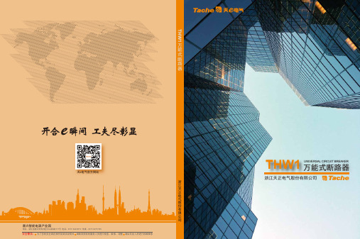
UNIVERSAL CIRCUIT BREAKER浙江天正电气股份有限公司浙江天正电气股份有限公司天e电气官方网站万能式断路器嘉兴智能电器产业园为了您的安全请在操作前阅读说明书 请联系授权的服务人员进行检查、维修、调整 请由专业人员进行拆解维修安全警告:THW1THW1万能式断路器005THW1系列断路器结构图断路器选型表产品参数表智能控制器介绍智能控制器功能区别及增选智能控制器保护特性产品附件介绍产品二次回路接线图双电源控制器接线图产品外形及安装尺寸图产品运行条件产品订货须知THW1万能式断路器目录005006007009013015021032038040051053Catalogue1抽屉座2本体3面罩4智能控制器5电动操作机构6辅助7欠压脱扣器分励脱扣器闭合电磁铁8二次接线端子45768123THW1系列THW1系列断路器选型表序号12345678910111213141516TH壳架断路器11600 2000 3200 4000 6300常规:无 H:高分断3P 4P200A …… 6300A固定 抽屉水平 垂直 上水平下垂直 下水平上垂直缺省:M型 除缺省外,其他型号控制器需注明:3M型 3H型 3P+N(T型)3P+N(W型)AC220V/230V AC380V/400V DC220V DC110V如有多种电压等级特殊说明中说明缺省:无 选配:欠压瞬时欠压延时1s/3s/5s/7s缺省:无 AC220V/230V AC380V/400V当欠压电压与控制回路电压不一致时,需要注明缺省:四开四闭选配(需注明):五开五闭 六开六闭缺省:无高原 湿热 环保 盐雾 低温缺省:无 杠杆联锁 缆绳联锁 一锁一钥匙两锁一钥匙 三锁一钥匙 加长母排 电气三位置指示门连锁 双电源控制器 按钮锁 ……企业代号产品大类设计序号壳架电流分断能力极数额定电流安装方式接线方式控制器代号控制回路电压欠压脱扣器类型辅助触头代号欠压脱扣器电压应用场合特殊要求序号说明TH W120002000A AC220V/230V AC220V/230V3P1S3M型杠杆联锁抽屉五开五闭水平高原H42153612897111013141516产品参数表THW1系列万能式断路器(以下简称断路器),适用于交流50Hz,额定电压AC380V~AC690V,额定电流200A~6300A的配电网络中,用来分配电能和保护线路及电源设备免受过载、短路、欠电压、单相接地或剩余电流等故障的危害。
ATIser泰矽温控器说明书

ATIser泰矽温控器说明书
ATIser泰矽温控器
规格:
TA48---W=48*H=48
TA72---W=72*H=72
TA96---W=96*H=96
TA96W---W=96*H=48
TA96H---W=48*H=96
功能特点:
内置9种温度检测讯号及模拟讯号输入设定
3组PID自整定功能,输出%限制参数
检测值(温度斜率校正)(温度补偿)功能
负载加热丝断线警报:自动检测负载电流,当负载电流小于断线警报设定值,断线警报动作(选购功能)
温度、湿度、流量、压力、PH、mA、mV等多种输入模式选择变更:多种输入模式,只需软体变更设定,不需更换机型硬体;提供多种输出模式方案选择
遥控输出、传送输入:主表传送当前PV值或SV值参数资料给副表
加热冷却变输出控制,恒温精确
RS485通讯功能,与各种控制元件之间通讯,交换参数资料
自动演算偏移值执行:执行自动演算过程中PV值不超温下完成
温度斜率校正:调整因外界或元件造成温度检测值偏差
3组PID输出设定、控温精确:自动填入(SV设定值范围内)最佳PID值,达到大范围温度精确控制
面板控制指示灯:随机显示工作状态,监控一目了然
内建回归出厂值功能
丰富异常显示讯息显示:故障发生立即显示异常原因,故障容易排除
输出上下限设定:输出百分比设定(0-20mA DC0-10V)
高精度AT自动演算:自动演算功能,达到最佳控温效果
手动演出功能:手动百分比输出设定,试机更安全
内部采用分离式设计:分别为电源板/控制板/显示板;各板之间采用卡槽连接,维修更换容易。
AI-Tek Instruments Tachometer产品介绍说明书

About AI-Tek ® TachometersNot all tachometers are the same, and this is certainly true of the AI-Tek Instruments tachometry line.Designed with severe industrial environments in mind, these units will provide reliable around-the-clock operation for years under adverse conditions.AI-Tek Instruments is a leader in manufacturing this type of instrument.Our prices reflect the design, quality, ruggedness and engineering of the equipment. What your eally get with AI-Tek Instruments is a superb price performance ratio. It may not initially be the least expensive equipment available; but, in the long run, the value of this equipment is that it will outperform and outlast others.Introduction of the New Generation Tachometer LineThe new generation TACHPAK and TACHTROL series tachometers have been designed with all of the functions and durability embodied in the previous tachometer series as well as improvements to e xtend performance, accuracy and function. With the exception of the Tachtrol 20, both TACHPAK and TACHTROL now share a c ommon processing platform. This commonality allows both to perform identical tachometry f unctions, streamlines programming and minimizes thel earning curve. The main physical difference between the two is the characteristic integrated display function found in all TACHTROL series tachometers.Common Specifications:Temperature -10°C to +55°C operating; -40°C to +80°C storageThermal Cycle 50 cycles: -40°C to +80°C; 200 cycles: -10°C to +55°C Humidity 90% RH non-condensing per IEC 654-1, IEC 68-2-3VibrationMIL-STD-810C Environmental Test Methods, method 514.2, procedure VIII, figure 514.2-6, curve V; 1.5g’s 10-2000 Hz, 5.5 hrs./axis, 3 axis IEC 60068-2-6, 10-150Hz, 2g, 10 sweep cycles / axis, 3 axisShockMIL-STD-810C Environmental T est Methods, method 516.2, procedure I and figures 516.2-2, for ground equipment; 30g’s half sine, 11ms. 3 axis, 18 total IEC 60068-2-27; 50g half sine, 11ms, 3 axis, 18 totalEMCCE CompliantEN 61326:1997 Class A radiated and conducted emissions with amendments A1-A3EN 61326:1997 with amendments A1-A3, ImmunityEN 61000-4-2: 1998 Electrostatic Discharge: ±4kV contact, ±8kV air EN 61000-4-3: 1998 Radiated Immunity: 10V/mEN 61000-4-4: 1995 Electrical Fast Transients/Burst: ±2kV AC, ±1kV I/O > 3mEN 61000-4-5: 1995 Surges: ±1kV differential mode, ±2kV common mode, ±1kV lineto ground I/O > 30mEN 61000-4-6: 1996 Conducted Immunity: 3VEN 61000-4-11: 1994 Supply Dips and VAriations: 100%, 0.5 cycles each polarity RoHS RoHS compliant per European Directive 2002/95/ECSupport Documents On Website Include:TACHLINK , Manual, Tach Training VideoTach TACHPAK 10 & 30and TACHTROL 10 & 30are shipped in a single cartonPackage containing one instrument, TACHLINK , a manual on CD ROM, and a USB cable.Contents:TACHTROL plus is shipped in a single carton containing one instrument and ad isplay cable with RJ-11 terminations. TACHTROL 10 & 30and TACHTROL plus Explosion Proof and NEMA 4X are shipped in a single carton containing onei nstrument and accessories as described above, one infrared remote and one DIN rail mounting kit. TACHPAK 10 & 30 Explosion Proof and NEMA 4X are shipped in a single carton containing one rated enclosure and one i nstrument and accessories as described above.It is the customer’s responsibility to determine whether the product is proper for customer’s use and application.A I -T e k I n s t r u m e n t s ,C h e s h i r e ,C T U S ASpecifications (Continued): ElectricalAll measurements taken at 25°C unless otherwise specified.Input PowerPower consumption3.5 watts, typical for tachometer onlyAdd 0.5 watts per remote displayAdd 2.0 watts for 12V out9.5 watts max.DC Voltage12-30 volts. Reverse polarity protected. Available on terminal blocks and din rail in parallel (TACHPAK only). AC Voltage80-264 Vac 50-60 HzPower SharingIf DC input and AC input are both supplied, DC will be loaded above approximately 15 volts. Below 15Vdc input, AC will be loaded.Output PowerRegulated to 12 volts @ 150mA when input voltage is 13.6 volts and above. Below 13.6 volts, output voltage ≈ input voltage –1.5V.Input Signal CharacteristicsChannel A & BFrequencyUpper Limit: 50 kHz absolute maximum(20µsec period); 40kHz typicalLower Limit: 0.005 Hz absolute minimum(200 sec. period); .05 Hz typical Minimum Pulse Width: 0.5 µsec.Wave shape: Square or SinusoidalInput Impedance12 kΩ typicalInput SensitivityUpper and Lower Limit: +/-30 volts max. (AC or DC). Logic 0 and Logic 1 thresholds are user adjustable from 200mV to +28 volts in approx. 20mV steps +/-3%. 200mV peak absolute min. imput sensitivity. Common Mode Rejection Ratio>40 db @1kHz typicalElectrical IsolationChannel A, B and Direction share common ground Channel A, B or Direction to output: 500 Vrms Channel A, B or Direction to ground: 500 Vrms Verify and ResetFrequencyEssentially DC, Minimum Pulse Width: 250 µsec.Input Impedance10mA current regulatedInput Sensitivity3.5 volts min. pulse to groundCommon Mode Rejection Ratio>40 db @ DC typicalElectrical IsolationSignal to signal 500 VrmsSignal to ground 500 VrmsDirectionFrequencyEssentially DCMinimum Pulse Width: 0.5 µsec.Input Impedance12 kΩ typicalInput SensitivityUpper and Lower Limit: +/-30 volts max. (AC or DC).Logic 0 and Logic 1 thresholds are user adjustablefrom 0 to 28 volts in approx. 20mV steps +/-3%.Common Mode Rejection Ratio>40 db @1kHz typicalElectrical IsolationChannel A, B and Direction share common groundDirection to output: 500 VrmsDirection to ground: 500 VrmsOutput CharacteristicsRelays (Mechanical)PhysicalForm CContact Rating10A @125/250 Vac, 6A @ 277 Vac, 5A @ 30Vdc,0.5A @ 100Vdc2500 VAResponse Time (operate and release)Input to output 16.5 msec max.(10 msec relay only)Electrical Isolation1500 Vrms, 1 minute coil to contactsSwitchpoint AccuracyInternal instrument accuracy to alarmsetpoint: ±.005%AI-TekInstruments,Cheshire,CTUSARelays (Solid State)Physical Form AContact Rating400mA @ 60V (AC or DC)On resistance: 2Ω maxResponse Time (operate and release)Operate: 2 ms max, 0.8 ms typical Release: 0.5 ms max, 0.1 ms typical Electrical Isolation 500 Vrms, 1 minuteSwitchpoint AccuracyInternal instrument accuracy to alarm setpoint: ±.005%Analog OutputRanges0 to 20mA, 4 to 20mA, -20 to 0 to +20mA;user selectableAccuracyInternal instrument accuracy: ±.005%; plus ±.05% of full scale range at room temp with 400 ohm load;±0.1% over temp range and load range. Unit is factory calibrated. Can be re-calibrated using TACHLINK.ResolutionStep size: 610 nanoamps per lsb. 16 bit D/A Linearity±0.02% typical Loop Impedance 100-1000 ΩResponse TimeInput to output 6.55 msec+ 1 msec settle at 1k Ω (worst case) to .1% of final valueElectrical Isolation 500 Vrms continuousDisplay (applies to TT & TTplus)ResolutionBlack and White graphics display. 64x128 Pixels.Accuracy±.05% of full scaleCommunication ProtocolRS485: 19.2kbaud, 8-n-1 protocol, Half duplex,Tachometer is bus masterNetwork• Multiplex up to seven displays plus one integrated display. Displays are addressable.• With all seven displays at the end of one RJ11 6-4cable, max length would be 125 ft (38m), limited by voltage drop in cable. Cable must be 1:1 type (not flipped), described as RJ11 6-4 reversed cable. For longer distances the RJ type cable should not be used. With #18 wire max run to a single display is 1000 ft (305m).• Response time: 1 second update to all displays, PC and RS485Electrical Isolation500Vrms to ground continuousUtility RS485Full access to TACHLINK, single drop only Communication ProtocolRS485: 19.2kbaud, 8-n-1 protocol, Half duplex,Tachometer is bus master Maximum Transmission Distance 8000 ft (2400m)Electrical Isolation500Vrms to ground continuous USBFull access to TACHLINK,Version 1.1 / 2.0 compatible Processing PlatformPIC18F series micro controller Clock Speed10MHz, ±50 ppm at room tempAcquisition TimeBasic instrument acquisition time / period 6.55 ms AccuracyBasic instrument accuracy ±.005% (50 ppm)ResolutionBasic instrument resolution: ±.025% or betterA I -T e k I n s t r u m e n t s ,C h e s h i r e ,C T U S ATACHLINK• TACHLINK is a Windows-based program developed to simplify programming, communicationand monitoring with the new generation of AI-TEK tachometers via USB2.0 or RS485.• Programming is much faster and simpler with TACHLINK.• T achometer configuration databases can be stored, backed up and retrieved easily. A storedd atabase can be used to program multiple tachometers and can be e-mailed to remote locations.• The TACHLINK graphical user interface allows any PC to be used as a remote display.• Analong output calibration is available only through TACHLINK and allows the customer to p erform and verify calibration status.• Plotting function is available only through TACHLINK and allows the customer to monitor a process over time while montioring speed and relay status. Output is available to be viewed real-time or can be captured and imported into a spreadsheet format for future analysis.A I -T e k I n s t r u m e n t s ,C h e s h i r e ,C T U S ATACHTROL 30 Key Features (T77630):• Wide range of AC or DC power (12-30 Vdc, 80-264Vac 50-60Hz)• Greatly improved instrument accuracy, processing speed and response time.• Frequency, period or counter modes.• User-defined inputs for logic level, averaging, alarm set points and hysteresis,• Signal normalization and math functions allow mathematical manipulation of input signals.R esults can be displayed along with user-defined units.• Accepts sinusoidal and square wave inputs as found in variable reluctance and digital output speed sensors.• Accepts bi-directional sensor inputs and will decode quadrature or direction signal logic • 2 solid state relays (fast response time) and 2 mechanical relays (high power)• Analog output: 0-20mA, 4-20mA, -20-0-(+) 20mA (can be used with bi-directional sensor)• Two programming methods: Front panel on display or USB2.0 connectivity to PC / Windows-based TACHLINK .• Utility RS485communication allows full TACHLINK function over longer distances (up to 8000 ft) • Drives up to 7 remote displays (TACHTROL plus ). A single display can be up to 1000 ft away with a simple RJ11(phone jack) connection. Longer runs, cable type and number of displays will affect distance.• Security mode protects unauthorized access for programming or alarm resets (through display or TACHLINK )• Environmentally hardened for temperature, vibration and shock. EMC / CE compliant to current BS / EN directives.• Has integrated display and will mount in same panel opening as TACHTROL 3• Display capabilities include two independent output channels for speed, count period or equation results, Alarm status / security, Mode, User defined units for each channel, 128x64 LCD graphics display with backlight.• Designed and manufactured compliant with RoHS.TACHTROL 10 Key Features (T77610):• Same as TACHTROL 30but excludes solid state relays, analog output and utility RS485It is the customer’s responsibility to determine whether the product is proper forcustomer’s use and application.TACHTROL ®10 & 30Dual InputDigital TachometerPart Number Series T77610 &T77630RoHSA I -T e k I n s t r u m e n t s ,C h e s h i r e ,C T U S AProgramming FeaturesProgramming has been greatly simplified and can be accomplished by 2 different methods. Many configurable attributes have been added to improve flexibility and function.• Display front panel: TACHTROL 10 and 30can be programmed through the integratedd isplay/membrane panel. Programming is accomplished by navigating through a series of nested menus. In the case of tachometer instruments embedded in explosion proof or NEMA 4X enclosures, remote access solves the problem of programming by making use of an IR link to allow full front panel control via a hand-held remote.• PC / Windows-based TACHLINK : Custom software allows the user to p rogram all configurable attributes of TACHTROL by PC via a USB2.0or RS485connection. In addition, the PC can be used to display data, perform security functions, d iagnostics, analog output calibration and real-time data logging; all available through the TACHLINK .Applications:• Fast response overspeed shutdown • 2 Channel Speed/Draw Monior • Bi-directional Tachometer • Reverse Rotation Alarm • Low Speed Tachometer • Clutch Slip Alarm • Winder Control• Ahead/Astern Marine Tachometer• Expanded analog Scale Speed Transmitter• Flow Rate Monitor • Process Time Monitor • Time per Event Monitor • Autoranging Tachometer • Computer Signal Conditioner • Averaging Tachometer• Line Frequency Monitor 60.00 Hz/400.0 Hz • RS485 Speed TransmitterOrdering Input Power Enclosure Net Weight P/N(lbs.)T77610-1080-264 Vac/12-30 Vdc Std. Panel Mount 0.8T77610-4080-264 Vac/12-30 Vdc NEMA 4X3.9T77610-7080-264 Vac/12-30 Vdc Explosion Proof 42.0T77630-1080-264 Vac/12-30 Vdc Std. Panel Mount 0.9T77630-4080-264 Vac/12-30 Vdc NEMA-4X4.0T77630-7080-264 Vac/12-30 VdcExplosion Proof42.0A I -T e k I n s t r u m e n t s ,C h e s h i r e ,C T U S APANEL MOUNT, STANDARD ENCLOSUREA I -T e k I n s t r u m e n t s ,C h e s h i r e ,C T U S AA I -T e k I n s t r u m e n t s ,C h e s h i r e ,C T U S ATACHTROL Enclosure Options T77610-40T77630-40NEMA 4XA I -T e k I n s t r u m e n t s ,C h e s h i r e ,C T U S ATACHTROL Enclosure OptionsT77610-70 / T77630-70EXPLOSION PROOFUL/CSA for Hazardous LocationsClass I, Groups B, C & D Class II, Groups E, F & GClass IIIAlso Class I, Zone 1, Groups IIB + H 2, IIAATEX 0102 EX II 2 GFor use in Zone 1 Groups IIA, IIB & IIB+H2 T6 or T5,IP66 hazardous locations Certifications Inside Enclosure (Consult Factory for Latest Update)A I -T e k I n s t r u m e n t s ,C h e s h i r e ,C T U S A。
教室音频系统安装及操作手册说明书
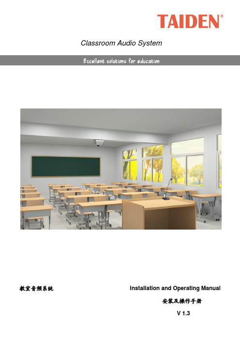
Classroom Audio System教室音频系统 Installation and Operating Manual安装及操作手册V 1.3重要的安全说明重要的安全说明1. 在安装和使用设备前请先仔细阅读本安全操作规程。
2. 请保存好您的安全操作指南便于以后作参考用。
3. 请遵守所有设备操作指南中的“警告”事项。
4. 须遵守各项操作指南中的规章原则。
5. 清洁设备:清洁设备之前,请先关掉电源,从插座中拔出设备插头,将各连接的系统单元拆卸出来,清洁时请用干燥的软布擦拭。
6. 未经生产厂家同意,不要使用任何不匹配的附件配置,这都有可能引起危险事故。
7. 勿将设备置于潮湿或靠近热源的地方,以免发生危险。
8. 设备不应遭受水滴或水溅,不应放置诸如花瓶一类装满液体的物品。
9. 电源插头作为断接装置,应便于操作。
10. 设备应可靠连接到带保护接地的电网电源输出插座上。
11. 勿将设备放置在不稳固的台面上;在运输过程中避免设备遭受强烈振动而引起损坏,建议在运输前选用合适的包装或使用原包装。
12. 请勿阻塞设备上的通风开口,并保持室内的空气通畅,便于设备的维护。
13. 供电电压:AC 100 V-240 V 50 Hz/ 60 Hz14. 设备连接所需要的延长电缆线请绕道穿行,勿有重物挤压,这样能有效维护系统的正常工作。
15. 每套系统中所连接的接收器不得超过规定数量,否则可能会导致整个系统中设备的异常工作,如有特殊要求请与距离您最近的深圳台电售后服务中心取得联系。
16. 确保设备不被任意拆开机壳,也不允许任何硬质导体或液态物质残留在机壳内。
17. 设备有需要维护时,不要自行拆卸,请及时与距离您最近的深圳台电售后服务中心取得联系。
18. 所有TAIDEN产品将提供一定期限(详见保修卡)免费保修,但人为损坏除外,例如:A. 设备因人为作用被摔坏;B. 因操作员操作不当而导致设备受损;C. 自行拆卸后而导致部分设备零件受损或丢失。
台湾群创液晶显示屏,参数

0.066(W) X 0.198(H) 0.0529(W)X0.1587(H) 0.077(W)X0.231(H) 50/70/70/70 6 O'Clock 50% 500 500 25 58 40pin FPC, Parallel 24bit RGB -20~70 -30~80 60℃,90% RH MP 50/70/70/70 6 O'Clock 50% 250 500 25 TBD 50pin FPC, Parallel 24bit RGB -20~70 -30~80 40℃,90% RH WS 50/70/70/70 6 O'Clock 50% X 500 25 25 40pin FPC, Parallel 24bit RGB -20~70 -30~80 60℃,90% RH MP
Prepared :MDBU/MKT Update:2013/03/13 Size & Model Name Item Product type Screen Size Aspect Ratio Display Mode Resolution PPI ( Pixel per inch ) Module/Panel Size(mm) Active Area(mm) Dot Pitch(mm) Viewing Angle (Tpy.)θT/ θB/θL/θR Viewing direction NTSC Luminance(nits) Contrast Ratio Response Time(ms) Weight (g) Interface Operation Temperature( ℃ ) Storage Temperature (℃ ) HTHH.(op) Status AT043TN24 V.7 Module+T/P 4.3" 16:9 Transmissive 480X3(RGB)X272 128 105.5 x 67.2 x 4.05 95.04 x 53.856 0.066(W) X 0.198(H) 50/70/70/70 6 O'Clock 50% 400 500 25 58 40pin FPC, Parallel 24bit RGB -20~70 -30~80 60℃,90% RH MP 4.3"D AT043TN25 V.2 Module 4.3" 16:9 Transmissive 480X3(RGB)X272 128 105.5 x 67.2 x 2.9 95.04 x 53.856 5"DN TBD Module 5.0'' 4:3 Transmissive 640X3(RGB)X480 160 117.65 x 88.43 x 5.7 101.568 x 76.176 5.0"DW AT050TN30 FOG 5.0'' 16:9 Transmissive 480X3(RGB)X272 110 117.70 × 72.80 × 1.43 110.88 x 62.832 HE050NA-01F FOG 5.0'' 15:9 Transmissive 800X3(RGB)X480 188 115.6 × 74.38 × 1.43 108 x 64.8 0.045(W) x 0.135(H) 50/70/70/70 6 O'Clock 50% / 500 25 26 50pin FPC, Parallel 24bit RGB -20~70 -30~80 60℃,90% RH MP 5"DH EJ050NA-01G Module 5.0" 15:9 Transmissive 800X3(RGB)X480 188 120.7 x 76.3x 3.1 108 x 64.8 0.045(W) x 0.135(H) 50/70/70/70 6 O'Clock 50% 350 500 25 60 50pin FPC, Parallel 24bit RGB -20~70 -30~80 60℃,90% RH MP AT056TN53 V.1 Module 5.6'' 4:3 Transmissive 640X3(RGB)X480 144 126.5 x 100.0 x 5.7 112.896 x 84.672 0.0588(W) x 0.1764(H) 50/70/70/70 6 O'Clock 50% 350 500 25 83 40pin FPC, Parallel 18bit RGB -20~70 -30~80 40℃,90% RH MP 5.6"D AT056TN52 V.3 Module 5.6'' 4:3 Transmissive 640X3(RGB)X480 144 126.5 x 100.0 x 5.7 112.896 x 84.672 0.0588(W) x 0.1764(H) 50/70/70/70 6 O'Clock 50% 200 500 25 127.5 50pin FPC, Parallel 24bit RGB -20~70 -30~80 40℃,90% RH MP ZE065NA-01B FOG 6.5" 16:9 Transmissive 800X3(RGB)X480 150 152.10 × 86.60 × 1.43 143.40 × 76.70 0.060(W) × 0.160 (H) 50/70/70/70 6 o’clock 50% NA 500 25 TBD 50pin FPC, Parallel 24bit RGB -20~60 -30~70 40℃,90% RH WS 6.57 V.D Module 7" 16:9 Transmissive 480X3(RGB)X234 74 164.9 x 100.0 x 5.7 154.08 x 86.58 0.107(W) X 0.370(H) 40/60/60/60 6 O'Clock 50% 200 300 35 166 Analog(26 Pin FPC) -30~85 -30~85 60℃,90% RH MP AT070TN83 V.1 Module 7" 15:9 Transmissive 800X3(RGB)X480 133 165 x 104 x 4.4 152.4 x 91.44
TAPCO 调音台
TAPCO(泰科)调音台∙商品名称:TAPCO Mix120FX∙生产厂家:TAPCO产品介绍家庭数字影音的最佳伴侣!性价比最高的专业品质调音台——Mix120您是否为您家中的DVD、网络播放器、数字机顶盒等等音频设备如何同时连接进电视或音响而苦恼?您是不是还在为每次使用不同的设备而要不厌其烦的插拔各种音频接头而烦闷?您是不是还在为每次更换设备后,需要重新调整电视或音响的音量而头痛?解决以上的问题,您只需要一台泰科(Tapco)Mix系列调音台就已足够最为专业的设计泰科(Tapco)是世界最为著名的专业音频制造厂商Mackie公司的子品牌,泰科(Tapco)的Mix系列产品,是由世界顶级的音频奇才Greg Mackie先生亲手打造的产品,专业音质无可置疑!最为丰富的功能具有12路信号输入,其中4路话筒输入接口,可以让您在家中也能享受卡拉OK 对唱的畅快淋漓。
4对立体声输入,您可以将DVD机和数字机顶盒以及其他设备分开接入调音台,单独的进行音量的调整。
4组均衡器的配置,让您可以通过对高、中、低音的调节,达到您最满意的声音!另外,它还具有1对立体声的莲花输入输出接口,方便您连接额外的设备,以及将音频信号输出给您的录音机。
附加的控制室输出,可以让您同时连接电视机和音响,绝对的无可匹敌!具有耳机输出,让您在夜晚也可以畅快地享受视听盛宴,并且不必担心打扰家人的休息。
最为简洁的操作全部旋钮化操作,您不需要专业的音频知识,只需要将连接线接到它上,调节好音量,就可以方便的享受视听的最佳体验最佳的视听体验,尽在泰科(Tapco)Mix系列调音台!设备连接示意图220详细介绍Mix FX系列调音台不仅具有Mix超小型系列调音台的全部功能特性,而且具有真正的推子控制和20-bit数字式立体声多效果处理器——更适用于现场扩声或录音制作。
Mix FX系列小型调音台首先可以作为一个很好的音频工作站的调音台。
Mix.220fx的Alt3 - 4总线结构,可以通过如L i n k .U S B 这样的音频界面,将音频信号路由到一台M a c 或PC上,方便地实现高质量录音。
EMC Teseq NSG 3060 导入性能测试器说明说明书
Teseq’s new NSG 3060 conducted immunity generator takes the proven, user-friendly design of the highly successful Modula series to a new level. This innovative design uses modular architecture to provide a versatile system that can be confi gured for basic testing needs and expanded to meet the needs of sophisticated test laboratories.Designed to fulfi ll requirements for CE mark and ANSI C62.41 testing, the NSG 3060 performs tests for Combination wave surge, Ring wave and Electrical Fast Transient (EFT) pulses as well as Power Quality Testing (PQT). Extensive expansion capabilities enable the system to be confi gured for a much broader range of applications.Using state of the art components, the self-contained modules set new standards with respectto switching and phase accuracy and exceed the existing standards’ requirements. With its powerful processors, the NSG 3060 can completely fulfi ll the unique coupling requirements specifi ed by ANSI C62.41. This standard requires that the pulse amplitude be adjusted for the phase position of the pulse on the AC mains, and for the amplitude of the mains voltage.A 7” touch panel display with superb contrast and color is the most striking feature of the new NSG 3060. For fast and effi cient data entry, input devices include an integrated keyboard and a thumbwheel with additional keys for sensitivity adjustment.The user-friendly graphic display speeds test setup. Each parameter’s value is highly visible and all settings can be quickly selected and modifi ed with the generously sized touch input buttons. A stylus is not necessary, and ramp functions are programmed quickly and easily. Multi-step test procedures can be created and their sequence or parameter values changed easily.With Expert Mode users can make manual parameter changes using the thumbwheel while a test is under way, providing an effective and fast method for identifying critical threshold values.The Test Assistance (TA) function allows users to initiate standardized test with just a few “clicks” to achieve quick, reliable results in a development environment.The NSG 3060 has an Ethernet port for external PC control. The Windows-based control software simplifi es test programming and allows compilation of complex test sequences with diverse pulse types. Test reports can be generated during the test operation, allowing the operator to enter observations as the test progresses and increasing the effi ciency of long-term tests.Modular, expandable system Surge voltage up to 6.6 kV allows over-testingEasy to use 7” color touch screen IEC and ANSI coupling methods P arameters can be changed while test is runningWide range of optional test accessoriesHigh accuracy switchingtechnology meets ANSI coupling requirementsTHE MODULAR SOLUTION FOR 6 KV APPLICATIONSNSG 30601981Ringwave 0.5 µs/100 kHzPulse conforms to IEC/EN 61000-4-12 and ANSI (IEEE) C62.41The NSG 3060 performs tests according to the following specifi cations:* Repetition rate depends on voltage:200 to 4400 V = 10 s repetition time 4401 to 6600 V = 20 s repetition time* Repetition rate depends on voltage:200 to 4400 V = 10 s repetition time 4401 to 6600 V = 20 s repetition timeTHE MODULAR SOLUTION FOR 6 KV APPLICATIONSNSG 3060Combination wave pulse 1, 2/50 - 8/20 µs (Hybrid-Surge pulse)Pulse conforms to IEC/EN 61000-4-5 and ANSI (IEEE) 62.41ParameterValuePulse amplitude: ±200 V to 4.8 kV (in 1 V steps) - open circuit±100 V to 2.4 kV (50 Ω matching system)Burst frequency: 100 Hz to 1000 kHzPolarity:positive / negative / alternate Repetition time: 1 ms to 4200 s (70 min)Burst time: 1 µs to 1999 s, single pulse, continuous Test duration:1 s to 1000 hPhase synchonization: asynchronous, synchronous 0 to 359º (in 1º steps)Coupling:ANSI / IEC / externalBurst (EFT) 5/50 nsPulse conforms to IEC/EN 61000-4-4Dips & Interruptsconforms to IEC / EN 61000-4-11, IEC /EN 61000-4-29Variation test (with VAR 3005 only)conforms to IEC/EN 61000-4-11(1) In combination with VAR 3005, effective minimal dip voltage ~8 V. As specifi ed in IEC 61000-4-11, chapt. 5.1a test voltage level from 0% to 20% of the rated voltage is considered as a total interruption.NSG 3060THE MODULAR SOLUTION FOR 6 KV APPLICATIONSParameter ValueField: 1 to 1200 A/m (in 1 A/m steps)Polarity:positive / negative / alternate Repetition time: 5 s to 10 min (in 1 s steps)Impedance: 2 ΩCoil factor 0.01 to 50.00Test duration:1 to 9’999 pulses; continuousPhase synchronization:asynchronous, synchronous 0 to 359º (in 1º steps)Pulsed magnetic field in conjunction with INA 753 and INA 701 or 702conforms to IEC/EN 61000-4-9Power magnetic field in conjunction with MFO 6501 / MFO 6502 and INA 701 / 702 / 703conform to IEC/EN 61000-4-8THE MODULAR SOLUTION FOR 6 KV APPLICATIONSNSG 3060© February 2014 Teseq ®Specifications subject to change without notice. Teseq ® is an ISO-registered company. Its products are designed and manufactured under the strict quality and environmental requirements of the ISO 9001. This document has been carefully checked. However, Teseq ® does not assume any liability for errors or inaccuracies.Teseq AGNordstrasse 11F 4542 Luterbach Switzerland T + 41 32 681 40 40 F + 41 32 681 40 48***************691-130E February 2014THE MODULAR SOLUTION FOR 6 KV APPLICATIONSNSG 3060。
泰科电子-瑞侃高压电缆附件
主要设计思想
●压力密封的瓷套管是由棕色 C130 高强 瓷做成。 ●上端盖和底盘由耐腐的合金材料做成。 ●扭力控制断头螺栓的机械接管与电缆导 体连接并由防油填充胶和热缩管密封。 ●硅橡胶应力锥提供电应力控制。 ●应力锥和电缆与瓷套管内壁之间使用绝 缘油填充。 ●根据不同的电缆护套和铠装结构采用不 同的电缆固定及密封装置。 ●提供支撑绝缘子以用于分别接地和交叉 互联。
特点
●轻质的压力密封复合绝缘套管 ●预制式工厂试验硅橡胶应力锥 ●扭力控制机械接管 ●热缩管密封 ●安装时不需要特殊工具 ●绝缘油常压填充(可由终端顶端注入) ●独立绝缘底盘 ●金具采用耐腐蚀合金材料制成 ●按 IEC62067、GB/Z18890-2002 设计及 试验
应力锥
底板 支撑绝缘子 电缆固定及密封装置
特点
●轻质的压力密封瓷套管 ●预制式工厂试验硅橡胶应力锥 ●扭力控制机械接管 ●热缩管密封 ●安装时不需要特殊工具 ●绝缘油常压填充(可由终端顶端注入) ●独立绝缘底盘 ●金具采用耐腐蚀合金材料制成 ●按 IEC62067、GB/Z18890-2002 设 计及试验
应力锥
底板 支撑绝缘子 电缆固定及密封装置
1
目录
公司介绍........................................................................................... 3 OHVT-245C户外电缆终端................................................................. 4 OHVT-245P户外电缆终端................................................................. 6 PHVS-245/PHVT-245拔插式干式终端.............................................. 8 EHVS-245S / EHVS-245I整体预制式中间接头..................................10 OHVT-126DF全干式柔性电缆终端....................................................12 OHVT-145CC户外电缆终端.............................................................14 OHVT-123PBC户外电缆终端...........................................................16 OHVT-145D户外电缆终端............................................................... 18 PHVS-145/PHVT-145插拔式干式终端.............................................20 EHVS-145/170中间接头..................................................................22 EHVS-Y2干式Y型接头.....................................................................24 EHVS-145S / EHVS-145I整体预制式中间接头..................................26 PHVS-52kV内锥可分离式连接器.......................................................28 OHVT-52H/72H热缩型户外/户内电缆终端..........................................30 EHVS-52H/72H中间接头.................................................................32 EHVM-PHVX-TEST-PLATE-CN压力测试板..................................34 HVTC-TESTCAB测试电缆...............................................................35 大电流测试装置.................................................................................36 安装工具. .........................................................................................37 试验设备. .........................................................................................38 用户使用报告....................................................................................41 国内高压电缆附件供货记录.................................................................42 典型应用. .........................................................................................49 质量承诺和服务承诺. .........................................................................52
CDC卫生标准管理办法及参考仪器配置
国家职业卫生标准管理办法中华人民共和国卫生部令第20号《国家职业卫生标准管理办法》已于2002年3月15日经卫生部部务会讨论通过,现予发布,自2002年5月1日起施行。
部长张文康二○○二年三月二十八日国家职业卫生标准管理办法第一条为加强国家职业卫生标准的管理,根据《中华人民共和国职业病防治法》(以下简称《职业病防治法》),制定本办法。
第二条对下列需要在全国范围内统一的技术要求,须制定国家职业卫生标准:(一)职业卫生专业基础标准;(二)工作场所作业条件卫生标准;(三)工业毒物、生产性粉尘、物理因素职业接触限值;(四)职业病诊断标准;(五)职业照射放射防护标准;(六)职业防护用品卫生标准;(七)职业危害防护导则;(八)劳动生理卫生、工效学标准;(九)职业性危害因素检测、检验方法。
第三条本办法适用于国家职业卫生标准的立项、起草、审查、公布、复审和解释。
第四条卫生部主管国家职业卫生标准工作;卫生部委托办事机构,承担国家职业卫生标准的日常管理工作;由卫生部聘请有关技术专家组成全国卫生标准技术委员会,负责国家职业卫生标准的技术审查工作。
第五条国家职业卫生标准制定的原则:(一)符合国家有关法律、法规和方针、政策,满足职业卫生管理工作的需要;(二)体现科学性和先进性,注重可操作性;(三)在充分考虑我国国情的基础上,积极采用国际通用标准;(四)逐步实现体系化,保持标准的完整性和有机联系.第六条国家职业卫生标准分为强制性标准和推荐性标准.强制性标准分为全文强制和条文强制两种形式。
强制性标准包括:(一)工作场所作业条件的卫生标准;(二)工业毒物、生产性粉尘、物理因素职业接触限值;(三)职业病诊断标准;(四)职业照射放射防护标准;(五)职业防护用品卫生标准。
其他标准为推荐性标准。
第七条任何单位和个人可向卫生部标准办事机构提出制定国家职业卫生标准立项的建议。
建议内容包括:标准名称、制定标准的目的、主要技术内容和国内外主要情况说明等。
THS3091中文资料
高电压,低失真,电流反馈运算放大器·低失真- 77 dBc的HD2在10兆赫,RL = 1 K- 69 dBc的在10 MHz的HD3,R L = 1千瓦·低噪音- 14 PA / ÖHz同相电流噪声- 17 PA / ÖHz反相电流噪声- 2 NV / ÖHz电压噪声·高转换率:7300 V /μs的(G = 5 V0 = 20 VPP)·宽带:210兆赫(G = 2,RL = 100瓦)·高输出电流驱动器:± 250毫安·宽电源电压范围:± 5 V至± 15 V的·省电特性:(THS3095只有)·高电压的任意波形·电源FET驱动器·引脚驱动程序VDSL线路驱动器THS3091和THS3095是高电压,低失真,高速电流反馈设计工作在宽电源放大器±5 V的要求大,线性输出信号,如PIN,功率FET,和VDSL线路驱动器的应用到± 15 V的范围内。
THS3095功能掉电引脚(PD)放大器置于低功耗待机模式,降低静态电流从950毫安到500μA。
总谐波结合的宽电源电压范围在10 MHz时为-69 dBc的低失真,除了7300 V /μs的高压摆率使得非常适合用于高电压的任意THS3091 / 5波形驱动器应用。
此外,有处理能力大的电压摆幅,驾驶到高电阻和高电容负载,同时保持良好的稳定时间性能,使这些器件引脚的驱动程序和PowerFET驱动器应用的理想选择。
THS3091和THS3095提供8引脚· VDSL的线路驱动器,采用SOIC(D)和8引脚SOIC(DDA)的包PowerPAD™。
请注意,在得克萨斯州的关键应用的可用性,标准保修,并使用一个重要的通知仪器的半导体产品和免责条款及其出现在此数据表的结束。
PowerPAD是德州仪器的商标。
- 1、下载文档前请自行甄别文档内容的完整性,平台不提供额外的编辑、内容补充、找答案等附加服务。
- 2、"仅部分预览"的文档,不可在线预览部分如存在完整性等问题,可反馈申请退款(可完整预览的文档不适用该条件!)。
- 3、如文档侵犯您的权益,请联系客服反馈,我们会尽快为您处理(人工客服工作时间:9:00-18:30)。
台湾泰仕TES1306温度表(K.J型)
一、台湾泰仕TES1306温度表(K.J型)简要介绍
温度测量范
围 Type J: -200℃ to 760℃/ -328℉ to 1400℉ Type K: -200℃ to 1370℃/ -328℉ t
o 2498℉
二、台湾泰仕TES1306温度表(K.J型)详细介绍
2个测试信道功能
可记录最大值 / 最小值
相对值功能显示 (REL) K/J 2种热电偶型式选择
测试信道可自动循环量测
自动换量程功能
电气规格:
温度测量范围
Type J: -200℃ to 760℃/ -328℉ to 1400℉
Type K: -200℃ to 1370℃/ -328℉ to 2498℉
准确度在温度23±5℃,相对湿度80%RH以下条件
环境中校正。
单一热电偶测量
檔
位
分辨率 范围 准确度
Type K Type J
℃ 0.1℃ -200℃~0℃ -200℃~0℃ ±(0.2%rdg+1℃) 0℃~200℃ 0℃~150℃ ±(0.1%rdg+0.8℃)
1℃ 200℃~1370℃ 150℃~760℃ ±(0.2%rdg+2℃)
℉ 0.2℉
-328℉~32℉ -328℉~32℉ ±(0.2%rdg+2℉)
32℉~392℉ 32℉~302℉ ±(0.1%rdg+1.6℉)
2℉ 392℉~2498℉ 302℉~1400℉ ±(0.2%rdg+ 3℉)
T1-T2双端测量型态下准确度:基本精度+0.2%读值。
注: 准确度误差并不包含测温棒之误差,请参考
测温棒之规格。
一般规格:
超过测量范围指示 OL
极性表示 自动极性 " ─ " 号表示
取样率 0o to 40oC (32oF to 104oF)
负荷保护最大输入电压 DC 60 V,AC 24 V
电源 单个9V电池 ,006P或IEC6F22或NEDA1604
电池寿命 约100小时
操作温湿度 0℃ to 40℃ (32℉ to 104℉ ), 10 - 80%RH
储存温湿度 -10℃ to 60℃ (14℉ to 140℉ ), 10 - 80%RH
尺寸 135mm(长) x 72mm(宽) x 31mm(高)
重量 约235公克
附件 使用说明书、电池、护套、测温棒(TP-K01)