晶体生长建模软件FEMAG-蓝宝石晶体生长数值模拟方案
FEMAG晶体生长建模软件-如何将直拉法模拟技术拓展到区熔法生长

Real part of magnetic flux
Imaginary part of magnetic flux
FEMAGSoft © 2013
Modeling of FZ growth (cont’d)
Induction Heating in FZ semi-conductor growth
Difficulties
Modeling of FZ growth (cont’d)
Numerical results
susceptor
susceptor
inductor
z r
z r
Non-slotted inductor
Slotted inductor
FEMAGSoft © 2013
inductor
Modeling of FZ growth (cont’d)
Difference of interstitial and vacancy concentrations (CI - CV )
Rs = 5.1 cm, Rf = 4.7 cm, Ws = 10 rpm, Wf = -15 rpm vpul = 3.4 mm/min
FEMAGSoft © 2013
Modeling of FZ growth (cont’d)
FEMAGSoft © 2013
Modeling of FZ growth (cont’d)
Streamlines
Rs = 5.1 cm, Rf = 4.7 cm, Ws = 10 rpm, Wf = -15 rpm vpul = 3.4 mm/min
FEMAGSoft © 2013
Modeling of FZ growth (cont’d)
蓝宝石晶体
利用CGSim对泡生法蓝宝石晶体生长工艺的数值模拟分析和优化以下展示的是使用CGSim软件对泡生法生长无色蓝宝石晶体的数值模拟结果。
其中采用的独特的计算方法包括:在结晶区的计算涉及到蓝宝石熔体的湍流、气体的层流、在半透明晶体的辐射换热,包括边界上的镜面反射、内部吸收和散射。
数值模拟对于分析和优化晶体生长系统极为有效,因为它为我们提供了通过观察或测量难以得到的信息,例如熔体内和生长中的晶体内的温度分布。
尝试采用一种简化的模型,无视晶体的半透明性和熔体的流动,将给出不切实际的结晶前沿形状和晶体/熔体界面温度梯度。
在考虑蓝宝石的半透明性时,我们使用文献[2]提出的离散传递法,解决在镜面菲涅尔边界的复杂区域轴对称区域的辐射传输问题。
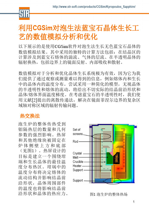
热交换法泡生炉的整体传热受到钼隔热层的数量和几何参数的强烈影响。
热屏和其他绝缘块被固定在炉体侧壁上方和底部(见图1)。
热屏设计的目标是建立一个围绕坩埚和生长晶体的最佳温度分布热区。
坩埚中的温度分布将决定熔体的流动结构并影响结晶前沿形状,晶体周围部件的温度也将影响结晶前沿形状和晶体的热应力。
图1 泡生炉的整体热场模拟验证利用现有的实验数据对模拟进行了验证。
模拟成功地再现了实验中观察到的轮辐状模式,如图2所示。
图2 三维非稳态模拟预测的熔体自由表面温度分布(右)和实际熔体表面照片(左,照片由Crystal Development Company, Moscow提供)图3(右图)示出通过模拟预测的结晶形状与实验观察的一致性,表明模拟结果准确反应了晶体和熔体中的温度和热通量,这确保了对于在晶体中引起位错的热应力的模拟预测。
工业应用实例改进泡生炉的热区,以减少结晶前沿的热梯度,带来了更高的产率和更好的晶体质量。
使用CGSim软件模拟,考虑炉体的几种不同结构[1]。
在最初的结构,熔体流动有两个旋涡(模型1)。
较大涡占据熔体的核心区,较小涡在横向生长阶段靠近熔体自由表面,在圆柱形生长阶段消失,如图4和图5。
晶体生长建模软件FEMAG--Numerical Prediction of Bulk Crystal Defects
晶体生长建模软件FEMAGOptimization of Silicon I n go t Q ual it yby the Numerical P r e d i c ti on of Bulk Crystal D e f ec t sF. Loix2*, F. D upr e t1,2*, A. de Potter2, R. R ol i n s ky2, W. L i a ng2, N. Van den Boga e rt21CESAME Rese a r ch C e nt e r, Uni v e r s i técatho li que de L ouva i n,Bât i m e nt EULER, 4 av. Georges L e maît r e,B-1348 Louva i n-l a-N e uv e,B e l g i um2FEMAGSoft S.A. Company, 7 Rue André Dumont, Ax i s Parc, B-1435 Mont-Saint-Guibert, B e l g i um The growth of S ili c on(Si) i ngot s by the Czoc hra l s ki (Cz) technique for e l ec t roni c (IC) a ppl i ca t i ons has been governed for more than 50 years by two, somewhat c ont ra di c t ory, t ec hnologi ca l obj ec t i ve s. First, the c rys t a l diameter has to be nearly constant and the l arge s t pos s i bl e according to current market requirements. Second, the product quality has to be pe rfe c t l y c ont rol l e d in terms of c rys t a l defects and composition. On the other hand, grow i ng Cz S i c rys t a l s for photo-volt a i c(PV) a ppl i ca t i ons requires to m i ni m i ze both the energy cons umpt i on and the growth dura t i on without, however, genera t i ng a too l arge content of m i c ro-voi ds in the c rys t a l.A c hi e vi ng these goa l s i s by no means easy s i nc e i nc rea s i ng the c rys t a l diameter re qui re s a l arge r m e l t volume and hence results in a much more complex m e l t flow regime with c om pl i ca t e d heat, momentum and s pec i e s transport effects, a very s ens i t i ve s ol i d-li quid i nt e rfa ce shape (with a l e ss uniform t he rm a l gradient), and in genera l an enhanced dynamic s ys t e m behavior. A s i m il a r enhancement of the system dynam i c behavior can result from the use of a high pull rate to i nc rea s e the growth speed. Therefore, in genera l,de s i gning the furnace hot zonewill require to i ntroduc e appropriate heat s hi e l ds in order to w e ll-cont rol the ra di a t i on hea t transfer whi l e a s a t i s fa c t ory m e l t flow pattern can only be obt a i ne d for l arge diameter c rys t a l s by the ac t i on of transverse or configured m agne t i c fi e l ds.Moreover the s e l ec t i on of opt i m a l proc e ss parameters (heater power, c rys t a l pulling rate, c rys t a l and c ruc i bl e rot a t i on rates, m agne t i c fi e l d i nt ens i ty if any, ambient gas flow rate, etc.) becomes much more difficult in vi e w of the i nc rea s e d system nonl i nea rity and t i m e-depende ncy,e s pec i a ll y during the c rit i ca l process stages (necking, shouldering, t a il-e nd stage, c rys t a l detachment, …).N one t he l e ss,compared to the high difficulty to address these different t ec hnologi ca l i ss ue s,it i s worth observing that huge progress has been achieved in the l a s t decades in s e ve ra l s c i e nt i fi c dom a i ns.F i r s t, the phys i c s of ra di a t i on and c onve c t i on in Cz furnaces, and of defect form a t i on and transport in growing S i c rys t a l s,i s much better known, and hence the m a t he m a t i ca l m ode l s governing Cz S i c ry s t a l growth are better and better e s t a bl i s he d.In spite of the i mport a nt i mprovem e n t s that re m a i n necessary in the m ode li ng of turbulence in the m e l t a nd the ambient gas (i nc l uding the m ode li ng of m e l t turbulence under the effect of a m agne t i c fi e l d) and of the s t ill i ns uffi c i e nt kno w l edge of the m a t e ri a l parameters governing point-and micro-defect e vol ut i on in S i s i ngl e c rys t a l s,an a l m os t complete picture of the phy s i c s of S i growth today i s a va il a bl e.Secondly, num e ri ca l methods and computers have a l s o quickly progre ss e d s i nc e the de ve l opm e n t of the first m ode l s of Cz growth achieved in the 1980’s. Nowadays the qua s i-s t ea dy or t i m e-depende nt s i m ul a t i on of the Cz process hasbecome po ss i bl e in an acce pt a b l e c omput i ng t i m e,with s uffi c i e nt l y refined meshes to resolve the key de t a il s of the problem, and with appropriate num e ri ca l techniques to handle the system de form i ng ge om e try (which comprises s e ve ra l moving components together with free boundaries such as the m e l t-c rys t a l and m e l t-ga s i nt e rfa ce s).Therefore, having at one’s di s posa l the appropriate phys i ca l m ode l s, num e ri ca l tools a nd computer hardware, the route i s directly opened to process opt i m i za t i on by means of num e ri ca l s i m ul a t i on.The obj ec t i ve of the present paper i s to ill us t ra t e how this strategy can be a ppl i e d by use of the FEMAG-CZ software as today co-de ve l ope d by FEMAG Soft S.A. Company and the CESAME research center of the Uni ve rs i téde L ouva i n (Belgium).We will here focus on the S i ingot quality pre di c t i on and i t s opt i m i za t i on.We present a fully t i m e-depende nt m ode l devoted to predict the gl oba l heat transfer in the furnace, the s ol i d-liquid i nt e rfa ce shape, and the re s ult i ng di s tri but i ons of point-and m i c ro-de fe c t s as ca l c ul a t e d from the S i nno-Dornbe rge r (S-D) model together with an e xt ens i on of the l um pe d model of Voronkov and Kulkarni. All the t rans i e nt s are cons i dere d including the effects of c rys t a l a nd c ruc i bl e lift, of the heat capac i t i e s of the furnace cons t i t ue nt s, of the t he rm a l i ne rt i a of the s ol i di fi ca t i on front, and of the dynam i c defect governing l a w s.We hence show that dynamic effects deeply affect the defect di s tri but i on in the c rys t a l(fig 1.). In a ddi t i on to the c l a ss i ca l point-defect e vol ut i on mechanisms, a new l um pe d m ode l i s de ve l ope d to ca l c ul a t e theform a t i on a nd growth of m i c ro-de fe c t s in order to predict their dens i t i e s and s i ze di s tri but i ons anywhere in the c rys t a l.Another key i ss ue in Cz S i growth i s to control the dens i ty of oxygen and any other s pec i e s(i nc l uding dopants and i mpuri t i e s) i ns i de the c rys t a l. M ode li ng i ss ue s will be here aga i n de t a il e d.Finally, off-line process control pri nc i pl e s will be addressed. Results will ill us t ra t e how this tool can he l p in opt i m i z i ng c rys t a l shape and quality.P r e di c t e d defect de l t a C i-C v di s t r i bu t i on (C i, C v be i ng the conc e nt r at i on of i n t e r s t i t i al s , vacanc i e res p e c t i v e l y) with a quas i-s t e ady (a) and a t i me-d e pendent (b)simulation. The OSF ring is located at the position where delta~= 0. This picture highlights the strong impact on the point defect of the transient effects in the growing crystal.。
全球半导体晶体生长仿真著名商业软件FEMAG--Optimization of Silicon Ingot Quality

全球半导体晶体生长仿真著名商业软件FEMAGOptimization of Silicon I n go t Q u al it yby the Numerical P r e d i c ti on of Bulk Crystal D e f ec t sF. Loix2*, F. D upr e t1,2*, A. de Potter2, R. R ol i n s ky2, W. L i a ng2, N. Van den B oga e rt21CESAME R e s e a r ch C e nt e r, Uni v e r s i téc at ho li que de L ouva i n,Bât i m e nt EULER, 4 av. Georges L e m aît r e,B-1348 Louva i n-l a-N e uv e,B e l g i um2FEMAGSoft S.A. Company, 7 Rue André Dumont, A x i s Parc, B-1435 Mont-Saint-Guibert, B e l g i umThe growth of S ili c on(Si) i ngot s by the Cz oc hra l s ki(Cz) technique for e l e c t roni c (IC) a ppl i c a t i ons has been governed for more than 50 years by two, somewhat c ont ra di c t ory, t e c hnol ogi c a l obj e c t i ve s.First, the c rys t a l diameter has to be nearly constant and the l a rge s t pos s i bl e according to current market requirements. Second, the product quality has to be pe rfe c t l y c ont rol l e d in terms of c rys t a l defects and composition. On the other hand, grow i ng Cz S i c rys t a l s for phot o-volt a i c(PV) a ppl i c a t i ons requires to m i ni m i z e both the energy c ons umpt i on and the growth dura t i on without, however, gene ra t i ng a too l a rge content of m i c ro-voi ds in the c rys t a l.A c hi e vi ng these goa l s i s by no means easy s i nc e i nc re a s i ng the c rys t a l diameter re qui re s a l a rge r m e l t volume and hence results in a much more complex m e l t flow regime with c om pl i c a t e d heat, momentum and s pe c i e s transport effects, a very s e ns i t i ve s ol i d-li qui d i nt e rfa c e shape (with a l e ss uniform t he rm a l gradient), and in gene ra l an enhanced dynamic s ys t e m behavior. A s i m il a r enhancement of the systemdyna m i c behavior can result from the use of a high pull rate to i nc re a s e the growth speed. Therefore, in gene ra l,de s i gni ng the furnace hot zone will require to i nt roduc e appropriate heat s hi e l ds in order to w e ll-c ont rol the ra di a t i on he a t transfer whi l e a s a t i s fa c t ory m e l t flow pattern can only be obt a i ne d for l a rge diameter c rys t a l s by the a c t i on of transverse or configured m a gne t i c fi e l ds.Moreover the s e l e c t i on of opt i m a l proc e ss parameters (heater power, c rys t a l pulling rate, c rys t a l and c ruc i bl e rot a t i on rates, m a gne t i c fi e l d i nt e ns i ty if any, ambient gas flow rate, etc.) becomes much more difficult in vi e w of the i nc re a s e d system nonl i ne a ri ty and t i m e-depe nde nc y,e s pe c i a ll y during the c ri t i c a l process stages (necking, shouldering, t a il-e nd stage, c rys t a l detachment, …).N one t he l e ss,compared to the high difficulty to address these different t e c hnol ogi c a l i ss ue s,it i s worth observing that huge progress has been achieved in the l a s t decades in s e ve ra l s c i e nt i fi c dom a i ns.F i r s t, the phys i c s of ra di a t i on and c onve c t i on in Cz furnaces, and of defect form a t i on and transport in growing S i c rys t a l s,i s much better known, and hence the m a t he m a t i c a l m ode l s governing Cz S i c ry s t a l growth are better and better e s t a bl i s he d.In spite of the i mport a nt i m prove m e n t s that re m a i n necessary in the m ode li ng of turbulence in the m e l t a nd the ambient gas (i nc l udi ng the m ode li ng of m e l t turbulence under the effect of a m a gne t i c fi e l d) and of the s t ill i ns uffi c i e nt kno w l e dge of the m a t e ri a l parameters governing point-and micro-defect e vol ut i on in S i s i ngl e c rys t a l s,an a l m os t complete picture of the phy s i c s of S i growth today i s a va il a bl e.Secondly, num e ri c a l methods and computers have a l s o quickly progre ss e d s i nc e the de ve l opm e n t ofthe first m ode l s of Cz growth achieved in the 1980’s. Nowadays the qua s i-s t ea dy or t i m e-depe nde nt s i m ul a t i on of the Cz process has become po ss i bl e in an a cc e pt a b l e c om put i ng t i m e,with s uffi c i e nt l y refined meshes to resolve the key de t a il s of the problem, and with appropriate num e ri c a l techniques to handle the system de form i ng ge om e try (which comprises s e ve ra l moving components together with free boundaries such as the m e l t-c rys t a l and m e l t-ga s i nt e rfa c e s).Therefore, having at one’s di s pos a l the appropriate phys i c a l m ode l s, num e ri c a l tools a nd computer hardware, the route i s directly opened to process opt i m i z a t i on by means of num e ri c a l s i m ul a t i on.The obj e c t i ve of the present paper i s to ill us t ra t e how this strategy can be a ppl i e d by use of the FEMAG-CZ software as today co-de ve l ope d by FEMAG Soft S.A. Company and the CESAME research center of the Uni ve rs i téde L ouva i n (Belgium).We will here focus on the S i ingot quality pre di c t i on and i t s opt i m i z a t i on.We present a fully t i m e-depe nde nt m ode l devoted to predict the gl oba l heat transfer in the furnace, the s ol i d-liquid i nt e rfa c e shape, and the re s ult i ng di s t ri but i ons of point-and m i c ro-de fe c t s as c a l c ul a t e d from the S i nno-D ornbe rge r (S-D) model together with an e xt e ns i on of the l um pe d model of Voronkov and Kulkarni. All the t ra ns i e nt s are c ons i de re d including the effects of c rys t a l a nd c ruc i bl e lift, of the heat c a pa c i t i e s of the furnace c ons t i t ue nt s, of the t he rm a l i ne rt i a of the s ol i di fi c a t i on front, and of the dyna m i c defect governing l a w s.We hence show that dynamic effects deeply affect the defect di s t ri but i on inthe c rys t a l(fig 1.). In a ddi t i on to the c l a ss i c a l point-defect e vol ut i on mechanisms, a new l um pe d m ode l i s de ve l ope d to c a l c ul a t e the form a t i on a nd growth of m i c ro-de fe c t s in order to predict their dens i t i e s and s i z e di s t ri but i ons anywhere in the c rys t a l.Another key i ss ue in Cz S i growth i s to control the dens i ty of oxygen and any other s pe c i e s(i nc l udi ng dopants and i m puri t i e s) i ns i de the c rys t a l.M ode li ng i ss ue s will be here a ga i n de t a il e d.Finally, off-line process control pri nc i pl e s will be addressed. Results will ill us t ra t e how this tool can he l p in opt i m i z i ng c rys t a l shape and quality.P r e di c t e d defect de l t a C i-C v di s t r i bu t i on(C i,C v be i ng the c onc e nt r at i on ofi n t e r s t i t i al s , v acan c i e re s p e c t i v e l y) with aquas i-s t e ady (a) and a t i m e-d e pendent (b)simulation. The OSF ring is located at theposition where delta~= 0. This picturehighlights the strong impact on the pointdefect of the transient effects in the growing crystal.。
##加热温度对GOI法生长蓝宝石晶体影响的数值模拟
第25卷第4期 硅 酸 盐 通 报 Vol .25 No .4 2006年8月 BULLETI N OF T HE CH I N ESE CERAM I C S OC I ETY August,2006 加热温度对G O I 法生长蓝宝石晶体影响的数值模拟许承海,杜善义,孟松鹤,左洪波,张明福(哈尔滨工业大学复合材料研究所,哈尔滨 150001)摘要:利用数值模拟分析方法,模拟了通过调节加热温度促进G O I 法蓝宝石晶体生长的过程。
分析了加热温度变化对晶体生长的固液界面凸出率、晶体内温度分布、温度梯度的影响;热交换器散热参数与加热温度之间的关系。
结果表明,在G O I 法蓝宝石晶体生长中,合适的降温控制程序有利于提高晶体生长质量,晶体生长速率会随着加热温度的降低而快速增加。
在相同降温程序下,较大的热交换器散热能力具有较快的晶体生长速率;低的热交换器散热能力和加热温度有利于降低晶体生长的界面凸出率。
关键词:加热温度;数值模拟;蓝宝石;G O I 法Num er i ca l S i m ul a ti on of Hea ter Tem pera ture Effect onSapph i re Cryst a l Growth w ith GO IM ethodXU Cheng 2hai,DU Shan 2yi,M EN G Song 2he,ZUO Hong 2bo,ZHAN G M ing 2fu(Center for Composite Materials,Harbin I nstitute of Technol ogy,Harbin 150001)Abstract:Nu merical analysis was used t o si m ulate the p r ocess of sapphire crystal gr owth by modulating te mperature .The influences of te mperature πs change in heat syste m on the convexity of the s olid 2melt interface,te mperature distributi on and te mperature gradient of crystal inside were analyzed .The relati on bet w een ther mal convecti on coefficient of ther mal exchanger and te mperature in heat syste m was discussed .The results show that during the gr owth of crystal with G O I method p r oper p r ogra m of te mperature contr ol is good f or the quality of crystal .Lo wer te mperature can greatly accelerate gr owth of crystal .I n the sa me p r ocess of te mperature fall,the l ower radiating ability of ther mal exchanger and l ower te mperature has advantages on reducing the convexity of the crystal gr owth interface .Key words:heater te mperature;nu merical si m ulati on;sapphire;G O Imethod作者简介:许承海(19782),男,博士研究生.主要从事G O I 法大尺寸蓝宝石单晶生长与数值模拟分析方向的研究. 蓝宝石(α2A l 2O 3)又称白宝石,俗称刚玉,其具有一系列独特的物理、化学、机械和热特性[1,2]。
全球半导体晶体生长建模著名商业软件FEMAG 横向磁场直拉硅晶体生长的全局模拟 优质课件

FEMAGSoft © 2013
Cz Si growth under a TMF (cont’d)
Flow and global heat transfer in a silicon Cz puller
under the effect of a TMF (quasi-steady simulation)
Main modeling hypothesis:
- the viewed and hidden parts are calculated as axisymmetric
- or, equivalently, each surface of the enclosure is viewed as axisymmetric from the other surfaces
dH = L Ha-1 (L = Rs or Rc). Typically dH = 0.05 - 0.08 mm in industrial furnaces.
FEMAGSoft © 2013
Cz Si growth under a TMF (cont’d)
Transverse magnetic fields: FLET method
Bottom: velocity field magnitude and crosssection showing a sharp Hartmann layer along the melt-crucible interface.
FEMAGSoft © 2013
Cz Si growth under a TMF (cont’d)
Hypothesis:
Objective: global, quasi-steady or time-dependent calculations at a reasonable cost
全球半导体晶体生长仿真著名商业软件FEMAG--Numerical Simulation of Bulk Crystal Growth
Introduction (cont’d)
General objective of FEMAGSoft
• FEMAG-2 → FEMAG-3 software generation transition taking place from 2008-2009
→ strongly improved platform in terms of computation time, memory, etc.
FEMAGSoft © 2013
Introduction (cont’d)
Solving these problems requires …
• To develop a sound physical model for each separate effect
→ global and time-dependent modeling of heat transfer, turbulence modeling, defect modeling, …
Analysis of conical growth and shouldering stages m = 8.225 10-4 kg/m.s Wc= 3.82 rpm (0.4 s-1) Ws= -3.82 rpm (-0.4 s-1) Vpul = 1.8 cm/h (5. 10-6 m/s)
FEMAGSoft © 2013
1. Numerical strategy (cont’d)
FEMAG-1 timedependent simulation of Czochralski Ge growth
Direct dynamic simulation (imposed stepwise decrease of heater power, calculated crystal shape): evolution of the temperature field
晶体生长建模软件FEMAG介绍(八)--FEMAGPVT(物理气相传输法)
晶体⽣长建模软件FEMAG介绍(⼋)--FEMAGPVT(物理
⽓相传输法)
FEMAG/PVT软件的主要功能
FEMAG/PVT软件⽤于模拟物理⽓相传输法(Physical Vapor Transport process,PVT)晶体⽣长⼯艺,可以⽤于碳化硅单晶体、氮化铝、氧化锌多晶体等的PVT法⽣长⼯艺过程的模拟。
FEMAG/PVT软件的典型应⽤
FEMAG/PVT软件的典型应⽤是模拟碳化硅单晶的PVT法⽣长过程。
图1是碳化硅晶⽚。
碳化硅(SiC)是⼀种优质的宽带隙半导体材料,具有宽禁带、⾼击穿电场、⾼热导率、⾼饱和电⼦漂移速率等优点,可以满⾜⾼温、⼤功率、低损耗⼤直径器件的需求。
SiC单晶⽆法经过熔融法形成,⽽基于改进型Lely法的升华⽣长技术——物理⽓相传输法是获得SiC单晶的常⽤⽅法。
PVT法制备SiC单晶的⽣长原理是:⾼纯SiC粉源在⾼温下分解形成⽓态物质(主要为Si、SiC2、Si2C),这些⽓态物质在过饱和度的驱动下,升华⾄冷端的籽晶处进⾏⽣长。
过饱和度是由籽晶与粉源之间的温度梯度引起的。
图2是利⽤FEMAG/PVT软件计算碳化硅沉积腔内的温度梯度的结果。
FEMAG晶体生长模拟软件之Float_Zone_Process_(FEMAG-FZ)
FEMAG晶体生长模拟软件Float Zone Process (FEMAG-FZ)FEMAG区熔法软件(FEMAG-FZ)用于模拟区熔法生长工艺(FZ, PFZ)FEMAG区熔法软件专注于设计新的热场,并研发新的方法以满足新的商业需求点,比如:✓无缺陷晶锭生长✓提高成品率✓节省R&D成本FEMAG区熔法软件因为降低了试验成本而显著节省研发费用。
区熔法工艺的等温线预测无缺陷晶锭生长无缺陷晶体硅生长是世界上最大的难点之一。
FEMAG模拟软件能够帮助工程师运用自己独一无二的技术生长出无缺陷晶体。
半导体晶体缺陷决定了晶锭的市场价格。
通过FEMAG软件的缺陷工程模块,晶体生长行业工作者能够轻松预测晶体炉中生长的晶体质量。
缺陷工程模块能够洞悉硅、锗生长过程中填隙原子,空位和微孔演变过程。
FEMAG-FZ能够成为你的测试平台,试验在不同的操作条件下对于晶体生长质量的影响,如✓热场设计✓晶体和馈送棒的旋转速率✓晶体提拉速度,馈送棒的推送速度一旦研究出上述的依赖关系,就能够控制工艺过程,获得最理想而省时的晶体生长条件。
FEMAG预测区熔法生长晶体缺陷提高成品率您曾经考虑过是什么限制了您的晶体生长生产潜力以达到最大产量吗?您知道这些限制因素对产出的影响吗?FEMAG区熔法模拟软件可以帮助您在晶体生长过程的每一个时刻追踪关键参数的变化。
区熔法模拟软件为工程师们提供了在晶体生长过程中凝固前沿形状,热弹性应力,溶体流动形态等信息。
FEMAG FZ模块的用户可以通过上述的参数信息优化其工艺条件,从而增加凝固生产效率和产出。
节省R&D成本FEMAG区熔法模拟软件能够降低您的研发成本,区熔法生长的领先用户擅于使用FZ模拟软件来减少实验成本并增加投资回报。
这些模拟工作旨在复现固液界面的实验结果,并将数值模拟的结果与晶锭的光扫描观测结果进行对照。
模拟晶体转速对熔体流动的影响。
晶体生长计算软件FEMAG浮区法生长晶体方法
FEMAGSoft © 2011
2. A global simulation tool (cont’d)
Induction Heating in FZ semi-conductor growth
Conduct or
d B
Dissipated power:
Force density:
Alternating magnetic field effects : 1) Heat flux
1. Introduction 2. Global simulation tool
3. Simulation examples
4. Discussion
FEMAGSoft © 2011
2. A global simulation tool
Typical FEMAG-FZ global unstructured mesh for heat transfer and induction heating
FEMAGSoft © 2011
2. A global simulation tool (cont’d)
Prediction of Crystal Defects
FEMAGSoft © 2011
2. A global simulation tool (cont’d)
Quasi-steady simulation of the growth of a 100 mm silicon crystal
Growth of a 100 mm silicon crystal
(1mm/min pull rate) Predicted defect delta -(CI-CV) distribution by means of a quasi-steady simulation
- 1、下载文档前请自行甄别文档内容的完整性,平台不提供额外的编辑、内容补充、找答案等附加服务。
- 2、"仅部分预览"的文档,不可在线预览部分如存在完整性等问题,可反馈申请退款(可完整预览的文档不适用该条件!)。
- 3、如文档侵犯您的权益,请联系客服反馈,我们会尽快为您处理(人工客服工作时间:9:00-18:30)。
蓝宝石晶体生长数值模拟方案
2
蓝宝石晶体生长数值模拟方案
一、工业蓝宝石晶体生长现状
蓝宝石以其晶莹剔透的美丽颜色,自古就被蒙上神秘的超自然的色彩。在现代人眼中,蓝宝石也
是被大众所喜爱的珍贵装饰物。在工业上,蓝宝石是除金刚石以外,硬度最高的天然材料,而且耐磨、透
光性好,具有多种光学、机械、电气、热以及化学特性,因此还被广泛应用于工业等多种领域。蓝宝
石不仅是军用车辆透明装甲的材料,也是下一代手机等电子产品屏幕,LED 等电子器件和衬底的主要
材料。用蓝宝石制成的手机屏幕,除了金刚石以外,任何其他天然物品都无法对其造成破坏和磨损,因此
蓝宝石屏号称“永不磨损”的屏幕。
蓝宝石工业价值很高,可以通过人工生长的方法来获取。工业上常用的蓝宝石晶体熔体生长方法有
直拉法,泡生法,热交换法等。从工艺角度来看,蓝宝石晶体生长涉及到流体,传热,传质等综合物理过
程,生产大尺寸蓝宝石晶体的生长周期长,工艺复杂,而且原材料纯度、处理状态、制备工艺参数等
对晶体质量影响较大,因此晶体生长的成品率不高,对工艺控制的要求很高。
如何低成本、高质量地生长大尺寸蓝宝石单晶已成为当前面临的迫切任务。泡生法是目前最常
用的生长蓝宝石单晶的方法,具有温度梯度小、晶体与坩埚不接触等特点。但生长的蓝宝石晶体常含
有位错、气泡、包裹物、裂隙等缺陷,大大降低了晶体的利用 率。因此,如何低成本、高质量地生
长大尺寸蓝宝石单晶,成为当前企业和研究者们关注的重点。
二、数值模拟的优势
传统改进工艺,提高效益的做法是针对不同工艺参数生长出晶体进行详细的性能测试和微观组织
结构分析,在此基础上给出进一步改进的工艺参数和技术优化措施,并开始下一轮次的晶体生长,来
达到不断修改和优化工艺,获得高质量晶体材料的目的。可见,对于复杂的工艺和难以控制的参数,
这样改进和优化的做法大大拖延了研究生产周期,而且需要耗费巨大的人力物力。
随着高速计算机的迅速发展,数值模拟方法已经发展成为解决实际问题或辅助实际生产的一种
重 要手段。特别是对于生长蓝宝石晶体等复杂的工艺,借助数值模拟的方法来帮助分析可以最大程
度的 提高生产效率,优化产品质量,降低产品成本。
3
三、FEMAG数值模拟方案
FEMAG软件是一套专业的晶体生长模拟软件,其中 FEMAG/CZ 软件是针对直拉法(Cz)而开发的
专用软件,该软件致力于为直拉法晶体生长技术和工艺提供专业的仿真模拟与数据分析,
FEMAG/CZ/OX软件可以用于泡生法的模拟,能够完美分析泡生法生长蓝宝石的过程。FEMAG软件可以
实现包括热场,流场,磁场等在内的多物理场耦合过程的分析,能够分析蓝宝石晶体缺陷,辅助蓝
宝石生长工艺优化等,最大程度地为您或您的企业提供可靠的仿真数据和优化方案。
1、 FEMAG/CZ/OX的技术案例
(1)全局热场模拟
炉体设计对泡生法、直拉法而言,炉体的温度梯度是影响晶体生长质量最关键的因素之一。炉体热
场的合理设计,能够减少能耗,提高晶体的生长质量。FEMAG软件能具有先进的分析算法,够实现炉体
全局热场的模拟、加热器功率的分析以及炉体结构的优化设计等。下图是以直拉法为例,炉体的结构设
计与对应的热场模拟如图1所示。
图1 直拉法炉体设计以及对应的炉体温度场示意图
4
(2)热场流场的分析
FEMAG具有热场、流场的耦合分析功能,能够实现全局的热场以及流场分布分析。图2案例是直
拉法生长蓝宝石热场以及流场模拟的示意图。图3案例是泡生法生长蓝宝石的热场以及流场模拟结果。
图2 直拉法生长蓝宝石热场流场
图3 泡生法生长蓝宝石热场流场
FEMAG软件的算法支持高级的传热模式。例如支持对蓝宝石晶体生长很关键的辐射传热,使得FEMAG
可以修正传统的传热模型,提高模拟的精度。
下面给出的是用准稳态方法模拟直拉法生长40mm蓝宝石的案例,材料参数设置如图4所示,模拟
考虑了辐射传热。图5分别是炉体温度场分布,以及对应的生长区域内熔体和晶体的温度场以及熔体的
流场分布。图6是速度矢量分量图,可以清楚的看到熔体和晶体在提拉生长的整个过程中运动情况。
5
图4 FEMAG/CZ蓝宝石前处理的材料参数设置
图5 炉体热场(上)和晶体生长区域热场流场分布(下)
图6 生长阶段速度矢量分量
分别在熔体或者晶体中考虑辐射传热边界,分析热场与流场并进行对比,可以得到不同的热场与流
6
场结果。考虑了辐射传热边界,热场、流场的模拟结果更精确。
图7 热场模拟;a不考虑热辐射,b只考虑熔体热辐射,
c只考虑晶体热辐射,d同时考虑熔体与晶体热辐射
图7 流场模拟;a 不考虑热辐射,b 只考虑熔体热辐射
c 只考虑晶体热辐射,d 同时考虑熔体与晶体热辐射
(3)先进的网格划分策略
FEMAG/CZ支持对晶体生长炉全局的非结构网格自动生成,同时还针对了磁场作用下磁流体边界层
效应,复杂流动边界层效应等情况,FEMAG特别提供了对BLM边界层网格自动划分的支持,能够很好的
7
适应复杂的结构和边界物理流动层。
图8 (a)整个炉体的非结构网格;(b)关键区域非结构网格;
(c)BLM边界网格沿着熔体边缘分布
下面给出的案例是BLM网格划分策略在蓝宝石泡生法晶体生长中的应用。图9显示了普通网格 与
FEMAG的BLM网格差别。
图9 普通网格(上)与BLM网格(下)的对比
图10、图11分别是在流场与热场模拟中,普通网格与BLM网格结果的差异,图10显示了温度场
分布,图中绿线标定了凝固界面,可以看到在引入了BLM网格之后,凝固界面由平直转为弯曲,与实际
情况更接近。图11显示了相应蓝宝石案例的流场图,引入BLM网格后,模拟结果在边界处有明显的区
别。可见BLM网格极大的提高了模拟精度。
8
图10 温度场模拟对比,(a)普通网格(b)BLM网格
图11 流场模拟对比,(a)普通网格,(b)BLM网格