U4T2SB
初中英语八年级上册重点句子
八年级上册重点句型语法点背诵:U1T11,I often saw you play basketball during the summer holidays.(see sb do sth, see sb doing sth,during)我经常看见你在暑假期间打篮球2,we are going to have a basketball game against Class Three on Sunday.(be going to do sth, against)我们和三班将要在星期天举行一场篮球对抗赛3,I hope our team will win.(will 后接动词原形)我希望我们队获胜4,Would you like to come and cheer us on ?(cheer sb on)你愿意来为我们加油吗?5,which sport do you prefer ,swimming or rowing ?-----I prefer rowing.(prefer 加doing)游泳和划船,你更喜欢哪种运动,我更喜欢划船6,quite a lot经常7,Do you know anything about him?(anything about)你知道任何有关于他的事情吗?8,He played for this job.(play for)他做这份工作9.What are you going to be when you grow up.----I want to be a scientist.(grow up)你长大后想做什么?10,She goes cycling twice a week.(go cycling, twice a day)她一周骑两次自行车11,She spend half an hour exercising in the gym every day.(spend 时间/金钱in doing sth/on sth)她每天花费半个小时在俱乐部锻炼12,she plays it very well.她打得很好13,She is also good at long jump.(be good at ,be good for)她也擅长于跳远14,There is going to be a school sports meet tomorrow.(there is going to be)明天将会有一场校运会。
思亚诺推出SMS4430芯片,用于智能手机和平板电脑

思亚诺推出SMS4430芯片,用于智能手机和平板电脑
以智能手机和平板电脑为市场目标的新型SMS4430还支持IDSB-T (full-seg)、DVB-T和DAB/DAB+
思亚诺推出SMS4430,这是一款为移动/便携式消费电子设备应用设计的新型多标准数字电视接收芯片。
SMS4430是一种比思亚诺SMS4470成本更低、尺寸更小、功耗更低的型号,该公司已出货数百万枚SMS4470接收芯片。
目前,DVB-T2数字电视广播标准扩大了其在东南亚、东欧和西欧、中东、非洲等地区的部署。
ISDB-T已在日本、南美、菲律宾及其它一些国家部署。
SMS4430与ETSI EN 302 755版本1.3.1 (DVB-T2)完全兼容,包括完全支持DVB-T2-Lite;ETSI EN 300 744 V1.6.1 (DVB-T);NorDig unified spec 2.4版;以及ARIB-STD-B31 (ISDB-T)。
它在不同的光谱带上支持1.7、6、7和8 MHz信道带宽:VHF-III (174-240MHz)、VHF-I (47-88MHz)、VHF-II (88-108MHz)、UHF (400-806MHz)和L1 (1.5GHz)。
SMS4430高度集成(包括RF调谐器和相关滤波器——安装于芯片上),并采用7 x 7mm BGA封装。
为了向当今的扩频LTE环境提供扩展的数字电视接收容量,该芯片包含了专有的创新型芯片上NoiseBuster(TM)引擎。
当解调高数据速率DVB-T2信道时,该芯片的功耗仅为220mW。
SMS4430样品面向特定客户提供。
诺瓦科技LED多媒体播放器TB2-4G规格书
S.BUS2端口至S.BUS2端口的接线示例说明书
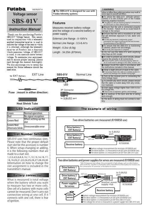
SBS-01VHeat Shrink TubeNormal LineEXT LineSBS-01V V oltage Sensor. This sensor, used in conjunction with a telemetry enabled transmitter/receiver, is used to indicate the voltage of the item to which it is attached. Although the telemetry receiver of Futaba's has a function which measures voltage, if SBS-01V is used, it can measure more battery voltage. To maximize your enjoyment, and to ensure proper sensing, please read through this manual thoroughly. We also encourage you to retain the manual for future reference should the need arise.●The SBS-01V is d esigned for use withFutaba telemetry systems.Green Normal operation Red No signal reception Green/RedWhen setting up the slotGreen/RedAlternate blinkUnrecoverable errorFeaturesMeasures receiver battery voltage and the voltage of a second battery or power supply.External Line Range : 0-100V's Normal Line Range : 3.5-8.4V's Weight : 0.2oz (6.0g) Length : 34.25in (870mm)Please note that the proper default start slot for this accessory is number 6. When setup-changing or adding, it is the following numbers that are made to a start slot.1,2,3,4,5,6,8,9,10,11,12,13,14,16,17,18,19,20,21,22,24,25,26,27,28,29,30Information on how to change the slot assignment is included in the transmitter's manual.when the battery which you want to measure has two or more cells. One cell of a battery with many cells cannot be measured. Don't carry out connection wiring at one cell. If it connects with one cell, there is fear of ignition.Measure the cable and then cut it to the desired length.Cut approximately 30mm of the negative (-, black) line from the cable.Solder the fuse inline on the negative wire and then reattach the section of wire that was previously removed. The fuse should be attached as close to the external power supply as possible.Place a piece of heat shrink tubing over the fuse, ensuring that it covers the soldered areas. Shrink the tubing snug to the fuse and the wire using a heat gun.The cable should be connected as shown in the diagram below. The cable gets connected to the wires that come off the ESC and connect to the battery.The manual for the Telemetry system should be referred to after the setup is complete; checking to make sure it functions as desired and that it provides the correct voltage on the display.Fuse to Black line (-)To MotorFUTABA CORPORATION1080 Yabutsuka, Chosei-mura, Chosei-gun, Chiba-ken, 299-4395, JapanPhone: +81 475 32 6982, Facsimile: +81 475 32 6983©FUTABA CORPORATION 2012, 10 (1)。
NEC TOKIN Corporation UA2 UB2 系列超级紧凑型信号传感器说明书

For Correct Use of Miniature RelaysDO NOT EXCEED MAXIMUM RATINGS.Do not use relays under exceeding conditions such as over ambient temperature, over voltage and over current. Incorrect use could result in abnormal heating, damage to related parts or cause burning. READ CAUTIONS IN THE SELECTION GUIDE.Read the cautions described in NEC/TOKIN's "Miniature Relays" when you choose relays for your application.The information in this document is subject to change without notice.Document No. 0612EMDD03VOL02E Date Published May 2005 P Printed in Japan© NEC TOKIN Corporation 2002Super-compact size, Slim-package, Surface-mounting type availableDESCRIPTIONNEC TOKIN's UA2/UB2 relay ia a new generation miniature signal relay of super-compact size and slim-pakage.FEATURESSmall mounting size of slim package for dense mounting. Telcordia (2500 V) and FCC (1500 V) surge capability.IEC60950/UL1950/EN60950 spacing and high breakdown voltage.(Basic insulation class on 200 V working voltage) Low power consumption 140 mWAPPLICATIONSElectronic switching systems, PBX, terminal equipment, telephone system.Ph (707) 996-5201 Fx (707) 2DIMENSIONS AND PAD LAYOUTS (Unit : mm [inch])UA2 SERIESSTANDARDUB2 SERIESSTANDARDMINIMUM FOOTPRINT TYPEPh (707) 996-5201 Fx (707) e-mail:***************************3PIN CONFIGURATIONS (bottom view)UA2 SERIESUB2 SERIESMARKINGS (top view)Ph (707) 996-5201 Fx (707) e-mail:***************************4PERFORMANCE CHARACTERISTICS (Community)Contact Form2 Form cMaximum Switching Power 30 W (resistive) 37.5 VA (resistive) Maximum Switching Voltage 220 Vdc 250 VacMaximum Switching Current 1 A Contact RatingsMaximum Carrying Current1 AMinimum Contact Ratings 10 mV.dc, 10 µA 4 Initial Contact Resistance 100 m Ω Max. (Initial)Contact MaterialSilver alloy with gold alloy overlay Non-Latch Type140 to 230 mW Nominal Operating Power Single Coil Latch Type100 to 120 mW Operate Time (Excluding Bounce) Approximately 2 msRelease Time (Excluding Bounce) Approximately 1 ms without diode Insulation Resistance 1000 M Ω at 500 VdcBetween Open Contacts Between Adjacent Contacts 1000 Vac for one minute (1500 V surge, 10 × 160 µs 1)Breakdown Voltage Between Coil and Contact1500 Vac for one minute (2500 V surge, 2 × 10 µs 2)Shock Resistance 735 m / s 2(misoperating)980 m / s 2(destructive failure)Vibration Resistance 10 to 55 Hz at double amplitude of 3 mm (misoperating)10 to 55 Hz, double amplitude of 5 mm (Destructive failure) Ambient Temperature - 40 to +85°CCoil Temperature Rise18 degrees at nominal coil voltage (140 mW) 5 × 1073 operations (Non-latch type)No-load1 × 107operations (Latch type)30 Vdc 1 A (resistive), 1 × 10⁵operations at 20°CRunning specificationsLoad125 Vac 0.3 A (resistive), 1 × 10⁵operations at 20°C WeightApproximately 1 grams1 rise time : 10 µs, decay time to half crest : 160 µs2 rise time : 2 µs, decay time to half crest : 10 µs3 This shows a number of operation where it can be running by which a fatal is not caused, and number of operation bywich a stesdy characteristic is maintained is 1 × 10⁷operations. 4This value is a reference value in the resistive load.Minimum capacity changes depending on seitching frequency and enviroment temperature and the load.SAFETY STANDARD AND RATINGTUV Certified (EN61810) UL Recognized (UL508) File No E73266 CSA Certificated(CSA C22.2 No14)File No LR46266No.205059630 Vdc, 1 A (Resistive) 110 Vdc, 0.3 A (Resistive) 125 Vac, 0.3 A (Resistive)Creepage and clearance of coil to contact is overthan 2 mm (According EN60950)Basic insulation classSpacing : UL840Spacing : CSAstd950RECOMMENDED RELAY DRIVE CONDITIONSDrive under condetions. If it is impossible, please inquire to NEC/TOKINNonlatch type Voltage : with ±5% at nominal voltageSingle coil latch type Square pulse (rise and fall time is repidly)pulse height : within ±5% at nominal voltagepulse width : more than 10 msAmbient temperature- 40 to +85°CPh (707) 996-5201 Fx (707) e-mail:***************************5PART NUMBER SYSTEMNOMINAL LINEUPNon-latch Typeat 20°CNominal CoilVoltage(Vdc)Coil Resistance (Ω) ±10 % Must Operate Voltage (Vdc) Must Release Voltage (Vdc) Nominal operate power (mW) 1.5 16 1.13 0.15 140 3 64.3 2.25 0.3 140 4.5 145 3.38 0.45 140 5 178 3.75 0.5 140 6 257 4.5 0.6 140 9 579 6.75 0.9 140 12 1028 9.0 1.2 140 24 2504 18.0 2.4 230Single-Coil Latch Type at 20°CNominal CoilVoltage(Vdc)Coil Resistance (Ω) ±10 % Must OperateVoltage (Vdc) Must Release Voltage (Vdc) Nominal operate power (mW) 1.5 22.5 1.13 1.13 100 3 90 2.25 2.25 100 4.5 202.5 3.38 3.38 100 5 250 3.75 3.75 100 6 360 4.5 4.5 100 9 810 6.75 6.75 100 12 1440 9.0 9.0 100 24 4800 18.0 18.0 120Ph (707) 996-5201 Fx (707) 996-3380e-mail:***************************6PERFORMANCE DATACOIL TEMPERATURE RISETemperature is measured by coil resistance.SWITCHING CAPACITYMAXIMUM COIL VOLTAGEThis is allowed maximum value.Inquiry for NEC/TOKIN under maximum value atcontinuous use.This is a maximum value of permissible alteration.Inquiry for NEC/TOKIN at continuous use..APPLIED VOLTAGE VS. TIMING(Sample: UA2-5NU)Ph (707) 996-5201 Fx (707) e-mail:***************************7OPERATE AND RELEASE VOLTAGE VS. AMBIENT TEMPERATUREThis shows a typical change of operate (release) voltage. Maximum value of operate estimated, so it must be applied more than this value for safety operation. In case of “hot start operation”, please inquiry for NEC/TOKIN.RUNNING TEST (Nonload)(Load: None, Driving: 5V .DC, 50 Hz, 50% duty, Ambient temperature: Room temperature, Sample: UA2-5NU 20 pieces)RUNNING TEST (Load)(Load: 50 V .DC 0.1 A resistive, Driving: 5V .DC, 5 Hz, 50% duty, Ambient temperature: 85 degree C, Sample: UA2-5NU 10 pieces)Ph (707) 996-5201 Fx (707) e-mail:***************************8 BREAKDOWN VOLTAGESample: UA2-5NU 10 piecesALTERNATION OF VOLTAGE AT DENSELY MOUNTING (Magnet interference)Ph (707) 996-5201 Fx (707) 996-3380e-mail:***************************9TUBE PACKAGE (UA2, UB2)Dimensions of Package (Unit : mm)Outline of PackageTAPE PACKAGE (UB2)APPEARANCE TAPE DIMENSIONS mm(inch)Relay orientation mark and tape carrying direction.Ph (707) 996-5201 Fx (707) e-mail:***************************10SOLDERING TEMPERATURE CONDITIONThrough–hole mounting type (UA2)Automatic soldering * Preheating : 100°C max. 1 minute max. * Solder temperature : 260°C max. * Solder time : 5 seconds max. A Manual soldering* Solder temperature : 350°C max. * Solder time : 3 seconds max.Surface mounting type (UB2)IRS MethodNote:1. Temperature profile shows printed circuit board surface temperature on the relay terminal portion.2. Check the actual soldering condition to use other method except above mentioned temperature profiles.Ph (707) 996-5201 Fx (707) e-mail:***************************11U A 2/U B2 SERIES855−60−40−20020Temperature (°C)H u m i d i r y (%R H )40608010080604020NOTES ON CORRECT USE1. Notes on contact load●Make sure that the contact load is within the specified range;otherwise, the lifetime of the contacts will be shortened considerably. Note that the running performance shown is an example, and that it varies depending on parameters such as the type of load, switching frequency, driver circuit, and ambient temperature under the actual operating conditions. Evaluate the performance by using the actual circuit before using the relay.2. Driving relays● If the internal connection diagram of a relay shows + and -symbols on the coil, apply the rated voltage to the relay in the specified direction. If a rippled DC current source is used,abnormalities such as beat at the coil may occur.● The maximum voltage that can be applied to the coil of the relay varies depending on the ambient temperature. Generally,the higher the voltage applied to the coil, the shorter the operating time. Note, however, that a high voltage also increases the bounce of the contacts and the contact opening and closing frequency,which may shorten the lifetime of the contacts.● If the driving voltage waveform of the relay coil rises and falls gradually, the inherent performance of the relay may not be fully realized. Make sure that the voltage waveform instantaneously rises and falls as a pulse.●For a latching relay, apply a voltage to the coil according to the polarity specified in the internal connection diagram of the relay.● If a current is applied to the coil over a long period of time,the coil temperature rises, promoting generation of organic gas inside the relay, which may result in faulty contacts. In this case, use of a latching relay is recommended.● The operating time and release time indicate the time required for each contact to close after the voltage has been applied to or removed from the coil. However, because the relay has a mechanical structure, a bounce state exists at the end of the operating and release times. Furthermore, because additional time is required until the contact stabilizes after being in high-resistance state, care must be taken when using the relay at high speeds.3. Operating environment●Make sure that the relay mounted in the application set is used within the specified temperature range. Use of a relay at a temperature outside this range may adversely affect insulation or contact performance.● If the relay is used for a long period of time in highly humid (RH 85% or higher) environment, moisture may be absorbed into the relay. This moisture may react with the NOx and SOx generated by glow discharges that occur when the contacts are opened or closed, producing nitric or sulfuric acid. If this happens, the acid produced may corrode the metallic parts of the relay, causing operational malfunction.● Because the operating temperature range varies depending on the humidity, use the relay in the temperature range illustrated in the figure below. Prevent the relay from being frozen and avoid the generation of condensation.● The relay maintains constant sealability under normal atmospheric pressure (810 to 1,200 hpa). Its sealability may be degraded or the relay may be deformed and malfunction if it is used under barometric conditions exceeding the specified range.● The same applies when the relay is stored or transported.Keep the upper-limit value of the temperature to which the relay is exposed after it is removed from the carton box to within 50˚C.● If excessive vibration or shock is applied to the relay, it may malfunction and the contacts remain closed. Vibration or shock applied to the relay during operation may cause considerable damage to or wearing of the contacts. Note that operation of a snap switch mounted close to the relay or shock due to the operation of magnetic solenoid may also cause malfunctioning.4. Notes on mounting relays●When mounting a relay onto a PC board using an automatic chip mounter, if excessive force is applied to the cover of the relay when the relay is chucked or inserted, the cover may be damaged or the characteristics of the relay degraded. Keep the force applied to the relay to within 1 kg.● Avoid bending the pins to temporarily secure the relay to the PC board. Bending the pins may degrade sealability or adversely affect the internal mechanism.● It is recommended to solder the relay onto a PC board under the following conditions:<1>Reflow solderingRefer to the recommended soldering temperature profile.<2>Flow solderingSolder temperature: 260˚C max., Time: 5 seconds max.,Preheating: 100˚C max./1 minute max.<3>Manual solderingSolder temperature: 350˚C, Time: 2 to 3 seconds● Ventilation immediately after soldering is recommended.Avoid immersing the relay in cleaning solvent immediately after soldering due to the danger of thermal shock being applied to the relay.● Use an alcohol-based or water-based cleaning solvent. Never use thinner and benzene because they may damage the relay housing.● Do not use ultrasonic cleaning because the vibration energy generated by the ultrasonic waves may cause the contacts to remain closed.5. Handling●Relays are packaged in magazine cases for shipment. If a space is created in the case after some relays have been removed, be sure to insert a stopper to secure the remaining relays in the case. If relays are not well secured, vibration during transportation may cause malfunctioning of the contacts.● Exercise care in handling the relay so as to avoid dropping it or allowing it to fall. Do not use a relay that has been dropped.If a relay drops from a workbench to the floor, a shock of 9,800m/s 2 (1,000 G) or more is applied to the relay, possibly damaging its functions. Even if a light shock has been applied to the relay, thoroughly evaluate its operation before using it.● Latching relays are factory-set to the reset state for shipment.A latching relay may be set, however, by vibration or shock applied while being transported. Be sure to forcibly reset the relay before using it in the application set. Also note that the relay may be set by unexpected vibration or shock when it is used in a portable set.● The sealability of a surface-mount relay may be lost if the relay absorbs moisture and is then heated during soldering.When storing relays, therefore, observe the following points:<1>Please use relays within 12 months after delivery. (Storageconditions : 30 degrees C / 60% RH)<2>For MBB packing, Please use relays within 2 years after delivery.(Storage conditions : 30 degrees C / 60% RH)After opening MBB packing, Please use within 3 months.(Storage conditions : 30 degrees C / 60% RH)Permanent magnets are used in polarized relays.For this reason, when magnet, transformer, or speaker is located nearby, the relay characteristics may change and faulty operations may result.Ph (707) 996-5201 Fx (707) e-mail:***************************UA2/UB2 SERIESNo part of this document may be copied or reproduced in any form or by any means without the prior written consent of NEC/TOKIN Corporation. NEC/TOKIN Corporation assumes no responsibility for any errors which may appear in this document.NEC/TOKIN Corporation does not assume any liability for infringement of patents, copyrights or other intellectual property rights of third parties by or arising from use of a device described herein or any other liability arising from use of such device. No license, either express, implied or otherwise, is granted under any patents, copyrights or other intellectual property rights of NEC/TOKIN Corporation or others. While NEC/TOKIN Corporation has been making continuous effort to enhance the reliability of its electronic components, thepossibility of defects cannot be eliminated entirely. To minimize risks of damage or injury to persons or property arising from a defect in an NEC/TOKIN electronic component, customers must incorporate sufficient safety measures in its design, such as redundancy, fire-containment, and anti-failure features. NEC/TOKIN devices are classified into the following three quality grades:"Standard", "Special", and "Specific". The Specific quality grade applies only to devices developed based on a customer designated "quality assurance program" for a specific application. The recommended applications of a device depend on its quality grade, as indicated below. Customers must check the quality grade of each device before using it in a particular application.Standard: Computers, office equipment, communications equipment, test and measurement equipment,audio and visual equipment, home electronic appliances, machine tools, personal electronic equipment and industrial robotsSpecial: Transportation equipment (automobiles, trains, ships, etc.), traffic control systems, anti-disastersystems, anti-crime systems, safety equipment and medical equipment (not specifically designed for life support)Specific: Aircrafts, aerospace equipment, submersible repeaters, nuclear reactor control systems, lifesupport systems or medical equipment for life support, etc.The quality grade of NEC/TOKIN devices is "Standard" unless otherwise specified in NEC/TOKIN's Data Sheets or Data Books. If customers intend to use NEC/TOKIN devices for applications other than those specified for Standard quality grade, they should contact an NEC/TOKIN sales representative in advance.(Note)(1) "NEC/TOKIN" as used in this statement means NEC/TOKIN Corporation and also includes itsmajorityowned subsidiaries.(2) "NEC/TOKIN electronic component products" means any electronic component product developed ormanufactured by or for NEC/TOKIN (as defined above).DE0202Ph (707) 996-5201 Fx (707) e-mail:***************************。
施耐德PLC说明书

Transparent Ready 是以太网和工业通信技术的成功组合。在这些技术的帮 助下,Premium 可以在任何任务中向您提供最佳的以太网功能:Web 服务 器、发送电子邮件、直接数据库访问、设备同步、I/O 分配等。
3
全方面满足不同控制要求的产品系列
强大的通信功能
每个处理器的前面板均带有: ■ 1个用于编程终端的USB口或串行端口 ■ 1个用于连接到Magelis显示设备的串行端口 ■ 1个用于串行链路、CANopen总线或网络的 PCMCIA插槽。
TSXPAY••
TSXCCY1128
TSXISPY••
TSXWMY100
通信 以太网 TCP/IP AS-Interface CANopen Fipio
Interbus Profibus DP
TSXETY
Uni-Telway
TSXSAY••
TSXCPP110 TSXP57 PCMCIA 卡
Modbus Modbus PLUS Fipway
IPC
控制数据显示器
Data Base
Web 服务器
数据存储 数据处理 数据库访问
网络和通讯卫星
人机对话
软件工具
运动控制
接口和I/O 检测产品
自动化
电机控制
机柜系统
电源
9
控制
通过 Unity 采用一种新的工作方式
更高的标准化和重用水平
■ 与内存无关的非定位符号变量 ■ 结构化数据 ■ 用户块 ■ PLC功能模块,包括程序代码、数据监视表和操作画面 ■ 具有自动版本管理和程序更新功能的库 ■ 导入/导出时的自动重新分配
自动化平台
Modicon Premium
Uports2-ProDriver-64bit-4

Uports2-ProDriver-64bit-4.1.22iCON ProAudio Duo22 Live USB声卡提供音频输入和输出模块,以及与任何智能移动设备的模拟和数字连接,用于直播应用程序。
iCON Pro Audio Duo22 Live是音乐家、制作人和便沿着想要将移动设备整合到其设置中的理想选择。
它具有电脑和移动设备同时连接的特点,使您能够将音频从计算机直接传输到移动设备。
用高端模数转换器在您的电脑或移动设备上创建完美的录音。
高动态范围确保您的表现在最大的细节捕捉。
用电容器或动圈话筒,吉他或贝斯来表达你的想法。
连接扬声器或耳机,使用直接监听,在录音时零延迟地听到自己的声音。
双重连接旨在增强您的移动直播流、播客或视频。
从一个人的节目到一个完整的现场乐队,以超低的延迟直接将您的混音广播到您的移动设备上。
ProDriver 4软件可以让你从电脑上的任何来源重新定向音频,并在没有DAW的情况下托管你最喜欢的VST或Direct X插件。
将你的插件链保存为预设,并在你的会话中调用它们。
(仅限Windows)。
•原始音频:2-in/2-out USB音频接口,配备高级转换器,可进行世界级的24位/192kHz录音和超低延迟混音•实时直播:桌面和移动设备的同步连接,使任何智能手机都可以通过模拟(TRR)和数字(USB-C)连接将音频从计算机实时传输到移动设备,可调的板载输入电平和监控•兼容性:快速USB 2.0连接(总线供电)与Mac和PC兼容•虚拟插件机架:专有的ProDriver 4软件重定向来自计算机上任何源的音频,并支持在没有DAW的情况下托管VST或Direct X插件。
将插件链保存为预设,并在会话期间调用它们(仅限Windows)•经久耐用:坚固的铝结构。
电磁兼容(EMC)设计参考电路

1000pF/2KV FBMA-11-160808-601A10T
1 2 3.3V-Earth
L5
1000pF
C5
C6
1000pF
C1 1000pF
L3
C4 100nF
C3
100nF
C13 1000pF/2KV C14 1000pF/2KV
A
备注: 1、C2、C9、C10、C11 为预设计,根据实际的情况增加,一般不需要增加; 2、C13、C14为预设计,根据实际的情况增加或调整; 3.如防雷等级需要打空接(4、5、7、8)pin,可接上D5做防护。 4.此方案相比中心抽头的方案有了明显的差摸保护。如果要测试绝缘阻抗,请与工程师确认具体的方案。 5.如果4、5、7、8 PIN 不需要测试的话,这部分的器件可以不加
5
3
2
1
千兆网口EMC设计标准电路
D
C1 100nF
1 TCT1 TD1+ TD1-
U1
MCT1 MX1+ MX124 23 22 MX1+ MX1MX1+ MX1MX2+ MX3+ MX3MX2MX4+ MX41 2 3 4 5 6 7 8 MX1+ MX1MX2+ MX3+ MX3MX2MX4+ MX49
MCT3 MX3+ MX3-
18 17 16 MX3+ MX3-
TVS3
BV03C
330R R5 link_o
C4 100nF
10 11 12
TCT4 TD4+ TD4-
MCT4 MX4+ MX4-
15 14 13 MX4+ MX4-
- 1、下载文档前请自行甄别文档内容的完整性,平台不提供额外的编辑、内容补充、找答案等附加服务。
- 2、"仅部分预览"的文档,不可在线预览部分如存在完整性等问题,可反馈申请退款(可完整预览的文档不适用该条件!)。
- 3、如文档侵犯您的权益,请联系客服反馈,我们会尽快为您处理(人工客服工作时间:9:00-18:30)。
U4T2SB
1
Section B
Ⅰ. Material analysis
主活动是1a和3a。1a 通过Kangkang 和Maria 由谈论航天之旅延伸到各自的理想,继续学习一般将来时的被动语态。1b是检测学
生的听力技能,1c通过完成句子,让学生巩固一般将来时被动语态的结构。
Ⅱ.Teaching aims
1. Knowledge aims:
掌握本课的重点词汇和短语,继续学习一般将来时的被动语态。
2. Skill aims:
能够通过1c, 3a和3b环节,基本掌握一般将来时的被动语态的结构。
3. Emotional aims: (optional)
做一个有理想的中学生,并为实现理想而刻苦学习。
4. Culture awareness: (optional)
Ⅲ. The key points and difficult points
Key points:
Words and phrases: realize, dancer, admire, master, take part in, grow up, prefer…to…
Grammar: will +be+pp
2. Difficult points:
I’m excited about the things that will be discovered in the future.
九年级上册教学案例设计
2
Ⅳ. Learning strategies
能够通过2的小秘诀,学习通过问题预测内容的能力。
Ⅴ. Teaching aids
航天员的图片/ UFO图片/录音机/ppt等。
Ⅵ. Teaching procedures
Stage (time period) Interaction
patterns
Teacher activity Student activity Remarks
1 Getting students ready for learning (5mins) Individual work Class activity Step 1: Encourage the Ss to describe what will happen on the earth in 2048. T: Boys and girls, it’s time to check your HMK. Who would like to share your description? T: I’m very glad your imaginations are so wonderful. Step 2: Present some pictures of astronauts to Describe what will happen on the earth in 2048. S1: I think the sky will be crowded with small planes. S2: The housework will be done by robots. S3: The homework will be done on the Internet. S4: … Learn the new words: astronaut,
U4T2SB
3
learn the new words: astronaut, admire, universe. T: Look at the picture. Who are they? T: What do they do? T: Yes. They are all astronauts. They are heroes of our nation. They are admired by many people. Do you want to travel to the universe one day? T: Then, work hard from now on. admire, universe. Ss: They are Liu Yang, Liu Wang and Jing Haipeng. Ss: 航天员。 Ss: Of course.
2 Pre-listening (7mins) Pair work
老师要鼓励学生通
过这些问题来预测
听力材料的内容。
3
While-listening (4mins) Class activity
九年级上册教学案例设计
4
Ⅶ. Blackboard design
I’m excited about the things that will be discovered in the future.
Section B
Words and phrases: astronaut admire universe master realize dance+er=dancer take part in prefer…to… Grammar: will be + pp Sentences:
What are you going to be?
I’d like to be an astronaut when I grow up.
But I prefer science to dance.
Then our dreams will be realized.