WR能量回馈说明书
变频器说明书

U1
1
上海煤科实业有限公司
12
按钮
/
SB1-SB3
3
13
转换开关
LW12-16F/4.5447.2
SW1
1
上海核工双虹电器控制
有限公司
14
转换开关
LW12-16D/4.0518.2
SW2
1
上海核工双虹电器控制
有限公司
15
二极管
FR107
D1-D8
8
深圳市德昌电子有限公司
九、变频器保护功能及故障分析与处理
三、硬件说明
1.外壳结构
a..变频器的隔爆箱外形为直式长方体,上面是接线腔,下面是箱体。箱体内装有变频器功率器件、功率驱动板等器件。接线腔内有12个主接线柱分为两组,A、B、C进线及U1、V1、W1、U2、V2、W2、U3、V3、W3出线,另外还有6个七芯接线柱用来外接传感器信号和远控及工作状态信号,其中4个为本安接线端子。变频控制箱的后侧装散热组件。
2.变频器有两种控制方式:V/f控制和矢量控制
V/f控制方式多用在水泵、风机等不需要很大的起动转矩的场合。
矢量控制多用在提升机、皮带等重载起动,需要很大的起动转矩的场合。
3.保护
下述各种保护,其中任意一种保护动作都可使变频器关断输出,从而保护变频器和电机。
1.过压、欠压
2.过流
3.短路
4.缺相
5.接地
4.端子和导板的连接,请使用接触性好的压接端子。为了防止触电、火灾等灾害事故和降低噪音,必须连接接地端子。接地电缆面积不得小于25平方毫米。
5.接线完毕,请再次检查接线是否正确,有无漏接,端子和导线间是否短路或接地。
6.安装时的所有系统连线必须采用对称性屏蔽电缆,电缆的两端要可靠接地,动力电缆和控制电缆必须分开至少10cm以上,若必须交叉,则动力电缆和控制电缆需垂直布置
DAB方案wRadioW说明书
version v1.0技术支持:KIDY137******** 2019/2/141:概述wRadio-M1是一款集成了DAB/DAB+/FM的多功能模块。
wRadio-m1模块是一款高性能、低成本的针对DAB产品的解决方案,此模块简化了客户的开发过程,很大程度上减少了产品开发时间和开发成本.1.1:特征●全球调频波段(60-108mhz)。
●支持RDS/RBDS。
●支持DAB/DAB+BAND III频率(160-240mhz)。
●支持EQ调节。
●I2S数字音频输出(Optional)。
●支持Service follow/Slide show功能(Optional)。
●支持支驱16Ω或32Ω耳机。
最大输出功率40mW。
●DAB灵敏度大于-96DB.●支持DAB Tick Mark标准.●支持1602,128X32,128X64点阵屏。
支持320X240TFT屏(Optional).●支持SD/USB/BT(Optional).●双闹钟。
贪睡。
●半小时时钟同步。
●U盘升级。
UART升级。
1.2:应用●车载DAB。
车载前装DAB。
●家用DAB收音机。
厨房DAB收音机.●闹钟机,床头柜音箱。
●蓝牙DAB音箱。
●手持DAB设备。
2硬件部分2.1硬件组成wRadio-M1DAB由RF模块与MCU主芯片组成。
其中RF模块包括DAB/FM的前端数据接收。
MCU负责对前端数据处理与解调,同时控制按键.LCD显示。
MCU分两种,一种是M100。
一种是M200.两种MCU的具体差别参考以下表格。
功能M100+RF模块M200+RF模块DAB/DAB+/DLS支持支持FM/RDS支持支持ST7032/ST7025/ST7028支持支持(LCD)TFT彩屏(320X240)不支持支持双闹钟(ALARM1小时)支持支持贪睡(固定9分钟)支持支持SLS(Slide show图片显示)不支持支持BT/SD/USB支持(外挂)支持(外挂)EQ(硬件EQ)支持支持EQ(软件EQ)不支持支持DIMMER支持支持USB升级支持支持UART升级不支持支持多国语言四国语言八国语言(图一)(图二)2.2硬件管脚定义。
好盈电调设置说明书
感谢您购买本产品!无刷动力系统功率强大,错误的使用可能造成人身伤害和设备损坏。
为此我们强烈建议您在使用设备前仔细阅读本说明书,并严格遵守规定的操作程序。
我们不承担因使用本产品而引起的任何责任,包括但不限于对附带损失或间接损失的赔偿责任;同时,我们不承担因擅自对产品进行修改所引起的任何责任。
我们有权在不经通知的情况下变更产品设计、外观、性能及使用要求。
关于售后服务:尊敬的客户,我们的产品自售出之日起,提供180天的保修服务,因此为了保护您的权益,请在购买产品时向销售商索取收据和发票,我们以此作为确定售出日期的凭证。
如无法提供收据或发票,我们将对产品实行有偿维修。
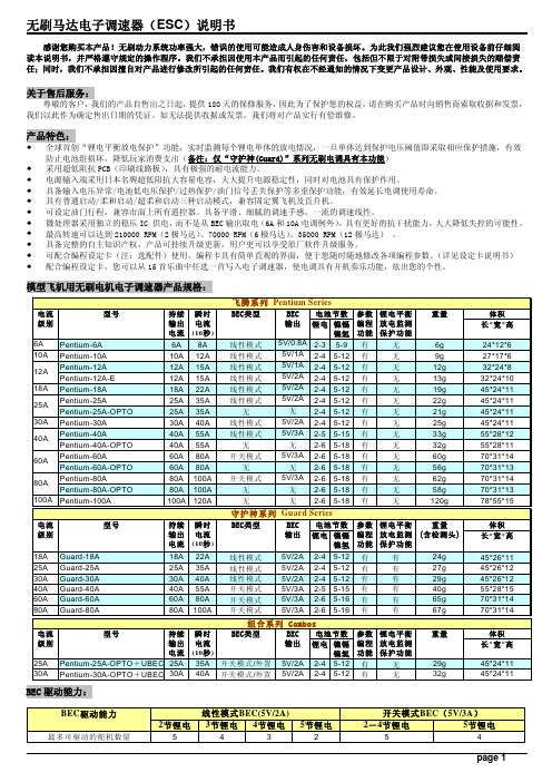
产品特色:全球首创“锂电平衡放电保护”功能,实时监测每个锂电单体的放电情况,一旦单体达到保护电压阈值即采取相应保护措施,有效防止电池组损坏,降低玩家消费支出(备注:仅“守护神(Guard)”系列无刷电调具有本功能)采用超低阻抗PCB(印刷线路板),具有极强的耐电流能力。
电源输入端采用日本名牌超低阻抗大容量电容,大大提升电源稳定性,同时对电池具有保护作用。
具备输入电压异常/电池低电压保护/过热保护/油门信号丢失保护等多重保护功能,有效延长电调使用寿命。
具有普通启动/柔和启动/超柔和启动三种启动模式,兼容固定翼飞机及直升机。
可设定油门行程,兼容市面上所有遥控器。
具备平滑、细腻的调速手感,一流的调速线性。
微处理器采用独立的稳压IC 供电,而不是从BEC输出取电(6A和10A电调例外),具有更好的抗干扰能力,大大降低失控的可能性。
最高转速可以达到210000 RPM(2极马达)、70000 RPM(6极马达)、35000 RPM(12极马达) 。
具备完整的自主知识产权,产品可持续升级更新,用户更可以享受原厂软件升级服务。
可配合编程设定卡(注:选配件)使用,编程卡具有简单直观的界面,便于您随时随地修改各项编程参数。
(详见设定卡说明书) 配合编程设定卡,您可以从15首乐曲中任选一首写入电子调速器,使电调具有开机奏乐功能,炫出您的个性。
ReTurn7500 ReTurn7400 转身杆说明书

75007500i 7400SWL: 150 kg/330 lbsReTurn7500ReTurn7400ReTurn7500, withopening for ReTurnBeltReTurn7500 and ReTurn7400 are used indoors for shorter transfers between wheelchair and bed, wheelchair and toilet/portable toilet/wheelchair or chair/armchair. ReTurn7500 and ReTurn7400 can also be used to aid repositioning farther back in the chair. Both models are designed for easy manoeuvring and use in confined spaces. They are easy to assem-ble and disassemble in just two sections for easier transport and storage. ReTurn7500 is available in two versions. Onemodel has an opening at the upper vertical handle for hooking of ReTurnBelt. ReTurn7400 is lower than ReTurn7500 and is designed mainly for children and short adults.SystemRoMedic is a series of different models of transfer assistive devices. The choice of assistive devices depends on the transfer situation and the patient’s functional capability and needs.Visual inspection Check the condition and function of the product regu-larly. Check to ensure that material is free from damage. If there are signs of wear, the product must be inspect-ed and serviced.Always read the manuals for all assistive devices used during a transfer.Keep the manual where it is accessible to users of the product.Do not leave the patient unattended during a transfer situation.The product should be inspected yearly, and otherwise as required, by a qualified technician. Service must be performed by a qualified technician.A. Push the rising ladder/tube down into the mount-ing fixtures on the chassis, so that the height-adjust-ment buttons are facing towards the caregiver.B. Insert the fixture knobs and tighten. Check to ensure that the fixture knobs are securely tight-ened before using the ReTurn.Assembly • ReTurn is intended for shorter transfers.• Return can only be used on flat floor.• The caregiver must always apply counter pressure in a safe way when the patient is standing up, sitting down and during the actual transfer.Note! Always perform a risk assessment before using ReTurn.Special requirements and conditionsTransport The chassis and raising ladder can be carried separately. Carry the chassis by holding the tube on the front end of the product.Transport, e.g., by car, and storage are easy, since the ReTurn can be disassembled in two pieces.To transfer with ReTurn, the patient must be able to:• support weight while standing• stand up and maintain balance (with support) • grasp handles• understand instructionsNOTE! Increased tipping risk.If ReTurn7400 is used for patients of normal height, it is essen-tial that the patient can support his/her weight while standing and can maintain balance for a prolonged period.ABdown.To release the brake, press on the brake plate so that it resumes its original position (green marking); ensure that the wheels roll freely.Testing standing functionReTurn is ideal for testing a patient’s standing function in cases where there is uncertainty as to whether the patient is able to rise from a seated to a standing position.Training standing functionReTurn can be used to train the patient’s standing, sitting and sit-to-stand function. To measure improvement, use a stopwatch or clock with a second hand to time the patient.TransfersBed to wheelchairPlace the wheelchair at some distance from the bed to allow enough working space. Lock the wheelchair wheels. Place the patient’s feet on the base plate. The patient grasps the raising ladder, leans forward, and then raises himself/herself.Pull the ReTurn back somewhat, and then steer in towards the wheelchair.Position the ReTurn close enough to enable good placement in the wheelchair. The caregiver applies counter pressure before the patient sits down.Adjust the lower-leg support so that the upper edge of the plate is about 3 cm/two fingers below the lower edge of the kneecaps. Pull the two pins to loosen. Adjust to the appropriate height.Ensure that the pins lock securely into place. The lower-leg support can also be adjusted laterally.Farther back in the chairIf the patient slides forward in the wheelchair, the ReTurn can be used to help the patient to slide farther back in the chair.Remove/raise the wheelchair foot plates, and then run the ReTurn in towards the wheelchair. The patient places his/her feet on the foot plate, grasps the raising ladder, leans forward, and then lifts from the seat. The caregiver provides counter pres-sure. Slide the patient farther back in the chair when he/she has lifted slightly from the seat.EnglishBrake the wheels on the ReTurn. The patient then leans forward and g rasps the handles on the ReTurn. The caregivers then grasp the handles on the ReTurnBelt.ReTurnBelt allows different g ripping alternatives, and helps and encourages the patient to lean forward.One caregiver helps the patient to lean forward and pro-vides support during raising.Using ReTurnBelt together with ReTurn7500See manual for ReTurnBelt.ReTurnBelt is used for raising from a seated to a standing position, and for support in the standing position in combination with the use of ReTurn transfer platform. ReTurnBelt has a more rigid lower section for easy application and an elastic up-per section for a better and more comfortable fit. ReTurnBelt has several gripping alternatives and a locking strap for extra support and safety in connection with the use of the ReTurn platform.Two caregivers with ReTurnBeltOne caregiver with ReTurnBeltFasten the clasp without tensioning the strap. A click is heard when the clasp is secured. Brake the wheels on ReTurn.The caregiver encourages the patient to lean forward while providing support during raising by grasping either a handle or the strap.The patient leans forward and grasps the handles on ReTurn.ReTurn7500, with opening on the upper vertical handle:Fasten the clasp on the ReTurnBelt without tensioning the strap. A click is heard when the clasp is secured.When the patient is in a standing position facing the ReTurn, the strap is passed through the opening in the upper vertical handle and placed against the middle support bar (Image 2).Now, transfer the patient with ReTurn. Plan carefully to ensure that the transfer is as short as possible (Image 3).To toilet/shower chairFor transfers to the toilet, space is allowed for the caregiver to assist the patient with the pants. The back also has a small recess that allows the patient to get close to the toilet and achieve a good seated position.Brake the wheels on the ReTurn. Ensure that the patient is standing in a secure position facing the ReTurn, so that the locking strap is loosened. Undo the clasp and remove the strap from the ReTurn. Fold it under the edge of the belt, so that it does not catch on anything. Help the patient into a seated posi-tion with the help of the ReTurnBelt.Sitting downCare of the product:• Use a soft cloth and mild cleaning agent such as dishwashing liquid or car shampoo to clean the ReTurn. Do not use abrasive cloths or brushes to clean the base plate.• Do not use solvents.• To disinfect, use 70% alcohol.EnglishReTurn7500:Do not secure the clasp on the ReTurnBelt before rising. When the patient is in a standing position facing the ReTurn, the strap can be placed around one of the vertical handles.Secure the clasp on the ReTurnBelt. A click is heard when the clasp is secured (Image 1).When it is necessary to attach ReTurnBelt to ReTurn75003。
MAX PATROL 自动收回生命线说明书

MAX PATROL TM SELF RETRACTING LIFELINESComplies with the ANSI Z359.14 standard and OSHA 29 CFR 1910 and 1926 regulations.USER INSTRUCTIONSWerner Co. Fall Protection 724-588-200093 Werner Rd.888-523-3371 toll freeIF YOU HAVE ANY QUESTIONS ABOUT THE PROPER USE OF THE EQUIPMENT , SEE YOUR SUPERVISOR, USER INSTRUCTIONS, OR CONTACT WERNER CO. FOR MORE INFORMATION.GENERAL SAFETY INFORMATIONThese User Instructions are not to be removed except by the user of this equipment. Current User Instructions must always be available to the user.USE INSTRUCTIONS AND LIMITATIONSI MPORTANTBefore use, the user must read and understand these User Instructions. Keep these User Instructions for reference.P URPOSESelf-Retracting Lifelines are designed to be used as part of a complete personal fall arrest system.U SE I NSTRUCTIONS1. Failure to follow all instructions and limitations on the use of the SRL may result in seriouspersonal injury or death.2. Before using a personal fall arrest system, employees must be trained in accordance with therequirements of OSHA 29 CFR 1910.30 and 1926.503 in the safe use of the system and its3. Personal fall arrest and rescue systems, including the SRL, must be inspected prior to each usefor wear, damage, and other deterioration. Defective components must be immediately removed from service in accordance with the requirements of OSHA 29 CFR 1910.140 and 1926.502.4. The complete fall arrest system must be planned (including all components, calculating fallclearance, and swing fall) before using.5. Users must have a rescue plan, and the means at hand to implement it, that provides forthe prompt rescue of the user in the event of a fall, or assures that the user is able to rescue themselves. A fall over an edge may require special rescue measures.6. Store the SRL in a cool, dry, clean environment, out of direct sunlight, when not in use.7. After a fall occurs on the system, immediately remove from service until a “competent person”can make the determination for reuse or disposal.U SE L IMITATIONS1. CAP ACITY: SRL’s are designed for users with a capacity (including clothing, tools, etc.) up to 400lb (181 kg) total working weight.2. CORROSION: Do not leave SRL’s in environments where corrosion of metal parts couldtake place as a result of vapors from organic materials. Use near seawater or other corrosive environments may require more frequent inspections to ensure corrosion damage is not affecting the performance of the product.3. CHEMICAL HAZARDS: Solutions containing acids, alkali, or other caustic chemicals, especiallyat elevated temperatures, may cause damage to the SRL’s. When working with such chemicals, frequent inspection of this equipment must be performed. Contact Werner Co. with any questions concerning the use of the SRL around chemical hazards.4. EXTREME TEMPERATURE: SRL’s are designed to be used in temperatures ranging from -40°Fto +130°F (-40°C to +54°C). Protection should be provided for SRL’s when used near welding, metal cutting or similar activities. Contact Werner Co. with any questions concerning hightemperature environments.5. ELECTRICAL HAZARDS: Use extreme caution when working near high voltage power lines dueto the possibility of electric current fl owing through the SRL or connecting components.6. HEALTH: Minors, pregnant women and anyone with a history of either back or neck problemsshould not use this equipment.7. RESCUE: In the event of a fall over the edge, special rescue measures may be required.8. TRAINING: Do not use SRL’s without proper training from a “competent person” as defi ned byOSHA 29 CFR 1910.140(b) and 1926.32(f).9. REP AIRS: Only Werner Co., or persons or entities authorized in writing by Werner Co., maymake repairs or alterations to the equipment.ANCHORAGE REQUIREMENTSA NCHORAGESAll anchorages to which the SRL attaches must meet the requirements of ANSI Z359.2 and OSHA 29 CFR 1910 and 1926.OSHA states:Anchorages used for attachment of personal fall arrest equipment shall be independent of any anchorage being used to support or suspend platforms and capable of supporting at least5,000 pounds (22.2 kN) per employee attached, or shall be designed, installed, and used as part of a complete personal fall arrest system which maintains a safety factor of at least two; and under the supervision of a qualifi ed person.ANSI Z359.2 states that anchorages selected for fall arrest systems must have a strength capable of sustaining static loads, applied in all permitted directions by the system:A) no less than 5,000 pounds (22.2 kN) for non-certifi ed anchorages; orB) at least two times the maximum arresting force for certifi ed anchorages;C) according to ANSI Z359.6, Specifi cations and Design Requirements for Active FallProtection Systems.When more than one personal fall arrest system is attached to the anchorage, the strength in (A) or (B) must be multiplied by the number of personal fall arrest systems attached to the anchorage. CONNECTION REQUIREMENTSC OMPATIBILITY L IMITATIONSAll connecting subsystems must only be coupled to compatible connectors. OSHA 29 CFR 1910.140 and 1926.502 prohibit snap hooks from being engaged to certain objects unless two requirements are met: snap hook must be a locking type and must be “designed for” making such a connection. Under OSHA “designed for” means that the manufacturer of the snap hook specifi cally designed the snap hook to be used to connect to the equipment in question.The following connections must be avoided because they can result in rollout* when a non-locking snap hook is used:• Direct connection of a snap hook to horizontal lifeline.• Two (or more) snap hooks connected to one D-ring.• Two snap hooks connected to each other.• A snap hook connected back on its integral lanyard.• A snap hook connected to a webbing loop or webbing lanyard.• Improper dimensions of the D-ring, rebar, or other connection point in relation to the snap hook dimensions that would allow the snap hook keeper to be depressed by a turning motion of the snap hook.*Rollout:NO! NCOMPATIBLE ONNECTIONSO FFSET C LEARANCE R EQUIREMENTSEXAMPLE :With the SRL anchored 4 feet above the users D-ring and the user works 2 feet away (offset) from directly overhead (centerline), the required clearance is 6 feet (1.8 m) from the working level to the nearest obstruction below.The required clearance includes; Free Fall and Swing Fall Distance, Harness Stretch, Deceleration Distance and Safety Factor.Not approved for free falls greater than 2 feet.D-ring HeightAbove D-ringBelow D-ring61t .1 7 5 ft (1.5 m)7 f m )(2.7m )11 ft (3.4 )1 4.0 m )1 t(4. )19f t (5.8m )21f t (6.4m )18 f t (5.5 m )20 f t (6.1m )4 f t (4.32 f t .m 1 f t (3.0 m f (2 m )f t(. Do Not Use 17 ft (5.2 m)16 f t (4 17 ft (5.2 m)8(2.104m )85ft t 9 tf)m(3)1f t (35f .9m ).(Do D o N o No N ot ot Us e ses 6m)mo f 51 ft (0.3 m)0 ft (0 m)1 ft (0.3 m)2 ft (0.6 m)3 ft (0.9 m)4 ft (1.2 m)5 ft(1.5 m) 5 ft (1.5 m)4 ft (1.2 m)3 ft (0.9 m)2 ft (0.6 m)3 ft (0.9 m)2 ft (0.6 m)1 ft (0.3 m)0 ft (0 m)-1 ft (-0.3 m)-2 ft (-0.6 m)-3 ft (-0.9 m)-4 ft (-1.2 m)-5 ft (-1.5 m)4 ft (1.2 m)5 ft (1.5 m) 1 ft (0.3 m)0 ft (0 m)1 ft (0.3 m)2 ft (0.6 m)3 ft(0.9 m)4 ft (1.2 m)5 ft (1.5 m)5 ft (1.5 m)4 ft (1.2 m)3 ft (0.9 m)2 ft (0.6 m)3 ft (0.9 m)2 ft (0.6 m)1 ft (0.3 m)0 ft (0 m)-1 ft (-0.3 m)-2 ft (-0.6 m)-3 ft (-0.9 m)-4 ft (-1.2 m)-5 ft (-1.5 m)4 ft (1.2 m)5 ft (1.5 m)OffsetOffsetCenterlineC LEARANCE C ALCULATIONSModel No.Length HousingHousingConnectorLifeline ConstituentLifelineConnectorR43001111 Feet Thermoplastic Steel Carabiner 1 inch Dyneema® / polyester webbing Steel SnapHookR430011-R11 Feet Thermoplastic Steel Carabiner 1 inch Dyneema® / polyester webbing Aluminum RebarHookR430011-SR11 Feet Thermoplastic Steel Carabiner 1 inch Dyneema® / polyester webbingSteel Form HookR41002020 Feet Thermoplastic Steel Carabiner3⁄16 inch galvanized steel cable Steel Swivel Snap HookR41003030 Feet Thermoplastic Steel Carabiner3⁄16 inch galvanized steel cable Steel Swivel Snap HookR41005050 Feet Thermoplastic Steel Carabiner3⁄16 inch galvanized steel cable Steel Swivel Snap HookM ATERIALSH ORIZONTAL S YSTEMSApplications where the SRL is used horizontally or with a horizontal system, the SRL and horizontal system components must be compatible. Both the horizontal and vertical distances are required for clearance calculations. Horizontal systems must be designed and installed under the supervision of a qualifi ed person.These units are suitable for use with horizontal lifelines.OPERATION B EFORE E ACH U SEThe user must read and understand these user instructions, as well as the user instructions for every component and subsystem of the personal fall arrest system.Users must have a rescue plan, and the means to implement it, that provides for the prompt rescue of employees in the event of a fall or assures that employees are able to rescue themselves.Check the operation by pulling smoothly on the lifeline, then pulling sharply on the lifeline to engage the locking mechanism.SRL ’s must be inspected prior to each use. See INSPECTION.C ONNECTIONOn R410 SRLs, attach the housing connector of the SRL to the anchorage or anchorage connector. The opposing end is connected to the dorsal D-ring of the full body harness.PERFORMANCER410020 AND R410030R410050R430011, R430011-R AND R430011-SRSRD Class A (610 mm)(0.6 m)(8 kN)(6 kN)(59 - 141 kg)OSHA 29 CFR1910.140/1926.50242 in (1067 mm)2 ft (0.6 m)1800 lbs (8 kN)N/A400 lbs (181 kg)SRD Class A (610 mm)(0.6 m)(8 kN)(4 kN)(59 - 141 kg)OSHA 29 CFR 1910.140/1926.50242 in (1067 mm)2 ft (0.6 m)1800 lbs (8 kN)N/A400 lbs (181 kg)SRD Class A (610 mm)(0.6 m)(6 kN)(4 kN)(59 - 141 kg)OSHA 29 CFR 1910.140/1926.50242 in (1067 mm)2 ft (0.6 m)1,350 lbs (6 kN)N/A400 lbs (181 kg)On R430 SRLs, attach the housing connector of the SRL to the dorsal D-ring of the full body harness. The opposing end is connected to the anchorage or anchorage connector.For twin leg connections, see applicable twin leg connector user instructions.INSPECTIONF REQUENCYAll components of SRL’s must be inspected prior to each use, and annually by an OSHA defi ned “competent person” other than the user. Local, state, governmental and jurisdictional agencies governing occupational safety may require the user to conduct more frequent or mandatory inspections.C RITERIAAll components of the SRL must be inspected.All markings must be legible and attached to the product.On R410 SRLs, exposed red on the snap hook is the load indicator that the SRL has been subjected to the forces of arresting a fall.On R430 SRLs, white web visible outside the shock pack is the fall indicator and SRL has been subjected to the forces of arresting a fall.Check the operation of the unit by pulling smoothly on the lifeline, then pulling sharply on the lifeline to engage the locking mechanism. Unit must not slip when locked.Housing must be free from cracks, distortion or any other damage.Cable must be inspected for kinks, broken strands, corrosion, abrasion, or other signs of wear and/or damage. Swaged terminations must be secure with the thimble tight and no visible damage.Reserve cable is wrapped in colored tape. Remove from service if colored tape has exited the unit.T o inspect webbing, bend a 6 - 8 inch portion of the webbing into an upside down ‘U’ shape. Continue along all webbing and rope inspecting for tears, cuts, fraying, abrasion, discoloration, burns, holes, mold, pulled or broken stitches, or other signs of wear and damage.All equipment must be free of corrosion, chemical attack, alteration, excessive heating or wear.All snap hooks and carabiners on product must be able to self-close and lock. All hardware must be free of cracks, sharp edges, deformation, corrosion, or any evidence of defect.All components of the fall arrest system must be inspected. See User Instructions supplied with each product.CLEANING, MAINTENANCE AND STORAGEC LEANINGCleaning and maintenance may be performed by the user. The SRL may be wiped down with a mild detergent and clean water solution, and rinsed with a dampened clean cloth to remove detergent. The hardware can also be wiped down to remove grease or dirt with a clean dry cloth.SRL’s requiring maintenance must be tagged “unusable” and removed from service. Do not use any SRL that requires maintenance. Cleaning and maintenance may be performed by the user.Snap hooks may require periodic lubrication. Do not apply oil, grease, or other contaminants on the webbing or cable. Use a dry lubricant that has proper resistance to temperature extremes, moisture, and corrosion. Do not over-lubricate.S TORAGESRL’s should be stored in a cool, dry place out of direct sunlight when not in use. Do not store where damage from environmental factors such as heat, light, excessive moisture, oil, chemicals and their vapors, or other degrading elements may be present.Do not store damaged equipment or equipment in need of maintenance in the same area as product approved for use.Equipment that has been stored for an extended period must be inspected as defi ned in these User Instructions prior to use.LABELSMade in TaiwanMade in TaiwanLABELS CONTINUED11Werner Co. Fall Protection93 Werner Rd. Greenville, P A 16125724-588-2000 • 888-523-3371 toll free • 888-456-8458 fax PN117616-01 ©2018 Werner Co. Rev B 1/19。
pulse egg中文说明书
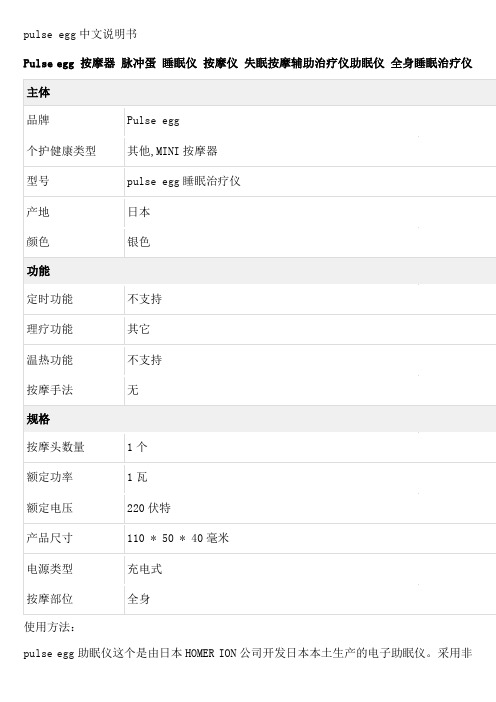
pulse egg中文说明书Pulse egg 按摩器脉冲蛋睡眠仪按摩仪失眠按摩辅助治疗仪助眠仪全身睡眠治疗仪使用方法:pulse egg助眠仪这个是由日本HOMER ION公司开发日本本土生产的电子助眠仪。
采用非药物而是单纯的物理疗法!无任何副作用!操作非常简单,携带方便!“晚上准备入睡时就握于左手,打开开关,调节一个自己舒适的强度。
你会感受到手心酥酥麻麻的一阵一阵。
强度太强的话手心会抽搐的,所以以自己舒适为主。
它会自动计算时间,等你入睡后它会自动关闭。
但其实我也不知道它是啥时候关闭的,因为一会儿就睡着了”1次使用15分钟,大概用100次。
使用次数没有明确的限制,但是不能长时间连续使用 1次使用时间15分钟,连续3次以内为好。
放松模式是可以让你期待得到放松并且心情安定感受的模式振奋模式是可以让你期待得到清醒感受的模式。
睡眠的质量关系到第二的精神状态,希望这宝贝能帮助大家的睡眠质量提升,都能迅速的进入梦乡。
放松模式的话,像是对手掌进行轻轻的咚咚的敲击感,振奋模式的话,开始是轻轻的咚咚的敲击感,慢慢变得很快心跳加速的感觉来回反复。
两种模式1、放松安慰模式(握左手,开关调到:14~73Hz):通过周波递减刺激消除失眠,情绪紧张,烦躁,心跳加快的不良情绪(如开会演讲时紧张,会议报告时紧张,考试前紧张等等)。
2、振奋鼓励模式(握右手,开关调到:14~1Hz):通过周波递增刺激振奋心情,消除工作上受挫失落,没有勇气挑战,自信心不足,抑郁,难过的不良情绪,让您重新打起精神迎接挑战(如面试前恐惧,被上司责骂后失落,比赛时对自己没信心等等的场合)。
缓解极度的紧张感和焦躁情绪,转换各种各样内心的不良情绪。
睡眠安神模式:晚上准备入睡时就握于左手,打开开关,调节一个自己舒适的强度。
你会感受到手心酥酥麻麻的一阵一阵。
强度太强的话手心会抽搐的所以以自己舒适为主。
它会自动计算时间,等你入睡后它会自动关闭。
EzRunWPSC8好盈120A电调说明书
感谢您购买本产品!无刷动力系统功率强大,错误的使用可能造成人身伤害和设备损坏。
我们强烈建议您在使用设备前仔细阅读本说明书,并严格遵守规定的操作程序。
我们不承担因使用本产品而引起的任何责任,包括但不限于对附带损失或间接损失的赔偿责任;同时,我们不承担因擅自对产品进行修改所引起的任何责任。
我们有权在不经通知的情况下变更产品设计、外观、性能及使用要求。
我们的产品提供保修服务,详见网站上的说明(/cn/service.asp?id=1)。
【产品特色】↓一体式全防水及防尘设计(可浸泡在水中工作),特别适合短途卡车、大脚车及其他娱乐性强的车种使用,有效提高电调使用寿命;(注:当需浸水工作时,需将风扇取下,并在使用后尽快将电调冲洗吹干,以免插头氧化生锈)↓独立的编程接口,用参数设定卡调整参数时,不需把接收排线拔下来,更简单方便。
↓EZRUN-WP-SC8内置开关稳压模式(Switching Mode)BEC,具备强大的电流输出能力,即使工作于4S锂电时也无需外挂UBEC;↓底面有安装孔,电调标配安装支架作为附件,便于固定于车架上;↓全新程序算法,具有优异的启动效果(9种启动加速度)、加速性能及油门线性度;↓比例式刹车:5段最大刹车力度调节、8段拖刹力度调节、4段初始刹车力度调节;且兼容传统机械式碟刹系统;↓多重保护功能:电压过低保护(默认支持锂电池和镍氢电池,设置后可以支持所有类型电池)、过温保护、油门失控保护、堵转保护;↓单键编程设定,且有单键恢复默认参数设置的功能;↓可选购轻巧便携的车用电调编程设定卡,方便外场使用,设定卡具有友好的人机界面。
↓可利用LCD编程盒(选配件)上的USB适配器将电调和个人电脑相连,升级电调固件,永久享用最新功能。
【车用无刷电子调速器产品规格】备注1:电调上的散热风扇由内置BEC供电而不是从电池组直接取电,所以使用5V 风扇即可,无需考虑输入电压的高低。
【首次使用车用无刷电子调速器】警告!本系统功率强劲,为安全起见,请在车轮悬空的情况下开启电调上的控制开关!第一步:按下图接线并复查无误后,进入下一步。
Hyper Sport 智能运动设备说明书
O S A F •G O F A S T ER•G OF A S T E R•GO L O NG E R•G O H•G O L O N G ER•G OH Y P ER S P OR T•GO S ME R•G O H Y PE R S PO R T•G O S MA R T ER•G OS A F ER•GH Y P E R S P OR T•GO S MA R T ER•G OS A F ER•G OF A S TE R•GO L O NGGO SMARTERActive intelligent monitoring. At The heart ofevery Hyper Sport Lithium battery is an integratedUTVCORPORATE HEADQUARTERS (USA AND INTERNATIONAL EXCLUDING EMEA) Power-Sonic Corporation7550 Panasonic Way, San Diego, California 92154T:+1 (619) 661 2020F:+1 (619) 661 3650E:********************************POWER-SONIC EUROPE LIMITED (EMEA – EUROPE, MIDDLE EAST AND AFRICA) 3 Buckingham Square,Hurricane Way, Wickford,Essex SS11 8YQT:+44 (0)1268 560686F:+44 (0)1268 560902E:*************************Time (Minutes)05101520253035404550556065 CHARGINGThe battery can be used if the voltage is higher or equalto 12.8V, although we recommend fully charging the battery if the voltage is below 13.0V. Apply constant voltage charge between 14.0V and 15.0V to fully charge the battery.The Hyper Sport series requires lithium compatible chargers and testers. We do not recommend the useof lead acid chargers as many in the market are not suitable for lithium iron phosphate batteries.APPLICATIONS •Motorcycle •Scooter •ATV•Watersport•UTVTime(s)01234567891011WARRANTYDesigned and engineered at our ISO 9001:2001 certifi ed factories all Power Sonic batteries are subject to stringent quality control through every step of the manufacturing process ensuring both consistency and reliability. The Hyper Sport series are backed by a 2-year limited warranty.FURTHER INFORMATIONPlease refer to our website for a complete range of useful tools and downloads, such as our PowerSports battery fi nder, application guides, material safety datasheets and much more.。
好盈WP系列电调用户手册说明书
·全防水设计,适应各种气候环境;(注:浸水工作后尽快将电调洗净吹干,防止插头氧化);·电调内部功率板上覆有好盈专利技术的铜质导热汇流条,便于将内部热量迅速传导到由铝合金材质CNC切削完成的一体化网格状外壳散热器,散热效果更甚一筹;·配备先进安全的电子开关,彻底解决了传统机械式开关在多尘、潮湿等恶劣环境下频发的簧片卡死、触点锈蚀、以及因剧烈撞击而导致机械开关意外关闭等问题;·内置强大的开关模式BEC,持续电流达到3A,瞬间达到6A,且支持 6V和7.4V 切换,轻松驱动各种强力舵机及高压舵机;·非常细腻的拖刹力度以及拖刹加速度调节,满足不同的车型、不同的场地以及不用的操控习惯;·PWM频率可调以及先进的DEO功能,提供更加完美的油门线性以及更出色的操控性能;·9种油门加速度(也叫Punch)调整,从“柔和”到“非常劲暴”,适应不同特性的车型、轮胎及场地;·比例式刹车:9段初始刹车力度调节、9段最大刹车力度调节、9段拖刹力度调节;·多重保护功能:电池低压保护、过温保护、油门失控保护;·具有独立的参数设定接口,连接参数设定卡时无需将电调控制线从接收机中拔出,使用更为方便;·可使用电调上的SET按键设置电调参数,且有单键恢复出厂默认参数的功能;·兼容便携式车用电调编程设定卡(显示屏为数码LED),设定卡具有友好的人机界面,方便外场使用。
故障现象解决方法可能原因1、电池电压没有输入到电调2、电调开关损坏电调油门线插反或通道插错或油门不在中点1、检查电源输入通路是否有焊接不良情况,并重新焊好;2、更换开关。
将电调的油门排线按正确方向插到接收机的“油门(TH)”通道(Throttle,通常为CH2);上电后红色LED闪烁,电机无法启动上电后指示灯不亮,电机无法启动设定卡与电调连通后,按下“RESET”键,然后再按下“OK”保存,即可恢复出厂设置。
海利普HLP-SP100系列说明书(中文版)
132
7.13 简易PLC
133
7.13.1 顺序执行方式
133
7.13.2 并联执行方式
135
第八章 选配件规格
136
8.1 键盘外引安装配件
136
8.1.1 外引键盘通讯电缆
136
8.1.2 键盘外引安装步骤
136
第九章 EMC性能描述
138
9.1 EMC 电磁兼容性
138
9.2 射频干扰开关的使用
内部故障或保护。 ● 请勿自行拆装更改变频器内部连接线或零部件。 ● 严禁私自改装,更换控制板及零部件,否则有触电,发生爆炸等
危险。 ● 请防止儿童或无关人员接近变频器。
1.2 送电中
危险
● 送电中绝不可插拔变频器上的任何连接器(操作面板除外),以 避免变频器损坏并造成人员伤亡。
● 送电前请盖好面盖,以防触电,造成人身伤害。
138
第十章 故障报警及处理 10.1 故障列表 10.2 操作异常及处理
第十一章 日常维护 11.1 注意事项 11.2 变频器存储和运输
HLP-SP100系列
139 139 142 143 143 143
HLP-SP100系列
HLP-SP100系列
第1章 安全使用注意事项
注意 错误使用时,可能造成变频器或机械系统损坏。
HLP-SP100 系列使用说明书
HLP-SP100系列
2.2 产品型号规格
型号
输入电源
输入电 输出电 额定功 适用电 流/A 流/A 率/KW 机/KW
3×380-440V50/60Hz 3.5 HLP-SP1000D7543
3×440-480V50/60Hz 3.0
- 1、下载文档前请自行甄别文档内容的完整性,平台不提供额外的编辑、内容补充、找答案等附加服务。
- 2、"仅部分预览"的文档,不可在线预览部分如存在完整性等问题,可反馈申请退款(可完整预览的文档不适用该条件!)。
- 3、如文档侵犯您的权益,请联系客服反馈,我们会尽快为您处理(人工客服工作时间:9:00-18:30)。
®
能量回馈单元
使用说明书
上海位仁节能科技有限公司
目 录
页 次1. 前言 (2)
1.1 产品简介 (2)
1.2 主要功能及特点 (2)
1.3 应用领域 (2)
1.4 质量保证 (2)
1.5 分解与装配 (2)
1.6 使用须知 (2)
2. 产品检查 (3)
2.1 型号、铭牌说明 (3)
2.2 能量回馈单元外观 (4)
3. 技术规范 (4)
3.1 使用条件 (4)
3.2 技术规范 (5)
4. 接线与安全 (5)
4.1标准接线 (5)
4.2 安装、配线、安全 (6)
5. 保养、维护及存放 (6)
5.1 保养、维护周期 (6)
5.2 保养、维护内容 (6)
5.3 存放 (6)
6. 故障内容、诊断及对策 (6)
1.前言
感谢您选用上海位仁节能科技有限公司研制生产的能量回馈单元!
为了充分发挥能量回馈单元的功能及确保使用者的安全,请详细阅读本使用说明手册。
本手册包括截止至该手册印刷时的最新信息。
本公司全权负责该手册的修订及说明,并保留该手册印刷后更改产品而不另行通知的权力。
本手册中部分图片是示意图,仅供参考,若图片与实物不符,以实物为准。
本手册版权归本公司所有。
当您在使用中发现疑难而本说明书中找不到解答时,请联络本公司,我们的专业人员会竭诚为您服务。
1.1产品简介
上海位仁节能科技有限公司研制生产的能量回馈单元主要由IGBT逆变桥、同步及控制电路等组成。
能量回馈单元将电机制动运行时的发电量逆变回馈电网,弥补了一般通用变频器不能将再生电能逆变回电网的缺陷,保证了变频器运行的安全、节约了能量、同时增强了电机的制动功能。
1.2主要功能及特点
·能量回馈电网,效率最高可达96%,热损耗仅为电阻制动时的4%以下;
·具有输入缺相、输出短路、超温、过压等保护功能及显示,使用安全可靠;
·电压自动跟踪,用户不必自己设定,使用方便;
·噪声过滤,不会污染电网和干扰其他设备;
·具有与上位机通讯功能,可随时进行软件升级更新;
·结构简洁明了,维修保养非常方便。
1.3 应用领域
一般与变频器配合使用。
对于提升机、电梯、油田抽油机等具有再生电能的负载、开、收卷机、辊道等需要快速响应的负载以及离心机等大飞轮惯量负载均适用。
1.4质量保证
质量保证期为一年,当贮存和运输时间超过规定时,则产品使用期限相应地缩短。
具体数值由使用方与承制厂协调决定。
1.5分解与装配
只有在产品发生故障,不分解就不能排除故障的情况下才能分解产品,并用专用工具由承制厂专业技术人员或经过承制厂技术培训合格的
技术人员进行。
1.6使用须知
①请勿对能量回馈单元内部进行耐压测试,这些半导体零件易受高电压
损毁。
②绝不可将三相电源接到能量回馈单元的DC输入端。
③实施配线、检查等作业,必需关闭进线电源。
④保修期内不能自行更改机内连线或更换零部件。
2. 产品检查
每台能量回馈单元在出厂前均做过功能测试,用户在能量回馈单元送达拆封后,安装之前,由于运输过程等原因,务请执行以下检查步骤。
①能量回馈单元铭牌上的型号、编号是否和产品合格证一致。
②能量回馈单元的电源输入端子等是否因运送不慎造成损伤,若有损 伤请勿接入电源。
③螺丝等紧固部分是否有松动,必要时用螺丝刀检查。
如有不良情况,请与本公司业务部门联系。
2.1型号、铭牌说明
· 型号说明
注:订购非标准品,请在合同中说明
• 铭牌资料
能量回馈单元
型号 WR-INV-76XX 出 厂 编 号
直流输入电压 300-760 伏 额定逆变电流 安
交流输入电压 380伏 适用电动机 千瓦 电源相数 3 重量 公斤 上海位仁节能科技有限公司制造
2.2能量回馈单元外观 2.2.1 外观
L L1 W1
W
2.2.2 外形尺寸
型号 W(mm)W1(mm) L (mm)L1(mm)H(mm) REPU-INV-7611~7630202 140 420 400 260 REPU-INV-7655~7675285 210 510 488 310
2.2.3安装尺寸:400 X 140
3.技术规范
3.1 使用条件
·输入交流电源:三相380V ± 10% , 频率:50Hz ± 5%
·环境温度范围:-40 ~ +55℃
·相对湿度 ≤ 85% (+40℃时),海拔高度:≤3500m,可用于高原 ·无腐蚀、无金属粉末、无强烈震动之场合
3.2 技术规范
项目 规范
制动方式 电压自动跟踪方式
反应时间 0.1ms 以下
允许电网电压 340VAC-430VAC , 50Hz
动作电压 ≥600VDC
制动力矩 最大150%
回馈方式 正弦波电流方式
电流畸变 5% 以下
回馈算法 最小谐波PWM 算法
内置电抗器 有
内置噪声滤波 有
设计工作制 长期 (占空比30%)
保护 过热、过电流、过电压、短路、输入缺相 使用电阻 无
防护的等级 IP00
4.接线与安全
4.1 标准接线
4.2安装、配线、安全
①原则上,能量回馈单元安装时,应为立式安装,其接线端子在低端,
以利于散热。
②能量回馈单元内部及其所连接的设备都处于危险的高电压,错误的操
作和不当的安装使用都可能危害生命安全或导致财产损失。
③安装和接线时,必须将与其相连接的变频器和主电源断开,并等待
5-10分钟,变频器内部电容完全放电后才可操作。
※注意:变频器的红色LED指示灯。
这个指示灯亮时,表示内部放电并未完成,不可操作。
5.保养、维护及存放
5.1 保养、维护周期:六个月一次或沙尘暴过后。
5.2 保养、维护内容:
5.2.1停电用电吹风清扫单元箱内的沙尘或积水。
5.2.2 检查能量回馈单元的输入、输出电缆是否有破损、开关螺丝是否有松
动等,如有应紧固。
5.3 存放:本产品在安装前应放于仓库内妥善保管,环境温度:-40~+65℃。
6.故障内容、诊断及对策
故障内容 故障原因 故障检测方法 处理方法
能量回馈单元不放电回馈 三相交流电
源缺相
能量回馈单元控制
板上缺相指示发
光二极管亮
检查交流电源输入,保险
是否熔断,如是,更换。
能量回馈单元故障灯亮 IGBT可能损
坏,输出短路
检查IGBT 如IGBT损坏,更换。
能量回馈单元不放电回馈 散热器温度
过高
检查温度继电器是
否动作
如果温度继电器误动作,
更换温度继电器。