maya.超真实人物角色教程
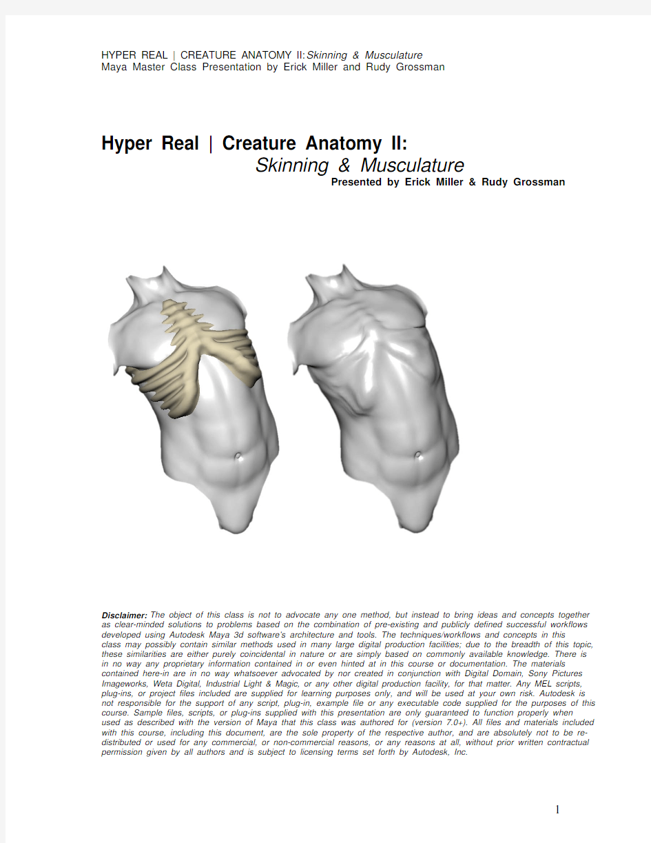

Hyper Real | Creature Anatomy II:
Skinning & Musculature
Presented by Erick Miller & Rudy Grossman
Disclaimer: The object of this class is not to advocate any one method, but instead to bring ideas and concepts together as clear-minded solutions to problems based on the combination of pre-existing and publicly defined successful workflows developed using Autodesk Maya 3d software’s architecture and tools. The techniques/workflows and concepts in this class may possibly contain similar methods used in many large digital production facilities; due to the breadth of this topic, these similarities are either purely coincidental in nature or are simply based on commonly available knowledge. There is in no way any proprietary information contained in or even hinted at in this course or documentation. The materials contained here-in are in no way whatsoever advocated by nor created in conjunction with Digital Domain, Sony Pictures Imageworks, Weta Digital, Industrial Light & Magic, or any other digital production facility, for that matter. Any MEL scripts, plug-ins, or project files included are supplied for learning purposes only, and will be used at your own risk. Autodesk is not responsible for the support of any script, plug-in, example file or any executable code supplied for the purposes of this course. Sample files, scripts, or plug-ins supplied with this presentation are only guaranteed to function properly when used as described with the version of Maya that this class was authored for (version 7.0+). All files and materials included with this course, including this document, are the sole property of the respective author, and are absolutely not to be re-distributed or used for any commercial, or non-commercial reasons, or any reasons at all, without prior written contractual permission given by all authors and is subject to licensing terms set forth by Autodesk, Inc.
Hyper Real | Creature Anatomy II
Skinning & Musculature
Introduction
This Master Class will discuss and demonstrate techniques used to create and manipulate the anatomy of a realistic cg creature. This is the second
class in a two part series, Hyper Real Anatomy I & II. The focus of this
second course will be to expand upon, elaborate, and continue to develop,
a thorough understanding of anatomy and how it relates to the features of
the deforming skin of a fantastic cg creature. Whether during the
modeling process, joint/skeletal placement or deformation process, a
strong foundation of anatomy combined with having great reference at
your fingertips is a truly priceless asset to have. This second course will
continue to reinforce this concept by outlining many of the various aspects in which knowledge and understanding of anatomy comes into play when
deforming a hyper realistic cg character or creature, and will explain each
concept and technique in the documentation, as well as through examples with supplied sample files as shown during the class.
Also, be sure to check out Paul Thuriot’s Hyper Real Body Rigging I and II classes and DVDs. The body rigging courses by Paul are excellent, and
many of the data and topics that are covered in this course pick up from
various topics in Paul’s excellent courses.
Topics covered in this course will be:
I. Muscle Rigging Solutions
o Home-brewed lofted muscles
o Using muscles as skin influence objects
II. Advanced Rigging & Skinning Solutions
o Wrist - radius/ulna setup that properly twists
o Clavicle/shoulder rigging & skinning
o Using HyperRealCorrectiveShape.mel & advanced skinning effects
III. Rigging Anatomical Transformation
o Blending techniques for blending the human to beast transition
o Advanced skinning techniques for transforming a human into a beast & using skeletal matrix data to avoid double transformations on the skin
IV. Skin/Flesh Simulation
o Overview of essential principals in cloth, skin, and flesh simulation.
o Simulating skin sliding over bones & muscle during monstrous transformation. o Adding volume preserving fatty flesh simulation onto an animated character.
I. Muscle Rigging Solutions
Creating simple anatomically based musculature for your cg creature does not have to be a complicated or difficult matter, in fact, the basic volumes
of anatomy (as described in the first course) can easily be replicated
within Maya using some nurbs curves and a loft node. This technique is
fairly popular, and works pretty well for creating basic forms of
musculature within a cg creature.
Home-brewed lofted muscles
Let’s start out by creating an object that could be used as a simple muscle influence object. Begin by creating a fresh new scene in Maya, and
performing the following steps.
1. Create a new scene – File->New Scene
2. Create a nurbs circle – Create->NURBS Primitives->Circle
3. Duplicate this circle, by hitting Ctrl+d, and translate it two units up in
the Y axis.
4. Duplicate the circle again, by hitting Ctrl+d one more time, and
translate it two more units up in Y again (so that the 3rd one is 4
units up in Y) as seen in the image below:
5. Next, shift select each of the circles in order, so that all three are
selected at once, selecting the first, second, and third in that order.
6. Next, under the modeling sub-set of menus, perform – Surfaces->Loft
7. You should now see a surface that has been created by performing the
loft command, this surface can be used as a basic muscle surface
8. Next, play with the cross sections. Try scaling the top and bottom
cross sections down to around .1, and then move them around.
9. Experiment and image where you could add muscle using this
technique into your character’s skin as a part of the crucial underlying anatomical structure. In the next section, as well as later in this course you will see a couple practical examples of using a surface such as this to help define the underlying structure. Open the file
simple_muscle.mb to see the Maya file used to create the above
example.
Using muscles as skin influence objects
The simple lofted muscle we created in the previous section can then be
used to deform skin very easily by attaching the geometry into a
skinCluster using the influence object option. This is a fairly common
technique, but, is definitely worth mentioning as it is very powerful and
definitely can help to achieve a realistic result when done with some
careful attention to anatomy.
The next example will be a more simple example of using a muscle as an influence object, but the same technique can easily be expanded upon to create more sophisticated skin deformation effects. Later in this course we will also show you how to perform flesh simulation on lofted muscle
surfaces, but for now, let’s take a look at the skin cluster influence object
example.
1. Start out by opening the file home_brew_muscles.mb. This example
was created quite simply by translating, scaling and parenting the
nurbs circles used to create the lofted muscle surface into position in a
rough approximation to a bicep muscle for the beast.
2. The beast was then skinned to the hierarchy of joints, and the weights
were painted in order to get decent looking deformations
3. Next, the lofted muscle surface (as created in the previous example)
was added as an influence object:
4. Select the smooth skinned mesh, and the influence muscle
5. Under the animation subset of menus, choose – Skin->Edit Smooth
Skin-> Add Influence (options box) – as seen in diagram below:
6. Be sure the Use Geometry option is checked on, and hit the Apply
button.
7. Now the lofted muscle surface influences the deformation of the skin
8. You can paint the weights of this muscle just as you could paint the
weights of the transform influence joints of the skin cluster.
II. Advanced Rigging & Skinning Solutions
Creating realistic deforming skin that is motivated by anatomy and
underlying structure does not always have to include the creation of actual muscles below the skin – in fact, often times it is simpler to take some
shortcuts and use joints to fake the appearance of underlying anatomy.
Of course only actual musculature results in certain realistic skin effects
that using muscle-like objects beneath the skin can give you, but, often
times - even on hero characters - this detail is not always needed. In
these cases, more straight forward – yet still advanced skinning
techniques can be used to create a very realistic and anatomically based
result.
Wrist - radius/ulna setup that properly twists (Wrist twist exercise) One of the hardest aspects of creating the deforming skin on a character
is giving it the ability to properly deform through the full range of realistic
motion that a real human-like character has.
For a moment, take a break from reading this document, and try rotating
your wrist around – just put your arm out in front of your body, and rotate
your palm facing up and twist your hand as far as it will comfortably go,
now, twist in the opposite direction. As you can see, the range of motion
of your wrist is almost a full 180 degrees.
Of course in cg animation, the whole purpose of creating something as a
cg creature is usually to make it do things that are not possible in reality,
so, this makes things like an animation friendly usable range of motion on the radius ulna fairly difficult to achieve without any collapsing or tearing to occur during deformations.
Here we will show you a quite simple way of building a wrist that properly
twists, without the need to build a full radius/ulna rig, you will get the visual result of properly twisting radius ulna skin deformations.
First, lets start by taking a look at the file arm_wrist_skinned.mb – examine how the joint structure was created, essentially we are distributing our wrist setup so that the skin can be weighted between 4 different joints, instead of simply 1 joint, this will allow us to have the skin twist all the way up the forearm more appropriately as the wrist twists.
Creation of this wrist twist skinned setup was fairly simple, here are the steps:
1. First, begin by creating a basic wrist, elbow, shoulder joint structure for
your character (by using, under the Animation subset of menus,
Skeleton->Joint Tool and using the defaults for the tool)
2. Next, duplicate the wrist joint, delete any duplicate children (i.e. any
duplicate hand that may be there now) so that just the new wrist joint is left – do this three times. Each time you duplicate the wrist and delete the new duplicate children so that only the wrist is left, move the new wrist upwards towards the elbow, as seen in the diagram above, so that each new duplicated joint moves closer to the elbow each time.
These new joints will function as extra skinning joints to distribute the wrist twist along.
3. Now, we want to extract the X rotation (this is the twist axis) from the
wrist, so that we can re-distribute it into the new joints that go along the forearm. Since Euler angles (this is the representation of rotation
channels in Maya) can have more than one solution during a rotation, we cannot reliably just directly connect the x channel of the rotation
from the wrist – instead, we will use a simple technique to extract this value – a weighted orient constraint.
4. Duplicate the wrist joint two more times, and delete any left over
children of the new duplicates so that only the wrist joint is left - but this time, do not move the new duplicates at all. Keep them directly
overlapping on top of the current wrist joint.
5. Now that you have duplicated the wrist joint twice, you will have two
new joints under the elbow, for clarity I will refer to the node names
included in the sample file: HRR_handJARt_2 and
HRR_handJARt_3.
6. Next, you will create a weighted orient constraint, but only on the x-
axis. The constraint will be used to extract the x axis rotation from the overall rotations of the wrist – but, instead of a single channel direct orient constraint, we will create a single channel constraint with two weighted inputs in the constraint in order avoid getting an incorrect
value when gimbal lock or Euler flipping occurs. This is the reason we have duplicated the wrist two times instead of just once.
7. Select HRR_handJARt_1 (the original wrist joint), then shift select the
new duplicate wrist joints, HRR_handJARt_3 and HRR_handJARt_2.
8. Next, go to the orient constraint options window, under the animation
menu sub-set, choose Constrain->Orient (options box).
9. Make sure that maintain offset is un-checked, and then check the “X”
checkbox. You should notice that when you check the “X” checkbox, the “Constrain Axes – All” is automatically turned off.
10. Next, with the 3 wrist joints all still selected from step 7, hit the “Apply”
button. You have now created a new orient constraint that is only
applied to the x rotation channel of a duplicate copy of the original wrist joint, and is equally weighted between the original wrist joint, and an additional duplicate wrist joint.
11. Now, HRR_handJARt_2 has the newly created constraint applied.
As you rotate the original wrist joint, you should notice that the
HRR_handJARt_2 joint only gets half of the original joint’s twist
orientation values. This is because it is weighted between the current wrist that moves around, as well as a wrist joint that is kept as a place holder of the original wrist location. This is what we want at this stage, and the reason is that by applying this weighted constraint, we help avoid flipping that could normally occur by simply doing an un-
weighted constraint.
12. Next, in order to get this new twist distributed along the skin of the
wrist, we will want to skin the joints that we created in step 2 of this
section. Each of these wrist joints should have smoothly distributed weights along the length of the wrist, as seen below.
13. Now, we will simply drive the x rotation of these evenly distributed
joints that are laid out along the wrist - as seen below.
14. Each distributed joint should get a smaller twist value as it gets closer
to the elbow, this way the twist will smoothly fall off and will not cause in-correctable collapsing to occur when the wrist is twisted. The
easiest way to distribute the twist quickly is to simply use an
expression.
15. To create the expression, load up the expression editor by going to
“Window->Animation Editors->Expression Editor”.
16. Type the following expression into the expression editor, and then hit
the “Create” button:
twist_1.rotateX = HRR_handJARt_2.rotateX * 2 * .9;
twist_2.rotateX = HRR_handJARt_2.rotateX * 2 * .5;
twist_3.rotateX = HRR_handJARt_2.rotateX * 2 * .2;
17. A quick glance at this expression shows how incredibly simple it is.
Each twist joint is assigned a value that is equal to the constrained
wrist joint’s x channel, multiplied by two since the value is halved
because of the fact that the constraint is weighted between the current value as well as the original value. This causes it to be half of the
actual value – so, we multiply it by two in order to get a value that
represents the full twist amount. A cheat, for sure, but it works ?
18. Next, each of the doubled twist values are multiplied by a float value
between 0 and 1. These multiplier values will give you the ability to control how much of the twist from the wrist is applied across the extra weighted joints. The values used here (.2, .5, .9) may or may not work best for different examples – experiment with different values, for
example, .3, .6 and .9 may work well also. You could also create even more joints to distribute the twist along, and use a finer set of multiplier values – for example if you had 6 wrist twist joints, you could try using
.167, .333, .5, .667, .833, and 1. Just remember that you want a
higher multiplier value as the joints are closer to the wrist, and a lower
value as the joints are closer to the elbow.
19. Have fun & experiment distributing wrist twist using the simple orient
constraint technique!
Clavicle/Scapula/Shoulder rigging & skinning
The shoulder area of a realistic character is a difficult area to master, due to the obviously in-correct application of a single shoulder joint via direct
smooth skinning. Since the shoulder in a realistic creature is made up of many complex connections of bones, tendons, sinew, muscle and floating joints, this area of a creature can be deceptively difficult to skin with the
ability to perform a realistic range of motion. The clavicle, scapula, and
shoulder (deltoid) all connect together to form a unique intersection with
the pectorals, the biceps and triceps, the trapezius, latissimus dorsi, as
well as the ribcage and serratus areas. There really isn’t a more crucial
or critical area in the body when it comes to complexity of anatomical
deformations – so we will focus on this part of the body next.
We can start by opening and examining a completed setup file that has a
skinned shoulder rig: arm_shoulder_skinned.mb
1. Let’s begin by examining the general joint layout used. Since it is
difficult to describe exactly where each joint should be placed, examine
the following image to get a better idea of joint placement prior to
starting this exercise.
2. The first thing to recognize for this tutorial is the series of joints used to
deform the overall mass of the shoulder – this is the long series of
joints that extends into the upper arm of the character. Start by
creating this joint chain. Begin drawing joints (using the joint tool)
starting somewhere close to just below the base of the neck,
somewhat parallel with the opening of the shoulder into the body.
Draw somewhere between 10 to 15 joints, extending the joints into the center of the upper arm, and ending the joint chain just before the
elbow as seen in the sample file and in the image above labeled
“Shoulder Joints (spline ik)”.
3. As you may be able to guess, this new joint chain will be used to skin a
major portion of meat on the shoulder, and a spline ik will be applied in order to connect this joint structure with the main shoulder joint that gets animated. This will be done by skinning the spline ik curve, and then extracting the twist using the weighted orient constraint technique as shown in the wrist twist exercise.
4. So, now lets add some spline ik to this new set of shoulder joints by
choosing “Skeleton->Ik Spline Handle Tool” options box. Reset all the settings to default in the tool settings window, and then un-check “auto simplify curve” – next, create an ik spline by selecting the first and last joint in the shoulder chain.
5. Now, a new nurbs curve has been created, and the shoulder joint
chain is being controlled by this curve through the use of the spline ik
solver. Next, select the HRR_clavJARt_3 as well as the
HRR_armJARt_1 joint, then shift select the newly created nurbs curve,
and skin the curve (Skin->Bind Skin->Smooth Bind) so that the
shoulder and clavicle joints control the spline ik nurbs curve.
6. The only thing missing now for the shoulder joints is parenting the joint
chain into the hierarchy of the spine, as well as putting the twist from
the shoulder into the spline ik shoulder rig.
7. Use the weighted orient constraint technique to extract the twist value
(exactly as shown in the wrist twist exercise). Since the technique for
extracting twist was already covered in detail, please refer to the wrist
twist exercise section in this document for detailed information on how
to extract the twist value.
8. Once you have the twist joint created, you will want to drive the twist
attribute of the spline ik handle, instead of the x rotation of each
individual joint. The spline ik automatically distributes twist along the
length of it’s chain, and this works quite well, especially for the use we
are making of it here in the shoulder to arm region. We are going to
only use 75% of the full twist of the shoulder in order to drive the spline
ik twist. This gives us a more natural looking deformation and creates
less collapsing and a bit extra distribution of twist along the shoulder
and arm regions.
9. Plug the following into a new expression in the expression editor in
order to set up the driving of the twist:
ikHandle2.twist = (HRR_armJARt_2.rotateX * -2) *.75 ;
Note: The node HRR_armJARt_2is the joint with the weighted constraint applied in order to extract the twist value (once again, check out the wrist twist tutorial). Also note that we are multiplying here by negative two instead of positive two simply because the x twist orientation direction is flipped on the joint chain being used for the shoulders in this particular scene.
10. Now that these shoulder joints are added, keep in mind that careful
weight painting will have to take place in order to smoothly spread the
weights out across the skinning on the shoulder so that even and clean
deformations take place across the arm and the shoulder. Check out
the sample scene for a rough example.
11. Next, we will want to add a clavicle and scapula joint in order to
complete our shoulder skinning rig. These setups are a bit more
simple, but none-the-less important aspects of the shoulder that can
not be ignored.
Above, the scapula is on the far left side, and the clavicle is on the far right. Notice the shoulder joint chain we just finished making is running directly down the middle.
12. Using the sample arm_shoulder_skinned.mb file as a guide, create a
clavicle joint and a scapula joint (as seen in the diagram above). For
the clavicle joint you can just create it using the joint tool, but – for the
scapula, you should duplicate the driver joint, HRR_clavJARt_3 so
that it will have the exact same rotation orientation and order as it’s
driver.
13. Now, parent the clavicle joint under the closest spine joint, in our case
this is joint HRR_spineJD_1
14. Next, parent the scapula joint below the joint be driven by the
animation controls for the clavicle/scapula motion – in our case this
will be the joint named HRR_clavJARt_3
15. Now, to rig the motion of the scapula, simply create a “y” channel
weighted constraint and drive the y rotation of the scapula – but, the
trick here is to again use an expression, but this time multiply the
scapula’s y rotation by negative one, so that as the arm moves up, the
scapula’s y rotations counter animates it downward. This can be
create via a simple expression:
HRR_clavJARt_5.rotateY = HRR_clavJARt_7.rotateY * -2 ;
Note that the joint HRR_clavJARt_7is a weighted constraint, as covered in the wrist twist example, thus the value is -2 instead of -1. Take careful note that we are using a negative value here for a different reason then why -2 was used for the shoulder spline ik rigging. The reason we are using negative two in this example is so that the scapula counter
animates down as the arm moves up. In the previous example we
used negative two simply because the orientation of our joints vs. our spline ik twist was going in the opposite direction so we had to flip the value.
16. Next, rigging the clavicle is fairly simple. Create an Ik handle, using
the “Skeleton->Ik Handle Tool (options box)” and be sure to choose “ikRPsolver” so that a proper pole vector can be created to stabilize any flipping by constraining the twist.
17. Draw a single joint ik handle from the start joint of the clavicle (near the
center v of the chest) to the end joint that attaches at the crest point of the shoulder.
18. Now, create a locator, and parent it below the closest spine joint, in our
case it would be the HRR_spineJD_1 joint. Next, move the locator into a position somewhere in the center of the neck, directly above the clavicle (see diagram below).
19. Next, select the locator and shift select the newly created ik handle,
and create a pole vector constraint by choosing “Constrain->Pole
Vector”.
20. Finally, parent the clavicle’s ik handle under the main shoulder joint, in
this scene it is the HRR_armJARt_1 joint. Doing this will cause the clavicle to aim towards the shoulder and appear to be an additional bone that is attached and deform the skin in an anatomically expected manner.
21. At this point, you will now want to smooth skin these new joints, and
carefully paint the weights so that they are smoothly distributed across the geometry and there is no tearing or collapsing. This is a time
consuming part to get perfect, and the time should be spent at the
phase so that the skin looks as good as you can possibly make it by simply skinning it to the bones – this way when you need to make
additional changes later, you will have the best possible starting place to add more advanced deformation effects, such as corrective
blendshapes, sculpt deformers, or even skin simulation techniques.
You always wan to be sure that your base skinning is the best it could
possibly be, so being very attentive to the weight painting at this stage
is a crucial process.
By now you should have a finished Clavicle/Scapula/Shoulder deformation rig. Once again, check out the scene arm_shoulder_skinned.mb to see a completed example – a bit more time could have been taken on the weight painting portion in this scene, but over all it is a pretty good example.
Keep in mind that the technique of creating a spline ik joint chain and skinning to the joint structure below can be used on a large number of different areas in the body, and is not restricted to working well for only the shoulders. This technique would work very well for pectoral muscles as well as for the upper legs to hips attachment and many other areas in the body as well – it’s great for having anatomically based bending, but being able to apply the twisting across the skin of the model, and it’s all using simple techniques and tools already built into Maya’s skinning technology in order to do so. Experiment and have fun!
Using Hyper Real Corrective Shape for Advanced Skinning Effects The hyper real corrective shape script is a simple but powerful technique
for applying corrective blendshapes onto your deforming skin’s mesh, and being able to drive the shapes on using a single joint as the driver. This is
a really easy and fast way to start getting even more anatomically
motivated details to start appearing in the deforming skin, since as an
artist you have the ability to sculpt the poses into the shape that they
should look along the way.
To learn how to use the hyperRealCorrectiveShape script is simple – First, open up the example scene hyperreal_corrective_shape_example.mb
scene and play through the time line. Notice that as the elbow bends, the bicep bulges a bit and the forearm keeps it’s form fairly well. This is
because, in conjunction with some skinning techniques shown in the first
course, this file has a corrective shape that is being driven on as the elbow begins to bend.
It is important to note that this technique is not pose space deformations,
nor is it a substitute for such a system – instead, it is rather a simple
technique for applying actual blendshapes (parallel blend shapes) onto a
smooth skinned model – but, one of the coolest thing about this script is
that it requires no plugins, no custom nodes, and no complicated
calculations or algorithms - it simply uses Maya’s skin cluster, blend
shape, and a fairly straight forward expression with set driven keys to do
it’s magic.
To start creating your own hyper real corrective shape inside your scene, first source the hyperRealCorrectiveShape.mel MEL script by opening the script editor window, doing “File->Source Script” and choosing the hyperRealCorrectiveShape.mel supplied with this course. Next, follow these steps:
1. In the script editor window, or the MEL command line, run the following
command after you have sourced the hyperRealCorrectiveShape.mel script:
hyperRealCorrectiveShapeWin();
2. Running this command will open up a simple window that looks like
this:
3. Open a character rig, and pose a single joint into a position that you
would like to correct the deformations. Here is an example below of an fairly extreme twisted shoulder deformation that we can correct:
基于Maya的人物角色行走运动的设计
计算机与现代化 2010年第3期 J I S UANJ I Y U X I A NDA I HUA 总第175期 文章编号:100622475(2010)0320023203 收稿日期:2009211201 作者简介:邱亚萍(19842),女,江西临川人,集美大学诚毅学院助教,硕士,研究方向:动画原创设计及研究。 基于Maya 的人物角色行走运动的设计 邱亚萍 (集美大学诚毅学院,福建厦门360121) 摘要:阐述在M aya 软件中制作人物角色行走的流程以及一些相关注意事项。通过分析人体行走过程的重要特征,详细论述人物角色行走动画的制作过程,探讨M aya 技术在人物角色行走动画中的应用技巧。关键词:M aya;角色行走;动画制作 中图分类号:TP317.4 文献标识码:A do i:10.3969/j .issn .100622475.2010.03.007 D esi gn of CharactersW a lk i n g M ovem en t Ba sed on M aya Technology Q I U Ya 2p ing (Chengyi College,J i m ei University,Xia men 360121,China ) Abstract:This paper expatiates the p r ocess of making characters walking,as well as s ome related considerati ons with M aya s oft 2ware .Based on analysis of characteristics of hu man walking,this paper circu m stantiates such ani m ati on p r oducti on p r ocesses,and discusses app licati on skills adop tingMaya technique in such p r ocess .Key words:Maya;characters walking;ani m ati on making 0 引 言 Maya 是美国Aut odesk 公司出品的世界顶级的动 画软件,广泛用于影视制作、游戏开发、角色动画、网页设计和广告创意等领域,是有史以来最大的商业3D 图形应用软件。Maya 在复杂性和功能性上都远 超其他3D 动画软件,其强大的3D 建模、动画、纹理、灯光和渲染以及动力学模块吸引了无数计算机动画人员深入探索。 三维角色动画是计算机动画技术中最具挑战性的课题之一,主要涉及到建模、运动控制和绘制三个过程,其中运动控制难度最大。首先,人体的运动自由度极大;其次,人体的任何动作都是许多因素协同作用所致;第三,每个角色都有自己的个性,如何体现角色个性是关键所在;第四,由于人类行走是最常见的运动,因此角色运动中任何细微的不协调都很容易被观者所察觉。 本文针对目前仿真人体直立行走过程中存在的 缺陷(如动作不自然问题、姿态转变存在突变现象等),分析在Maya 中人体的运动模型及直立行走的控制方法,并对人体运动控制过程进行探讨,有效提高人体运动的自然性和真实感。 1 人体行走过程分析 目前,国外对三维人物角色运动控制的研究主要采用三种方式:(1)关键帧方法;(2)运动捕捉技术;(3)基于仿真的运动控制方法。本文对人物角色运 动控制的研究是基于仿真的,着重于人物角色步行运动控制方法的研究。 为在动画场景或虚拟环境中生成人物角色的动态步行运动,必须进行如下工作:把步行运动过程简化为一个固定周期的重复运动,综合设计这一个固定周期内人物角色的步态轨迹;运用某种控制方法实现周期内人物角色对期望步态轨迹的跟踪控制;分析相邻运动周期之间的切换条件,控制人物角色实现连续稳定的周期性步行运动。
maya模型教程:真实角色模型的创建
第6章真实角色模型的创建 本章讲述真实人物角色的制作流程。研究人类头部布线的目的是为了制作表情动画,因为人物的各种内心活动主要通过面部的表情变化反映出来。由于建设模型主要锻炼造型能力,故而对形体和结构的理解尤为重要。 本章主要内容: ●真实角色头部的制作 ●真实角色身体的制作 ●布线的方式一定要与肌肉运动的方向相符。 ●关键部位需要足够的线,有足够的控制点,表情才能做到位。 6.1.真实角色头部的制作 本节将参考图6-1中人类头部肌肉解析图进行头部建模的教学。 图6-1人类头部肌肉解析图 【例6-1】制作人类的头部 1)首先通过Create >Polygon Primitives >Cube命令建立一个如图6-2所示的多边 形立方体,作为真实人物角色头部的框架。
图6-2创建立方体 2)执行Mesh >Smooth命令,把立方体平滑一级,之后删除如图6-3所示所得物体 的一半的面。 图6-3平滑立方体图6-4调整头部线段 3)然后调整头部的形状,并通过Edit Mesh >Cut Faces Tool剪切面工具在人头的侧 面纵切一条线段进行调节,如图6-4所示。 4)同样操作,在人头中线的上、下位置各切出图6-5中的两条线作为眼睛的定位。 图6-5眼睛定位线的创建图6-6定位线的制作
5)接下来,在鼻梁的位置处纵切出一圈线,还有在眼睛的中心位置再切出一圈线,如 图6-6所示。 6)现在,调整整个头部的形状,如图6-7所示。 ※注意:要把头部的整个形状先调圆,再继续制作。 图6-7调圆头部 7)然后,在头部的侧面位置使用Edit Mesh >Insert Edge Loop Tool插入环线工具添 加两条环形线段,如图6-8所示。 图6-8添加两条头部侧面的线段图6-9画出眼睛的轮廓 8)在面部的正面找到眼睛的位置,画出它的基本轮廓,如图6-9所示。 9)在眼睛与眼眶之间添加线段,参考图6-1中眼睛的比例,调整模型上眼部的形状, 如图6-10所示。 图6-10在眼周围加线段图6-11添加约束眼角的线段
maya动画教程:动画基础概论
第1章动画基础概论 动画(Animation)一词是由拉丁语的动词animate(赋予生命)演变而来。1980年,国际动画组织(ASIFA)在南斯拉夫的Zagreb(今天的克罗地亚首都)召开动画会议,会上对动画(Animation)一词的定义是这样的:动画艺术是指除使用真实之人或事物造成动作的方法之外,使用各种技术所创作出的活动影像,亦即是以人工方式所创造的动态影像。 那么,什么是动画片?在美国,动画和卡通两个词汇曾经没有任何区别。而在日本,Mange就是漫画,Anime就是动画。现代动画片的概念,是从其技术实现的角度来定义的。它是采用“逐格摄影”的方法将影像拍摄在胶片上,然后以每秒钟24格的速度,在银幕上逐一放映的动态影像。由于所拍摄的影像互相之间只有细微的变化,因而形成了系列动态的影像感觉。 本章的主要内容是介绍动画的历史和发展。在学习动画之前,应当先了解动画这个艺术表现形式,动画是影视艺术的一个分支,它的基础源于绘画,将一幅幅连续的图画顺序播放,就得到了一个活动的影像,这就是动画最基本的原理。本章将从动画片的分类、三维动画的技术分类、世界动画的发展史以及中国动画的发展史这四个方面介绍动画的基础概念。 本章主要内容: ●动画片的分类 ●三维动画技术类型 ●世界动画发展史 ●中国动画发展史 动画的起源和发展以及三维动画的技术分类。 1.1.动画片的分类 动画片的分类其实有很多种,主流的分类方式大致会把动画分成以下三种: ●手绘动画(Cel Animation) ●电脑制作动画(computer animation) ●定格动画(stop-motion animation) 1.手绘动画
MAYA人头建模终极秘笈
转一篇MAYA人头建模教程。教程可谓经典到掉渣。深入的从MAYA人头建模各个层面详尽的介绍了人头建模的方法和所有应当注意的细节。转发飞特。和飞特学习MAYA的朋友们一起学习。 一、简介 建立可信的人脸,是每一个三维艺术家的最终目标之一。但是要获得真实和自然的作品需要我们在每一步都做到最好,包括资料的收集、模型的规划、纹理的绘制和最后的渲染等等。在这篇文章中我讲解研究建模的过程,谈论如何使用Maya或其它工具怎么一步步的完成模型。如:工作的流程、建模的不同方法、拓补的结构、常见的错误等等。 二、开始建模前的准备 在进入建模之前,我研究了怎样获得好的参考图片或是绘制的概念图。这些东西对我们后期的建模有非常重要的作用,参考图片和概念图的质量将直接影响到我的模型的准确性。如果我们在这个过程中犯了错误,那将在建模的时候遇到很多问题,可能我们模型会在匹配正面的图片,但侧面确看起来不是那么回事。这些错误将耗费我们大量的时间去修改。 如果我们要使用真人的照片来做参考,那么照片的角度是非常重要的,否则我们的模型将是错误的,而我们会不得不花费大量的时间来调整。另外我们也要考虑到照相机的焦距,焦距越长越接近我们参考模型用的视角。然而从理论上说因为视角的变化我们得到的照片总是和真人有区别的,我们参考图片做册模型会比真人略胖,当然这个问题可以通过后期的修改来解决。另外我们还需要考虑图片上灯光,太亮或太暗的光线的图片会隐藏很多细节,所以我们不能使用。 比较差的参考图片,尽量不要使用下面这样的图片 图片1 比较好的参考图片
图片2 在Maya里建立参考图片因为视角的差异,我们无法直接从照相机获得直接用于Maya的参考图片,我们应该在Photoshop中进一步修正我们需要的图片。 下面的正侧面细节不能匹配 我们通过修改让图片匹配
maya模型教程:通角色模型的创建
第5章卡通角色模型的创建 本章将通过实例讲述卡通角色的制作全流程。通过制作角色的头部、衣服和鞋子等来掌握卡通角色制作要领与规范。 卡通角色的制作要求严格对照参考图片,制作完成后的模型渲染图片保存成JPG格式与角色设计图一同导入到Photoshop软件中,作比例与造型对比。卡通角色的制作分步明确,每一个步骤都有其特殊的意义。通过卡通模型制作了解人物基本造型与布线的方法,为真实人物的制作打下良好的基础。 本章主要内容: ●卡通角色三视图的剪切和导入 ●卡通角色头部的制作 ●卡通角色身体的制作 ●对卡通形体整体结构的把握 ●对结构线段的加深理解 ●对造型能力的加强练习 5.1.卡通角色三视图的剪切及导入 本节将通过一个小例子教给大家将设计稿导入Maya软件的具体操作过程,这是做模型,特别是角色模型时必须牢牢记清的环节,请随本书认真学习。 【例5-1】卡通角色三视图的导入操作 制作卡通模型之前,要有参考图片。那么本节首先介绍如何正确导入制作卡通角色必备的参考图片。 5.1.1.卡通参考图片的剪切 拿到卡通角色设计稿后,一般情况下是用二维软件绘画出的有正面、侧面、和背面的JPG格式的图片,在此统称为卡通角色三视图。
1)在Photoshop里打开光盘中的图片文件images\design\chapter5\boy.tif,现在进行图 片的裁剪,以准备Maya软件中需用到的标准且合理的参考图,如图5-1所示。 图5-1卡通角色三视图 2)用Photoshop软件将选好的卡通角色图片按正、侧、背视图切开,侧视图和背视图 参照已经切好的正视图协调比例,如图5-2所示。 ※注意:有时正、侧视图无法完全对齐,我们要以正视图为标准,侧视和背视图作为正视图的参考。调整后,按正、侧、背三视图分开保存,保存为JPG格式即可。
maya角色绑定教程
● 武汉市洪山区兆富国际大厦2603A ,430074 ●+86(027)87870255 87877031 ● 2603A, Block One, Forture International Building, wuhan ,China 430074 ●Web:https://www.360docs.net/doc/861893556.html, maya 角色绑定教程 (一, 创建骨骼部分) 创建骨骼命令在animation 的面板当中,skeleton>joint tool,我们在创建骨骼之前,先分析下骨骼的属性。打开joint tool 后面的方块 进入骨骼的属性当中,骨骼是有方向性的, 和 两个方向是常用的。以xyz 方式为例,x 轴指向关节延伸的方向,y 和z 其实没什么 意义;同理yzx 就是y 轴指向关节延伸的方向。原则上这个选项可以随便选,但最好统一一下,一般对齐关节都选xyz 方式就可以了。而None 则是和世界坐标轴一致的。 在单独调整骨骼时,要始终保持骨骼的旋转属性为0。 我们在创建骨骼时,最好保证骨骼在模型的中间,这样在后面分配权重的时候,就能减轻我们的工作量。 在创建骨骼之前,先创建一个图层,命名为boy_mo ,将模型添加到图层当中,锁定线框显示。 步骤1: 为脚部创建骨骼,将maya 的操作视图转到(side )侧视图,在侧视图中,我们从大腿跟部向脚踝方向创建出腿部骨骼。A_leg_L_bn ,A_knee_L_bn ,A_ankle_L_bn 。骨骼方向选择xyz 方向。 我们创建出来的骨骼就会在网格上产生,将它移动到然后在工具栏中,进入骨骼的子级别 ,将 激活。统一骨骼的旋转方向: 选择最后一节骨骼的方向坐标轴,skeleton>orient tool ,点击后面的小方框,在属性当中修改orientation 的属性为none ,应用。让他和其他骨骼方向统一。如图1-1所示。 旋转大腿根部的骨骼,统一方向后要记得回到物体级别。 如图所示。 步骤2: 我们在前视图中可以看出,我们的骨骼不能很好的和模型对位,将骨骼自身成组,选择组,按insert 键,v 键点吸附到骨骼链的根关节上,完成后再次按insert 键,切换到正常模式。
掌握maya动画的七个技巧
本教程将讲解有关动画操作的7个技巧,分别是IK与FK、IK与FK的转换、表达式实现动画效果、父子关系与父子约束、权重绘制技巧、关键帧和制作循环动画。 技巧一:IK与FK IK与FK主要应用在骨骼绑定中,IK即反向动力学,是指根据末端关节的位置移动来控制其父关节的旋转操作,FK即正向动力学,是指根据父关节的旋转来控制其子关节的位置,下面通过一个小实例来具体讲解IK与FK的区别。 step 01.单击Animation(动画)工具架上的(骨骼工具)按钮,在场景中创建下图(左)所示的两个腿部骨骼。 step 02.单击(IK手柄)按钮,在右侧骨骼的“Joint1”和“Joint3”关节上分别单击鼠标,为其创建一个IK,如下图(中)所示。当前左侧骨骼为FK,右侧为IK。 step 03 要想为左侧的骨骼设置屈腿动作,需要执行以下两个步骤:使用旋转工具对“Joint01”关节做如下图(右)所示的旋转。 使用旋转工具对“Joint02”关节做如下图(左)所示的旋转。 step 04. 要想为右侧的骨骼设置屈伸腿动作,只需使用移动工具移动右侧骨骼上的IK手柄,整个腿部会随之移动,做屈腿伸腿运动,如下图(右)所示。
由此可见,当前使用IK来调节屈腿伸腿的动画比使用FK要容易,但是就灵活性来说,IK却不如FK,使用IK只能调节出常规的动作,它有一定的限制,而使用FK则可调节出任意动作,如下图所示,这是IK做不到的,因此IK与FK各有利弊,在制作具体的项目时,要依据所创建的模型和要调节的动作来选择使用IK还是使用FK。 (提示:由于IK和FK的作用是互补的,因此在绑定角色的骨骼时,通常会在腿部、身体和胳膊等部位分别创建IK和FK,以方便根据不同的情况做出不同的选择。) 双击Animation(动画)工具架上的(IK手柄)按钮,会弹出IK手柄工具的参数,如下图(左)所示,在Current solver(当前结算器)中有两个选项,分别是ikSCsolver和ikRPsolver,其中ikSCsolver是没有极向量的,多用于控制骨骼的长度,ikRPsolver是有极向量并可对其进行调节的,多用于胳膊、膝盖等部位,如下图(右)所示。 技巧二:IK与FK的切换 本小节将通过一个小实例来讲解切换IK和FK的方法。 step 01.单击Animation(动画)工具架上的(骨骼工具)按钮,在场景中创建下图(左)所示的骨骼。 step 02.单击(IK手柄)按钮,然后在“Joint1”和“Joint3”关节上分别单击鼠标,为其创建一个IK手柄,如下图(中)所示。 step 03.打开通道盒,此时Ik Blend(IK弯曲)的值为1,选择并移动IK手柄,骨骼会随之移动,如下图(右)所示,这说明此时IK是打开状态。
MAYA坦克建模
MAYA tank modeling 这篇教程教飞特的朋友们介绍MAYA坦克建模的过程和具体的建模方法。教程很经典。写的也很详细。这里先感谢作者给我们制作这么好的MAYA建模教程。转发到飞特,也希望飞特的朋友们喜欢这篇教程。先看看最终的效果图: 目录 1.制作坦克模型的前期工作 2.模型的基础搭建 3.倒角的工具的应用 4.分析坦克上的一些部件的制作过程及其工具的应用 5.履带插件的运用方法 第一章制作坦克模型的前期工作 一.对于制作一个好的模型来说前期工作至为重要,所及充分的资料可以让你在制作中省去很多不必要的麻烦提高制作进度及其真实度。所以我在制作这个辆M1A2的时候就收集了大量的资料图片和散视图作为我所要制作的这两坦克的参考。 在补充一句如果你的经济条件允许的话最好买一个模型玩具当作参考这样效果会更加。
二.三视图的制作及其导入 1.首先在PS里打开我们所需要的三视图
这个步骤我想大家应该没什么问题。很简单运用剪切工具在配合ctrl+T来制作出右边的那三张不同角度的视图。 为了使视图的比例完全一直你可以把这三张截玩的视图托到一起运用降低透明度和变形命令(CTRL+T)来调整他们的大小。 调整完成后在分别保存一下为我们下一步工作做准备。 2.视图制作完毕现在我们打开MAYA。然后在front视图中的view/image plane/Imoport Image…点击一下然后导入相应的视图。 3.在执行一次view/image plane/你会发现Imoport Image…下面多出了个Image Plane Attributes点击一下他会出现image Plange点击他就可以进入你所在视图的编辑菜单。
怎样用Maya快速制作人物模型
1、MAYA制作CS人物模型首先用多边形制作出人物模型。注意的是游戏引擎的极限,这里做的是cs1.5和1.6的游戏模型,引擎限制人物的三角面是1000左右,官方的都是700个面。在用maya或max建模时,要保持四边形在500以下才能保持三角面在1000以下,超过hl引擎极限就无法在游戏里运行。 2、接下来选中模型,执行命令editpolygonsnormalssoft/harden这里选用soft180来软化模型的法线。这样后模型就给法线圆滑了。
3、展开uv时不要忘记分割模型的uv,这样才可以更好的进行uv操作。这里分割了10个部分的uv。如果模型的左右对称,除了头以外。身体的uv只要展开一半就行了。然后镜像模型可以得到另一半的uv。 4、接下来展开模型的uv纹理坐标。建立一个材质球,就lambert就可以了。用checker2d纹理来对位。展开模型的uv如图就行了。
5、展开uv后,我们的10个部分都可以在maya的uv编辑器里查看。注意把所有的uv要放在纹理坐标的第一像限里还可以导出uv,其他三人像限坐标和第一个像限是一样的。 6、现在打开ps-cs来画贴图,先把uv导过来,然后在它上面对位画贴图,一层一层的画。
7、贴图后,不显示那些不需要的图层,另存文件为xx.bmp文件,大小是512*512,深度为8位,一定不要错,不要以后hl引擎是不识贴图文件的。记得保存原psd文件,方便以后个性修改。 8、观察模型的贴图,修改一些不合理的地方,包括比例、结构等。由于是1000
面以下的底模,所有的关键都在贴图上。 9、修改好后,我们不一定要在maya里渲染,因为现在做的是游戏模型,是要在游戏引擎里及时渲染的。下面我们将进入模型的骨骼、蒙皮、权重的工作。cs 模型的骨骼是有它一定的要求的。 10、接下来的任务我们要在milkshape3d1.7.0里完成。这是一个游戏制作有转
Maya人物跑步动画
精品文档 。 1欢迎下载 人物跑步动画 【教学目的】 介绍人物跑步的基本运动规律, 【学习重点】 跑步的基本运动规律 1 跑步的基本原理 1.1 跑步与走路的区别 前面介绍了走路的动画的制作,跑步的制作方式和走路的方式是一样的,但是我们怎样 来区别这两个动作的不同呢!虽然跑步在日常生活中经常看见,但是我们可能从来没有仔细的分析每一个动作。现在我们再来简单的说一下走路的动作。 首先,走路只有一只脚是离开地面的,而且走路有两只脚同时接触地面的一段时间,虽 然很短。但是跑步就不一样,下面我们来看一下区别。 跑步中的某些点,比如说位置 1,2或者是3,两只脚都离开了地面。 做一个快速行走——如果总是一只脚着地,我们就跑不起来——我们的得到是一个非常 快速的步行。(每秒钟4步。)(图) 但是如果仅仅使6号画面离开地面,我们就可以得到一个跑步的动作。(图)我们不用那 样做,但是那是区别步行和跑步的一个特征。
这是一个更生动一些的跑步的动作,几乎和上面的那个图片是一样的,只是胳膊和腿部摆动幅度更大一些,还有一帧两只脚同时离开地面。虽然只有这一点区别,但是我们看起来比上面的图片,更像跑步很多。 我们可以使用同样的图画,把最低点放在3号位置,把最高点点放在紧挨着它的4号位置(图),现在再比较一下上面的那张图,是不是更生动了。 这是一个比较夸张,卡通成分更多一些的动作,一个卡通的跑步动作——但是有两个位置(5.6)两只脚都离开了地面,这个跑步的动作就激烈很多然后我们就要加上强烈的胳膊摆动。这样我们得到一个比较激烈的跑步动画。(图) 通过这些我们知道了跑步和走路的区别,这样我们在做起动画来的时候就会方便得多,该在什么地方,把pose调到什么样,我们做到心中有数,不会被别人说,你做的这个好
Maya角色动画导入VUE技术贴(原创)
Maya角色动画导入VUE技术贴(原创) 吖辉 用过VUE的都会知道Poser角色动画可以导入Vue,但是同样有各种限制存在。而且相对冷门的Poser用户也不多,其实Maya的角色动画也可以导入Vue。 在去年我就测试得出Maya的角色动画可以通过点烘焙的方式进入Vue。PJ一直让我写个教程,但是一直没有时间,今天把这个步骤大概讲一下,非常简单。希望能帮到有需要的朋友。 首先我得感谢PJ千辛万苦为我找到这个叫PointOven_1.5142_Maya的插件,插件的安装方法很简单,我截两张图讲下。 解压后会出来两个文件夹: 2013_64Bit文件夹内有上图6个mll文件,把这6个文件放到C:\Program Files\Autodesk\Maya2013\bin\plug-ins 里面。
Mel文件夹内有以上4个文件,将他们放入 C:\ProgramFiles\Autodesk\Maya2013\resources\l10n\zh_CN\scripts 后面就不用讲了,打开maya插件管理器给这几个勾上勾就可以了,在maya 菜单栏上会出现PointOven菜单。 然后准备工作就做好了,在这里我使用在CG模型网上下载的魔戒咕噜的带动画绑定的角色做演示。
1.首先:选择角色模型,然后执行 2.弹出对话框,勾选MDD栏下Export MDD file for Selected Meshes 然后设置MDD文件保存位置。 3.选择Object栏,勾选Export Meshes,选择LWO格式,设置LWO保存位置
4.然后点击,开始烘焙。 5.然后选择场景,把所有场景执行冻结变换,中心坐标对其,清除历史记录。 6.选择场景,输出为Obj格式。 7.打开VUE,执行Import object,找到刚才输出的LWO模型,导入VUE 8.导入的时候会弹出下图对话框,勾选Maintain vertex order (MDD),点击OK。 9.导入场景OBJ文件,因为刚才在maya里已经执行过冻结变换等,所以文件很干净,与LWO角色模型的位置直接匹配。
maya动画教程:角色基本行走动画
第6章角色基本行走动画 本章将教授制作角色的基本行走动画。角色行走动画可以通过关键帧动画来实现,在制作之前需要分析行走动作,将动作过程中的关键动作提取并在Maya里设置关键帧,通过不同关键帧的过渡来实现行走动画。 本章主要内容: ●行走动作的分析 ●基本行走的循环动画的制作 ●基本行走的动作分析 ●根据动作分析制作关键帧动画 ●修改并调整动画曲线 6.1.行走动作的分析 在一部动画片中,角色行走的动画十分常见,所以掌握角色行走的基本动作规律是非常重要的,也是每个动画师必须掌握的基本技能之一。 所谓基本行走动画,指的是角色在行走过程中不附带任何的感情色彩以及情绪,例如角色负伤行走、背着重物行走、角色心情低落地行走等都属于带有感情色彩的行走。制作行走动画的方法有很多种,本章会为读者提供其中的一种制作方法。 制作角色循环行走的具体步骤如下: 1)步伐的制作; 2)身体重心的制作(身体上下重心以及左右重心转移的交换); 3)胯部旋转的制作(胯部左右旋转以及侧旋); 4)胯部以上至胸部旋转的制作(身体的前后旋转、左右旋转以及侧旋); 5)手臂的弧线摆动以及小臂、手腕跟随运动的制作; 6)头部的制作; 7)细节的调整(脚部以及手指的细节和动画曲线的调整)。 在开始制作之前,首先要对角色行走时身体各个部位的运动规律进行系统地分析。
6.1.1.步伐分析 当一个角色向前行走时,两只脚会以前后交错的方式进行规律性的运动,这样才会使身体保持前后的平衡。与其说是行走,不如说是一连串防止跌倒的控制过程。 行走有不同的节奏,例如轻快的竞走、缓慢沉重的走、大步流星的走,通过节奏上的变化,会产生不同的效果。一个不附带任何情绪的完整的行走一般需要25帧时间,也就是1秒钟。第1帧~第13帧为一步,第13帧~第25帧为另一步。图6-1是角色其中一只脚的运动过程。 图6-1基本行走中脚的运动 6.1.2.身体重心分析 在行走时,由于下肢的运动会导致身体上下的重心产生忽高忽低的起伏变化,有了这种变化,才会使角色产生重量感。在制作过程中,要根据角色的性格和身材来调整上下起伏的幅度。 当角色迈出一步的时候,会有5个关键帧来控制身体上下重心的起伏。它们分别在第1、4、7、10、13帧上。迈出另一步则是在第13、16、19、22、25帧上,如图6-2所示。 图6-2基本行走中身体重心的上下变化
教你用MAYA制作人物动画
《驯龙高手》《卑鄙的我》《超能陆战队》...想必大家对这些动画都很熟悉,都是各个时期最火最受推崇的动画片,里面的动画人物也都收获了一大票的粉丝,那这些时而搞笑时而暖心感人时而勇敢无畏的动画形象是如何塑造出来的呢?今天渲云小编会整理一个MAYA教程给大家,教你如何制作人物动画。 1.规划 在一个大型动画的制作中,你可以使用别的工具或一个周期来制定一个通用的散步或停止运动的参考,你可以拍摄出一些人物走动的画面作为你的参考动态。 首先,运动过程会具体影响到体形和肌肉,了解运动过程能使运动制作的尽可能真实。 你要设计角色时要考虑以下两点:一是角色来自何处,以及他们要去哪里?二是再次是拍摄的目标是什么?以避免重复无目的的拍摄。 一旦确定,就可以开始拍摄出你的角色走路的图像。首先,创建三个或四个运动镜头组成一个很好的参考表,以了解行走时所发生的运动效果。 你现在可以开始勾勒出行动的基本路线;这是连接脚,臀部,肩部和头部的假想线。加速和减速观察到腿和上胸部的动态效果,以及它如何旋转和位移之间的关系是很重要的。
制作一个角色,一定要注意其解剖结构的设计。你可能会发现,比例不一样的人物,但它的参考表是相同的。 现在,随着角色在Maya中,进行快速的使用快捷方式选择全身。这将使它更快,更容易操纵图像。找到脚本编辑器>编辑清除历史记录,然后选择并选择您计划使用的工具拖放到主工具架上创建一个快捷键按钮。
2.模块化处理 我倾向于用臀部和腿部启动该进程。使用方框控制臀部的平移和旋转,特别是使用X轴旋转,同时你也可以调整该运动曲线以创建加速和减速效果的运动效果(1-2),如下图。 找到你的角色重心点。获得尽可能接近的接触点在每个姿势的中心都是很重要的,因为任何偏差将会导致你的角色失去平衡。
maya制作头发教程
maya制作头发教程
本教程详细的讲解了maya制作头发的思路及其过程,对其用到的命令其及参数进行了详细的讲解,很适合广大爱好者学习。 作者:Yinako 翻译:thulife(弟仔) 由火星时代动画网整理第一步: 首先你必须清楚知道你要为角色加上什 么样的头发,否则你会发现怎样调你都不会满意。 1、选择头的模型执行modify->make live。 2、执行create->CV curve tool开始画前额线,如图1。这条线决定头发的分线。 3、执行edit curves->rebuild curve以uniform形态重建线为9spans,degree 3并显现
curve的cv点。 4、将此线的名称改为hair_split_curve01 5、复制hair_split_curve01曲线并将复制的线稍微向旁边移动。 6、将复制的名称改为hair_split_curve02。 7、画上一条曲线,将hair_split_curve01及hair_split_curve02连接起来 8、将这3条线向下移动并缩小一点,让他们在头皮下面。 第二步: 接下来,我们要画一些曲线来决定头发的走向 1、选择头执行make live,并选择CV curve tool将第一个点和hair_split_curve01的第一个点连接起来,然后在头的左边画4到6个点
(cv点的数目越少越好,但是仍然要有足够数目去创造你要的形状) 2、依照上述方法继续画其他的线。 3、选择第一条控制曲线并移动cv点,开始调整你要的形状(这里应该要先duplicate surface curves才对) 4、调整好之后将这些控制线group起来,并复制出另一边的控制线(稍微调整,让两边看起来有些不同) 5、现在以同样的方法去画留海的曲线,如图。 制作如图。
三维动画制作:maya建模教程足球
按装后打开Maya,在script editor里运行createGeoSphereWindow.mel,选Icosahedron,Frequency 12,Radius 4,Apply and Close。 分析一下所产生的球体,很容易地能看出哪些是五边形,哪些是六边形,数一下,一共有12个五边形,20个六边形,并且每条边是由四段组成的。
先选所有五边形的面,create quick select set。
再选六边形,create Quick Select Set,选六边形的时候要注意,选完一个六边形后不要选相邻的六边形,要跳开选,使所选的六边形都是分开的。这样需要分几次,要生成几个set。 然后在outliner里选所有的set,Select Set Members。如果选五边形,六边形时没有选错的话,所有的 set 刚好选择组成一个完整的球体。
Polygon --> Tool Options --> Keep Faces Together。然后选一组将面extrude (Edit Polygons -- > Extrude Face). 注意 Extrude的轴心要在整个球的中心。(按那个黄色圆点. 如果还不在中心, 就按insert移到中心.) Extrude的时候要用scale,(x,y,z=1.033) 然后下一组,重复以上操作。图中是第一组,五边形。
全部完成后,delete history,Modify -- > Convert --> Poly to SubDiv。 贴图部分看这里: http://210.51.181.217/cgi-bin/ut/topic_show.cgi?id=18437&h=1&bpg=1&age=0
maya建模图文教程
[建模教程] MAYA制作动画人物头发教程详解 1 MAYA, 头发, 动画, 详解, 教程
maya里人物头发的几种一般做法: 1.面片+贴图. 2.长发用pfx--先用curves 编制发型,再将stroke粘贴到引导曲线上生成头发;短发用fur. 3.插件. 4.maya 6以后增加的hairSystem. 其中1,2是传统做法,网上教程已经很多了;3,根据需要看插件的help.本教程只讨论第4种做法,使用maya默认渲染器和pe进行渲染. 先总结一下使用maya hairSystem制作发毛的一般流程,也就是maya help里面建议的一般流程: 1.制作一个具有良好uv分布的面片以生成毛发。 2.在该面片上生成hairSystem。
3.编辑hairSystem的start curves,rest curves,使hair定型。 4.制作constraint,进行动力学解算。 5.动画。 理论上这个流程是可行的,但实际制作是却非常麻烦,主要原因是第3步,用正常的方法编辑start curves生成需要的发型是比较困难的。 下面我介绍一种用nurbs面片生成头发的引导曲线制作发型的方法,然后再用一个具体例子说明hairSystem在制作,运动,渲染时一些要注意的地方。 1.用任意方法制作一块nurbs面片,注意uv的起始位置在头发的根部(画黄线的地方) 2.选取多个isoparm,然后duplicat surface curves 3.不要删除历史,选择这些curves,然后Hair-Make select curves dynmic 4.选择生成的follicle,在属性里把point lock改成Base(默认是锁定2端) 5.现在你移动时间轴,可以看到这些curve可以运动了
Maya人物行走动画
人物行走动画 【教学目的】 介绍人物行走的基本要点,通过人物行走循环动画练习,将使动画师在Maya中作出令人信服的人物行走动画作品 【学习重点】 人物行走理论与人物动画行走的制作。 1、1步行的规律 真实的步行就是怎样的?这就是一个我们每天都会重复瞧与做无数次的动作,但就是我们并不一定认真地观察与分析过这个动作。一旦要我们把步行在纸上或就是计算机中真实自然地表现出来却并不就是一件容易的事。 我们首先来瞧一些连续拍摄的真实步行图片:见图(1)、图(2) 对于步行的过程,动画大师们有过形象的概括,她们说步行就是这样的一个过程:您就要向前跌倒但就是您自己刚刚好及时控制住没有跌到。向前移动的时候,我们会尽量避免跌倒。如果我们的脚不落地,我们的脸就会撞到地面上。我们在经历一个防止跌倒的过程的循环。
在动画制作中,我们习惯上设定一只脚跟抬离地面到再次接触地面,为一步。两只脚交替各迈出一步为一个循环。通常情况下,这两步迈出的距离应该就是一样的,我们每次迈步的步幅误差不会超过1厘米。 通过观察与分析,我们可以把步行中的一步简化为这样的一个过程:见图(4) 这样就可以把步行中的一步分解为以下5个阶段: (1)起始点:(也称作:contact 接触点)这就是我们人为设定的一个步长过程的开始。在这个时刻,角色的两脚都接触地面。身体前倾,双臂自然摆动,每只胳膊的摆动都与相对应的腿的运动很协调,以保持平衡与推力。 (2)下降点:在这个阶段,角色的两腿微曲,身体与重心下降。后脚跟抬起。由于重力的作用,速度加快。下降的过程一个释放能量的过程。双臂自然摆动,角色的胳膊这时在最远点,然后开始向反方向摆动。 (3)上升过程:(也称作:pass pos经过点)在这个过程中,角色的前腿伸直,重心转移到前腿上。身体与重心上升。身体前倾,有即将向前摔倒的趋势。后脚离开地面,并向前迈出。步行的时候会很自然的保存能量,所以角色的脚会尽可能的抬的很低。双臂继续摆动。 (4)最高点:在这个时刻,角色的身体与重心最高,支持重心的腿伸直(即上阶段的前腿)。原先的后腿会继续向前迈出,在身体前倾即将失去平衡的一瞬间,该脚脚跟着地,身体保持平衡。当身体上升的时候,速度就会慢下来,角色正在积累势能。 (5)结束点:就是一步过程的结束。此时我们的脚向下滑动,脚后跟儿会先轻轻的落在地面上,使身体保持平衡不至于摔倒。当这个过程结束时,双脚着地,身体与重心再次恢复到(1)的状态,
maya.超真实人物角色教程
Hyper Real | Creature Anatomy II: Skinning & Musculature Presented by Erick Miller & Rudy Grossman Disclaimer: The object of this class is not to advocate any one method, but instead to bring ideas and concepts together as clear-minded solutions to problems based on the combination of pre-existing and publicly defined successful workflows developed using Autodesk Maya 3d software’s architecture and tools. The techniques/workflows and concepts in this class may possibly contain similar methods used in many large digital production facilities; due to the breadth of this topic, these similarities are either purely coincidental in nature or are simply based on commonly available knowledge. There is in no way any proprietary information contained in or even hinted at in this course or documentation. The materials contained here-in are in no way whatsoever advocated by nor created in conjunction with Digital Domain, Sony Pictures Imageworks, Weta Digital, Industrial Light & Magic, or any other digital production facility, for that matter. Any MEL scripts, plug-ins, or project files included are supplied for learning purposes only, and will be used at your own risk. Autodesk is not responsible for the support of any script, plug-in, example file or any executable code supplied for the purposes of this course. Sample files, scripts, or plug-ins supplied with this presentation are only guaranteed to function properly when used as described with the version of Maya that this class was authored for (version 7.0+). All files and materials included with this course, including this document, are the sole property of the respective author, and are absolutely not to be re-distributed or used for any commercial, or non-commercial reasons, or any reasons at all, without prior written contractual permission given by all authors and is subject to licensing terms set forth by Autodesk, Inc.
maya2018动画模块
maya2018动画模块 58:21动画001:maya2017的key(关键帧技术)菜单详解上传者:箫剑小鬼252次播放1:38:33动画002: maya2017的Graph Editor(图表编辑器)详解上传者:箫剑小鬼130次播放1:13:26动画003:maya2017的Character 和Visualize模块详解上传者:箫剑小鬼128次播放53:21动画004:maya2017 Set Driver Key(驱动关键帧)详解上传者:箫剑小鬼113次播放1:39:38动画005:maya2017 Motion Paths(运动路径动画)详解上传者:箫剑小鬼229次播放1:13:41动画006:maya2017 时间线编辑器(Time Editor)详解上传者:箫剑小鬼99次播放50:10动画007:maya2017 非线性动画编辑器(Trax Editor)详解上传者:箫剑小鬼90次播放1:01:47动画008:maya2017 摄像机序列,摄影表,声音文件处理详解上传者:箫剑小鬼153次播放49:30动画009:四个关键帧案例(掌握基本动画和图表编辑器应用)上传者:箫剑小鬼50次播放1:08:31动画010:maya2018融合变形器(上)_融合变形基本内容详解上传者:箫剑小鬼159次播放1:12:27动画011:maya2018融合变形器(下):融合变形案例应用上传者:箫剑小鬼90次播放49:57动画012:maya2018簇变形器和软变形器详解上传者:箫剑小鬼65次播放46:55动画014:maya2018非线性
变形器详解上传者:箫剑小鬼51次播放1:05:12动画013:maya2018 晶格变形器详解上传者:箫剑小鬼83次播放1:07:44动画015:maya2018线变形器和褶皱工具详解上传者:箫剑小鬼112次播放45:14动画016:maya2018弯曲变形器结合线变形器制作卷轴动画上传者:箫剑小鬼86次播放39:32动画017_maya2018雕刻变形器详解上传者:箫剑小鬼88次播放56:53动画018:maya2018包裹变形和收缩包裹变形器详解上传者:箫剑小鬼110次播放36:58动画019:maya2018抖动变形器和曲线包裹变形器详解上传者:箫剑小鬼145次播放34:03动画020: maya2018其他变形器上传者:箫剑小鬼82次播放27:44动画021: maya2018动画模块总结和教程获取方式上传者:箫剑小鬼48次播放