罗斯蒙特 1199 选型样本
罗斯蒙特产品选型
3051TG3A2B21AS1B4E5 1199WAC51ARTW30DAA5B
3051TG5A2B21AS1B4E5
1199WAC51ARTW32DAA5B
3051TG2A2B21AB4 4 压力变送器
3051TG5A2B21AB4E5
248HAE5U2XA
5
温度变送器
0065N33N0000D0200W12A1E5XA 248HAE5U2XA
0065N33N0000D0100W12A1E5XA
6 HART 手操器 475HP1ENA9GM9
固定点式红外 7 可燃气体探测 Ultima-XIR、9020、R10
器
8
便携式可燃气 体检测仪
ORIONPLUS
9 磁翻柱液位计 UHZ-518A11618070/2
测量范围
单 位
数数 量量 12
厂家
备注
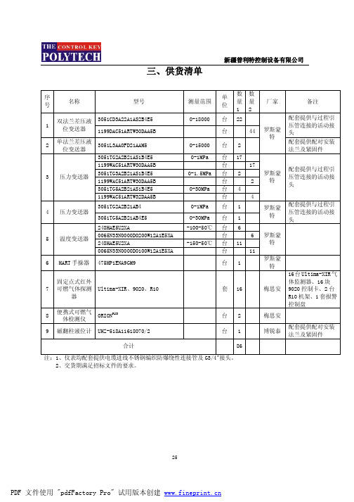
0-18000 0-15000
台 22
配套提供与过程引
台
44
罗斯蒙
压管连接的活动接 头
特
台2
配套提供配对安装 法兰及紧固件
0-1MPa 台 17
0-1.5MPa
台 台 台
2
17 2
罗斯蒙 特
配套提供与过程引 压管连接的活动接 头
0-30MPa 台 4
台
4
0-1MPa 0-30MPa
台1 台1
罗斯蒙 特
三、供货清单
新疆普利特控制设备有限公司
序 号
名称
型号
1
双法兰差压液 3051CD3A22A1AS2B4E5 位变送器 1199DAC51ARTW30DAA5B
2
单法兰差压液 位变送器
罗斯蒙特1199远传毛细管选型
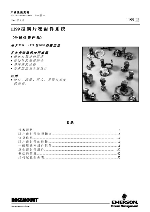
产品性能资料00813-0100-4016 ,DA 版本2002 年 5 月1199 型1199 型膜片密封件系统(全球供货产品)用于 3051 、1151 与 2088 型变送器扩大变送器的应用范围•极热与极冷的温度•腐蚀性的测量场合•易堵塞的过程•要求清洁卫生的场合应用•液位、流量、压力、界面与密度的测量。
目录技术规格 (3)膜片密封件选择指南 (5)订货信息 (9)膜片密封件的连接 (10)一般用途密封件组件 (16)卫生密封件组件 (37)概括的信息 (42)结构配置数据表 (52)产 品 性 能 资 料 00813-0100-4016 ,DA 版 本1199 型 2002 年 5 月全 球 供 货 产 品 之 广 首 屈 一 指采 用 1199 型 膜 片 密 封 件 的 变 送 器 规 格1199 型 膜 片 密 封 件 可 组 装 到 3051 、1151 及 2088 型 差 压 、 表 压 与 绝 对 压 力 变 送 器 及 液 位 变 送 器 上 。
有 关 更 多 信 息 , 请 在 定 购 1199 型 膜 片 密 封 件 之 前 , 查 阅 下 列 产 品 性 能 资 料 :1199 型 膜 片 密 封 件 系 统 提 供 世 界 最 广 泛 的 产 品 供 货 品 种 与 规 格 , 以 满 足 你 对 测量 与 应 用 的 要 求 。
本 产 品 性 能 资 料 重 点 介 绍 各 种 各 样 的 过 程 连 接 型 式 、 直 接 安装 或 毛 细 管 系 统 , 以 及 可 提 供 的 各 种 结构 材 料 。
证 明 是 完 全 整 定 了 的 系 统 , 为 差 压- 液 位 装 置 提 供 最 好 的 工 程 实 践 罗 斯 蒙 特 股 份 有 限 公 司 提 供 市 场 上 唯 一 整 定 了 的 系 统 (Tuned-System) 。
用 此 整 定 了 的 系 统 直 接 安 装 变 送 器 将 导 致 : • 变 送 器 安 装 费 用 减 少 20% • 总 的 系 统 性 能 改 善 10% • 时 间 响 应 改 善 80% 以 上 。
罗斯蒙特选型样本

罗斯蒙特1199 远传膜片系统(全球供货系列产品)用于罗斯蒙特3051S、 3051 、1151 与 2088 型变送器扩大压力变送器应用范围•极热与极冷的温度•腐蚀性的测量场合•易堵塞的过程•要求清洁卫生的场合应用•液位、流量、压力、界面与密度的测量。
目录技术规格 (3)远传膜片选择指南 (5)订货信息 (9)远传膜片的连接 (10)一般用途膜片组件 (16)综合技术资料 (58)全球最完整的供货实力罗斯蒙特 1199 型远传膜片系统提供世界最广泛的产品品种与规格,满足各种测量与应用的要求。
本产品选型资料重点介绍罗斯蒙特 1199 型远传膜片各种过程连接结构形式、直接安装或毛细管系统,以及各种结构材料。
经验证明Tuned-Systems™系统为差压-液位装置提供最佳的工程质量当前市场上只有罗斯蒙特有能力提供优化非平衡系统(Tuned-System)。
采用此系统可带来 :•变送器安装费用减少 20%•总的系统性能提高 10%•时间响应特性改善 80%以上。
仪表工程软件Instrument Toolkit :•计算远传膜片系统的温度指标与响应时间•帮助第一次及以后每次正确选型远传膜片系统要了解关于仪表工程软件更多的内容,详见第 68 页。
要了解关于优化非平衡系统(Tuned-System) 更多的内容,详见第 60 页。
可选用罗斯蒙特1199 型远传膜片的压力变送器类型罗斯蒙特 1199 型远传膜片可组装到罗斯蒙特 3051S、3051 、1151 及 2088 型差压、表压 与绝压变送器及液位变送器上。
有关详细信息,请在定购罗斯蒙特 1199 型远传膜片前,查阅下列产品选型资料:罗斯蒙特 3051S 型压力变送器规模可变的压力、流量与液位测量解决方案,实现了安装与维护的最佳应用实践。
罗斯蒙特 3051 型压力变送器全面领先的性能、灵活的共平面(Coplanar™)平台、5 年稳定性保证。
罗斯蒙特 3095MV 型质量流量变送器精确地测量差压、静压与过程温度,完全实时补偿计算质量流量。
1151选型样本
贮存温度
-20 至 185℉(-29 到 85℃)
静/过压极限:
1151DP 施加 0(绝对压力)~13.76MPa 压力到变送器任意一侧,变送器不损坏;法兰可承受 68.9MPa 压力;正常工作压力应在 3.45kPa(绝对压力)至变送器量程上限
1151AP 施加 0(绝对压力)~13.78MPa 压力变送器不损坏;法兰可承受 68.9MPa 压力;正常工作压 力应在 0kP(绝对压力)至变送器量程上限
3
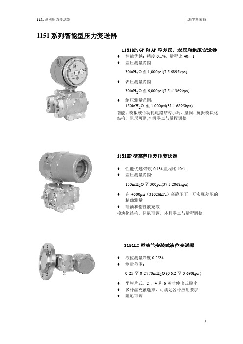
1151 系列压力变送器
上海罗斯蒙特
1650 1500
1000
负载电阻(Ω)
500 250
非工作区
12
24
工作区
注:HART通讯要求负载不低 于250Ω,不高于1100Ω
仅输出4~20mA DC
4~20mA DC及HART通讯 45 工作电压(V)
负载特性图
输出显示:
模拟表头:采用 2 英寸(50.8mm)表盘,插接式安装结构,线形或平方根,0-100%刻度,
数据组态(智能型) EEPROM 存储的所有组态,特性化及数字微调的参数,存储器为非易失性的,因此即使断
电,所以存储的数据仍能完好保存,以随时实现只能通讯.
数/模转换(智能型) 过程变量以数字数据方式存贮,可进行精确地修正和工程单位转换,之后经修正的数据
被转换成一个模拟输出信号。HART 手操器可直接存取传感器的数字信号,而不需数/模转换
150inH2O 至 1,000psi(37.4-6895kpa) 智能、模拟或低功耗电路结构小巧、坚固、抗振模块化 结构,阻尼可调,本机零点与量程调整
1151HP 型高静压差压变送器
♦ 性能优越:精度 0.1%,量程比 40:1 ♦ 差压测量范围:
罗斯蒙特阀组选型资料和尺寸图

Product Data SheetMarch 201700813-0100-4733, Rev PF⏹Factory assembled, leak-tested, and calibrate⏹Full breadth of offering including integral, in-line, and conventional ⏹Integral design enables “flangeless” connection to instrument ⏹Block and bleed, 2-, 3-, and 5-valve configurations ⏹Compact, lightweight design ⏹Easy in-process calibration ⏹Direct-mount capability⏹Available in NACE ®-compliant materials of constructionRosemount ™ ManifoldsRosemount Manifolds March 2017 Selection guideRosemount 305 Integral ManifoldSee “Rosemount mounting brackets” on page28.⏹Assembles directly to transmitter, eliminating need for flange⏹2-, 3-, and 5-valve configuration⏹Available with vertical or horizontal process connections⏹Compact, lightweight assembly⏹Factory assembled, seal-tested, and calibrated⏹50 percent fewer leak points than conventional transmitter toflange to manifold interface⏹Female NPT process connectionsRosemount 306 In-line ManifoldSee “Rosemount mounting brackets” on page28.⏹Assembled directly to in-line pressure transmitters orRosemount Wireless Pressure Gauge⏹Block-and-bleed and 2-valve configurations⏹Male or female threaded NPT process connectionRosemount 306 In-Line ManifoldRosemount 304 ConventionalManifoldSee “Rosemount mounting brackets” on page28.⏹Attaches to transmitter flange⏹2-, 3-, and 5-valve configurations⏹Traditional (Flange ϫ Flange, Flange ϫ NPT) and wafer styles⏹Factory assembled, seal-tested, and calibratedRosemount 304 Conventional Manifold - Traditional StyleRosemount 304 Conventional Manifold - Wafer StyleContentsValve configuration . . . . . . . . . . . . . . . . . . . . . . . . . . . . . . . 3Ordering information . . . . . . . . . . . . . . . . . . . . . . . . . . . . . 4Specifications . . . . . . . . . . . . . . . . . . . . . . . . . . . . . . . . . . .13Dimensional drawings . . . . . . . . . . . . . . . . . . . . . . . . . . . .19 Rosemount 305 Integral Manifold -Coplanar StyleRosemount 305 Integral Manifold -Traditional StyleRosemount ManifoldsMarch 2017Valve configurationBlock-and-bleedThe block-and-bleed configuration is available on theRosemount 306 Manifold for use with in-line gage and absolute pressure transmitters. A single isolate valve provides instrument isolation and a bleed screw provides drain/vent capabilities.Rosemount 306 ManifoldTwo-valveThe 2-valve configuration is available on Rosemount 305, 306, and 304 Manifolds for use with absolute and gage pressure transmitters. An isolate valve provides instrument isolation and a drain/vent valve allows venting, draining, or calibration.Rosemount 305 and 306 ManifoldsRosemount 304 ManifoldThree-valveThe 3-valve configuration is available on Rosemount 305 and 304 Manifolds for use with differential pressure and multi-variable transmitters. Two isolate valves provide instrument isolation, and one equalize valve is positioned between the high and low process connections.Rosemount 305 ManifoldRosemount 304 (Traditional) ManifoldRosemount 304 (Wafer) ManifoldNoteVent ports receive plastic caps to protect threaded connections unless otherwise noted.NotePlugged connections receive 1/4-in. NPT plugs unless otherwisenoted.Rosemount Manifolds March 2017Five-valveThe 5-valve configuration is available on Rosemount 305 and 304 Manifolds for use with differential pressure and multivariable transmitters. Two isolate valves provide instrument isolation and one equalize valve is positioned between the high and low process connections. In addition, two drain/vent valves allow for controlled venting, 100 percent capture of vented or drained process, and simplified in-process calibration capability.Rosemount 305 Manifolds and 304 (Wafer)Five-valve natural gasThe 5-valve natural gas configuration is available on the Rosemount 305 and 304 Manifolds for use with differential pressure and multivariable transmitters. Two isolate valves provide instrument isolation and a single drain/vent valve allows for controlled venting, 100 percent capture of vented or drained process, and simplified in-process calibration capability. In addition, two equalize valves provide extra protection from leaking to ensure DP signal integrity.⏹“NG” option includes wide handle pattern and soft seats for ease of use as well as a larger bore to reduce plugging Rosemount 305 Manifolds and 304 (Traditional)NoteVent ports receive plastic caps to protect threaded connections unless otherwise noted.NotePlugged connections receive 1/4-in. NPT plugs unless otherwise noted.Ordering information Rosemount Manifolds can be ordered as a stand-alone product or as an integrated assembly attached to a transmitter.Stand-alone manifold1.Reference the “Selection guide” on page2 for assistanceon choosing the type of manifold.2.Specify a completed model number by referencing theapplicable ordering table for the selected manifold type:⏹Rosemount 305 Integral Manifold, see page5.⏹Rosemount 306 In-line Manifold, see page8.⏹Rosemount 304 Conventional Manifold, see page10.Transmitter/manifold assembly1.Specify a completed Rosemount transmitter modelnumber by referencing the applicable product data sheet.2.Specify a completed manifold model number byreferencing the applicable ordering table for the selectedmanifold type:⏹Rosemount 305 Integral Manifold, see page5.⏹Rosemount 306 In-line Manifold, see page8⏹Rosemount 304 Conventional Manifold, see page10.3.Verify the transmitter model number contains the correct“Process Connection” code or “Manifold Option” code for the desired transmitter manifold assembly (see Table 1).Table 1. Ordering Codes for a Transmitter/ManifoldAssemblyTransmitter ManifoldProcessconnection code“Manifold”option codeRosemount3051S305A11N/A306A11N/A304A12N/ARosemount3051/2051305N/A S5306N/A S5304N/A S6Rosemount2088305N/A N/A306N/A S5304N/A N/AAlisa Peng whdkmsale@ wechat:whdkmsaleRosemount Manifolds March 2017Specification and selection of product materials, options, or components must be made by the purchaser of the equipment. See page13 for more information on material selection.Table 2. Rosemount 305 Integral Manifold Ordering InformationThe starred offerings (★) represent the most common options and should be selected for best delivery. The non-starred offerings are subject to additional delivery lead time.Model Product description0305Integral manifoldManufacturerR Rosemount★Manifold styleC Coplanar★T Traditional★M Traditional (DIN-compliant flange)★Manifold type22-valve★33-valve★5(1)5-valve★6(2)5-valve natural gas metering pattern★7(2)(3)2-valve (per ASME B31.1 [ANSI] power and piping code)8(2)(3)3-valve (per ASME B31.1 [ANSI] power and piping code)9(2)(3)5-valve (per ASME B31.1 [ANSI] power and piping code)Body(4)Bonnet Stem and tip/ball2316 SST/316L SST316 SST316 SST★3(5)Alloy C-276Alloy C-276Alloy C-2764(5)(6)Alloy 400Alloy 400Alloy 400Process connection styleA(7)1/4–18 NPT female ★B(8)1/2–14 NPT female★Packing material1(9)PTFE★2(10)Graphite-basedValve seat1 Integral★5Soft POM (only available with natural gas metering pattern)★OptionsExtended product warrantyWR33-year limited warranty★WR55-year limited warranty★Rosemount Manifolds March 2017Table 2. Rosemount 305 Integral Manifold Ordering InformationThe starred offerings (★) represent the most common options and should be selected for best delivery. The non-starred offerings are subject to additional delivery lead time.Mounting bracketsB1Bracket for 2-in. pipe mounting, CS bolts★B3(11)Flat bracket for 2-in. pipe mounting, CS bolts★B4SST mounting bracket for 2-in. pipe mounting, 300 SST bolts★B7B1 bracket with 316 SST bolts★B9(11)B3 bracket with 316 SST bolts★BA316 SST B1 bracket with 316 SST bolts★BC(11)316 SST B3 bracket with 316 SST bolts★BE316 SST B4 bracket with 316 SST bolts★BF CS panel mount bracket★BG300 SST panel mount bracket★Bolt materialsL4(12)Austenitic 316 SST bolts★L5ASTM A193, Grade B7M bolts★L8ASTM A193, Class 2, Grade B8M bolts★Cleaning(13)P2Cleaning for special services★Material recommendations for NACE(5)(14)SG Sour gas (meets NACE MR0175/ISO 15156, MR0103/ISO 17495)★Adapters(15)DF1/2–14 NPT female flange adapter★DQ12 mm ferrule tube flange adapterProcess flowmeter configurationPF Relocated equalize valve for 9295 Process FlowmeterProcess flange bolting connection(16)HK10 mm (M10) process flange bolting connection★HL12 mm (M12) process flange bolting connection★Typical coplanar integral manifold model number: 305 R C 3 2 B 1 1 B41.Not available with traditional manifold style T.2.Only available with coplanar manifold style code C.3.Only available with 316 SST materials of construction code 2 and graphite-based packing code 2.4.Refer to Table 13 on page18 for additional detail on process wetted materials of construction.5.Materials of construction comply with recommendations per NACE MR0175/ISO 15156 for sour oil field production environments. Environmental limits apply tocertain materials. Consult latest standard for details. Selected materials also conform to NACE MR0103/ISO 17495 for sour refining environments.6.Includes Alloy C - 276 drain vents.7.Only available with traditional manifold style codes T and M.8.Not available with traditional manifold style code M. Manifold style code T does not include mounting holes on process flange.9.Includes PTFE tape on drain/vent valves and plugs.Rosemount Manifolds March 201710.Includes graphite tape on drain/vent valves and plugs.11.Not compatible with the Rosemount 3095 Transmitter.12.Not available with ASME B31.1 manifold type codes 7, 8, and 9.13.Not available with graphite-based packing material code 2.14.Only allowed with material of construction code 2.15.Only allowed with traditional manifold style codes T and M. Not allowed with graphite-based packing code 2.16.Only available with traditional manifold style code M.Rosemount Manifolds March 2017 Specification and selection of product materials, options, or components must be made by the purchaser of the equipment. Seepage13 for more information on material selection.Table 3. Rosemount 306 Pressure Manifold Ordering InformationThe starred offerings (★) represent the most common options and should be selected for best delivery. The non-starred offerings are subject to additional delivery lead time.Model Product description0306Pressure manifoldManufacturerR Rosemount★Manifold styleT Threaded★Manifold type1Block-and-bleed★22-valve★3(1)2-valve (per ASME B31.1 power piping code)Body(2)Bonnet Stem and tip/ball2316 SST/316L SST316 SST316 SST★3(3)(4)Alloy C-276Alloy C-276Alloy C-276Process connectionAA1/2–14 male NPT process connection for in-line transmitter ★AW1/2–14 male NPT process connection for Rosemount Wireless Pressure Gauge★BA(3)1/2–14 female NPT process connection for in-line transmitter★BW1/2–14 female NPT process connection for Rosemount Wireless Pressure Gauge★Packing material1(5)PTFE★2(6)Graphite-basedValve seat1Integral★OptionsExtended product warrantyWR33-year limited warranty★WR55-year limited warranty★Cleaning(7)P2Cleaning for special servicesRosemount ManifoldsMarch 2017Material recommendations for NACE (4)(8)SGSour gas (meets NACE MR0175/ISO 15156, MR0103/ISO 17495)★Typical integral manifold model number: 306 R T 2 2 BA 1 11.Only available with 316 SST materials of construction and graphite-based packing.2.Refer to Table 14 on page 18 for additional detail on process wetted materials of construction.3.Not available with block-and-bleed manifold type.4.Materials of Construction comply with recommendations per NACE MR0175/ISO 15156 for sour oil field production environments. Environmental limits apply to certain materials. Consult latest standard for details. Selected materials also conform to NACE MR0103/ISO 17495 for sour refining environments.5.Includes PTFE tape on drain/vent valves and plugs.6.Includes graphite tape on plugs.7.Not available with graphite-based packing material code 2.8.Only allowed with material of construction code 2.Table 3. Rosemount 306 Pressure Manifold Ordering InformationThe starred offerings (★) represent the most common options and should be selected for best delivery. The non-starred offerings are subject to additional delivery lead time.Rosemount Manifolds March 2017 Specification and selection of product materials, options, or components must be made by the purchaser of the equipment.See page13 for more information on material selection.Table 4. Rosemount 304 Conventional Manifold Ordering InformationThe starred offerings (★) represent the most common options and should be selected for best delivery. The non-starred offerings are subject to additional delivery lead time.Model Product description0304Conventional manifoldManufacturerR Rosemount★Manifold styleT Traditional (flange ϫ flange or flange ϫ NPT)★W(1)WaferManifold type2(2)2-valve★33-valve★5(3)5-valve★6(2)5-valve natural gas metering pattern★7(2)(4)2-valve (per ASME B31.1 [ANSI] power and piping code)8(2)(4)3-valve (per ASME B31.1 [ANSI] power and piping code)Body(5)Bonnet Stem Tip2316 SST/316L SST316 SST316 SST316 SST★5CS316 SST316 SST316 SST★Process connection styleB1/2–14 NPT★F(2)Flanged★Packing/stem seal material1(6)PTFE★2(1)(7)Graphite-based3(8)FKM Elastomer O-ring★Bolts1For assembly to Rosemount 2051/3051 Traditional Flange★2For assembly to Rosemount 2051/3051 DIN-compliant Traditional Flange★3For assembly to Rosemount2051/3051 Coplanar™ Flange★Table 4. Rosemount 304 Conventional Manifold Ordering InformationThe starred offerings (★) represent the most common options and should be selected for best delivery. The non-starred offerings are subject to additional delivery lead time.OptionsGas-metering configurationNG(9)Wide handle pattern, 3/8-in. bore, soft POM seat★Extended product warrantyWR33-year limited warranty★WR55-year limited warranty★Mounting bracketsVC(2)Manifold heavy duty mounting bracket, CS for traditional style★VS(2)Manifold heavy duty mounting bracket, 316 SST for traditional style★B4(3)Manifold SST mounting bracket for 2-in. pipe mount with series 300 SST bolts for wafer style★Adapters and connectors(10)DF1/2–14 NPT female flange adapter★DT1/2-in. ferrule tube flange adapter★DQ12mm ferrule tube flange adapter★DV(11)1/2–14 NPT male non-stabilized connectors★DH(11)1/2–14 NPT male stabilized extended connectors★Dielectric isolator kitsG2(12)Dielectric isolators and bolt sleeves for connectors★Bolt materialL4(13)Austenitic 316 SST bolts★L5ASTM A193, Grade B7M bolts★L8ASTM A193, Class 2, Grade B8M bolts★Material recommendations for NACE(1)(14)SG Sour gas (meets NACE MR0175/ISO 15156, MR0103/ISO 17954)★Cleaning(15)P2Cleaning for special serviceHeater block kits(16)SB Steam block kit, 1/4-in. NPT connection★Typical model number: 0304 R T 3 2 B 1 1 VS1.Only allowed with material of construction code2.2.Not available with wafer manifold style code W.3.Not available with traditional manifold style code T.4.Only available with 316 SST materials of construction code 2 and graphite-based packing code 2.5.Refer to Table 15 on page18 for additional detail on process wetted materials of construction.6.Includes PTFE tape on drain/vent valves and plugs.7.Includes graphite tape on plugs.8.Only available with option code NG.9.Only available with manifold type code 6.10.Only allowed with both manifold style code T and process connection code F. Not allowed with Graphite-based packing code 2.11.Only available with manifold style code 6.12.Only available with option codes DV and DH.13.Not available with manifold type codes 7, 8.14.Materials of construction comply with recommendations per NACE MR0175/ISO 1516 for sour oil field production environments. Environmental limits apply tocertain materials. Consult latest standard for details. Selected materials also conform to NACE MR0103/ISO 17495 for sour refining environments.15.Not available with Graphite-based packing material code 2.16.Not available with manifold type code 6.SpecificationsMaterial selectionEmerson ™ provides a variety of Rosemount product with various product options and configurations including materials ofconstruction that can be expected to perform well in a wide range of applications. The Rosemount product information presented is intended as a guide for the purchaser to make an appropriate selection for the application. It is the purchaser’s sole responsibility to make a careful analysis of all process parameters (e.g. all chemical components, temperature, pressure, flow rate, abrasives, contaminants), when specifying product, materials, options and components for the particular application. Emerson is not in a position to evaluate or guarantee the compatibility of the process fluid or other process parameters with the product, options, configuration or materials of construction selected. For more information on material compatibility, refer to the Material Selection Technical Note.Pressure and temperature ratingsFigure 1. Rosemount 305 Integral ManifoldsTable 5. Rosemount 305 Integral Manifolds (1)1.Except option HK:PTFE, integral seat: 2324 psi @ 200 °F (160 bar @ 93 °C), 1680 psi @ 400 °F (116 bar @ 204 °C)Graphite, integral seat: 2324 psi @ 200 °F (160 bar @ 93 °C), 1125 psi @ 750 °F (78 bar @ 399 °C)PackingSeatPressure and temperature ratingsPTFE Integral 6092 psi @ 200 °F (420 bar @ 93 °C)4000 psi @ 400 °F (276 bar @ 204 °C)PTFE Soft POM 6092 psi @ 200 °F (420 bar @ 93 °C)GraphiteIntegral 6092 psi @ 200 °F (420 bar @ 93 °C)1500 psi @ 750 °F (103 bar @ 399 °C)Graphite (ASME B31.1)Integral6092 psi @ 100 °F (420 bar @ 38 °C)3030 psi @ 1000 °F (201 bar @ 538 °C)Figure 2. Rosemount 306 In-line ManifoldsTable 6. Rosemount 306 In-line ManifoldsPackingSeatPressure and temperature ratingsPTFE Integral 10000 psi @ 85 °F (689 bar @ 29 °C)4000 psi @ 400 °F (276 bar @ 204 °C)GraphiteIntegral 6000 psi @ 200 °F (414 bar @ 93 °C)1500 psi @ 750 °F (103 bar @ 399 °C)Graphite (ASME B31.1)Integral6000 psi @ 100 °F (414 bar @ 38 °C)3030 psi @ 1000 °F (201 bar @ 538 °C)Figure 3. Rosemount 304 Conventional ManifoldsTable 7. Rosemount 304 Conventional ManifoldsPackingSeatPressure and temperature ratingsPTFE (1)1.Maximum working pressure limited to 4500 psi (310 bar) with G2 option.Integral 6000 psi @ 200 °F (414 bar @ 93 °C)4000 psi @ 400 °F (276 bar @ 204 °C)Graphite - wafer Integral 6000 psi @ 200 °F (414 bar @ 93 °C)1500 psi @ 750 °F (103 bar @ 399 °C)Graphite - flanged (SST)Integral 6000 psi @ 200 °F (414 bar @ 93 °C)1500 psi @ 1000 °F (103 bar @ 538 °C)Graphite - flanged (CS)Integral 6000 psi @ 200 °F (414 bar @ 93 °C)1500 psi @ 800 °F (103 bar @ 427 °C)Graphite (ASME B31.1)Integral 6000 psi @ 100 °F (414 bar @ 38 °C)3030 psi @ 1000 °F (201 bar @ 538 °C)PTFE POM 4500 psi @ 212F (310 bar @ 100 C)FKM O-ringPOM4500 psi @ 212 F (310 bar @ 100 C)Instrument connectionsO-ringsFigure 5. Rosemount 304 Conventional ManifoldTable 8. Manifold - Transmitter InterfaceModelConnectionRosemount 305 Integral Manifold Mounted directly to coplanar sensor module of transmitter, 1.3-in. (287 mm) center-to-center process isolatorsRosemount 306 In-line Manifold 1/2–14 male NPT for In-line transmitters 1/2-14 female NPT for Rosemount Wireless Pressure GaugeRosemount 304 Conventional ManifoldMounted to traditional transmitter flange, 21/8-in. (54 mm) center-to-center connection per IEC 61518, Type B shut-off device (without spigot)1.Available in packing material code 1 (PTFE) or code 2 (Graphite).Process connectionsVent port connections1/4–18 female NPTManifold boltsStandard material is plated Carbon Steel per ASTM A449, Type 1Alternative bolt materials offered through option codes:⏹L4 for Austenitic 316 stainless steel bolts ⏹L5 for ASTM A193, Grade B7M Bolts ⏹L8 for ASTM A193, Grade B8M Class 2 boltsTable 9. Rosemount 305 Integral ManifoldStyleConnectionCoplanar 1/2–14 female NPTTraditional1/4–18 female NPT(process adapters optional)Table 10. Rosemount 306 In-line ManifoldStyleConnectionBlock-and-bleed 1/2–14 male NPT(1)1.1/2-14 female NPT option only available with Wireless Pressure Gauge.2-valve1/2–14 NPT (male or female)Table 11. Rosemount 304 Conventional ManifoldStyleConnectionFlange by pipe 1/2–14 female NPTFlange by flange 21/8-in. (54 mm) center-to-centerconnection (process adapters required)Wafer1/2-14 female NPTTable 12. Adapters and ConnectorsOption DescriptionImageDF1/2-14 NPT female flange adapter•Available with Rosemount 305Integral and 304 Conventional ManifoldsDT1/2-in. ferrule tube flange adapter•Available with Rosemount 304 Conventional ManifoldDQ12mm ferrule tube flange adapter•Available with Rosemount 305 Integral and 304 Conventional ManifoldsDV (1)Non-stabilized connector•3.00-in.•No stabilizing foot•Includes assembly hardwareDH (1)Stabilized extended connectors•4.75-in.•Stabilizing foot•Includes assembly hardwareG2(1)(2)Dielectric isolators•Rated to 2500 VDC and 5 mega-Ohms•Includes bolts sleeves and assembly hardware1.Only allowed with both Rosemount 304 Manifold type code 6 and process connection code F. Not allowed with Graphite- based packing code2.2.Maximum working pressure of assembly limited to 4500 psi (310 bar), 3626 psi (250 bar) at –20 °F (–29 °C), and 3626 psi (250 bar) at 150 °F (66 °C).Table 12. Adapters and ConnectorsOption DescriptionImageMaterials of construction Process wetted TypicalFigure 6. Typical Rosemount Manifold Valve Estimated weightTable 13. Rosemount 305 Integral ManifoldComponent Option 2Option 2with SGOption 3Option 4Body 316 SST/316L SST316 SST/316L SSTAlloy C-276Alloy 400Ball/tip 316 SST/316Ti SSTAlloyC-276Alloy C-276Alloy 400Stem316 SST AlloyC-276Alloy C-276Alloy 400Packing PTFE/GraphitePTFE/GraphitePTFE/GraphitePTFE/GraphiteBonnet316 SST316 SST Alloy C-276Alloy 400 Pipe plug316 SST316 SST Alloy C-276Alloy 400Drain/vent valve 316 SSTAlloyC-276Alloy C-276Alloy 400Table 14. Rosemount 306 In-line ManifoldComponent Option 2Option 2with SGOption 3Body 316 SST/316L SST316 SST/316L SSTAlloy C-276Ball/tip 316 SST/316Ti SSTAlloy C-276Alloy C-276Stem316 SST Alloy C-276Alloy C-276 Packing PTFE/Graphite PTFE/Graphite PTFE/Graphite Bonnet316 SST316 SST Alloy C-276 Pipe plug316 SST316 SST Alloy C-276Bleed screw 316 SST/316Ti SSTAlloy C-276Alloy C-276Table 15. Rosemount 304 Conventional ManifoldComponent Option 2Option 2with SGOption 5Body 316 SST/316L SST316 SST/316L SSTCSBall/tip 316 SST/316Ti SSTAlloy C-276316 SSTStem316 SST Alloy C-276316 SSTPacking PTFE/GraphitePTFE/GraphitePTFEBonnet316 SST316 SST CS Pipe plug316 SST316 SST CS A. BonnetB. StemC. PackingD. Ball/tipE. BodyTable 16. Rosemount 305 Integral Manifold Description Weight2-valve coplanar 4.5 lbs (2.0 kg) 2-valve traditional 6.0 lbs (2.7 kg) 3-valve coplanar 4.7 lbs (2.1 kg) 3-valve traditional 6.0 lbs (2.7 kg) 5-valve coplanar 6.5 lbs (3.0 kg) Table 17. Rosemount 306 In-line Manifold Description Weight Block-and-bleed 1.1 lbs (0.5 kg) 2-valve 2.5 lbs (1.1 kg) Table 18. Rosemount 304 Conventional Manifold Description Weight2-valve traditional flange ϫ NPT 5.0 lbs (2.3 kg) 2-valve traditional flange ϫ flange 5.5 lbs (2.5 kg) 3-valve traditional flange ϫ NPT 5.2 lbs (2.4 kg) 3-valve traditional flange ϫ flange 5.7 lbs (2.6 kg) 3-valve wafer flange ϫ NPT 4.0 lbs (1.8 kg) 5-valve wafer flange ϫ NPT 5.7 lbs (2.6 kg) 5-valve traditional flange ϫ NPT 5.7 lbs (2.6 kg) 5-valve traditional flange ϫ flange 5.7 lbs (2.6 kg)Dimensional drawingsRosemount 305 Manifold(1)Figure 7. Rosemount 305RC 2-Valve Coplanar Style ManifoldA. 1/2–14 NPT on manifold for process connection, 1/4–18 NPT for test/vent connectionDimensions are in inches (millimeters).Figure 8. Rosemount 305RC 3-Valve Coplanar Style ManifoldsA. Drain/vent valveB. 1/2–14 NPT on manifold for process connections, 21/8-in. center-to-centerDimensions are in inches (millimeters).1.Manifold handle assembly may vary slightly from image shown. All valve handle assemblies provide the same function and meet all stated drawing dimensions.Figure 9. Rosemount 305RC 5-Valve Coplanar Style ManifoldA. 1/2–14 NPT on manifold for process connections, 21/8-in. center-to-center, 1/4–18 NPT for test/vent connection Dimensions are in inches (millimeters).Figure 10. Rosemount 305RT 2-Valve Traditional Style ManifoldA./2–14 NPT on optional process adapterB. 1/4–18 NPT on traditional manifold for process connection without the use of a process adapter Dimensions are in inches (millimeters).Figure 11. Rosemount 305RT 3-Valve Traditional Style ManifoldFigure 12. Rosemount 305RM 2-Valve Traditional DIN Style ManifoldA. Drain/vent valveB. 1/2–14 NPT on optional process adapter (1)1.Adapters can be rotated to give adapter connection centers of 2.0 (51), 2.125 (54), or 2.25 (57).C. 1/4–18 NPT on traditional manifold for process connections without the use of process adaptersDimensions are in inches (millimeters).A. 1/2–14 NPT on optional process adapterC. 1/4–18 NPT vent connection B. 1/4–18 NPT on traditional manifold for process connection without the use of a process adapter Dimensions are in inches (millimeters).Figure 13. Rosemount 305RM 3-Valve Traditional DIN Style ManifoldFigure 14. Rosemount 305RM 5-Valve Traditional DIN Style ManifoldB. 1/2–14 NPT on optional process adapter (1)1.Adapters can be rotated to give adapter connection centers of 2.0 (51), 2.125 (54), or 2.25 (57).4D. 0.75 (19) clearance for cover removalDimensions are in inches (millimeters).A. 1/2–14 NPT on optional process adapter (1)B. 1/4–18 NPT on traditional manifold for process connections without the use of process adapters Dimensions are in inches (millimeters).1.Adapters can be rotated to give adapter connection centers of 2.0 (51), 2.125 (54), or 2.25 (57).Rosemount 306 Manifold (1)Figure 15. Rosemount 306RT Pressure Style Manifold (3051S_T Shown)(2)Rosemount 304 Manifold (1)Figure 16. Rosemount 304RT 2-Valve Flange ϫ NPT Conventional Manifold1.Manifold handle assembly may vary slightly from image shown. All valve handle assemblies provide the same function and meet all stated drawing dimensions.Block-and-bleed style2-valve styleA. Bleed screw (unspecified dimension) - not designed for accessory attachments. C. 1/2–14 NPT female NPT process connection (code BA)B. 1/4-in. vent connection–pipe plug supplied with manifold, but not installed at factory (pipe plug supplied loose)Dimensions are in inches (millimeters).2.Manifold valve orientation may vary with respect to transmitter mounting holes.Instrument sideProcess sideA. 0.281 mounting holes (2)B. 1/4-in. NPT test (plugged)C. 1/2-in. NPT process connection on 2.125 (54) centers (2)Dimensions are in inches (millimeters).∅。
罗斯蒙特1199远传装置选型

杭州经纶自动化工程有限公司
1
1199 型 全球供货产品之广首屈一指
1199 型 膜 片 密 封 件 系 统 提 供 世 界 最 广 泛 的产品供货品种与规格,以满足你对测 量与应用的要求。本产品性能资料重点 介绍各种各样的过程连接型式、直接安 装或毛细管系统,以及可提供的各种结 构材料。 证 明 是 完 全 整 定 了 的 系 统 , 为 差 压- 液 位装置提供最好的工程实践 罗斯蒙特股份有限公司提供市场上唯一 整 定 了 的 系 统 (Tuned-System) 。 用 此 整 定 了的系统直接安装变送器将导致: 变 送 器 安 装 费 用 减 少 20% 总 的 系 统 性 能 改 善 10% 时 间 响 应 改 善 80% 以 上 。 请 用 仪 表 成 套 工 具 (Instrument Toolkit®) SOAP 2000 软件计算你应用此系统产生的差异 。 SOAP 2000 软 件 : 精确地计算性能与响应时间 首先实现,每一次为你确定正确的 密封件系统。 要 了 解 关 于 整 定 系 统 (Tuned-System) 更 多 的 内 容 , 请 参 阅 第 44 页 的“ 整 定 系 统 对 比 平 衡 系 统”。 要 了 解 关 于 SOAP 2000 软 件 更 多 内 容 , 请 参 阅 第 50 页 的“ 仪 表 成 套 工 具 (Instrument Toolkit®) SO算远传密封件系统的 性能并确认型号的结构配置。
物理规格
密封件、充灌液与毛细管
CF3M(316L 不 锈 钢 的 铸 造 型 式 , 根 据 ASTM-A743 规 定 的 材 料) 或 CF8M(316 不 锈 钢 的 铸 造 型 式 , 根 据 ASTM-A743 规 定 的 材 料) 的 技 术 规 格 。
1151选型样本
测出一个正过压值,则模拟信号输拟信号输出 20.8mA
变送器保护:使用变送器保护功能可防止修改变送器的组态,包括防止本机零点和量程调整.
保护功能由内部开关设置
温度特性:
线路板工作温度
-40 至 185℉(-40 至 85℃)
传感器工作温度
Hale Waihona Puke 充硅油-40 至 220℉(-40 至 104℃)
充惰性液
0 至 160℉(-18 至 71℃)
1151GP 量程为 6.89MPa 以下的施加 0(绝对压力)~13.8MPa;量程为 20.68MPa 的施加 0(绝对压 力)~31.2MPa;量程为 41.37MPa,施加 0(绝对压力)~51.45MPa 变送器无损坏。正常工 作压力在 3.45kPa(绝对压力)至变送器量程上限,法兰可承受 68.9MPa 压力
4
1151 系列压力变送器
上海罗斯蒙特
技术参数
精 确 度:
1151GP/DP 量程为 3、4、5 在量程比为 1:1 到 10:1 时,为调校量程的±0.1% 在量程比为 10:1 到 40:1 时,为±0.05(1+0.1URL/量程)%量程 量程为 2、6、7、8、9、0 在量程比为 1:1 到 10:1 时,为调校量程的±0.15% 在量程比为 10:1 到 40:1 时,为±0.075(1+0.1URL/量程)%量程
线路板模块(智能型) 变送器线路板模块采用专用集成电路(ASICS)和表面封装技术。线路块接收来自传感器
膜头的数字信号和修正系数后,对信号进行修正和线性化。线路板模块的输出部分将数字信 号转换成一个模拟信号输出,并可与 HART 手操器通讯。可选的液晶表头插入线路板上,可显 示以压力工程单位或百分比为单位的数字输出。
罗斯蒙特差压液位变送器和 1199 远传密封
50 毫米 /2 英寸 100 毫米 /4 英寸 150 毫米 /6 英寸 仅平齐安装
仅平齐安装
标准
尺寸
额定值
材料
9
可选行业标准 (需要 “ 可选行业标准 ” 选项)
过程灌充液 - 高压侧
25°C (77°F) 时的比重
为什么使用膜片密封件?
密封系统能够可靠地测量过程压力,并防止过程介质 接触变送器膜片。
出现下列情况时应考虑使用变送器 / 膜片密封系统: • 过程温度超出变送器的正常工作范围,而且不 能用导压管把温度调节至极限范围内; • 过程具有腐蚀性,需要频繁更换变送器或使用 特殊结构材料; • 过程中含有悬浮固体颗粒或者具有粘滞性,可 能会堵塞导压管; • 要求使用卫生连接件时; • 要求能够轻松清洗连接件位置,以避免批次间 的污染; • 当参考柱不稳定需要更换湿 / 干柱以减少维护工 作时;或通常需要重新灌充 / 排干时; • 需要测量密度或界面时; • 变送器或导压管中的过程介质可能冻结或凝固 时;
温度限制(2)
标准
A C D H
G(3)(4) N(4) P(3)(4) 低压侧
Syltherm XLT
0.85
704 硅油
1.07
200 硅油
0.93
惰性灌充液
1.85
(卤化烃)
甘油和水
1.13
Neobee M-20
0.92
丙二醇和水混合液 1.02
-75 至 145°C (-102 至 293°F) 0 至 205°C (32 至 401°F) -45 至 205°C (-49 至 401°F) -45 至 160°C (-49 至 320°F)
罗斯蒙特848T温度变送器选型中文样本
85
C
-40
185
F
!"#
C
1.8
F ! C
!"# !" = 0.00385 = 0.003916 Ni 120 0.003 0.003 0.003 0.004 0.03 C C C C C C CCC+
1 0.0054 0.0054 0.0054 0.0072 0.054 F R 0.0025% R - 300 0.011% R - 100 0.00043% R 0.00029% R 0.0025% |R| 0.00054% R 0.0025% |R| 0.00036% R R 0.0036% R 0.0043% |R| R R R 300 100 F F F F
7.5-11.9 mm !" 1/2 NPT
!"
!"#$% !" T1 !"#$ !"#$%!"&'()*+*,-./0-123 ! !"# 848T !"# $%& !ASME B 16.5 ANSI /IEEE C62.41-1991 IEEE 587 ! A2 B3 6 kV / 3 kA 1.2 x 50 S 8 x 20 S ! 6 kV / 0.5 kA 100 kHz ! 4 kV EFT 5 x 50 nS !"#$%
!"#$%&
!"#$%&'()*+,-./012345 !"# !"#$% 848T !"#$ MAI !"MAI !"#$%&'()* !"#$%& !"#$%&
罗斯蒙特涡街样本
比例 / 积分 / 微分 可选 PID 功能块提供通用的 PID 运算法则的成熟运 算。 PID 功能块以供过程变量的前馈控制、过程参数 的报警及控制偏移的输入为特点。 PID 类型 ( 系列或 美国仪器协会 [ISA]) 在微分滤波方面是用户选择的。
累加
标准累加块用于流量累积。
设置
基本设置要求将变送器连接到现场总线网络或 375 手 持通讯器。基金会现场总线兼容的主机会自动建立与 设备的通讯。
8800D 型流量计可容易地用 DeltaV 系统组态。用户 可组态的参数包括:位号、范围值和单位、介质类 型、阻尼、过程密度,管内径 (ID)(1) 及过程温度(1)。 位号信息可被输入到变送器中以允许识别及物理描 述。 32 字符位号用于变送器和每个功能块的识别。
00813-0100-4004, Rev DA 2007 年 2 月
8800D 型
8800DR 型缩径型涡街流量计降低了成本,扩大了流量范围测量
• 罗斯蒙特可靠性 - 在设计上与 8800D 型有相同 的电子部件、传感器和流量计表体。
• 降低成本 - 免除了现场装配和单独焊接大小头 和管道,安装成本降低 50%。
8800D 型
产品样本
00813-0100-4004, Rev DA 2007 年 2 月
8800D 多变量涡街流量计减少了安装成本, 简化了安装工程,并且改善了饱合蒸汽应用性能
• 多变量涡街流量计结构 采用涡街发生体作为热元件套管将温度传感器 嵌入涡街流量计中,从而使涡街传感器和温度 传感器与工艺介质相隔离,便于检验和更换。
/rosemount
8800D 型
产品样本
- 1、下载文档前请自行甄别文档内容的完整性,平台不提供额外的编辑、内容补充、找答案等附加服务。
- 2、"仅部分预览"的文档,不可在线预览部分如存在完整性等问题,可反馈申请退款(可完整预览的文档不适用该条件!)。
- 3、如文档侵犯您的权益,请联系客服反馈,我们会尽快为您处理(人工客服工作时间:9:00-18:30)。
罗斯蒙特1199 远传膜片系统(全球供货系列产品)用于罗斯蒙特3051S、 3051 、1151 与 2088 型变送器扩大压力变送器应用范围•极热与极冷的温度•腐蚀性的测量场合•易堵塞的过程•要求清洁卫生的场合应用•液位、流量、压力、界面与密度的测量。
目录技术规格 (3)远传膜片选择指南 (5)订货信息 (9)远传膜片的连接 (10)一般用途膜片组件 (16)综合技术资料 (58)全球最完整的供货实力罗斯蒙特 1199 型远传膜片系统提供世界最广泛的产品品种与规格,满足各种测量与应用的要求。
本产品选型资料重点介绍罗斯蒙特 1199 型远传膜片各种过程连接结构形式、直接安装或毛细管系统,以及各种结构材料。
经验证明Tuned-Systems™系统为差压-液位装置提供最佳的工程质量当前市场上只有罗斯蒙特有能力提供优化非平衡系统(Tuned-System)。
采用此系统可带来 :•变送器安装费用减少 20%•总的系统性能提高 10%•时间响应特性改善 80%以上。
仪表工程软件Instrument Toolkit :•计算远传膜片系统的温度指标与响应时间•帮助第一次及以后每次正确选型远传膜片系统要了解关于仪表工程软件更多的内容,详见第 68 页。
要了解关于优化非平衡系统(Tuned-System) 更多的内容,详见第 60 页。
可选用罗斯蒙特1199 型远传膜片的压力变送器类型罗斯蒙特 1199 型远传膜片可组装到罗斯蒙特 3051S、3051 、1151 及 2088 型差压、表压 与绝压变送器及液位变送器上。
有关详细信息,请在定购罗斯蒙特 1199 型远传膜片前,查阅下列产品选型资料:罗斯蒙特 3051S 型压力变送器规模可变的压力、流量与液位测量解决方案,实现了安装与维护的最佳应用实践。
罗斯蒙特 3051 型压力变送器全面领先的性能、灵活的共平面(Coplanar™)平台、5 年稳定性保证。
罗斯蒙特 3095MV 型质量流量变送器精确地测量差压、静压与过程温度,完全实时补偿计算质量流量。
罗斯蒙特1151 型压力变送器提供差压、表压与绝压或液位可靠的测量 , 测量范围从 0.5 in H2O 至 0-6000 Psig 。
罗斯蒙特 2088 型压力变送器最为灵活紧凑的压力变送器,用于测量从 1 至 4000 Psi的表压与绝压。
2技 术 规 格材 料 追 源在 选 择 了 变 送 器 订 货 选 项 代 码 Q8 基 础 上 , 提 供 膜 片 密 封 件 、 上 壳 体 、 若 情 况 适 用 的 话 还 有 下 壳 体 / 冲 洗 连 接 件 或 膜 片 伸 长 段 的 材 料 追 源 。
按 照 DIN EN 10204 3.1.B 标 准 , 提 供 变 送 器 / 膜片密 封 件 系 统 的 材 料 追 源 , 并 且 只 对 总 装 膜片密 封 件 提 供 材 料 追 源 。
性 能 规 格仪 表 工程 软 件 可 计 算 远 传膜片密 封 件 系 统 的 性 能 , 并 确 认 仪 表 型 号 的 结 构 配 置 。
物 理 规 格 结 构 材 料 对 每 一 型 号 的 远 传 膜片列 出 了 远 传 密 封 件 的 材 料(膜片 、 上 壳 体 、 法 兰 、 下 壳 体 、 螺 栓 与 垫 圈 / O 形环)。
表 1 规 定 了 充 灌 液 的 规 格 。
表 2 与 表 3 规 定 了 安 装 法 兰 的 规 格 。
远传膜片技 术 规 格功 能 规 格卫 生远传膜片认 证 罗 斯 蒙 特 卫 生远传膜片远传膜片: Tri-clamp ®in-line (三 夹 钳 轴 向 式) 、tank spud (罐 短 套 壳 式) 、thin wall spud (薄 壁 短 套 壳式) 、Tri-clamp (三 夹 箝 式) 、APC 型 式 无 菌 的 及 Cherry Burrell ™ “I” line 型 式 , 都 符 合 用 于 牛 奶 与 奶 制 品 设 备 上 的 传 感 器 与 传 感 器 配 件 和 连 接 件 的 3-A 卫 生 标 准 74-074-03号 的 规 定 。
根 据 美 国 联 邦 管 理 条 例 第 21 标 题 的 粮 食 与 药 物 管 理 局 (FDA ) 法 规 的 规 定 , 卫 生 充 灌 液 甘 油( FDA-21CFR182.1320)与 水 一 般 被 承 认 为 是 安 全 的(GRAS ) 。
根 据 美 国 联 邦 管 理 条 例 第 21标 题 的 粮 食 与 药 物 管 理 局 (FDA ) 法 规 的 规 定 , 卫 生 充 灌 液 Neobee M-20®(FDA-21CFR172.856)及 丙 二 醇(FDA-21CFR184.1666)与 水 被 批 准 作 为 非 直 接 食 品 添 加 剂 。
NACE 标 准 NACE (美 国 腐 蚀 工 程 师 协 会) 标 准 MR-01-75 规 定 了 暴 露于 酸 性 环 境 时 金 属 材 料 抗 硫 化 物 应 力 腐 蚀 裂 纹 的 要 求 。
在 如 何 选 择 适 当 的 材 料 以 满 足 NACE 标 准 方 面 , 请 与 艾默 生 过 程 管 理 公 司 联 系 , 以 便 得 到 帮 助 。
表 1 充 灌 液 的 技 术 规 格温 度 极 限(1) 热 膨 胀 系 数 25°C 时 的 黏 度 充 灌 液 P 绝 压 < 1 巴 绝 压 P 绝 压 > 1 巴 绝 压 比 重 cc/cc/°C 厘 沲D.C.®200 硅 油 -45 至 100°C (-49 至 212°F) -45 至 205°C (-49 至 401°F) 0.93 0.00108 9.5D.C .704 硅 油(2) 0 至200°C (32 至 392°F) 0 至315°C (32 至599°F) 1.07 0.00095 44惰 性 充 灌 液 (卤 化 烃) -45 至80°C (-49 至 176°F) -45 至160°C (-49 至320°F) 1.85 0.000864 6.5Syltherm ® XLT 硅 油 不 适 用 -75 至150°C (5至302°F) 0.85 0.001199 1.6甘 油 与 水 (3) 不 适 用 -15 至95°C (5 至203°F) 1.13 0.00034 12.5丙 二 醇 与水 (3) 不 适 用 -15 至95°C (5 至203°F) 1.02 0.00034 2.8Neobee M-20(4) -15 至120°C (5 至 248°F) -15 至225°C (5 至437°F) 0.92 0.001008 9.8(1) 在 真 空 测 量 场 合 下 , 温 度 极 限 值 减 小 , 并 可 能 受 到 选 择 的膜片 密 封 件 的 限 制 。
请 与 艾 默 生 过 程 管 理 公 司 联 系 。
(2) 温 度 上 限 值 适 用 于 远 离 变 送 器 安 装 的 毛 细 管 密 封 件 系 统 。
对 温 度 极 限 值 高 于 315 °C 的 情 况 ,请 与 艾 默 生联 系 。
(3) 甘 油 与 水 及 丙 二 醇 充 液 不 适 用 于 真 空 测 量 场 合 。
(4) 与 丁 腈 橡 胶 或 三 元 乙 丙 胶 O 形 环 材 料 不 相 容 。
安装法兰表 2 法兰最大压力额定值标准等级/ 额定性能碳钢不锈钢ANSI 150 285 磅/ 英寸²表压(1) 275 磅 / 英寸² 表压(1) ANSI 300 740 磅/ 英寸²表压(1) 720 磅 / 英寸² 表压(1)ANSI 600 1480 磅/ 英寸²表压(1) 1440 磅 / 英寸² 表压(1) ANSI 900 2200 磅/ 英寸²表压(1) 2120 磅 / 英寸² 表压(1)ANSI 1500 3705 磅/ 英寸²表压(1) 3600 磅 / 英寸² 表压(1)ANSI 2500 6170 磅/ 英寸²表压(1) 6000 磅 / 英寸² 表压(1)DIN PN 40 40 巴(2) 40 巴(2)DIN PN 10/16 16 巴(2) 16 巴(2)DIN PN 25/40 40 巴(2) 40 巴(2)DIN PN 64 64 巴(2) 64 巴(2)DIN PN 100 100 巴(2) 100 巴(2)JIS 10 k 200 磅/ 英寸²表压(2) 200 磅 / 英寸² 表压(2)JIS 20 k 480 磅/ 英寸²表压(2) 480 磅 / 英寸² 表压(2)JIS 40 k 960 磅/ 英寸²表压(2) 960 磅 / 英寸² 表压(2)(1) 在 100°F(38°C)下,额定值随温度的增加而减少。
(2) 在 248°F(120°C)下,额定值随温度的增加而减少。
表 3 安装法兰尺寸“A”螺栓中心圆“B”外螺栓等级管道尺寸直径直径“C”法兰厚度(1)个数螺栓孔直径ANSI 150 1 英寸 3.12 英寸 4.25 英寸 0.503 英寸 4 0.62 英寸1.5 英寸 3.88 英寸 5 英寸 0.628 英寸 4 0.62 英寸2 英寸 4.75 英寸 6 英寸 0.690 英寸 4 0.75 英寸3 英寸 6 英寸 7.5 英寸 0.878 英寸4 0.75 英寸4 英寸 7.5 英寸 9 英寸 0.878 英寸 8 0.75 英寸ANSI 300 1 英寸 3.5 英寸 4.88 英寸 0.628 英寸 4 0.75 英寸1.5 英寸 4.5 英寸 6.12 英寸 0.753 英寸 4 0.88 英寸2 英寸 5 英寸 6.5 英寸 0.815 英寸 8 0.75 英寸3 英寸 6.62 英寸 8.25 英寸 1.065 英寸 8 0.88 英寸4 英寸 7.88 英寸 10 英寸 1.190 英寸 8 0.88 英寸ANSI 600 1 英寸 3.5 英寸 4.88 英寸 0.688 英寸 4 0.75 英寸1.5 英寸 4.5 英寸 6.12 英寸 0.875 英寸 4 0.88 英寸2 英寸 5 英寸 6.5 英寸 1.000 英寸 8 0.75 英寸3 英寸 6.62 英寸 8.25 英寸 1.250 英寸 8 0.88 英寸4 英寸 8.5 英寸 10.75 英寸 1.500 英寸 8 1.00 英寸DIN PN 10/40 DN 25 85 毫米 115 毫米 18 毫米 4 14 毫米DN 40 110 毫米 150 毫米 18 毫米 4 18 毫米DN 50 125 毫米 165 毫米 20 毫米 4 18 毫米DN 80 160 毫米 200 毫米 24 毫米 8 18 毫米DIN PN 10/16 DN 100 180 毫米 220 毫米 20 毫米 8 18 毫米DIN PN 25/40 DN 100 190 毫米 235 毫米 24 毫米 8 22 毫米(1) 法兰厚度的公差是+0.125 英寸。